

 Manufacturers
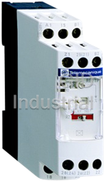
SCHNEIDER ELECTRIC RE7TP13BU
Description
Schneider electric RE7TP13BU timer 300V 5 amp on delay
Part Number
RE7TP13BU
Price
Request Quote
Manufacturer
SCHNEIDER ELECTRIC
Lead Time
Request Quote
Category
Timers
Specifications
Coil Voltage VAC Nom
250V
Contact Configuration
DPCO
Contact Current AC Max
8A
Contact Current DC Max
8A
Contact Voltage AC Max
250V
Contact Voltage DC Max
250V
Current Rating
8A
Delay Time Range
0.05s to 300h
External Depth
80mm
External Length / Height
78mm
External Width
22.5mm
IP / NEMA Rating
IP50
Mounting Type
DIN Rail / Panel
No. of Poles
2
Nom Input Voltage
240V
Operating Temperature Max
50°C
Operating Temperature Min
-20°C
Operating Time Range
0.5 to 300 hrs
Supply Voltage AC Max
240VAC
Supply Voltage AC Min
24VAC
Supply Voltage DC Min
24VDC
Switch Current Max
8A
Switching Current Max
8A
Datasheet

Extracted Text
Electronic timers Selection guide Applications Electronic timers enable simple automation cycles to be set up using wired logic. They can also be used to complement the functions of PLCs. Timers with solid state output reduce the amount of wiring required (wired in series). The durability of these timers is independent of the number of operating cycles. 2 Enclosure type Modular 17.5 mm DIN, width 22.5 mm Timing range Number of ranges 112 Extreme values Depending on model: Depending on model: 0.1…10 s 0.1…3 s 0.1…10 s 3…300 s 1…30 s 0.3…30 s 10…300 s 3…300 s 2…60 min 40 s…60 min Output circuit Control circuit voltage, depending a 24…240 V a 24…240 V on model c 24…240 V c 24…240 V Type RE1 RE9 2/5 2/8 and 2/9 Pages 2/2 Te Relay outputs provide complete isolation between the supply circuit and the output. It is possible to have several output circuits. Universal: multi-voltage, multifunction, Optimum 2 7 or 10 timing ranges 1 single timing range 710 1 0.05…1 s 0.05…1 s Depending on model: 0.15…3 s 0.15…3 s 0.05…0.5 s 0.5…10 s 0.5…10 s 0.05…15 s 1.5…30 s 1.5…30 s 0.1…3 s 5…100 s 5…100 s 0.1…10 s 15…300 s 15…300 s 0.3…30 s 1.5…10 min 1.5 …30 min 3…300 s 15…300 min 20 s…30 min 1.5…30 h 15…300 h or or + a or c 24 V, 42…48 V, 24…240 V a 24 V c 110…240 V c 24 V, 110…130 V, 220…240 V, 380…415 V RE7 RE8 2/8 and 2/9 2/3 Te Zelio Time - timing relays Functions and selection Functions Diagram Operating principle On-delay Control or Timing starts when the relay is energised. When the set time delay (t) has elapsed, the output contact closes. When the supply relay is de-energised, the contact returns to its initial position. The output contact does not close if the duration of the C/O contact 2 control instruction is less than the set time delay. t Timing can also be started by opening of a control contact (models with external control). Off-delay Control or supply Energisation of the relay or closing of the control contact (models with external control) causes the output relay to close instantaneously . Timing starts when the relay is de-energised or when the control contact opens. When the set time delay C/O contact (t) has elapsed, the contact returns to its initial position. If the energisation time or closing time of the control contact is t less than the minimum time specified, the timing period does not start. On and Off-delay Symmetrical Control or supply This function is a combination of the The On and Off delays are equal. On and Off delay functions. The timing C/O contact cycle must be controlled by an external Asymmetrical ta tr contact. The On and Off delays are adjusted by 2 different potentiometers. Timing relay with pulse on energisation Supply Energisation of the relay causes the output contact to close instantaneously and start the timing period. The contact returns to its initial position when the set time delay (t) has elapsed or if the supply is cut off before the end of the timing C/O contact period. t Timing relay with pulse on de-energisation or on opening of a external control contact Control or supply De-energisation of the relay or opening of the external control contact (depending on model) causes the output contact to close instantaneously and start the timing period. When the set time delay (t) has elapsed, the contact returns to its C/O contact initial position. t Flashing relay Symmetrical flashing relay Supply Energisation of the relay starts the The On and Off flashing phases are identical. flashing period and causes the output C/O contact relay to start the flashing cycle. When Asymmetrical flashing relay ta tr the relay is de-energised, the contact The On and Off flashing phases are adjusted by 2 different potentiometers returns to its initial position. (ta and tr). Time delay relays for star-delta starters Supply Energisation of the relay causes the star contactor to close instantaneously and starts the timing period. When the set time delay (t) has elapsed, the star contactor returns to its initial position and the delta contactor closes, after a breaking Star time sufficient for the changeover. Delta t t3 Multifunction relays On-delay - Pulse on energisation contact - Symmetrical flasher Same functions as above + Off-delay - Pulse on energisation contact with externally controlled start - Symmetrical flasher Same functions as above + Star Delta starting (External control of start of the timing period is not possible for the star delta starting function). 2/8 Te Additional functions External control of starting: opening of an external contact connected to the relay starts the timing period. Closing of this contact resets the timer. External control of partial stop of time delay: closing of an external contact connected to the relay allows the timing period to be interrupted. The time elapsed is memorised. Timing restarts as soon as the contact opens. This type of control enables the totalising function to be performed. External adjustment of the time delay: one or more external potentiometers can be used for remote adjustment of the timing period or periods. Output Multifunction relay See pages Solid state RE9-TA 2/12 and 2/13 1 C/O RE7-TL or RE8-TA RE7: 2/20 and 2/21, RE8: 2/38 and 2/39 2 C/O RE7-TP 2/20 and 2/21 2 1 C/O RE7-TM 2/20 and 2/21 Solid state RE9-RA 2/12 and 2/13 1 C/O RE7-RB11 or RE8-RB RE7: 2/24 and 2/25, RE8: 2/38 and 2/39 2 C/O RE7-RL 2/24 and 2/25 2 C/O RE7-RB13 2/24 and 2/25 1 C/O RE8-RA 2/38 and 2/39 1 C/O RE7-RA and RE7-RM 2/24 and 2/25 2 C/O RE7-MA13 2/22 and 2/23 1 C/O RE7-MA11 2/22 and 2/23 1 C/O RE7-MV 2/22 and 2/23 1 C/O RE7-PE or RE8-PE RE7: 2/26 and 2/27, RE8: 2/40 to 2/41 2 C/O RE7-PP 2/26 and 2/27 1 C/O RE8-PT 2/40 and 2/41 2 C/O RE7-PD 2/26 and 2/27 1 C/O RE7-PM 2/26 and 2/27 1 C/O RE8-PD 2/40 and 2/41 1 C/O RE7-CL or RE8-CL RE7: 2/28 and 2/29, RE8: 2/38 and 2/39 2 C/O RE7-CP 2/28 and 2/29 1 C/O RE7-CV 2/28 and 2/29 1 C/O RE8-YG 2/40 and 2/41 2 C/O RE7-YA and RE7-YR 2/30 and 2/31 1 N/C + N/O RE8-YA 2/40 and 2/41 Output Multifunction relay See pages Solid state RE9-MS 2/14 and 2/15 1 C/O RE7-ML 2/32 and 2/33 2 C/O RE7-MY13MW 2/32 and 2/33 2 C/O RE7-MY13BU 2/32 and 2/33 2/9 Te Zelio Time - timing relays Relay output, width 22.5 mm, universal References : pages 2/20 to 2/32 Dimensions : page 2/34 General characteristics Schemes : pages 2/21 to 2/34 Setting-up : pages 2/21 to 2/35 Presentation The RE7 range of relays, with only 23 references, covers all timing applications. These relays offer multi-range timing from 50 ms to 300 h. They are multi-voltage. Three models combine several different functions: multifunction relays. 2 These products have a transparent, hinged flap on their front face to avoid any accidental alteration of the settings. This flap can be directly sealed. Environment Conforming to standards IEC 61812-1, EN 61812-1 Product approvals CSA, GL pending, UL � marking Zelio Time timing relays conform to European regulations relating to � marking Ambient air temperature Storage °C - 40…+ 85 around the device Operation °C - 20…+ 60 Permissible relative humidity range Conforming to IEC 60721-3-3 15…85 % Environmental class 3K3 Vibration resistance Conforming to IEC 6068-2-6, 10 to 55 Hz a = 0.35 ms Shock resistance Conforming to IEC 6068-2-27 15 gn - 11 ms Degree of protection Casing IP 50 Terminals IP 20 Degree of pollution Conforming to IEC 60664-1 3 Overvoltage category Conforming to IEC 60664-1 III Rated insulation voltage Conforming to IEC V 250 Between contact circuit and power supply or between contact circuit Conforming to CSA V 300 and control inputs Test voltage for insulation tests Dielectric test kV 2.5 Shock wave kV 4.8 Voltage limits Power supply circuit 0.85…1.1 Uc Frequency limits Power supply circuit Hz 50/60 ± 5 % Disconnection value Power supply circuit > 0.1 Uc Mounting position In relation to normal Any position without derating vertical mounting plane 2 Connection Maximum c.s.a. Flexible cable without cable end mm 2 x 2.5 2 Flexible cable with cable end mm 2 x 1.5 Tightening torque N.m 0.6…1.1 Immunity to electromagnetic interference (EMC) (Application class 2 conforming to EN 61812-1) Electrostatic discharge Conforming to IEC 61000-4-2 Level 3 (6 kV contact, 8 kV air) Electromagnetic fields Conforming to IEC 61000-4-3 Level 3 (10 V/m) Fast transients Conforming to IEC 61000-4-4 Level 3 (2 kV) Shock waves Conforming to IEC 61000-4-5 Level 3 (2 kV) Radiated and CISPR11 Group 1 class A conducted emissions CISPR22 Class A Consumption c 50/60 Hz a Average consumption 24 V 48 V 110 V 240 V 24 V 48 V 110 V 240 V RE7-ii11BU VA 0.7 1.6 1.8 8.5 W 0.5 1.2 – – RE7-ii12BU and RE7-ii13BU VA 1.2 2 2.8 12.5 W 0.8 1.6 – – RE7-iiiiMW (1) VA 2 2.5 3.2 6 W 2 1 3.2 2 (1) RE7-RBiiMW: current peak on energisation = 1 A / 30 ms. 2/18 Te Zelio Time - timing relays Relay output, width 22.5 mm, universal References : pages 2/20 to 2/32 Dimensions : page 2/34 General characteristics (continued) Schemes : pages 2/21 to 2/34 Setting-up : pages 2/21 to 2/35 Time delay characteristics Setting accuracy As % of the full scale value ± 10 % Repeat accuracy ± 0.2 % Influence of voltage In the voltage range, 0.85…1.1 Un < 0.2 % Influence of temperature < 0.07 %/°C Immunity to micro-breaks ms 3 2 Minimum control pulse ms 20 (except RE7-RB1iMW: 1 s) Reset time ms 50 Output circuit characteristics Maximum switching voltage V z 250 Mechanical durability In millions of operating cycles 20 Current limit Ith A 8 (except RE7-RBiiMW: 5 A) Rated operational limits at 70 °C 24 V 115 V 250 V Conforming to IEC 60947-5-1/1991 AC-15 A333 and VDE 0660 DC-13 A 2 0.2 0.1 Minimum switching capacity 12 V/10 mA Contact material Nickel Silver 90/10 (except RE7-RBiiMU: gold flashed silver alloy) Remote control input characteristics Maximum voltage Applicable to inputs V 60 Y1Z2, X1Z2, X2Z2 Signal delivered by Y1Z2, Switching current mA < 1 X1Z2, X2Z2 control inputs Maximum distance m 50 No galvanic insulation between Compatibility 3/4-wire PNP and NPN Telemecanique sensors or these inputs and the supply other sensors without an internal load Potentiometer for connection Type Linear at ± 20 % between terminals Z1Z2, Z3Z2 Resistance kΩ 47 ± 20 % Power W 0.2 Maximum distance m 25 by shielded cable: shielding linked to terminal Z2 a.c. load d.c. load Curve 1 Curve 2 Load limit curve Electrical durability of contacts on resistive Reduction factor k for inductive loads load in millions of operating cycles (applies to values taken from the durability curve opposite) 1 300 10 0,9 200 0,8 0,7 100 3 1 0,6 2 50 0,5 40 1 0,1 30 0,4 20 A A 0,3 10 0,01 1 0,8 0,6 0,5 0,4 0,3 0,2 0,1 0,2 0,5 1 2 5 10 20 012345678 Current broken in A Power factor on breaking (cos ϕ) Current in A A RE7-RBiiMW A RE7-RBiiMW 1 L/R = 20 ms Example: 2 L/R with load protection diode 3 Resistive load An LC1-F185 contactor supplied with 115 V/50 Hz for a consumption of 55 VA or a current + consumption equal to 0.1 A and cos ϕ = 0.3 RE7 For 0.1 A, curve 1 indicates a durability of approximately 1.5 million operating cycles. As the load is inductive, it is necessary to apply a reduction coefficient k to this number of cycles, as indicated by curve 2. K For cos ϕ = 0.3: k = 0.6 – The electrical durability therefore becomes: 6 1.5 10 operating cycles x 0.6 = 900 000 operating cycles 2/19 Te Millions of operating cycles Reduction factor k Voltage in V Zelio Time - timing relays Relay output, width 22.5 mm, universal On-delay relays Available 2nd Quarter 2001 Functions, references On-delay relays Time delay adjustable from 0.05 s to 300 h in 10 ranges (see setting-up procedure on page opposite). On-delay relay External control for External control for partial Start on start of time delay stop of time delay energisation RE7-TM (for totalising function) RE7-TL, TM, TP RE7-TM de-energised Supply Supply Supply energised open 15/18 (25/28) (Y1Z2) (X1Z2) Start Partial stop 2 C/O 15/16 (25/26) closed t1 t3 t2 t: adjustable On-delay t 15/18 C/O 15/16 C/O 15/18 t 15/16 tt = t1 + t2 + t3 Conversion of second changeover contact to instantaneous mode by means of switch R2 RE7-TP13BU R2 R2 Delay Inst Delay Inst Supply Supply C/O 25/28 21/24 C/O 25/26 21/22 t Functions (see Supply Relay Reference Weight diagrams above) voltages output kg On-delay relay a or c 24 V 1 C/O RE7-TL11BU 0.150 c 110…240 V On-delay relay a or c 24 V 1 C/O RE7-TM11BU 0.150 External control possible for: a or c 42…48 V - start of time delay c 110…240 V RE7- T - partial stop of time delay - adjustment of time delay (1) On-delay relay a or c 24 V 2 C/O (2) RE7-TP13BU 0.150 Remote control possible for: a or c 42…48 V - adjustment of time delay (1) c 110…240 V (1) By external potentiometer, to be ordered separately. If external potentiometer is fitted, the internal potentiometer is automatically disconnected. (2) A switch on the front face of the relay allows the second changeover contact to be used in instantaneous mode. 2/20 Te Zelio Time - timing relays Relay output, width 22.5 mm, universal On-delay relays Schemes, setting-up Schemes Terminal blocks RE7-TL11BU RE7-TP13BU RE7-TM11BU A1 15 B1 A1 15 B1 A1 15 B1 Z1 25 (21) B2 Z1 B2 2 28 (24) 26 (22) Z2 X1 Y1 Z2 18 16 A2 18 16 A2 18 16 A2 Recommended application schemes Start on energisation Start by external contact External control of partial stop B1 B2 A1 B1 B2 A1 Y1 B1 B2 A1 X1 Z2 Z2 A2 A2 A2 Potentiometer wiring Wiring precautions Z1 Z2 X1 or Y1 or Z1 A2 Z2 A2 No galvanic insulation between supply terminals A1, A2, B1, B2 and control inputs X1, Y1, Z1, Z2. Setting-up 1 Potentiometer for fine adjustment of the time delay, graduated in % of range max. setting 2. 2 10-position timing range selector: 1 0.05…1 s 0.5…10 s 5…100 s 1.5…30 min 1.5…30 h 4 0.15…3 s 1.5…30 s 15…300 s 15…300 min 15…300 h 2 3 Switch for converting the second C/O contact to instantaneous mode (for RE7-TP13BU). 3 4 LEDs, depending on the model: - Green LED U/T: flashes during the time delay period, permanently on outside the time delay period. st - Yellow LED R1: on when the 1 relay is energised. nd - Yellow LED R2: on when the 2 relay is energised. Adjustment of the time delay 1 40 - Select the timing range immediately greater than the time required, using selector switch 2. Example: time required 12 s; range selected 30 s. 2 30 s x. % - Using potentiometer 1 display the required time value as a % of value 2. t x 100 12 x 100 1 = –––––– i.e. ––––––– = 40 2 30 2/21 Te c 110 … 240 V B1 z 42 … 48 V A2 z 24 V A1 16 18 15 c 110 … 240 V Supply B1 z 42…48 V A2 B2 A1 z 24 V 16 18 15 26 (22) 28 25 (24) (21) c 110 … 240 V B1 z 42…48 V A2 B2 z 24 V A1 16 18 15 Zelio Time - timing relays Characteristics : Relay output, width 22.5 mm, universal pages 2/18 and 2/19 On-delay and Off-delay relays Available 2nd Dimensions : page 2/34 Quarter 2001 Schemes : Functions, references page 2/34 Setting-up : page 2/35 On-delay and Off-delay relays , Time delay adjustable from 0.05 s to 300 h in 10 ranges (see setting-up procedure on page opposite). External control for Remote control for partial stop of time delay start of time delay RE7-MA11BU and MV11BU RE7-MA and MV Y1Z2 de-energised Supply Start energised Y1Z2 open Start C/O 15/18 15/16 2 closed C/O 15/18 (25/28) ta : adjustable On-delay Partial stop 15/16 (25/26) X1Z2 tr: adjustable Off-delay of time delay ta tr ta = t1 + t2 t1 ts t2 t3 ts t4 tr = t3 + t4 ts: partial stop time Conversion of second changeover contact to instantaneous mode by means of switch R2 RE7-MA13BU R2 R2 Delay Inst Delay Inst Supply Supply 21/24 Start C/O 21/22 C/O 25/28 25/26 ta tr Functions Supply Relay Reference Weight (see diagrams above) voltages output kg Symmetrical relays: On and Off delay times are equal. On-delay and Off-delay relay a or c 24 V 1 C/O RE7-MA11BU 0.150 External control possible for a or c 42…48 V - partial stop of time delay c 110…240 V - adjustment of time delay (1) Start control via external contact only On-delay and Off-delay relay a or c 24 V 2 C/O (2) RE7-MA13BU 0.150 RE7-M Start control via a or c 42…48 V external contact only c 110…240 V Asymmetrical relays: On and Off delay times are adjusted separately. On-delay and Off-delay relay a or c 24 V 1 C/O RE7-MV11BU 0.150 External control possible for a or c 42…48 V - partial stop of time delay c 110…240 V - adjustment of time delays (1) Start control via external contact only (1) By external potentiometer(s), to be ordered separately. If external potentiometer(s) is/are fitted, the internal potentiometer(s) is/are automatically disconnected. (2) A switch on the front face of the relay allows the second changeover contact to be used in instantaneous mode. 2/22 Te Zelio Time - timing relays Relay output, width 22.5 mm, universal On-delay and Off-delay relays Characteristics : pages 2/18 and 2/19 References : Schemes, setting-up page 2/22 Dimensions : page 2/34 Schemes Terminal blocks RE7-MA13BU RE7-MA11BU RE7-MV11BU A1 15 B1 A1 15 B1 A1 15 B1 Z1 B2 Z1 Z3 B2 Y1 25 (21) B2 X1 Y1 Z2 X1 Y1 Z2 2 28 (24) 26 (22) Z2 18 16 A2 18 16 A2 18 16 A2 Recommended application schemes (for other schemes, see page 2/34) Start by external control External control of partial stop B1 B2 A1 Y1 B1 B2 A1 X1 Z2 Z2 A2 A2 Potentiometer wiring Potentiometer wiring Wiring precautions for symmetrical relay for asymmetrical relays RE7-MA RE7-MV11BU Z3 Z1 Z1 X1 or Y1 or Z1 Z2 A2 Z2 A2 Z2 (1) (2) A2 No galvanic insulation between supply terminals A1, A2, B1, B2 and control inputs X1, Y1, Z1, Z2. (1) On-delay adjustment (2) Off-delay adjustment Setting-up procedure Symmetrical Asymmetrical timing relay timing relay 1 Potentiometer for fine adjustment of the time delay, graduated in % of range max. setting 2 2 10-position timing range selector : 4 1 0.05…1 s 0.5…10 s 5…100 s 1.5…30 min 1.5…30 h 1 4 A ] 0.15…3 s 1.5…30 s 15…300 s 15…300 min 15…300 h 2 2 1 B ] A On-delay adjustment (ta). 2 3 B Off-delay adjustment (tr). 3 Switch for converting the second changeover contct to instantaneous mode (RE7-MA13BU). 4 LEDs, depending on the model : - Green LED: flashes during the time delay period, permanently on outside the time delay period st - Yellow LED 1: on when the 1 relay is energised nd - Yellow LED 2: on when the 2 relay is energised Adjustment of the time delay 1 40 - Select the timing range value immediately greater than the time required using selector switch 2. Example: required time 12 s; range selected 30 s. 2 30 s x. % - Using potentiometer 1 display the required time as a % of value 2. t x 100 12 x 100 1 = –––––– i.e. ––––––– = 40 2 30 2/23 Te c 110 … 240 V B1 A2 B2 z 42…48 V A1 z 24 V 16 18 15 26 (22) 28 25 (24) (21) c 110 … 240 V B1 z 42…48 V A2 B2 z 24 V A1 16 18 15 Supply B1 A2 B2 A1 16 18 15 Zelio Time - timing relays Relay output, width 22.5 mm, universal Off-delay relays Available 2nd Quarter 2001 Functions, references Off-delay relays Off-delay relays External control for Remote control for RE7-RB start of time delay partial stop of time delay RE7-RA, RM RE7-RA, RM > 1 s (1) > 20 ms Supply Supply Start Y1Z2 de-energised energised C/O 15/18 (25/28) Start Partial stop X1Z2 open 15/16 (25/26) closed 2 t C/O 15/18 C/O t: adjustable Off-delay 15/18 15/16 15/16 t = t1 + t2 t t1 ts t2 t : partial stop time Conversion of second changeover contact to instantaneous mode by means of switch R2 RE7-RL13BU R2 R2 Delay Inst Delay Inst Supply Supply Start C/O 21/24 21/22 C/O 25/28 25/26 tr Functions Supply Relay Reference Weight (see diagrams above) voltages output kg On de-energisation, adjustable from 0.05 s to 10 min in 7 ranges (see setting-up procedure on page opposite). Off-delay relay a or c 24…240 V 1 C/O RE7-RB11MW (1) 0.150 Off-delay relay a or c 24…240 V 2 C/O RE7-RB13MW (1) 0.150 Remote control possible for: - adjustment of time delay (2) RE7-R On opening of external control contact, adjustable from 0.05 s to 300 h in 10 ranges (see setting-up procedure on page opposite). Off-delay relay a or c 24 V 1 C/O RE7-RA11BU 0.150 External control possible for: a or c 42…48 V - partial stop of time delay c 110…240 V - adjustment of time delay (2) On opening of low level external control contact, adjustable from 0.05 s to 300 h in 10 ranges (see setting-up procedure on page opposite). Off-delay relay a or c 24 V 1 C/O RE7-RM11BU 0.150 External control possible for: a or c 42…48 V - partial stop of time delay c 110…240 V - adjustment of time delay (2) Off-delay relay a or c 24 V 2 C/O (3) RE7-RL13BU 0.150 a or c 42…48 V c 110…240 V (1) If the device has been stored, de-energised, for more than a month, it must be energised for about 15 seconds to activate it. Subsequently, a time of > 1 s is enough to activate the time delay. If this time is not complied with, the relay will remain energised indefinitely. (2) By external potentiometer, to be ordered separately. If external potentiometer is fitted, the internal potentiometer is automatically disconnected. (3) A switch on the front face of the relay allows the second changeover contact to be used in instantaneous mode. 2/24 Te Zelio Time - timing relays Relay output, width 22.5 mm, universal Off-delay relays Schemes, setting-up Schemes Terminal blocks RE7-RL13BU RE7-RB11MW RE7-RB13MW RE7-RM11BU and RE7-RA11BU A1 15 B1 A1 15 B1 A1 15 A1 15 Z1 B2 Y1 25 (21) B2 Z1 25 X1 Y1 Z2 28 (24) 26 (22) Z2 28 26 Z2 2 18 16 A2 18 16 A2 18 16 A2 18 16 A2 Recommended application schemes Start on de-energisation Start by low level Remote control Potentiometer wiring external control of partial stop RE7-RB RE7-RM and RL RE7-RA and RM Z1 B1 B2 A1 B1 B2 A1 A1 Y1 X1 Z2 A2 Z2 A2 Z2 A2 A2 Start by external control Wiring precautions RE7-RA RE7-RM and RL + + A1 B2 B1 Y1 Y1 Y1 A2 Z2 A2 A2 A2 – – No galvanic insulation between supply terminals A1, A2, B1, B2 and control inputs X1, Y1, Z1, Z2. Setting-up procedure 1 Potentiometer for fine adjustment of the time delay, graduated in % of range max. setting 2. 2 Timing range selector: 1 - 10-position (RE7-RA, RM, RL) 0.05…1 s 0.5…10 s 5…100 s 1.5…30 min 1.5…30 h 4 0.15…3.s 1.5…30 s 15…300 s 15…300 min 15…300 h 2 - 7-position (RE7-RB) 0.05…1 s 0.5…10 s 5…100 s 1.5…10 min 0.15…3.s 1.5…30 s 15…300 s 3 3 Switch for converting the second changeover contact to instantaneous mode (RE7-RL13BU). 4 LEDs, depending on the model: - Green LED U/T: flashes during the time delay period, permanently on outside the time delay period. st - Yellow LED R1: on when 1 relay is energised. nd - Yellow LED R2: on when 2 relay is energised. - RE7-RBiiMW: the green LED does not flash during the time delay period and there is only one yellow LED (R). 1 40 Adjustment of the time delay - Select the timing range immediately greater than the time required, using selector switch 2. 2 30 s x. % Example: required time 12 s; range selected 30 s. - Using potentiometer 1 display the required time value as a % of value 2. t x 100 12 x 100 1 = –––––– i.e. ––––––– = 40 2 30 2/25 Te c 110 … 240 V z 24 … 240 V B1 A2 B2 A1 16 18 15 26 (22) 28 25 (24) (21) a 42…48 V c 110 … 240 V z 42…48 V c 42…48 V A2 A1 z 24 V 16 18 15 a 24 V c 110 … 240 V A2 A1 c 24 V z 42…48 V z 24 V 16 18 15 26 28 25 Supply B1 A2 B2 A1 16 18 15 Zelio Time - timing relays Characteristics : Relay output, width 22.5 mm, universal pages 2/18 and 2/19 Pulse on energisation relays Available 2nd Dimensions : page 2/34 Quarter 2001 Schemes : Functions, references page 2/34 Setting-up : page 2/35 Pulse on energisation relays Time delay adjustable from 0.05 s to 300 h in 10 ranges (see setting-up procedure on page opposite) Pulse on energisation relay Start on opening of External control for Start on energisation external control contact partial stop of time delay RE7-PE, PP RE7-PM, PD (for totalising function) RE7-PM Supply Supply Supply de-energised 2 energised 15/18 (25/28) open C/O Start Y1Z2 Partial stop X1Z2 15/16 (25/26) closed t1 t2 t3 t C/O 15/18 C/O t: pulse time 15/16 ts: partial stop time t 15/18 15/16 t = t1 + t2 + t3 t Conversion of second changeover contact to instantaneous mode by means of switch R2 RE7-PP R2 R2 Delay Inst Delay Inst Supply Supply C/O 25/28 C/O 21/24 25/26 21/22 t RE7-PD R2 R2 Delay Inst Delay Inst Supply Supply Start Y1Z2 C/O 21/24 21/22 C/O 25/28 25/26 t Functions Supply Relay Reference Weight (see diagrams above) voltages output kg 1 Start on energisation Pulse on energisation relay a or c 24 V 1 C/O RE7-PE11BU 0.150 c 110…240 V Pulse on energisation relay a or c 24 V 2 C/O (1) RE7-PP13BU 0.150 External control possible for a or c 42…48 V - adjustment of time delay (2) c 110 …240 V RE7-P 1 Start on opening of external control contact Pulse on energisation relay a or c 24 V 1 C/O RE7-PM11BU 0.150 External control possible for a or c 42…48 V - partial stop of time delay c 110…240 V - adjustment of time delay (2) Pulse on energisation relays a or c 24 V 2 C/O (1) RE7-PD13BU 0.150 a or c 42…48 V c 110…240 V (1) A switch on the front face of the relay allows the second changeover contact to be used in instantaneous mode. (2) By external potentiometer, to be ordered separately. If external potentiometer is fitted, the internal potentiometer is automatically disconnected. 2/26 Te Zelio Time - timing relays Relay output, width 22.5 mm, universal Pulse on energisation relays Characteristics : pages 2/18 and 2/19 References : Schemes, setting-up page 2/26 Dimensions : page 2/34 Schemes Terminal blocks RE7-PE11BU RE7-PP13BU RE7-PD13BU RE7-PM11BU A1 15 B1 A1 15 B1 A1 15 B1 A1 15 B1 Z1 B2 Z1 25 (21) B2 Y1 25 (21) B2 2 X1 Y1 Z2 28 (24) 26 (22) Z2 28 (24) 26 (22) Z2 18 16 A2 18 16 A2 18 16 A2 18 16 A2 Recommended application schemes (for other schemes, see page 2/34) Start on energisation Start by external contact External control of partial stop Potentiometer wiring RE7-PE, PP RE7-PM, PD Z1 B1 B2 A1 B1 B2 A1 Y1 X1 Z2 B1 B2 A1 A2 Z2 Z2 A2 A2 A2 Wiring precautions X1 or Y1 or Z1 Z2 A2 No galvanic insulation between supply terminals A1, A2, B1, B2 and control inputs X1, Y1, Z1, Z2. (1) a or c 42…48 V: RE7-PP. Setting-up procedure 1 Potentiometer for fine adjustment of the time delay, graduated in % of range max. setting 2. 2 10-position timing range selector : 1 0.05…1 s 0.5…10 s 5…100 s 1.5…30 min 1.5…30 h 4 0.15…3 s 1.5…30 s 15…300 s 15…300 min 15…300 h 2 3 Switch for converting the second changeover contact to instantaneous mode (RE7-PP13BU and PD13BU). 3 4 LEDs, depending on the model: - Green LED: flashes during the time delay period (except for the first 2 timing ranges), permanently on outside the time delay period st - Yellow LED 1: on when 1 relay is energised nd - Yellow LED 2: on when 2 relay is energised Adjustment of the time delay 1 40 - Select the timing range immediately greater than the time required using selector switch 2. Example: required time 12 s; range selected 30 s. 2 30 s x. % - Using potentiometer 1 display the required time as a % of value 2. t x 100 12 x 100 1 = –––––– i.e. ––––––– = 40 2 30 2/27 Te Supply c 110 … 240 V B1 (1) A2 z 24 V A1 16 18 15 c 110 … 240 V B1 z 42…48 V A2 B2 A1 z 24 V 16 18 15 26 (22) 28 25 (24) (21) c 110 … 240 V B1 z 42…48 V A2 B2 A1 z 24 V 16 18 15 26 (22) 28 25 (24) (21) B1 B2 A2 A1 16 18 15 Zelio Time - timing relays Characteristics : Relay output, width 22.5 mm, universal pages 2/18 and 2/19 Flashing relays Available 2nd Dimensions : page 2/34 Quarter 2001 Schemes : Functions, references page 2/34 Setting-up : page 2/35 Flashing relays Time delay adjustable from 0.05 s to 300 h in 10 ranges (see setting-up procedure on page opposite). Symmetrical flashing relay Asymmetrical flashing relay RE7-CL, CP Start during the ON period Start during the OFF period RE7-CV (X2Z2 linked) RE7-CV (X2Z2 not linked) de-energised Supply Supply Supply energised 2 C/O 15/18 (25/28) 15/18 (25/28) open C/O C/O 15/16 (25/26) 15/16 (25/26) closed t t ta tr tr ta t, t1 and t2 : adjustable time delays ts: partial stop time t : flashing time ta: On-delay period External control for Conversion of second changeover contact tr: Off-delay period partial stop of time delay to instantaneous mode by means of switch R2 ta = t1 + t2 RE7-CV RE7-CP tr = t3 + t4 R2 R2 Delay Inst Delay Inst Supply Supply Supply C/O 15/18 (25/28) 25/28 21/24 C/O C/O 15/16 (25/26) 25/26 21/22 t t Partial stop X1Z2 t1 tst2t3 ts t4 Functions Supply Relay Reference Weight (see diagrams above) voltages output kg Symmetrical relays with start during OFF period Flashing relay a or c 24 V 1 C/O RE7-CL11BU 0.150 c 110 … 240 V Flashing relay a or c 24 V 2 C/O (1) RE7-CP13BU 0.150 External control possible for a or c 42…48 V - adjustment of time delay (2) c 110…240 V RE7-C Asymmetrical relay with separate adjustment of On-delay and Off-delay Flashing relay a or c 24 V 1 C/O RE7-CV11BU 0.150 External control possible for a or c 42…48 V - start period c 110…240 V - adjustment of time delays (2) - partial stop (1) A switch on the front face of the relay allows the second changeover contact to be used in instantaneous mode. (2) By external potentiometers, to be ordered separately. If external potentiometers are fitted, the internal potentiometers are automatically disconnected. 2/28 Te Zelio Time - timing relays Relay output, width 22.5 mm, universal Flashing relays Characteristics : pages 2/18 and 2/19 References : Schemes, setting-up page 2/28 Dimensions : page 2/34 Schemes Terminal blocks RE7-CL11BU RE7-CP13BU RE7-CV11BU A1 15 B1 A1 15 B1 A1 15 B1 Z1 25 (21) B2 Z1 Z3 B2 2 28 (24) 26 (22) Z2 X1 X2 Z2 18 16 A2 18 16 A2 18 16 A2 Recommended application schemes (for other schemes: see page 2/34) Start on energisation Start period selection External control of partial stop RE7-CV RE7-CV B1 B2 A1 B1 B2 A1 X2 B1 B2 A1 X1 (2) Z2 Z2 A2 A2 A2 Potentiometer wiring Potentiometer wiring Wiring precautions RE7-CV RE7-CP Z3 Z1 X1 or Y1 or Z1 Z1 Z2 A2 Z2 A2 A2 Z2 (3) (4) No galvanic insulation between supply terminals A1, A2, B1, B2 and control inputs X1, Y1, Z1, Z2. (1) a or c 42…48 V: RE7-CP13BU and RE7-CV11BU. (2) Start during ON period: X2Z2 connected. Start during OFF period: X2-Z2 not linked. (3) Off-delay adjustment (tr) (contact 15/16 closed). (4) On-delay adjustment (ta) (contact 15/18 closed). Setting-up procedure Symmetrical Asymmetrical flashing relay flashing relay 1 Potentiometer for fine adjustment of the time delay in % of range max. setting 2. 2 10-position timing range selector : 4 1 0.05…1 s 0.5…10 s 5…100 s 15…300 min 1.5…30 h 1 4 A ] 0.15…3 s 1.5…30 s 15…300 s 1.5…30 min 15…300 h 2 2 1 B A Adjustable On-delay (ta). ] 2 3 B Adjustable Off-delay (tr). 3 Switch for converting the second changeover contact to instantaneous mode (RE7-CP13BU). 4 LEDs, depending on the model : - Green LED: flashes during the time delay period, permanently on outside the time delay period st - Yellow LED 1: on when 1 relay is energised nd - Yellow LED 2: on when 2 relay is energised Adjustment of the time delay 1 40 - Select the timing range immediately greater than the time required using selector switch 2. Example: required time 12 s; range selected 30 s. 2 30 s x. % - Using potentiometer 1 display the required time as a % of value 2. t x 100 12 x 100 1 = –––––– i.e. ––––––– = 40 2 30 2/29 Te c 110 … 240 V B1 (1) A2 z 24 V A1 16 18 15 c 110 … 240 V B1 z 42 … 48 V A2 B2 A1 z 24 V 16 18 15 26 (22) 28 25 (24) (21) Supply c 110 … 240 V B1 z 42…48 V A2 B2 z 24 V A1 16 18 15 Zelio Time - timing relays Characteristics : Relay output, width 22.5 mm, universal pages 2/18 and 2/19 Timing relays for star-delta starting Available 2nd Dimensions : page 2/34 Quarter 2001 Schemes : Functions, references page 2/34 Setting-up : page 2/35 Timing relays for star-delta starters (1) Time delay adjustable from 0.05 s to 300 h in 10 ranges (see setting-up procedure on page opposite). Timing relays for star-delta starters With double On-delay With contact for switching to star connection RE7-YA RE7-YR de-energised Supply Supply energised 2 C/O1 15/18 C/O1 17/18 15/16 open C/O2 17/28 closed C/O2 25/28 25/26 star t: adjustable time delay (star) K1 star K1 delta K3 delta K3 t 50 ms t 50 ms Functions Supply Output Reference Weight (see diagrams below) voltages relay kg With double On-delay a or c 24 V 2 C/O RE7-YA12BU 0.150 a or c 42…48 V c 110…240 V RE7-Y With contact for switching a or c 24 V 2 C/O RE7-YR12BU 0.150 to star connection a or c 42…48 V with common 1 c 110…240 V point (1) Adjustable time delay for operation in star connection and and fixed (50 ms) for switching from star to delta connection to ensure sufficient breaking time. 2/30 Te Zelio Time - timing relays Relay output, width 22.5 mm, universal Timing relays for star-delta starting Characteristics : pages 2/18 and 2/19 References : Schemes, setting-up page 2/30 Dimensions : page 2/34 Schemes (Star-delta starter application) Power scheme Control schemes RE7-YA12BU Star-delta function with double On-delay timing Terminal block RE7-YA F3 A1 15 B1 25 B2 F2 S1 2 K1 28 26 Z2 K2 K3 18 16 A2 S2 K2 K1 14 13 K1T K1T F2 W1 V2 K3 K1 V1 M1 U2 3 K1 K1T K2 K3 W2 U1 K1T = RE7-YA relay YN Δ Power scheme Control schemes 1 RE7-YR12BU Star-delta function with contact for switching to star connection Terminal block RE7-YR F3 A1 17 B1 17 B2 F2 S1 K1 28 26 Z2 K2 K3 K2 18 16 A2 S2 K1T K2 K1 F2 W1 V2 K3 K1 U2 V1 M1 3 W2 K1T K1 K3 K2 U1 K1T = Relay RE7-YR YN Δ No galvanic insulation between supply terminals A1, A2, B1, B2 and supply terminal Z2. This terminal must therefore never be used (factory setting). Setting-up procedure 1 Potentiometer for fine adjustment of the time delay, graduated in % of range max. setting 2. 2 10-position timing range selector : 1 0.05…1 s 0.5…10 s 5…100 s 1.5…30 min 1.5…30 h 3 0.15…3 s 1.5…30 s 15…300 s 15…300 min 15…300 h 2 3 LEDs, depending on model : - Green LED: flashes during the time delay period (except the first 2 timing ranges), permanently on outside the time delay period st - Yellow LED 1: on when 1 relay is energised nd - Yellow LED 2: on when 2 relay is energised Adjustment of the time delay 1 40 - Select the timing range immediately greater than the time required using selector switch 2. Example: required time 12 s; range selected 30 s. 2 30 s x. % - Using potentiometer 1 display the required time as a % of value 2. t x 100 12 x 100 1 = –––––– i.e. ––––––– = 40 2 30 2/31 Te 2 1 2 1 L1 2 1 2 1 L1 L2 4 3 4 3 L2 4 3 4 3 L3 6 5 6 5 L3 6 5 6 5 2 1 2 1 4 3 4 3 6 5 6 5 2 1 2 1 4 3 4 3 6 5 6 5 A2 A1 A2 A1 21 22 15 16 14 13 22 21 96 95 14 13 22 21 96 95 A2 A1 A2 A1 21 22 18 17 54 53 A2 A1 21 22 28 17 A2 A1 A2 A1 21 22 25 28 13 14 A2 A1 14 13 14 13 B1 B1 A2 B2 A2 B2 A1 A1 16 16 18 18 15 17 26 26 28 28 25 Zelio Time - timing relays Relay output, width 22.5 mm, universal Multifunction relays Available 2nd Quarter 2001 Functions, references Multifunction relays Adjustable time delay from 0.05 s to 300 h in 10 ranges (see setting-up procedure on page opposite). On-delay relay Pulse on energisation relay Flashing relay with RE7-ML, MY with start on energisation start during the ON period 1 RE7-ML, MY RE7-ML, MY de-energised Supply Supply Supply energised open 2 C/O 15/18 (25/28) C/O 15/18 (25/28) C/O 15/18 (25/28) closed 15/16 (25/26) 15/16 (25/26) 15/16 (25/26) t: adjustable time delay t t t t t = t1 + t2 + t3 ts: partial stop time Flashing relay with Off-delay relay Pulse on energisation relay with start during the OFF period RE7-ML, MY start on opening of the 1 RE7-ML, MY external control contact RE7-ML, MY Supply Supply Supply Y1Z2 Y1Z2 Start Start C/O 15/18 (25/28) 15/18 (25/28) C/O 15/16 (25/26) C/O 15/18 (25/28) 15/16 (25/26) 15/16 (25/26) t t t t Relay for star-delta starters with: External control for External control for double On-delay timing contact for switching to star start of time delay partial stop of time delay 1 RE7-MY connection RE7-MY (example on On-delay function) (1) (example on pulse on energisation RE7-ML, MY relay) (1) RE7-ML, MY Supply Supply Supply Supply C/O1 C/O1 15/18 17/18 Partial stop X1Z2 15/16 (Y1Z2) Start C/O2 17/28 25/28 C/O 25/26 star 15/18 C/O 15/18 15/16 15/16 delta star t t1 ts t2 ts t3 t 50 ms delta t t 50 ms 1 1 6 function relay , , , , Functions (see diagrams Supply Relay Reference Weight above) voltages output kg On-delay relay a or c 24 V 1 C/O RE7-ML11BU 0.150 Off-delay relay a or c 42…48 V Pulse on energisation relay c 110…240 V - start on energisation - start on opening of remote control contact Flashing relay with start during the OFF period Flashing relay with start during the ON period External control possible for: - start of time delay - partial stop of time delay - adjustment of time delay (2) RE7-MY 1 1 1 8 function relay , , , , , , As for 6 function relay (3) + a or c 24 V 2 C/O (4) RE7-MY13BU 0.150 Relay for star-delta c 110 …240 V starting - with double On-delay timing - with contact for switching to star connection a or c 24…240 V 2 C/O (4) RE7-MY13MW 0.150 (1) For use on other functions, please see the diagrams relating to the single function products. (2) By external potentiometer, to be ordered separately. If external potentiometer is fitted, the internal potentiometer is automatically disconnected. (3) Except control of partial stop of time delay for RE7-MY13BU. (4) A switch on the front face of the relay allows the second changeover contact to be used in instantaneous mode. 2/32 Te Zelio Time - timing relays Relay output, width 22.5 mm, universal Multifunction relays Schemes, setting-up Schemes Terminal blocks RE7-ML11BU RE7-MY13BU RE7-MY13MW A1 15 B1 A1 15 B1 A1 15 Y1 Z1 B2 Z1 25 (21) Y1 Z1 25 (21) X1 2 X1 Y1 Z2 28 (24) 26 (22) Z2 28 (24) 26 (22) Z2 18 16 A2 18 16 A2 18 16 A2 Recommended application schemes Start on energisation Start by external control External control of partial stop B1 B2 A1 Y1 B1 B2 A1 B1 B2 A1 X1 Z2 A2 A2 Z2 A2 Potentiometer wiring Wiring precautions Z1 X1 or Y1 or Z1 Z2 A2 Z2 A2 No galvanic insulation between supply terminals A1, A2, B1, B2 and control inputs X1, Y1, Z1, Z2. (1) c 110…240 V: RE7-ML11BU or RE7-MY13BU, a or c 24…240 V: RE7-MY13MW. (2) c or a 42…48 V: RE7-ML11BU. (3) c or a 24 V: RE7-ML11BU or RE7-MY13BU. Setting-up procedure 1 Potentiometer for fine adjustment of the time delay, graduated in % of range max. setting 2. 2 10-position timing range selector: 0.05…1 s 5…100 s 15…300 min 1 0.15…3 s 15…300 s 1.5…30 h 5 0.5…10 s 1.5…30 min 15…300 h 2 1.5…30 s 4 3 10-position function selector switch (positions which are not used have no marking; the output relay(s) 3 stay(s) in the Off position, whatever the control instructions are). 4 Switch for converting the second changeover contact to instantaneous mode (depending on model). 5 LEDs, depending on the model: - Green LED: flashes during the time delay period (except for the first 2 timing ranges), permanently on outside the time delay period. st - Yellow LED 1: on when 1 relay is energised. nd - Yellow LED 2: on when 2 relay is energised. Adjustment of the time delay 1 40 - Select the timing range immediately greater than the time required, using selector switch 2. Example: required time 12 s; range selected 30 s. x. % 2 30 s - Using potentiometer 1 display the required timing value as a % of value 2. t x 100 12 x 100 1 = –––––– i.e. ––––––– = 40 2 30 2/33 Te (1) B1 A2 (2) A1 (3) 16 18 15 Supply (1) B1 (2) A2 A1 (3) 16 18 15 26 (22) 28 25 (24) (21) (1) (2) A2 A1 (3) 16 18 15 26 (22) 28 25 (24) (21) Zelio Time - timing relays Relay output, width 22.5 mm, universal Characteristics : pages 2/18 and 2/19 References : Dimensions, mounting pages 2/20 to 2/32 Setting-up : page 2/35 RE7 Dimensions Rail mounting 2 80 22,5 89,5 82 Screw fixing Ş4 2/34 Te 6 78 6 78 Zelio Time - timing relays Relay output, width 22.5 mm, universal Characteristics : pages 2/18 and 2/19 References : Schemes pages 2/20 to 2/32 Dimensions : page 2/34 Schemes : pages 2/21 to 2/34 Schemes Control of several relays with a single external control contact Connection of Telemecanique 3-wire NPN or PNP sensor + 24 A1, B1 or B2 A1, B1 or B2 A1, B1 or B2 A1, B1 or B2 BN NPN Y1 or X1 Y1 or X1 Y1 or X1 or Y1 BK PNP Z2 Z2 Z2 48 V A2 A2 A2 A2 Z2 BU 2 – It is advisable to follow the recommended wiring schemes detailed above and on previous pages. However, the connections below are possible if the restrictions given are taken into account. Connection of an external control contact without using terminal Z2: - possible on all RE7 relays with external control option except RE7-RA11BU - d.c. supply only + + A1, B1 or B2 A1, B1 or B2 Y1 or X1 Y1 or X1 Z2 Z2 A2 A2 – – Connection of a Telemecanique 3-wire NPN or PNP sensor without using terminal Z2: - only possible on relay RE7-iiiiBU - d.c. supply only + + BN BN B1B2 B1B2 24 24 Y1 Y1 BK BK NPN PNP or or A2 Z2 BU A2 Z2 BU 48 V 48 V – – 2/35 Te Supply
Frequently asked questions
How does Industrial Trading differ from its competitors?

Is there a warranty for the RE7TP13BU?
Which carrier will Industrial Trading use to ship my parts?
Can I buy parts from Industrial Trading if I am outside the USA?
Which payment methods does Industrial Trading accept?
Why buy from GID?

Quality
We are industry veterans who take pride in our work

Protection
Avoid the dangers of risky trading in the gray market

Access
Our network of suppliers is ready and at your disposal

Savings
Maintain legacy systems to prevent costly downtime

Speed
Time is of the essence, and we are respectful of yours
Related Products
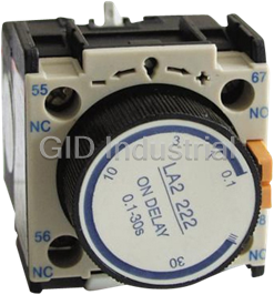
Schneider Electric LA2D20 0.1~3S On Delay Timer

Schneider Electric LA2-DT2 Timer Block; .01-30 Seconds Time Delay On
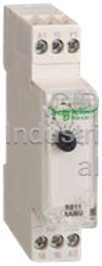
Schneider Electric RE11RAMU 24VAC/Dc-240VAC, 1CO On-Delay Timer
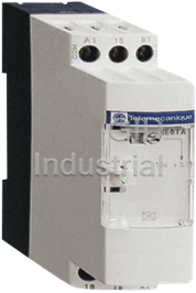
Schneider electric RE8TA21BU industrial timing relay 3..300s - type A - 24 V AC/DC, 110..240 V AC- 1...
Request a Quote

The quote request has been received
Close

Facing challenges or have inquiries? Feel free to contact us!
Call Us +1-469-283-2440
What they say about us
FANTASTIC RESOURCE
One of our top priorities is maintaining our business with precision, and we are constantly looking for affiliates that can help us achieve our goal. With the aid of GID Industrial, our obsolete product management has never been more efficient. They have been a great resource to our company, and have quickly become a go-to supplier on our list!
Bucher Emhart Glass
EXCELLENT SERVICE
With our strict fundamentals and high expectations, we were surprised when we came across GID Industrial and their competitive pricing. When we approached them with our issue, they were incredibly confident in being able to provide us with a seamless solution at the best price for us. GID Industrial quickly understood our needs and provided us with excellent service, as well as fully tested product to ensure what we received would be the right fit for our company.
Fuji
HARD TO FIND A BETTER PROVIDER
Our company provides services to aid in the manufacture of technological products, such as semiconductors and flat panel displays, and often searching for distributors of obsolete product we require can waste time and money. Finding GID Industrial proved to be a great asset to our company, with cost effective solutions and superior knowledge on all of their materials, it’d be hard to find a better provider of obsolete or hard to find products.
Applied Materials
CONSISTENTLY DELIVERS QUALITY SOLUTIONS
Over the years, the equipment used in our company becomes discontinued, but they’re still of great use to us and our customers. Once these products are no longer available through the manufacturer, finding a reliable, quick supplier is a necessity, and luckily for us, GID Industrial has provided the most trustworthy, quality solutions to our obsolete component needs.
Nidec Vamco
TERRIFIC RESOURCE
This company has been a terrific help to us (I work for Trican Well Service) in sourcing the Micron Ram Memory we needed for our Siemens computers. Great service! And great pricing! I know when the product is shipping and when it will arrive, all the way through the ordering process.
Trican Well Service
GO TO SOURCE
When I can't find an obsolete part, I first call GID and they'll come up with my parts every time. Great customer service and follow up as well. Scott emails me from time to time to touch base and see if we're having trouble finding something.....which is often with our 25 yr old equipment.
ConAgra Foods