

 Manufacturers
SCHNEIDER ELECTRIC LA2-DT2

Description
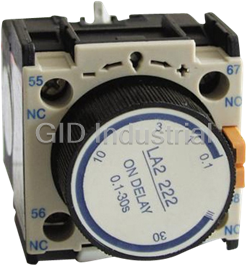
Schneider Electric LA2-DT2 Timer Block; .01-30 Seconds Time Delay On
Part Number
LA2-DT2
Price
Request Quote
Manufacturer
SCHNEIDER ELECTRIC
Lead Time
Request Quote
Category
Timers
Specifications
Electricity Type
AC
Number of Pole
1
Phase
1
Size
Miniature
Theory
Time Relay
Type
AC Contactors
Datasheet

Extracted Text
Contactors d 3-pole contactors for motor control, 9 to 95 A Utilisation category AC-3 Control circuit : a.c. c Dimensions, mounting : References pages 1/44 to 1/48 Standard power ratings Rated Instantaneous Basic reference. Weight of 3-phase motors operational auxiliary Complete with code 50/60 Hz in category AC-3 current contacts indicating control (θ ≤ 55 °C) in AC-3 circuit voltage (2) up to Fixing, 1 220V 380V 660V 440V cabling (1) 230V 400V 415V 440V 500V 690V kW kW kW kW kW kW A kg 2.2 4 4 4 5.5 5.5 9 –– LC1-D0900ii (3) 0.320 1– LC1-D0910ii 0.320 –1 LC1-D0901ii 0.320 3 5.5 5.5 5.5 7.5 7.5 12 –– LC1-D1200ii (3) 0.320 1– LC1-D1210ii 0.320 –1 LC1-D1201ii 0.320 LC1-D0910ii 47.5 9910 10 18 –– LC1-D1800ii (3) 0.320 1– LC1-D1810ii 0.350 –1 LC1-D1801ii 0.350 5.5 11 11 11 15 15 25 –– LC1-D2500ii (3) 0.320 1– LC1-D2510ii 0.505 –1 LC1-D2501ii 0.505 7.5 15 15 15 18.5 18.5 32 –– LC1-D3200ii (3) 0.320 1– LC1-D3210ii 0.525 –1 LC1-D3201ii 0.525 LC1-D2510ii 11 18.5 22 22 22 30 40 11 LC1-D4011ii 1.150 15 22 25 30 30 33 50 11 LC1-D5011ii 1.150 18.5 30 37 37 37 37 65 11 LC1-D6511ii 1.150 22 37 45 45 55 45 80 11 LC1-D8011ii 1.500 25 45 45 45 55 45 95 (4) 1 1 LC1-D9511ii 1.500 Note : Add-on auxiliary contact blocks and modules : see pages 1/32 to 1/43. (1) For LC1-D09 to D32 : clip-on mounting onto 35 mm " rail AM1-DP. For LC1-D40 to D95 : clip-on mounting onto 35 mm or 75 mm " rail AM1-DL. LC1-D9511ii Power terminals : LC1-D09 to D95 protected against direct finger contact. Ready-to-tighten terminals. (2) Standard control circuit voltages (for other voltages, please consult your Regional customer centre). Volts c 24 42 48 110 220/230 230 240 380/400 400 415 440 500 660 50 Hz B5 D5 E5 F5 M5 P5 U5 Q5 V5 N5 R5 S5 Y5 60 Hz B6 D6 E6 F6 M6 – U6 Q6 – – R6 – – 50/60 Hz B7 D7 E7 F7 M7 P7 U7 Q7 V7 N7 R7 – – (3) 3-pole contactors without auxiliary contact (standard EN 50012). (4) 95 A rated operational current in AC-3 up to 400 V. Other versions Contactors with non-protected power terminals enabling “power” and “control” connections to be made using ring type terminals. Please consult your Regional customer centre. 1/18 Te Contactors d 3-pole contactors for motor control, 9 to 80 A Utilisation category AC-3 Control circuit : d.c. a Dimensions, mounting : References pages 1/44 to 1/48 Standard power ratings Rated Instantaneous Basic reference. Weight of 3-phase motors operational auxiliary Complete with code 50/60 Hz in category AC-3 current contacts indicating control (θ ≤ 55 °C) in AC-3 circuit voltage (2) up to Fixing, 1 220V 380V 660V 440V cabling (1) 230V 400V 415V 440V 500V 690V kW kW kW kW kW kW A kg 2.2 4 4 4 5.5 5.5 9 1– LP1-D0910ii 0.580 –1 LP1-D0901ii 0.580 3 5.5 5.5 5.5 7.5 7.5 12 1– LP1-D1210ii 0.580 –1 LP1-D1201ii 0.580 4 7.5 9 9 10 10 18 1– LP1-D1810ii 0.600 LP1-D0910ii –1 LP1-D1801ii 0.600 5.5 11 11 11 15 15 25 1– LP1-D2510ii 0.850 –1 LP1-D2501ii 0.850 7.5 15 15 15 18.5 18.5 32 1– LP1-D3210ii 0.880 –1 LP1-D3201ii 0.880 11 18.5 22 22 22 30 40 11 LP1-D4011ii 2.100 15 22 25 30 30 33 50 11 LP1-D5011ii 2.120 LP1-D3210ii 18.5 30 37 37 37 37 65 11 LP1-D6511ii 2.160 22 37 45 45 55 45 80 11 LP1-D8011ii 2.220 Note : Add-on auxiliary contact blocks and modules, see pages 1/32 to 1/43. (1) For LP1-D09 to D25 : clip-on mounting on 35 mm " rail AM1-DP. For LP1-D40 to D80 : clip-on mounting on 75 mm " rail AM1-DL. Power terminals : LP1-D09 to D80 protected against direct finger contact. Ready-to-tighten terminals. (2) Standard control circuit voltages (for other voltages, please consult your Regional customer centre). Volts a 12 24 36 48 60 72 110 125 220 250 440 U 0.8…1.1 Uc (3) JD BD CD ED ND SD FD GD MD UD RD U 0.7…1.25 Uc (4) JW BW CW EW – SW FW – MW – – (3) LP1-D40 to D80 : 0.85…1.1 Uc. (4) LP1-D40 to D80 : 0.75…1.2 Uc. Other versions Contactors with non-protected power terminals enabling “power” and “control” connections to be made using ring type terminals. Please consult your Regional customer centre. 1/19 Te Contactors d 3 and 4-pole contactors for heating, lighting, etc., 25 to 125 A Utilisation category AC-1 Control circuit : a.c. Dimensions, mounting : References pages 1/44 to 1/48 Non inductive loads Number Instantaneous Basic reference. Weight Maximum operational of poles auxiliary Complete with code current contacts indicating control Utilisation category AC-1 circuit voltage (2) (θ ≤ 55 °C) Fixing, 1 cabling (1) A N/O N/C kg 25 3––– LC1-D0900ii 0.320 – – or LC1-D1200ii (3) 0.320 1– LC1-D0910ii 0.320 1 – or LC1-D1210ii (3) 0.320 –1 LC1-D0901ii 0.320 – 1 or LC1-D1201ii (3) 0.320 LC1-D0910ii 4––– LC1-D12004ii 0.320 22 –– LC1-D12008ii 0.320 32 3––– LC1-D1800ii 0.320 1– LC1-D1810ii 0.350 –1 LC1-D1801ii 0.350 40 3––– LC1-D2500ii 0.320 1– LC1-D2510ii 0.505 –1 LC1-D2501ii 0.505 LC1-D12004ii 4––– LC1-D25004ii 0.505 22 –– LC1-D25008ii 0.505 50 3––– LC1-D3200ii 0.320 1– LC1-D3210ii 0.525 –1 LC1-D3201ii 0.525 60 3–11 LC1-D4011ii 1.150 4––– LC1-D40004ii 1.150 22 –– LC1-D40008ii 1.150 80 3–11 LC1-D5011ii 1.150 1 1 or LC1-D6511ii (3) 1.150 4––– LC1-D65004ii 1.150 LC1-D65004ii 22 –– LC1-D65008ii 1.150 125 3–11 LC1-D8011ii 1.500 1 1 or LC1-D9511ii (3) 1.500 4––– LC1-D80004ii 1.530 22 –– LC1-D80008ii 1.530 Note : Add-on auxiliary contact blocks and modules, see pages 1/32 to 1/43. (1) For LC1-D09 to D32 : clip-on mounting on 35 mm " rail AM1-DP. For LC1-D40 to D95 : clip-on mounting on 35 mm or 75 mm " rail AM1-DL. Power terminals : LC1-D09 to D95 protected against direct finger contact. Ready-to-tighten terminals. (2) Standard control circuit voltages (for other voltages, please consult your Regional customer centre). Volts c 24 42 48 110 220/230 230 240 380/400 400 415 440 500 660 50 Hz B5 D5 E5 F5 M5 P5 U5 Q5 V5 N5 R5 S5 Y5 60 Hz B6 D6 E6 F6 M6 – U6 Q6 – – R6 – – 50/60 Hz B7 D7 E7 F7 M7 P7 U7 Q7 V7 N7 R7 – – (3) Selection according to number of operating cycles. 1/20 Te Contactors d 3 and 4-pole contactors for heating, lighting, etc., 25 to 125 A Utilisation category AC-1 Control circuit : d.c. Dimensions, mounting : References pages 1/44 to 1/48 Non inductive loads Number Instantaneous Basic reference. Weight Maximum operational of poles auxiliary Complete with code current contacts indicating control Utilisation category AC-1 circuit voltage (2) (θ ≤ 55 °C) Fixing, 1 cabling (1) A N/O N/C kg 25 3–1– LP1-D0910ii 0.580 1 – or LP1-D1210ii (5) 0.580 –1 LP1-D0901ii 0.580 – 1 or LP1-D1201ii (5) 0.580 4––– LP1-D12004ii 0.580 22 –– LP1-D12008ii 0.580 32 3–1– LP1-D1810ii 0.600 LP1-D0910ii –1 LP1-D1801ii 0.600 40 3–1– LP1-D2510ii 0.850 –1 LP1-D2501ii 0.850 4––– LP1-D25004ii 0.850 22 –– LP1-D25008ii 0.850 50 3–1– LP1-D3210ii 0.880 –1 LP1-D3201ii 0.880 60 3–11 LP1-D4011ii 2.100 LP1-D3210ii 4––– LP1-D40004ii 2.100 22 –– LP1-D40008ii 2.100 80 3–11 LP1-D5011ii 2.120 1 1 or LP1-D6511ii (5) 2.160 4––– LP1-D65004ii 2.180 22 –– LP1-D65008ii 2.180 125 3–11 LP1-D8011ii 2.220 4––– LP1-D80004ii 2.250 22 –– LP1-D80008ii 2.250 Note : Add-on auxiliary contact blocks and modules, see pages 1/32 to 1/43. (1) For LP1-D12 to D32 : clip-on mounting on 35 mm " rail AM1-DP. For LP1-D40 to D80 : clip-on mounting on 75 mm " rail AM1-DL. Power terminals : LP1-D12 to D80 protected against direct finger contact. Ready-to-tighten terminals. (2) Standard control circuit voltages (for other voltages, please consult your Regional customer centre). Volts a 12 24 36 48 60 72 110 125 220 250 440 U 0.8…1.1 Uc (3) JD BD CD ED ND SD FD GD MD UD RD U 0.7…1.25 Uc (4) JW BW CW EW – SW FW – MW – – (3) For LP1-D40 to D80 : 0.85…1.1 Uc. (4) For LP1-D40 to D80 : 0.75…1.2 Uc. (5) Selection according to number of operating cycles. 1/21 Te Contactors d 3-pole reversing contactors for motor control, assembled by Telemecanique c 9 to 95 A (a.c. control circuit) and 9 to 32 A (d.c. control circuit). Utilisation category AC-3 or Dimensions, mounting : a pages 1/44 to 1/48 References 3-pole reversing contactors horizontally mounted (1) a.c. control circuit Standard power ratings Rated Instantaneous Basic reference. Weight 1 of 3-phase motors operational auxiliary Complete with code 50/60 Hz in category AC-3 current contacts indicating control in AC-3 per circuit voltage (2) up to contactor Fixing, 440V cabling (3) 220V 380V 660V 230V 400V 415V 440V 500V 690V kW kW kW kW kW kW A N/O N/C kg 2.2 4 4 4 5.5 5.5 9 –1 LC2-D0901ii ii ii ii ii 0.700 3 5.5 5.5 5.5 7.5 7.5 12 –1 LC2-D1201ii ii ii ii ii 0.700 4 7.5 9 9 10 10 18 –1 LC2-D1801ii ii ii ii ii 0.750 5.5 11 11 11 15 15 25 –1 LC2-D2501ii ii ii ii ii 1.100 7.5 15 15 15 18.5 18.5 32 –1 LC2-D3201ii ii ii ii ii 1.200 LC2-D1201ii 11 18.5 22 22 22 30 40 11 LC2-D4011ii ii ii ii ii 2.400 15 22 25 30 30 33 50 11 LC2-D5011ii ii ii ii ii 2.400 18.5 30 37 37 37 37 65 11 LC2-D6511ii ii ii ii ii 2.400 22 37 45 45 55 45 80 11 LC2-D8011ii ii ii ii ii 3.200 25 45 45 45 55 45 95 (up to 400V) 1 1 LC2-D9511ii ii ii ii ii 3.200 d.c. control circuit Standard power ratings Rated Instantaneous Basic reference. Weight of 3-phase motors operational auxiliary Complete with code 50/60 Hz in category AC-3 current contacts indicating control in AC-3 per circuit voltage (4) up to contactor Fixing, 440V cabling (5) 220V 380V 660V 230V 400V 415V 440V 500V 690V kW kW kW kW kW kW A N/O N/C kg 2.2 4 4 4 5.5 5.5 9 –1 LP2-D0901ii ii ii ii ii 1.200 3 5.5 5.5 5.5 7.5 7.5 12 –1 LP2-D1201ii ii ii ii ii 1.200 4 7.5 9 9 10 10 18 –1 LP2-D1801ii ii ii ii ii 1.270 5.5 11 11 11 15 15 25 –1 LP2-D2501ii ii ii ii ii 1.750 7.5 15 15 15 18.5 18.5 32 –1 LP2-D3201ii ii ii ii ii 1.850 LP2-D0901ii Accessories (to be ordered separately) Auxiliary contact blocks and add-on modules, see pages 1/32 to 1/43. (1) Fitted with pre-wired power circuit connections and mechanical interlock, without electrical interlocking. (2) Standard control circuit voltages (for other voltages, please consult your Regional customer centre). Volts c 24 42 48 110 220/230 230 240 380/400 400 415 440 500 660 50 Hz B5 D5 E5 F5 M5 P5 U5 Q5 V5 N5 R5 S5 Y5 60 Hz B6 D6 E6 F6 M6 – U6 Q6 – – R6 – – 50/60 Hz B7 D7 E7 F7 M7 P7 U7 Q7 V7 N7 R7 – – (3) For LC2-D09 to D32 : clip-on mounting on 35 mm " rail or screw fixing. For LC2-D40 to D95 : clip-on mounting on 35 mm or 75 mm " rail or screw fixing. Power terminals protected against direct finger contact and ready-to-tighten terminals. (4) Standard control circuit voltages (for other voltages, please consult your Regional customer centre). Uc (Volts) a 12 24 36 48 60 72 110 125 220 250 440 U 0.8 to 1.1 Uc standard coils JD BD CD ED ND SD FD GD MD UD RD U 0.7 to 1.25 Uc wide range coils JW BW CW EW – SW FW – MW – – (5) Clip-on mounting on 35 mm " rail or screw fixing. Power terminals protected against direct finger contact. Ready-to-tighten terminals. Other versions Reversing contactors fitted with mechanical interlock, with integral electrical interlocking. Please consult your Regional customer centre. 1/22 Te Contactors d 4-pole changeover contactors for distribution circuits, assembled by Telemecanique c 25 to 125 A (a.c. control circuit) and 25 and 40 A (d.c. control circuit). Utilisation category AC-1 or Dimensions, mounting : a pages 1/44 to 1/48 References 4-pole changeover contactors, horizontally mounted (1) a.c. control circuit Non inductive loads Instantaneous Basic reference. Weight 1 Maximum rated auxiliary Complete with code operational current contacts indicating control Utilisation category AC-1 per circuit voltage (θ < 55 °C) contactor Fixing, cabling (3) A N/O N/C kg 25 –– LC2-D12004ii 0.700 40 –– LC2-D25004ii 1.100 60 –– LC2-D40004ii 2.400 80 –– LC2-D65004ii 3.200 125 –– LC2-D80004ii 3.200 LC2-D12004ii 4-pole changeover contactors, horizontally mounted (1) d.c. control circuit Non inductive loads Instantaneous Basic reference. Weight Maximum rated auxiliary Complete with code operational current contacts indicating control Utilisation category AC-1 per circuit voltage (θ < 55 °C) contactor Fixing, cabling (5) A N/O N/C kg 25 –– LP2-D12004ii 1.200 40 –– LP2-D25004ii 1.750 Accessories (to be ordered separately) Auxiliary contact blocks and add-on modules, see pages 1/32 to 1/43. (1) Fitted with pre-wired power circuit connections and mechanical interlock, without electrical interlocking. Order separately 2 auxiliary contact blocks LA1-DNi1 to obtain electrical interlocking between the 2 contactors (see pages 1/33 to 1/37). (2) Standard control circuit voltages (for other voltages, please consult your Regional customer centre). Volts c 24 42 48 110 220/230 230 240 380/400 400 415 440 500 660 50 Hz B5 D5 E5 F5 M5 P5 U5 Q5 V5 N5 R5 S5 Y5 60 Hz B6 D6 E6 F6 M6 – U6 Q6 – – R6 – – 50/60 Hz B7 D7 E7 F7 M7 P7 U7 Q7 V7 N7 R7 – – (3) For LC2-D12 and D25 : clip-on mounting on 35 mm " rail or screw fixing. For LC2-D40 to D80 : clip-on mounting on 35 mm or 75 mm " rail or screw fixing. Power terminals protected against direct finger contact. Ready-to-tighten terminals. (4) Standard control circuit voltages (for other voltages, please consult your Regional customer centre). Uc (Volts) a 12 24 36 48 60 72 110 125 220 250 440 U 0.8 to 1.1 Uc standard coils JD BD CD ED ND SD FD GD MD UD RD U 0.7 to 1.25 Uc wide range coils JW BW CW EW – SW FW – MW – – For other voltages, please consult your customer centre. (5) Clip-on mounting on 35 mm " rail or screw fixing. Power terminals protected against direct finger contact. Ready-to-tighten terminals. Other versions Reversing contactors fitted with mechanical interlock, with integral electrical interlocking. Please consult your Regional customer centre. 1/23 Te Contactors d 3 and 4-pole contactors Components for assembling reversing contactors and changeover contactor pairs (horizontally mounted), for customer assembly Combinations Contactors Mechanical interlocks Set of power connections Assembled Without With integral 3-pole reversing contactors 4-pole changeover using 2 identical electrical interlocking electrical interlocking contactor pairs contactors (2 N/C contacts) 1 horizontally mounted, type : LC1-D09 LA9-D09978 LA9-D0902 LA9-D1269 LA9-D1270 LC1-D12 LA9-D1869 LA9-D2570 LC1-D18 LA9-D2569 LC1-D25 LA9-D3269 LC1-D32 LP1-D09 LP1-D12 LP1-D18 LP1-D25 LP1-D32 LC1-D40 LA9-D50978 LA9-D4002 LA9-D6569 LA9-D6570 LC1-D50 LC1-D65 LP1-D40 LP1-D50 LP1-D65 LC1-D80 LA9-D8069 LA9-D8070 LC1-D95 LP1-D80 LA9-D80978 LA9-D8002 LA9-D8069 LA9-D8070 1/24 Te A2 A1 2 1 L1 4 3 L2 L3 6 5 U 2 1 4 3 V W 6 5 A2 A1 A2 A1 2 1 1/L1 4 3 1/L2 5 1/L3 6 8 7 1N L1 2 1 2/L1 4 3 L2 2/L2 L3 6 5 2/L3 N 8 7 2N A2 A1 Contactors d 3 and 4-pole contactors Components for assembling reversing contactors and c changeover contactor pairs (horizontally mounted), or for customer assembly a Illustrations : References page 1/24 Component parts (including mechanical interlock with integral electrical interlocking) With Set of power connections Mechanical interlock 2 identical Reference Weight Kit reference Weight contactors (1) kg kg 1 For assembly of 3-pole reversing contactors for motor control LC1/LP1-D09iiii LA9-D1269 0.015 LA9-D0902 0.060 LC1/LP1-D12iiii LC1/LP1-D18iiii LA9-D1869 0.030 LA9-D0902 0.060 LC1/LP1-D25iiii LA9-D2569 0.030 LA9-D0902 0.060 LC1/LP1-D32iiii LA9-D3269 0.040 LA9-D0902 0.060 LC1/LP1-D4011ii LA9-D6569 0.290 LA9-D4002 0.170 LC1/LP1-D5011ii LC1/LP1-D6511ii LC1-D8011ii LA9-D8069 0.490 LA9-D4002 0.170 LP1-D8011ii LA9-D8069 0.490 LA9-D8002 0.170 LC1-D9511ii LA9-D8069 0.490 LA9-D4002 0.170 For assembly of 4-pole changeover contactor pairs for distribution (3-phase + neutral distribution system) LC1/LP1-D12004ii LA9-D1270 0.010 LA9-D0902 0.060 LC1/LP1-D25004ii LA9-D2570 0.020 LA9-D0902 0.060 LC1/LP1-D40004ii LA9-D6570 0.150 LA9-D4002 0.170 LC1/LP1-D65004ii LC1-D80004ii LA9-D8070 0.280 LA9-D4002 0.170 LP1-D80004ii LA9-D8070 0.280 LA9-D8002 0.170 Component parts (including mechanical interlock, without electrical interlocking) For assembly of 3-pole reversing contactors for motor control LC1/LP1-D0901ii LA9-D1269 0.015 LA9-D09978 0.030 LC1/LP1-D1201ii LC1/LP1-D1801ii LA9-D1869 0.030 LA9-D09978 0.030 LC1/LP1-D2501ii LA9-D2569 0.030 LA9-D09978 0.030 LC1/LP1-D3201ii LA9-D3269 0.040 LA9-D09978 0.030 LC1/LP1-D4011ii LA9-D6569 0.290 LA9-D50978 0.155 LC1/LP1-D5011ii LC1/LP1-D6511ii LC1-D8011ii LA9-D8069 0.490 LA9-D50978 0.155 LP1-D8011ii LA9-D8069 0.490 LA9-D80978 0.180 LC1-D9511ii LA9-D8069 0.490 LA9-D50978 0.155 For assembly of 4-pole changeover contactor pairs for distribution (3-phase + neutral distribution system) (2) LC1/LP1-D12004ii LA9-D1270 0.010 LA9-D09978 0.030 LC1/LP1-D25004ii LA9-D2570 0.020 LA9-D09978 0.030 LC1/LP1-D40004ii LA9-D6570 0.150 LA9-D50978 0.155 LC1/LP1-D65004ii LC1-D80004ii LA9-D8070 0.280 LA9-D50978 0.155 LP1-D80004ii LA9-D8070 0.280 LA9-D80978 0.180 (1) To order the 2 contactors : see pages 1/18 to 1/21. (2) Order 2 contact blocks LA1-DNi1 to obtain electrical interlocking. See pages 1/33 to 1/37. 1/25 Te Thermal overload relays d 3-pole thermal overload relays (class 10 A) adjustable from 0.1 to 93 A, for motor protection References Thermal overload relays to be used with fuses Thermal overload relays - compensated with manual or automatic reset, 1 - relay trip indicator, - for a.c. or d.c. Relay Fuses to be used For direct Reference Weight setting with selected relay mounting range Type beneath contactor aM gG (BS88) LC1, LP1 AA A kg Class 10 A (1) 0.10…0.16 0.25 2 D09…D32 LR2-D1301 0.165 0.16…0.25 0.5 2 D09…D32 LR2-D1302 0.165 0.25…0.40 1 2 D09…D32 LR2-D1303 0.165 0.40…0.63 1 4 D09…D32 LR2-D1304 0.165 0.63…1 2 4 D09…D32 LR2-D1305 0.165 1…1.6 2 6 D09…D32 LR2-D1306 0.165 1.6…2.5 4 10 D09…D32 LR2-D1307 0.165 2.5…4 6 16 D09…D32 LR2-D1308 0.165 LR2-D13ii 4…6 8 16 D09…D32 LR2-D1310 0.165 5.5…8 12 20 D09…D32 LR2-D1312 0.165 7…10 12 20 D09…D32 LR2-D1314 0.165 9…13 16 25 D12…D32 LR2-D1316 0.165 12…18 20 32 D18…D32 LR2-D1321 0.165 17…25 25 50 D25 and D32 LR2-D1322 0.165 23…32 40 63 D25 and D32 LR2-D2353 0.320 30...40 40 80 D32 LR2-D2355 0.320 17…25 25 50 D40…D95 LR2-D3322 0.510 23…32 40 63 D40…D95 LR2-D3353 0.510 30…40 40 80 D40…D95 LR2-D3355 0.510 37…50 63 100 D50…D95 LR2-D3357 0.510 48…65 63 100 D50…D95 LR2-D3359 0.510 LR2-D23ii 55…70 80 125 D65…D95 LR2-D3361 0.510 63…80 80 125 D80 and D95 LR2-D3363 0.510 80…93 100 160 D95 LR2-D3365 0.510 3-pole thermal overload relays for use with unbalanced loads Class 10 A : Change the prefix in the references above from LR2 to LR3. Example : LR3-D1301. (1) Standard IEC 947-4 specifies a tripping time for 7.2 times the setting current I : R class 10 A : between 2 and 10 seconds. Other versions Thermal overload relays - for distribution circuits, - with flat terminals for ring type connectors (except LR2-D3365). LR2-D33ii Please consult your Regional customer centre. LR2, LR3-D1 Independent mounting on 50 mm centres Independent mounting on 110 mm centres Remote trip or electrical reset or on rail AM1-DP200 or DE200 46 LA7-D1064 = = 45 LA7-D1064 = 35 = LA7-D03 (1) 96 34 98 d 2xŞ4,5 8 17 108 DX1-AP25 2xŞ6,5 AM1-DP200 AM1-DE200 d 2 9.5 (1) Can be mounted on RH or LH (1) + 5 mm for LR2-D15ii side of relays LR2, LR3-D1 1/26 Te 43,5 79 4 50/60(1) 125 = 110 = Thermal overload relays d 3-pole thermal overload relays (class 20) adjustable from 0.1 to 93 A, for motor protection References Thermal overload relays to be used with fuses Thermal overload relays - compensated with manual or automatic reset, 1 - relay trip indicator, - for a.c. or d.c. Relay Fuses to be used For direct Reference Weight setting with selected relay mounting range Type beneath contactor aM gG (BS88) LC1, LP1 AA A kg LR2-D15ii ii ii ii ii Class 20 (1) 2.5…4 6 16 D09…D32 LR2-D1508 0.190 4…6 8 16 D09…D32 LR2-D1510 0.190 5.5…8 12 20 D09…D32 LR2-D1512 0.190 7…10 16 25 D09…D32 LR2-D1514 0.190 9…13 16 25 D12…D32 LR2-D1516 0.190 12…18 25 40 D18…D32 LR2-D1521 0.190 17…25 32 50 D25 and D32 LR2-D1522 0.190 23…32 40 63 D25 and D32 LR2-D2553 0.345 LR2-D25ii ii ii ii ii 17…25 32 50 D40…D95 LR2-D3522 0.535 23…32 40 63 D40…D95 LR2-D3553 0.535 30…40 50 80 D40…D95 LR2-D3555 0.535 37…50 63 100 D50…D95 LR2-D3557 0.535 48…65 80 100 D50…D95 LR2-D3559 0.535 55…70 100 125 D65…D95 LR2-D3561 0.535 63…80 100 125 D80 and D95 LR2-D3563 0.535 (1) Standard IEC 947-4 specifies a tripping time for 7.2 times the setting current I : R class 20 : between 6 and 20 seconds. Other versions Thermal overload relays - for distribution circuits, - with flat terminals for ring type connectors. Please consult your Regional customer centre. LR2-D35ii ii ii ii ii LR2, LR3-D2 Independent mounting on 50 mm centres Independent mounting on 110 mm centres Remote trip or electrical reset device or on rail AM1-DP200 or DE200 57 LA7-D2064 = = 55 LA7-D2064 = 40 = LA7-D03 (1) 96 29 98 d 2xŞ4,5 13 22 108 DX1-AP26 2xŞ6,5 AM1-DP200 AM1-DE200 (1) Can be mounted on RH or LH d 2 9.5 side of relays LR2, LR3-D2 LR2, LR3-D3 Independent mounting on 50 mm centres Independent mounting on 110 mm centres Remote trip or electrical reset device or on rail AM1-DP200 or DE200 LA7-D902 75 75 = = LA7-D3064 LA7-D3064 = 50 = LA7-D03 (1) 3xŞ6,5 119 21 121 d 2xŞ4,5 23,5 131 == 40 32 AM1-DP200 AM1-DE200 (1) Can be mounted on RH or LH side d 2 9.5 of relays LR2-D, LR3-D3 1/27 Te 43,5 51,5 90 100 2 3 50/60 75/87 125 126 = 110 = 110 1 LA7-D1064 DX1-AP25 LA7-D305 LR2-D LA7-D03 LR2-D1 LR3-D1 LA7-D03 LA7-D2064 LA7-D901 DX1-AP26 ZA2-BZ13 LR2-D LA7-D1020 LR2-D2 LR3-D2 ZA2-BL432 LA7-D3064 ZA2-BZ13 LA7-D902 LA7-D1020 ZA2-BA639 LR2-D3 LR3-D3 1/28 Te R R Thermal overload relays d 3-pole thermal overload relays adjustable from 0.1 to 93 A References Illustrations : page 1/28 Accessories (to be ordered separately) Description For use on Sold in Unit Weight overload relays lots of reference kg Terminal blocks (1) LR2-D1 1 LA7-D1064 0.100 1 for clip-on mounting on LR3-D1 35 mm rail (AM1-DP200) LR2-D2 1 LA7-D2064 0.120 or screw fixing. LR3-D2 See pages 1/26 and 1/27 LR2-D3 1 LA7-D3064 (2) 0.205 for fixing centres LR3-D3 Power terminals adaptor LR2-D1 1 LA7-D1058 0.080 for mounting an LRi-D13 LR3-D1 overload relay beneath an LC1-D40, D50 or D65 contactor Mounting plates (3) LR2-D1 10 DX1-AP25 0.065 for screw fixing LR3-D1 on 110 mm centres LR2-D2 10 DX1-AP26 0.082 LR3-D2 LR2-D3 1 LA7-D902 0.130 LR3-D3 Marker holder LR2-D 100 LA7-D903 0.001 snap-in LR3-D Bag of 400 labels – 1 LA9-D91 0.001 (blank, self-adhesive) 7 x 16 mm Locking device LR2-D 10 LA7-D901 0.005 for “Stop” button LR3-D Remote tripping and LR2-D 1 LA7-D03i (5) 0.090 electrical reset device (4) LR3-D Remote control “Reset” function By flexible cable LR2-D 1 LA7-D305 0.075 (length = 0.5 m) LR3-D “Stop” and/or “Reset” function For fitting, remove the terminal protection shrouds and order the following 3 products : Adaptor LR2-D 1 LA7-D1020 0.005 for door mounted operator LR3-D Rod (snap-off end to obtain required LR2-D 10 ZA2-BZ13 0.100 length between 17 and 120 mm) LR3-D Operating head LR2-D 1 ZA2-Biiii (6) 0.012 for spring return pushbutton LR3-D (1) Terminal blocks are supplied with terminals protected against direct finger contact. Ready-to-tighten screws. (2) With terminals for ring type connectors, the reference becomes LA7-D30646. (3) Remember to order the terminal block corresponding to the overload relay size. (4) The time for which the coil of remote tripping and electrical resetting device LA7-D03 can remain energised depends on its rest time : 1 s pulse duration with 9 s rest time ; 5 s pulse duration with 30 s rest time ; 10 s pulse duration with 90 s rest time ; maximum pulse duration of 20 s with a rest time of 300 s. Minimum impulse time : 200 ms. (5) Reference to be completed by adding the coil voltage code. Standard control circuit voltages (for other voltages, please consult your Regional customer centre). Volts c 12 24 48 96 110 220/230 380/400 415/440 50/60 Hz – B E – F M Q N Consumption, inrush and sealed : < 100 VA Volts a J BEDD F M – – Consumption, inrush and sealed : < 100 W. (6) Reference to be completed, please refer to chapter 5. LA7-D1020 LA7-D305 Adaptor for door mounted operator “Reset” by flexible cable Mounting with cable straight Mounting with cable bent Stop Reset LA7-D305 c 10 e c LA7-D1020 e M10x1 c : adjustable from 17 to 120 mm c : up to 550 mm e : up to 20 mm e : up to 20 mm 1/29 Te A Thermal overload relays d 3-pole thermal overload relays adjustable from 0.1 to 93 A Scheme, setting-up References : pages 1/26 to 1/29 Scheme LR2-D LR3-D Auto. 1 RESET { Man. TEST STOP Setting-up the special functions of LR2-D and LR3-D thermal overload relays Setting the relay “Manual-Automatic” selection 4 7 2 LR2 D 13 5 A 1 M U T 6 4 O TEST STOP RESET 3 NO NC 98 97 95 96 “Manual” reset “Automatic” reset i Lift the transparent cover 1 to gain access to the settings and controls. i After having lifted the transparent cover, the type of reset operation can be i Adjustment is achieved by turning dial 2 which is graduated directly in selected by turning the blue “RESET” selector 4 : Amperes. - turn to the left for manual reset, i The setting can be locked by sealing 3 of the cover. - push and turn to the right for automatic reset. The selector is then held in the automatic position and is released by turning the selector to the left (return to manual operation). i With the cover folded down, the selector is locked. i Manual resetting of the relay is achieved by pressing the blue “RESET” button. “Stop” function 5 “Test” function 6 Stop Locking Test Trip indicator i The “Stop” function is obtained by pressing the red “STOP” button 5. i The “Test” function is obtained by pressing the red “TEST” button 6 with a i Pressing the “STOP” button : screwdriver. - actuates the N/C contact, i Operation of the “TEST” button simulates tripping of the relay and : - does not affect the N/O contact. - actuates both N/O and N/C contacts, i The “STOP” button can be locked by fitting a “U” clip (ref. LA7-D901). - actuates the trip indicator 7. With the cover folded down, the device is locked. 1/30 Te A U T O RESET A U T O RESET A U T O ET A U T O RESET TEST STOP 5,5 8 6 2 1 4 3 6 5 96 95 98 97 7 Thermal overload relays d 3-pole thermal overload relays adjustable from 0.1 to 93 A Dimensions References : pages 1/26 and 1/27 LR2, LR3-D1 Direct mounting beneath contactors LC1-D09 to D32, LP1-D09 to D32 and LP4-D12 1 AM1-DP200 AM1-DE200 d 2 9.5 b (1) c e g LC1-D09, D12, D18 81 98 50 0 LC1-D25 86 108 55 10.7 92 8 LC1-D32 86 109 55 8.1 c d 17 LP1-D09, D12, D18 81 133 50 0 44 g LP1-D25 86 152 55 10.7 LP1-D32 86 153 55 8.1 LP4-D12 81 98 50 0 (1) + 5 mm for LR2-D15ii LR2, LR3-D2 Direct mounting beneath contactors LC1-D25 and D32, LP1-D25 and D32 AM1-DP200 AM1-DE200 d 2 9.5 bc e g 92 13 LC1-D25 97.5 98 60 1.5 c d 22 LC1-D32 97.5 98 60 0.5 54 g LP1-D25 97.5 155 60 1.5 LP1-D32 97.5 155 60 0.5 LR2, LR3-D3 Direct mounting beneath contactors LC1-D40 to D95 and LP1-D40 to D80 AM1-DL201 AM1-DL200 d7 17 b c e g (3P) g (4P) LC1-D40 111 119 72.4 4.5 13 LC1-D50 111 119 72.4 4.5 – LC1-D65 111 119 72.4 4.5 13 LC1-D80 115.5 124 76.9 9.5 22 LC1-D95 115.5 124 76.9 9.5 – 109 21 LP1-D40 111 176 72.4 4.5 13 4 c d 30 LP1-D50 111 176 72.4 4.5 – 70 g LP1-D65 111 176 72.4 4.5 13 LP1-D80 115.5 179.4 76.9 9.5 22 1/31 Te 54 59 47(1) b b b e e e 1 LA6-DK LA8-DN LC1-D09, D12, D18 LA8-DN LA1-DN LA1-DN10, DN01 LA1-DN, DC LC1-D25, D32 LA2-DT, DS LC1-D40, D50, D65, D80, D95 LA3-DR LA1-DX, DY, DZ 1/32 Te Contactors d 3 and 4-pole contactors, reversing and changeover contactors Auxiliary contact blocks and accessories Control circuit : a.c. Illustrations : References page 1/32 Instantaneous auxiliary contact blocks (1) For use in normal operating environments Number Max. number of blocks per contactor Composition Reference Weight 1 of Clip-on mounting contacts Front Side kg 1 1 (D25 and D32) – – – 1 – LA1-DN10 0.020 or 2 (D40…D95) –1 LA1-DN01 0.020 2 1 (D09…D95) – – – 1 1 LA1-DN11 0.030 2– LA1-DN20 0.030 –2 LA1-DN02 0.030 – 2 (D09…D95) – – 1 1 LA8-DN11 0.030 2– LA8-DN20 0.030 4 1 (D09…D95) – – – 2 2 LA1-DN22 0.050 13 LA1-DN13 0.050 4– LA1-DN40 0.050 –4 LA1-DN04 0.050 31 LA1-DN31 0.050 2 2 (2) LA1-DC22 0.050 With terminal referencing conforming to standard EN 50012 2 1 (D0910…D3210) – – – 1 1 LA1-DN11M 0.030 1 (D0900…D3200) – – – 1 1 LA1-DN11P 0.030 1 (D40…D95) – – – 1 1 LA1-DN11G 0.030 4 1 (D0910…D3210) – – – 2 2 LA1-DN22M 0.050 1 (D0900…D3200) – – – 2 2 LA1-DN22P 0.050 1 (D40…D95) – – – 2 2 LA1-DN22G 0.050 Instantaneous auxiliary contact blocks with dust and damp protected contacts (1) For use in harsh industrial environments 2 1 (D09…D95) – 2 – – – LA1-DX20 0.040 – 2 (3)– – LA1-DY20 0.040 4 1 (D09…D95) – 2 – 2 – LA1-DZ40 0.050 2–1 1 LA1-DZ31 0.060 (1) Maximum mounting capacity, depending on type of coil. Device Coil Operation Maximum number of add-on blocks type type guaranteed Clip-on mounting from front side LC1-D 50 or 60 Hz 0.8…1.1 Uc 1 + 2 50/60 Hz 0.8…1.1 Uc 1 or 2 0.85…1.1 Uc 1 + 2 (2) Including 1 N/O and 1 N/C make before break. (3) Device fitted with 4 terminals for earth screen continuity. 1/33 Te 1 LA6-DK LA8-DN LC1-D09, D12, D18 LA8-DN LA1-DN LA1-DN10, DN01 LA1-DN, DC LC1-D25, D32 LA2-DT, DS LC1-D40, D50, D65, D80, D95 LA3-DR LA1-DX, DY, DZ 1/34 Te Contactors d 3 and 4-pole contactors, reversing and changeover contactors Auxiliary contact blocks and accessories Control circuit : a.c. Illustrations : References page 1/34 Time delay auxiliary contact blocks (1) Number Maximum number of Time delay Reference Weight of blocks per contactor Type Setting contacts Front clip-on mounting range kg 1 1 N/O 1 (D09…D95) On-delay 0.1…3 s (2) LA2-DT0 0.060 + 1 N/C 0.1…30 s LA2-DT2 0.060 10…180 s LA2-DT4 0.060 1…30 s (3) LA2-DS2 0.060 Off-delay 0.1…3 s (2) LA3-DR0 0.060 0.1…30 s LA3-DR2 0.060 10…180 s LA3-DR4 0.060 Mechanical latch blocks (1) Unlatching Clip-on Basic reference. Weight control front mounting To be completed (4) kg Manual LC1-D09…D65 LA6-DK10i i i i i 0.070 or electric LC1-D80…D95 LA6-DK20i i i 0.090 i i (1) Maximum mounting capacity, depending on type of coil. Device Coil Operation Maximum number of add-on blocks type type guaranteed Clip-on mounting from front side LC1-D 50 or 60 Hz 0.8…1.1 Uc 1 + 2 50/60 Hz 0.8…1.1 Uc 1 or 2 0.85…1.1 Uc 1 + 2 (2) With extended scale from 0.1 to 0.6 s. (3) With switching time of 40 ms ± 15 ms between opening of the N/C contact and closing of the N/O contact. (4) Standard control circuit voltages (for other voltages, please consult your Regional customer centre). Volts c or a 12 24 32/36 42/48 60/72 100 110/127 220/240 255/277 380/415 Code J B C E EN K F M U Q 1/35 Te 1 LA6-DK LA8-DN LP1-D09, D12, D18 LA8-DN LA1-DN LA1-DN10 LA1-DN01 LA1-DN, DC LP1-D25, D32 LA2-DT, DS LA3-DR LP1-D40, D50, D65, D80 LA1-DX, DY, DZ 1/36 Te Contactors d 3 and 4-pole contactors, reversing and changeover contactors Auxiliary contact blocks and accessories Control circuit : d.c. Illustrations : References page 1/36 Instantaneous auxiliary contact blocks (1) For use in normal operating environments Number Max. number of blocks per contactor Composition Reference Weight 1 of Clip-on mounting contacts Front Side kg 1 1 (D25 and D32) – – – 1 – LA1-DN10 0.020 2 (D40…D80) – 1 LA1-DN01 0.020 2 1 (D09…D80) – – – 1 1 LA1-DN11 0.030 2– LA1-DN20 0.030 –2 LA1-DN02 0.030 2 (D09…D32) – – – 1 1 LA8-DN11 0.030 2– LA8-DN20 0.030 4 1 (D09…D80) – – – 2 2 LA1-DN22 0.050 13 LA1-DN13 0.050 4– LA1-DN40 0.050 –4 LA1-DN04 0.050 31 LA1-DN31 0.050 2 2 (2) LA1-DC22 0.050 Instantaneous auxiliary contact blocks with dust and damp protected contacts (1) For use in harsh industrial environments 2 1 (D09…D80) – 2 – – – LA1-DX20 0.040 2 2 (3)– – LA1-DY20 0.040 4 1 (D09…D80) – 2 – 2 – LA1-DZ40 0.050 2–1 1 LA1-DZ31 0.060 Time delay auxiliary contact blocks (1) Number Max. number of blocks per contactor Time delay Reference Weight of Clip-on mounting Type Setting contacts Front Side range(s) kg 1 N/O 1 (D09…D80) – On 0.1…3 (4) LA2-DT0 0.060 + delay 1 N/C 0.1…30 LA2-DT2 0.060 10…180 LA2-DT4 0.060 1…30 (5) LA2-DS2 0.060 Off 0.1…3 (4) LA3-DR0 0.060 delay 0.1…30 LA3-DR2 0.060 10…180 LA3-DR4 0.060 Mechanical latch blocks (Manual or electric unlatching control) Front clip-on Basic reference. Weight mounting To be completed (6) kg LP1-D09…D65 LA6-DK10i i i 0.070 i i LP1-D80 LA6-DK20i i i i i 0.090 (1) Either of the following may be fitted, as required: 2 side-mounting contact blocks or 1 front mounting contact block. (2) Including 1 N/O + 1 N/C make before break. (3) Device fitted with 4 terminals for earth screen continuity. (4) With extended scale from 0.1 to 0.6 s. (5) With switching time of 40 ms ± 15 ms between opening of the N/C contact and closing of the N/O contact. (6) Standard control circuit voltages (for other voltages, please consult your Regional customer centre). Volts c or a 12 24 32/36 42/48 60/72 100 110/127 220/240 255/277 380/415 Code J B C E EN K F M U Q 1/37 Te 1 LA4-DT LA4-DR LA4-DF LA4-DL LA4-DW LA4-DM LC1-D09, D12, D18 LC1-D25, D32 LC1-D40, D50, D65, D80, D95 LA4-DV LA4-DT LA4-DF LA4-DL LA4-DM LP1-D09, D12, D18 LP1-D25, D32 LP1-D40, D50, D65, D80 LA4-DV 1/38 Te Contactors d 3 and 4-pole contactors, reversing and changeover contactors Accessories References Illustrations : page 1/38 Electronic serial timer modules (1) Operational voltage (2) Time delay Reference Weight c LC1- a LP1- 24…250 V 100…250 V 24…250 V kg 1 On-delay type D09…D32 D40…D95 D09…D32 0.1…2 s LA4-DT0U 0.040 1.5…30 s LA4-DT2U 0.040 25…500 s LA4-DT4U 0.040 Off-delay type D09…D18 D25…D95 – 0.1…2 s LA4-DR0U 0.050 1.5…30 s LA4-DR2U 0.050 25…500 s LA4-DR4U 0.050 Interface modules (1) Operational voltage Supply Reference Weight c LC1- a LP1- voltage 24…250 V 100…250 V 380…415 V 24…250 V E1-E2 (a)kg Relay interface – – D09…D95 – 24 V LA4-DFBQ 0.055 D09…D95 – – D09…D32 24 V LA4-DFB 0.050 48 V LA4-DFE 0.050 Relay interface with manual override switch (output forced “ON”) D09…D95 – – D09…D32 24 V LA4-DLB 0.045 48 V LA4-DLE 0.045 Solid state interface D09…D32 D40…D95 – – 24 V LA4-DWB 0.045 Auto-Man-Stop control modules (1) For local override operation tests with 2-position “Auto-Man” switch and “O-I” switch Operational voltage Reference Weight c LC1- a LP1- 24…100 V 100…250 V 24…100 V 100…250 V kg D09…D95 – D09…D32 – LA4-DMK 0.040 – D09…D95 – D09…D32 LA4-DMU 0.040 Indicators (contactor state) Red LED For mounting on contactors Supply Sold in Unit Weight LC1 and LP1 voltage (c and a) lots of reference kg Clips into 12…72 V 5 LA4-DVE 0.010 legend plate location on all contactor sizes 72…250 V 5 LA4-DVM 0.010 250…440 V 5 LA4-DVR 0.010 (1) Mounted at top on terminals A1 and A2 (screw fixing). (2) For 24 V operation, the contactor must be fitted with a 21 V coil (code Z). See pages 1/49 to 1/52. 1/39 Te LA4-Dl1 LA4-Dl2 1 LC1-D09, D12, D18 LC1-D25, D32 LC1-D40, D50, D65, D80, D95 LA4-Dl1 LA4-Dl3 LA4-Dl2 LP1-D09, D12, D18 LP1-D25, D32 LP1-D40, D50, D65, D80 1/40 Te Contactors d 3 and 4-pole contactors, reversing and changeover contactors Accessories References Illustrations : page 1/40 Coil suppressor modules RC circuits (resistor-capacitor) (1) Mounted at top For use with contactor (2) Reference Weight 1 of contactor on Rating Type coil terminals A1 and A2 c LC1- a LP1- VV kg Clip-on fixing and electrical D09…D32 24…48 – LA4-DA1E 0.012 connection. Fitting of an input 50…127 – LA4-DA1G 0.012 module is still possible. 110…240 – LA4-DA1U 0.012 Screw fixing D09…D95 24…48 – LA4-DA2E 0.018 50…127 – LA4-DA2G 0.018 110…240 – LA4-DA2U 0.018 380…415 – LA4-DA2N 0.018 Varistors (peak limiting) (3) Clip-on fixing and electrical D09…D32 24…48 24…48 LA4-DE1E 0.012 connection. Fitting of an input 50…127 50…127 LA4-DE1G 0.012 module is still possible. 110…250 110…250 LA4-DE1U 0.012 Screw fixing D09…D32 24…48 24…48 LA4-DE2E 0.018 50…127 50…127 LA4-DE2G 0.018 110…250 110…250 LA4-DE2U 0.018 D40…D95 24…48 – LA4-DE2E 0.018 50…127 – LA4-DE2G 0.018 110…250 – LA4-DE2U 0.018 D40…D80 – 24…48 LA4-DE3E 0.018 – 50…127 LA4-DE3G 0.018 – 110…250 LA4-DE3U 0.018 Diodes (4) Clip-on fixing and electrical D09…D32 – 12…250 LA4-DC1U 0.012 connection. Fitting of an input module is still possible. Screw fixing D09…D32 – 12…250 LA4-DC2U 0.018 D40…D80 – 24…250 LA4-DC3U 0.018 Bidirectional peak limiting diode (5) Clip-on fixing and electrical D09…D32 24 24 LA4-DB1B 0.012 connection. Fitting of an input module is still possible. 72 72 LA4-DB1S 0.012 Screw fixing D09…D32 24 24 LA4-DB2B 0.018 72 72 LA4-DB2S 0.018 D40…D95 24 – LA4-DB2B 0.018 72 – LA4-DB2S 0.018 D40…D80 – 24 LA4-DB3B 0.018 –72 LA4-DB3S 0.018 (1) Effective protection for circuits highly sensitive to “high frequency” interference. Voltage limited to 3 Uc max and oscillating frequency limited to 400 Hz max. Slight increase in drop-out time (1.2 to 2 times the normal time). (2) For satisfactory protection, a suppressor module must be fitted across the coil of each contactor (3) Protection provided by limiting the transient voltage to 2 Uc max. Maximum reduction of transient voltage peaks. Slight increase in drop-out time (1.1 to 1.5 times the normal time). (4) No overvoltage or oscillating frequency. Increase in drop-out time (6 to 10 times the normal time). Polarised component. (5) Protection provided by limiting the transient voltage to 2 Uc max. Maximum reduction of transient voltage peaks. 1/41 Te 1 LA9-D1860 LA9-D80961 LA9-D1260 LA9-D40961 LA9-D3260 LA9-D2560 LA9-D80962 LA9-D1261 LA9-D40963 LA9-D2561 LA9-D80963 LA9-D1262 LA9-D8067 LA9-D6567 LA9-D2563 LC1-D32 LA9-D1263 LP1-D32 LC1-D18 LP1-D18 LC1-D80, D95 LP1-D80 LC1-D40, D50, D65 LP1-D40, D50, D65 LC1-D25 LA9-D92 LP1-D25 LA9-D93 LC1-D09, D12 LP1-D09, D12 LA9-D941 1/42 Te Contactors d 3 and 4-pole contactors, reversing and changeover contactors Accessories References Illustrations : page 1/42 Accessories for main pole and control connections Description For use on contactors Sold in Unit Weight c LC1- a LP1- lots of reference kg 1 Connectors 4-pole D09, D12 D09, D12 1 LA9-D1260 0.030 2 for cable 10 mm sizes : 3-pole D18 D18 1 LA9-D1860 0.035 2 25 mm D2500, D32 D32 1 LA9-D3260 0.040 4-pole D25 D25 1 LA9-D2560 0.050 2 25 mm Links for 2 poles D09, D12 D09, D12 10 LA9-D1261 0.012 parallel connection of D25 D25 10 LA9-D2561 0.060 D40…D65 D40…D65 2 LA9-D40961 0.021 D80, D95 D80 2 LA9-D80961 0.060 3 poles D09, D12 D09, D12 10 LA9-D1262 0.003 (star connection) D80, D95 D80 1 LA9-D80962 0.080 4-pole D09, D12 D09, D12 2 LA9-D1263 0.024 D25 D25 2 LA9-D2563 0.017 D40…D65 D40…D65 2 LA9-D40963 0.070 D80, D95 D80 2 LA9-D80963 0.100 Staggered coil connection – D40…D80 10 LA9-D09966 0.006 Control circuit take-off – D40…D65 10 LA9-D6567 0.010 from main pole D80 10 LA9-D8067 0.010 Accessories for protection and marking Description For use on Sold in Unit Weight Contactors Add-on lots of reference c LC1- a LP1- blocks kg Miniature fuse holder D09…D95 D09…D80 – 1 LA9-D941 0.025 type 5 x 20 with 4 A - 250 V fuse Legend holder D09…D95 D09…D80 LA1-D 100 LA9-D92 0.001 8 x 22 mm snap-in (4 contacts) LA2-D, LA3-D LA6-DK Legend holder – – LA1-DN 100 LA9-D90 0.001 8 x 17 mm snap-in (2 contacts) Bag of 300 labels D09…D95 D09…D80 LA1-D 1 LA9-D93 0.001 (blank, self-adhesive) (4 contacts) 7 x 21 mm LA2-D, LA3-D LA6-DK Bag of 400 labels – – LA1-DN 1 LA9-D91 0.001 (blank, self-adhesive) 7 x 16 mm (2 contacts) Sealing cover – – LA2, LA3-D 1 LA9-D901 0.005 Accessories for mounting Adaptor for mounting on ’ rail D09…D32 D09…D32 – 1 LA9-D973 0.025 Mounting plates for fixing on 2 ’ rails D09…D18 D09…D18 – 10 DX1-AP25 0.065 (120 mm fixing centres) D25…D32 D25…D32 – 10 DX1-AP26 0.082 Set of shims for fitting side-mounting blocks LA8-DN on LC1-D40 to D95 1 LA9-D511 0.020 1/43 Te Contactors d 3 and 4-pole contactors, type LC1-D Dimensions References : pages 1/18 and 1/20 LC1-D09, D12 LC1-D18 LC1-D2500 44 44 Minimum electrical Minimum electrical 1 LA4 clearance clearance LA4 10 85 12,5 45 12,5 10 93 12,5 45 12,5 (LA8) (LA8) (LA8) (LA8) 118(2)(LA1) 113(2)(LA1) 128(LA6-DK1) 136(LA6-DK1) 137(1) (LA2,LA3,LA6-DK2) 145(1) (LA2,LA3,LA6-DK2) (1) + 4 mm with lead sealing kit (1) + 4 mm with lead sealing kit (2) With 2 or 4 contacts (2) With 2 or 4 contacts (3) With or without combined use of a coil suppressor module (3) With or without combined use of a coil suppressor module LA4-DA1, DE1 LA4-DA1, DE1 LC1-D2510, D2501, D25004 LC1-D32 = 44 = = 44 = Minimum electrical Minimum electrical LA4 LA4 clearance clearance 10 93 12,5 56 12,5 10 98 12,5 56 12,5 (LA8) (LA8) (LA8) (LA8) 126(2)(LA1) 131(2)(LA1) 136(LA6-DK1) 141(LA6-DK1) 145(1) (LA2,LA3,LA6-DK2) 150(1) (LA2,LA3,LA6-DK2) (1) + 4 mm with lead sealing kit (1) + 4 mm with lead sealing kit (2) With 2 or 4 contacts; 1 contact = 120 (LA1-DN10 or DN01) (2) With 2 or 4 contacts; 1 contact = 125 (LA1-DN10 or DN01) (3) With or without combined use of a coil suppressor module (3) With or without combined use of a coil suppressor module LA4-DA1, DE1 LA4-DA1, DE1 LC1-D40, D50, D65 LC1-D80, D95 32 44 28 44 Minimum electrical Minimum electrical LA4 LA4 clearance clearance 12 114(4) 12 125(4) 12,5 (3) 12,5 12,5 (3) 12,5 145(2)(LA1) 153(2)(LA1) (LA8) (LA8) (LA8) (LA8) 172(1)(LA2,LA3,LA6-DK2) 164(1)(LA2,LA3,LA6-DK2) (1) + 4 mm with lead sealing kit (1) + 4 mm with lead sealing kit (2) With 2 or 4 contacts; 1 contact = 139 (LA1-DN10 or DN01) (2) With 2 or 4 contacts; 1 contact = 147 (LA1-DN10 or DN01) (3) 75 : 3 poles, 85 : 4 poles (3) 85 : 3 poles, 96 : 4 poles (4) 125 : LC1-Dii008 (4) 140 : LC1-Dii008 1/44 Te 127 74 84 135(Di2) 77(Di1) 142(DF,DT) 87(Di1) 90(Di2) 150(DM,DR,DW,DL) 100(Di2) 97(3)(DF,DT) 107(3)(DF,DT) 105(3) (DM,DR,DW,DL) 115(3) (DM,DR,DW,DL) 127 74 84 77(Di1) 135(Di2) 87(Di1) 90(Di2) 142(DF,DT) 100(Di2) 150(DM,DR,DW,DL) 97(3)(DF,DT) 107(3)(DF,DT) 105(3) (DM,DR,DW,DL) 115(3) (DM,DR,DW,DL) Contactors d 3 and 4-pole contactors, type LP1-D Dimensions References : page 1/19 and 1/21 LP1-D09, D12 LP1-D18 44 44 Minimum electrical Minimum electrical LA4 LA4 1 clearance clearance 10 115 12,5 45 12,5 10 120 12,5 45 12,5 (LA8) (LA8) (LA8) (LA8) 148(2)(LA1) 153(2)(LA1) 158(LA6-DK1) 163(LA6-DK1) 167(1)(LA2,LA3,LA6-DK2) 172(1)(LA2,LA3,LA6-DK2) (1) + 4 mm with lead sealing kit (1) + 4 mm with lead sealing kit (2) With 2 or 4 contacts (2) With 2 or 4 contacts (3) With or without combined use of a coil suppressor module (3) With or without combined use of a coil suppressor module LA4-DC1, DE1. LA4-DC1, DE1. LP1-D25 LP1-D32 = 44 = = 44 = Minimum electrical Minimum electrical LA4 LA4 clearance clearance 10 130 10 135 12,5 56 12,5 12,5 56 12,5 (LA8) (LA8) (LA8) (LA8) 163(2)(LA1) 168(2)(LA1) 173(LA6-DK1) 178(LA6-DK1) 182(1)(LA2,LA3,LA6-DK2) 187(1)(LA2,LA3,LA6-DK2) (1) + 4 mm with lead sealing kit (1) + 4 mm with lead sealing kit (2) With 2 or 4 contacts; 1 contact : 157 (LA1-DN10 or DN01) (2) With 2 or 4 contacts; 1 contact : 162 (LA1-DN10 or DN01) (3) With or without combined use of a coil suppressor module (3) With or without combined use of a coil suppressor module LA4-DC1, DE1. LA4-DC1, DE1. LP1-D40, D50, D65 LP1-D80 Minimum electrical Minimum electrical clearance clearance LA4-Di3 LA4-Di3 12 171(4) (3) 12 181(4) (3) 202(2)(LA1) 210(2)(LA1) 221(1)(LA2,LA3,LA6-DK2) 229(1)(LA2,LA3,LA6-DK2) (1) + 4 mm with lead sealing kit (1) + 4 mm with lead sealing kit (2) With 2 or 4 contacts; 1 contact : 196 (LA1-DN10 or DN01) (2) With 2 or 4 contacts; 1 contact : 204 (LA1-DN10 or DN01) (3) 75 : 3 poles, 85 : 4 poles (3) 85 : 3 poles, 96 : 4 poles (4) 182 : LP1-Dii008 (4) 196 : LP1-Dii008 1/45 Te 74 84 127 77(Di1) 87(Di1) 90(Di2) 100(Di2) 97(3)(DF,DT) 107(3)(DF,DT) 105(3)(DM,DL) 115(3)(DM ,DL) 74 84 127 77(Di1) 87(Di1) 90(Di2) 100(Di2) 97(3)(DF,DT) 107(3)(DF,DT) 105(3)(DM,DL) 115(3)(DM ,DL) Contactors d 3-pole reversing and 4-pole changeover contactors Types LC2-D and LP2-D Dimensions (1) References : pages 1/22 and 1/23 LC2-D09 to D32 LP2-D09 to D32 2 x LC1-D09 to D32 2 x LP1-D09 to D32 2xŞ4,5 2xŞ4,5 1 c == G c == G a a LC2- or 2 x LC1- a b c e1(3 P) e2(4 P) G LP2- or 2 x LP1- a b c e1(3 P) e2(4 P) G D09, D12 105 74 84 7 6 95 D09, D12 105 74 119 7 6 95 D18 106 74 92 8 – 95 D18 106 74 127 8 – 95 D25 127 84 99 8 7 111 D25 127 84 136 8 7 111 D32 127 84 117 10 – 111 D32 127 84 154 10 – 111 c, e1 and e2 including cabling c, e1 and e2 including cabling LC2-D40 to D65 2 x LC1-D40 to D65 2 x LP1-D40 to D65 6xŞ6,5 6xŞ6,5 == G1 == G1 c == 40G 40 c == 40G 40 a a LC2- or 2 x LC1- (3 P) a b c e1 GG1 2 x LP1- (3 P) a b c e1 GG1 D40, D50, D65 165 127 142 5 50 90 D40, D50, D65 165 127 199 5 50 90 LC2- or 2 x LC1- (4 P) a b c e2 GG1 2 x LP1- (4 P) a b c e2 GG1 D40, D65 182 127 133 11 57 97 D40, D65 182 127 190 11 57 97 c, e1 and e2 including cabling c, e1 and e2 including cabling LC2-D80 and D95 2 x LC1-D80 and D95 2 x LP1-D80 6xŞ6,5 6xŞ6,5 == G1 == G1 == 40G 40 == 40G 40 c c a a LC2- or 2 x LC1- (3 P) a b c e1 GG1 2 x LP1- (3 P) a b c e1 GG1 D80, D95 182 127 158 13 57 96 D80 182 127 215 13 57 96 LC2- or 2 x LC1- (4 P) a b c e2 GG1 2 x LP1- (4 P) a b c e2 GG1 D80 207 127 158 20 71 111 D80 207 127 215 20 71 111 c, e1 and e2 including cabling c, e1 and e2 including cabling (1) Dimensions with auxiliary contact blocks and add-on modules see pages 1/44 and 1/45. 1/46 Te e2 b e1 e2 b e1 e2 b e1 = 50/60 = 13 100/110 8 13 100/110 8 e2 b e1 e2 b e1 e2 b e1 = 50/60 = 13 100/110 8 13 100/110 8 Contactors d 3 and 4-pole contactors, types LC1-D and LP1-D Mounting References : pages 1/18 to 1/21 LC1-D09 to D32 LC1-D40 to D95 Panel mounted Panel mounted 2xŞ4,8 2xŞ4,5 1 3xŞ6,5 c ==G c == == == 40 40 40 LC1- D09 D12 D18 D25 D32 LC1- D40 D50 D65 D80 D95 c 80 80 85 93 98 c 114 114 114 125 125 G 35 35354444 LP1-D09 to D32 LP1-D25 and D32 LP1-D40 to D80 Panel mounted Panel mounted 2xM4 2xŞ4,5 3xŞ6,5 c ==G == G c == 40 LP1- D09 D12 D18 D25 D32 LP1- D40 D50 D65 D80 c 115 115 120 130 135 c 171 171 171 181 G 35 35355050 LC1-D09 to D32 LC1-D40 to D95 On mounting rail AM1-DP200 or AM1-DE200 On mounting rail AM1-DL200 or DL201 (width 75 mm) On mounting rail AM1-EDiii or AM1-DE200 (width 35 mm) c c LC1- D09 D12 D18 D25 D32 LC1- D40 D50 D65 D80 D95 b 7474 748484 c (AM1-DP200) 82 82 87 95 100 c (AM1-DL200) 131 131 131 142 142 c (AM1-DE200) 90 90 95 103 108 c (AM1-DL201/ 121 121 121 132 132 c (AM1-EDiii or DE200) 121 121 121 132 132 1/47 Te = = b == 50 == 50/60 = = 127 == 100/110 == == == 100/110 100/110 100/110 Contactors d 3 and 4-pole contactors, types LC1-D and LP1-D Mounting References : page 1/18 to 1/21 LP1-D09 to D32 LP1-D40 to D80 On mounting rail AM1-DP200 or AM1-DE200 On mounting rail AM1-DL200 or AM1-DL201 (width 75 mm) 1 c c LP1- D09 D12 D18 D25 D32 LP1- D40 D50 D65 D80 c (AM1-DP200) 117 117 122 132 137 c (AM1-DL200) 188 188 188 198 c (AM1-DE200) 125 125 130 140 145 c (AM1-DL201) 178 178 178 188 LC1, LP1-D09 to D32 LC1-D40 to D95, LP1-D40 to D80 On pre-slotted mounting plate AM1-PA, PB, PC On pre-slotted mounting plate AM1-PA, PB, PC AF1-EA4 c G c 40 AF1-EA6 LC1- D09 D12 D18 D25 D32 LC1- D40 D50 D65 D80 D95 c 80 80 85 93 98 c 114 114 114 125 125 G 3535 3544 44 LP1- D09 D12 D18 D25 D32 LP1- D40 D50 D65 D80 c 115 115 120 130 135 c 171 171 171 181 G 35 35 35 40 or 50 40 or 50 1/48 Te 50 127 110 Contactors d 3 and 4-pole contactors, types LC1-D and LP1-D Mounting References : page 1/18 to 1/21 LC1, LP1-D09 to D32 LC1-D40 to D95, LP1-D40 to D80 On 1 mounting rail DZ5-MB and clip-on mounting plate LA9-D973 On 2 mounting rails DZ5-MB on 120 mm centres D09 to D18 D25, D32 DZ5-ME5 LA9-D973 LA9-D973 1 c 21 = 35 = = 40 = 44 49 c 15 40 LC1- D09 D12 D18 D25 D32 LC1- D40 D50 D65 D80 D95 c 80 80 85 93 98 c 114 114 114 125 125 LP1- D09 D12 D18 D25 D32 LP1- D40 D50 D65 D80 c 115 115 120 130 135 c 171 171 171 181 LC1, LP1-D09 to D32 On 2 mounting rails DZ5-MB on 120 mm centres On 2 mounting rails DZ5-MB on 60 mm centres DZ5-ME5 DZ5-ME8 (1) c 15 G c 27 a LC1- D09 D12 D18 D25 D32 LC1- D09 D12 D18 D25 D32 a 45 45 45 57 57 c 80 80 85 93 98 c 8080 8593 98 G 353535 4444 (1) DX1-AP25 (LC1-D09 to D18), DX1-AP26 (LC1-D25 and D32) LP1- D09 D12 D18 D25 D32 LC1- D09 D12 D18 D25 D32 a 45 45 57 57 57 c 115 115 120 130 135 c 115 115 120 130 135 G 35 35 35 40 or 50 40 or 50 (1) DX1-AP25 (LP1-D09 to D18), DX1-AP26 (LP1-D25 and D32) 1/49 Te 120 55 50 110 55 50 60 120 50 110 Contactors d 3 and 4-pole contactors type LC1-D (9 to 95 A) a.c. coils c References Control Average Induc- Reference (1) Average Induc- Reference (1) Weight circuit resis- tance resis- tance voltage tance. of tance. of Uc at 20 °C closed at 20 °C closed ± 10% circuit ± 10 % circuit 1 V Ω H Ω H kg For contactors LC1-D09, D12, D18, D2500 50 Hz 60 Hz 21 (2) 6.3 0.26 LX1-D2Z5 4.98 0.21 LX1-D2Z6 0.070 24 6.82 0.3 LX1-D2B5 5.45 0.25 LX1-D2B6 0.070 32 12.26 0.48 LX1-D2C5 – – – 0.070 42 21.32 0.93 LX1-D2D5 – – – 0.070 48 28.05 1.22 LX1-D2E5 22.09 1.02 LX1-D2E6 0.070 110 148.2 5.7 LX1-D2F5 116.6 4.5 LX1-D2F6 0.070 120 – – – 139.2 5.1 LX1-D2G6 0.070 127 192.5 7.5 LX1-D2G5 – – – 0.070 LX1-D2ii 208 – – – 417.8 16.6 LX1-D2L6 0.070 220 – – – 490.2 18.5 LX1-D2M6 0.070 220/230 613.3 23 LX1-D2M5 – – – 0.070 230 649.7 25 LX1-D2P5 – – – 0.070 240 726.6 25 LX1-D2U5 587.4 21 LX1-D2U6 0.070 256 816 31 LX1-D2W5 – – – 0.070 277 – – – 781.5 30 LX1-D2W6 0.070 380 – – – 1486 55 LX1-D2Q6 0.070 380/400 1848 67 LX1-D2Q5 – – – 0.070 400 2069 68 LX1-D2V5 – – – 0.070 415 2219 78 LX1-D2N5 1826 69 LX1-D2N6 0.070 440 2549 82 LX1-D2R5 1892 71 LX1-D2R6 0.070 480 – – – 2304 85 LX1-D2T6 0.070 500 3285 107 LX1-D2S5 – – – 0.070 575 – – – 3432 119 LX1-D2S6 0.070 600 – – – 3678 135 LX1-D2X6 0.070 660 5631 190 LX1-D2Y5 – – – 0.070 Specifications Average consumption at 20 °C: - inrush (cos ϕ = 0.75) 50 Hz : 60 VA, 60 Hz : 70 VA. - sealed (cos ϕ = 0.3) 50 Hz : 7 VA, 60 Hz : 7.5 VA. Operating range (θ ≤ 55 °C) : 0.8…1.1 Uc. 50/60 Hz 21 (2) – – – 5.6 0.24 LX1-D2Z7 0.070 24 – – – 6.19 0.26 LX1-D2B7 0.070 42 – – – 19.15 0.77 LX1-D2D7 0.070 48 ––– 25 1 LX1-D2E7 0.070 110 ––– 130 5.5 LX1-D2F7 0.070 120 ––– 159 6.7 LX1-D2G7 0.070 220/230 (3) – – – 539 22 LX1-D2M7 0.070 230 ––– 595 21 LX1-D2P7 0.070 230/240 (4) – – – 645 25 LX1-D2U7 0.070 380/400 – – – 1580 60 LX1-D2Q7 0.070 400 – – – 1810 64 LX1-D2V7 0.070 415 – – – 1938 74 LX1-D2N7 0.070 440 – – – 2242 79 LX1-D2R7 0.070 Specifications Average consumption at 20 °C: - inrush (cos ϕ = 0.75) 50/60 Hz : 70 VA to 50 Hz. - sealed (cos ϕ = 0.3) 50/60 Hz : 8 VA to 50 Hz. Operating range (θ ≤ 55 °C) : 0.85…1.1 Uc. (1) The last 2 digits of the reference represent the voltage code. (2) Voltage for special coils fitted in contactors with serial timer modules, with 24 V supply. (3) This coil can be used on 240 V at 60 Hz. (4) This coil can be used on 230/240 V at 50 Hz and at 240 V only at 60 Hz. 1/50 Te Contactors d 3 and 4-pole contactors type LC1-D (9 to 95 A) a.c. coils c References Control Average Induc- Reference (1) Average Induc- Reference (1) Weight circuit resis- tance resis- tance voltage tance. of tance. of Uc at 20 °C closed at 20 °C closed ± 10% circuit ± 10 % circuit 1 V Ω H Ω H kg For contactors LC1-D25, D32 (except LC1-D2500) 50 Hz 60 Hz 21 (2) 3.5 0.23 LX1-D4Z5 2.9 0.14 LX1-D4Z6 0.070 24 4.5 0.25 LX1-D4B5 3.5 0.18 LX1-D4B6 0.070 32 8.6 0.45 LX1-D4C5 – – – 0.070 42 14.4 0.78 LX1-D4D5 – – – 0.070 48 18.6 1.1 LX1-D4E5 14.5 0.72 LX1-D4E6 0.070 110 105 5.4 LX1-D4F5 81 3.8 LX1-D4F6 0.070 120 – – – 98 4.5 LX1-D4G6 0.070 127 136 7.1 LX1-D4G5 – – – 0.070 208 – – – 272 14 LX1-D4L6 0.070 LX1-D4ii 220 – – – 325 15 LX1-D4M6 0.070 220/230 431 21 LX1-D4M5 – – – 0.070 230 454 23 LX1-D4P5 – – – 0.070 240 526 25 LX1-D4U5 405 18 LX1-D4U6 0.070 256 565 29 LX1-D4W5 – – – 0.070 277 – – – 525 24 LX1-D4W6 0.070 380 – – – 1010 30 LX1-D4Q6 0.070 380/400 1306 64 LX1-D4Q5 – – – 0.070 400 1389 73 LX1-D4V5 – – – 0.070 415 1595 76 LX1-D4N5 – – – 0.070 440 1710 85 LX1-D4R5 1315 61 LX1-D4R6 0.070 480 – – – 1605 72 LX1-D4T6 0.070 500 2168 110 LX1-D4S5 – – – 0.070 575 – – – 2360 103 LX1-D4S6 0.070 600 – – – 2480 113 LX1-D4X6 0.070 660 3984 191 LX1-D4Y5 – – – 0.070 Specifications Average consumption at 20 °C: - inrush (cos ϕ = 0.75) 50 Hz : 90 VA, 60 Hz : 100 VA. - sealed (cos ϕ = 0.3) 50Hz : 7.5 VA, 60 Hz : 8.5 VA. Operating range (θ ≤ 55 °C) : 0.8…1.1 Uc. 50/60 Hz 21 (2) – – – 3.1 0.18 LX1-D4Z7 0.085 24 – – – 4.3 0.23 LX1-D4B7 0.085 42 – – – 13.5 0.69 LX1-D4D7 0.085 48 – – – 16 0.92 LX1-D4E7 0.085 110 – – – 91 4.9 LX1-D4F7 0.085 120 – – – 107 5.5 LX1-D4G7 0.085 220/230 (3) – – – 367 16 LX1-D4M7 0.085 230 – – – 377 21 LX1-D4P7 0.085 230/240 (4) – – – 452 23 LX1-D4U7 0.085 380/400 – – – 1186 32 LX1-D4Q7 0.085 400 – – – 1200 65 LX1-D4V7 0.085 415 – – – 1383 70 LX1-D4N7 0.085 440 – – – 1478 78 LX1-D4R7 0.085 Specifications Average consumption at 20 °C: - inrush (cos ϕ = 0.75) 50/60 Hz : 100 VA to 50 Hz. - sealed (cos ϕ = 0.3) 50/60 Hz : 8.5 VA to 50 Hz. Operating range (θ ≤ 55 °C) : 0.85…1.1 Uc. (1) The last 2 digits of the reference represent the voltage code. (2) Voltage for special coils fitted in contactors with serial timer modules, with 24 V supply. (3) This coil can be used on 240 V at 60 Hz. (4) This coil can be used on 230/240 V at 50 Hz and at 240 V only at 60 Hz. 1/51 Te Contactors d 3 and 4-pole contactors type LC1-D (9 to 95 A) a.c. coils c References Control Average Induc- Reference (1) Average Induc- Reference (1) Weight circuit resis- tance resis- tance voltage tance. of tance. of Uc at 20 °C closed at 20 °C closed ± 10% circuit ± 10 % circuit 1 V Ω H Ω H kg For contactors LC1-D40, D50, D65, D80, D95 50 Hz 60 Hz 24 1.4 0.09 LX1-D6B5 1.05 0.06 LX1-D6B6 0.280 32 2.6 0.16 LX1-D6C5 – – – 0.280 42 4.4 0.27 LX1-D6D5 – – – 0.280 48 5.5 0.35 LX1-D6E5 4.2 0.23 LX1-D6E6 0.280 110 31 1.9 LX1-D6F5 22 1.2 LX1-D6F6 0.280 120 ––– 28 1.5 LX1-D6G6 0.280 127 41 2.4 LX1-D6G5 – – – 0.280 208 ––– 86 4.3 LX1-D6L6 0.280 220 ––– 98 4.8 LX1-D6M6 0.280 220/230 127 7.5 LX1-D6M5 – – – 0.280 230 133 8.1 LX1-D6P5 – – – 0.280 240 152 8.7 LX1-D6U5 120 5.7 LX1-D6U6 0.280 256 166 10 LX1-D6W5 – – – 0.280 277 ––– 157 8 LX1-D6W6 0.280 380 ––– 300 14 LX1-D6Q6 0.280 380/400 381 22 LX1-D6Q5 – – – 0.280 400 411 25 LX1-D6V5 – – – 0.280 415 463 26 LX1-D6N5 – – – 0.280 LX1-D6ii 440 513 30 LX1-D6R5 392 19 LX1-D6R6 0.280 480 ––– 480 23 LX1-D6T6 0.280 500 668 38 LX1-D6S5 – – – 0.280 575 ––– 675 33 LX1-D6S6 0.280 600 ––– 775 36 LX1-D6X6 0.280 660 1220 67 LX1-D6Y5 – – – 0.280 Specifications Average consumption at 20 °C: - inrush (cos ϕ = 0.75) 50 Hz : 200 VA, 60 Hz : 220 VA. - sealed (cos ϕ = 0.3) 50Hz : 20 VA, 60 Hz : 22 VA. Operating range (θ ≤ 55 °C) : 0.85…1.1 Uc. 50/60 Hz 24 – – – 1.22 0.08 LX1-D6B7 0.280 42 – – – 3.5 0.25 LX1-D6D7 0.280 48 – – – 5 0.32 LX1-D6E7 0.280 110 ––– 26 1.7 LX1-D6F7 0.280 120 ––– 32 2 LX1-D6G7 0.280 220/230 (2) – – – 102 6.7 LX1-D6M7 0.280 230 ––– 115 7.7 LX1-D6P7 0.280 230/240 (3) – – – 131 8.3 LX1-D6U7 0.280 380/400 (4) – – – 310 20 LX1-D6Q7 0.280 400 ––– 349 23 LX1-D6V7 0.280 415 ––– 390 24 LX1-D6N7 0.280 440 ––– 410 27 LX1-D6R7 0.280 Specifications Average consumption at 20 °C: - inrush (cos ϕ = 0.75) 50 /60 Hz : 245 VA to 50 Hz. - sealed (cos ϕ = 0.3) 50/60 Hz : 26 VA to 50 Hz. Operating range (θ ≤ 55 °C) : 0.85…1.1 Uc. (1) The last 2 digits of the reference represent the voltage code. (2) For use on 230 V 50 Hz, apply a multiplying factor of 0.6 to the mechanical life of the contactor. This coil can be used on 240 V at 60 Hz. (3) This coil can be used on 220/240 V at 50 Hz and at 240 V only at 60 Hz. (4) For use on 400 V 50 Hz, apply a multiplying factor of 0.6 to the mechanical life of the contactor. 1/52 Te Contactors d 3 and 4-pole contactors type LP1-D (9 to 95 A) d.c. coils a References Control Average resis- Inductance Voltage Reference Weight circuit voltage tance at 20 °C of closed code Uc ± 10 % circuit V Ω H kg 1 For contactors LP1-D09, D12, D18 12 17 0.79 JD LX4-D2JD 0.175 21 (1) 45.4 2.16 ZD LX4-D2ZD 0.175 24 71 3.1 BD LX4-D2BD 0.175 36 149.7 7.1 CD LX4-D2CD 0.175 LX4-D2ii 48 267 11.9 ED LX4-D2ED 0.175 60 422 19 ND LX4-D2ND 0.175 72 609 26 SD LX4-D2SD 0.175 110 1411 61.8 FD LX4-D2FD 0.175 125 1781 77.8 GD LX4-D2GD 0.175 220 5235 221 MD LX4-D2MD 0.175 250 6433 271 UD LX4-D2UD 0.175 440 19 785 793 RD LX4-D2RD 0.175 600 38 982 1393 XD LX4-D2XD 0.175 Specifications Average consumption : 9 W. Operating range (θ ≤ 55 °C) : 0.8…1.1 Uc. Control Average resis- Inductance Voltage Reference Weight circuit voltage tance at 20 °C of closed code Uc ± 10 % circuit V Ω H kg For contactors LP1-D25, D32 12 13.3 0.73 JD LX4-D4JD 0.265 21 (1) 36.4 2.11 ZD LX4-D4ZD 0.265 24 53 2.92 BD LX4-D4BD 0.265 36 120.3 7.17 CD LX4-D4CD 0.265 48 211 11.3 ED LX4-D4ED 0.265 LX4-D4ii 60 331 17.8 ND LX4-D4ND 0.265 72 473 27.5 SD LX4-D4SD 0.265 110 1122 63.6 FD LX4-D4FD 0.265 125 1431 81 GD LX4-D4GD 0.265 220 4461 237 MD LX4-D4MD 0.265 250 6044 338 UD LX4-D4UD 0.265 440 17 450 932 RD LX4-D4RD 0.265 600 33 610 1706 XD LX4-D4XD 0.265 Specifications Average consumption : 11 W. Operating range (θ ≤ 55 °C) : 0.8…1.1 Uc. (1) Voltage for special coils fitted in contactors with serial timer modules, with 24 V supply. 1/53 Te Contactors d 3 and 4-pole contactors type LP1-D (9 to 95 A) d.c. coils a References Control Average resis- Inductance Voltage Reference Weight circuit voltage tance at 20 °C of closed code Uc ± 10 % circuit V Ω H kg 1 For contactors LP1-D40, D50, D65 12 7.1 0.44 JD LX4-D6JD 0.415 24 26.8 1.69 BD LX4-D6BD 0.415 36 58 3.55 CD LX4-D6CD 0.415 48 109 6.86 ED LX4-D6ED 0.415 60 173 10.9 ND LX4-D6ND 0.415 72 234 14.7 SD LX4-D6SD 0.415 110 560 35.28 FD LX4-D6FD 0.415 LX4-D6ii 125 717 45.2 GD LX4-D6GD 0.415 220 2255 142 MD LX4-D6MD 0.415 250 2940 185 UD LX4-D6UD 0.415 440 9080 572 RD LX4-D6RD 0.415 600 17 230 1085 XD LX4-D6XD 0.415 Specifications Average consumption : 22 W. Operating range : 0.85…1.1 Uc. Control Average resis- Inductance Voltage Reference Weight circuit voltage tance at 20 °C of closed code Uc ± 10 % circuit V Ω H kg For contactors LP1-D80 12 6.6 0.46 JD LX4-D7JD 0.680 24 27 1.89 BD LX4-D7BD 0.680 36 57 4 CD LX4-D7CD 0.680 48 107 7.5 ED LX4-D7ED 0.680 60 170 11.9 ND LX4-D7ND 0.680 72 230 16.1 SD LX4-D7SD 0.680 110 564 39.5 FD LX4-D7FD 0.680 LX4-D7ii 125 718 50.3 GD LX4-D7GD 0.680 220 2215 155 MD LX4-D7MD 0.680 250 2850 200 UD LX4-D7UD 0.680 440 9195 640 RD LX4-D7RD 0.680 600 17 425 1220 XD LX4-D7XD 0.680 Specifications Average consumption : 22 W. Operating range : 0.85…1.1 Uc. 1/54 Te Contactors d 3 and 4-pole contactors type LP1-D (9 to 95 A) Wide range d.c. coils for specific applications a References Control Average resis- Inductance Voltage Reference Weight circuit voltage tance at 20 °C of closed code Uc ± 10 % circuit V Ω H kg 1 For contactors LP1-D09, D12, D18 12 15.6 0.71 JW LX4-D2JW 0.175 24 58.7 2.49 BW LX4-D2BW 0.175 36 122.6 5.3 CW LX4-D2CW 0.175 48 234 9.9 EW LX4-D2EW 0.175 72 530 21.4 SW LX4-D2SW 0.175 110 1105 44.4 FW LX4-D2FW 0.175 220 4593 185 MW LX4-D2MW 0.175 Specifications LX4-D2ii Average consumption : 11 W. Operating range : 0.7…1.25 Uc. Coils with “TH” treatment as standard. For contactors LP1-D25, D32 12 12.3 0.68 JW LX4-D4JW 0.265 24 49.2 2.71 BW LX4-D4BW 0.265 36 100.7 5.57 CW LX4-D4CW 0.265 48 199 10.8 EW LX4-D4EW 0.265 72 404 22.3 SW LX4-D4SW 0.265 110 944 51 FW LX4-D4FW 0.265 220 3953 208 MW LX4-D4MW 0.265 Specifications LX4-D4ii Average consumption : 13 W. Operating range : 0.7…1.25 Uc. Coils with “TH” treatment as standard. For contactors LP1-D40, D50, D65 12 6.8 0.45 JW LX4-D6JW 0.415 24 30 1.9 BW LX4-D6BW 0.415 36 53 3.5 CW LX4-D6CW 0.415 48 110 7.2 EW LX4-D6EW 0.415 72 215 14.2 SW LX4-D6SW 0.415 110 580 38.3 FW LX4-D6FW 0.415 220 2120 140 MW LX4-D6MW 0.415 Specifications Average consumption : 22 W. Operating range : 0.75…1.2 Uc. LX4-D6ii Coils with “TH” treatment as standard. For contactors LP1-D80 12 6.2 0.49 JW LX4-D7JW 0.680 24 23.5 1.75 BW LX4-D7BW 0.680 36 51.9 4.18 CW LX4-D7CW 0.680 48 94.2 7 EW LX4-D7EW 0.680 72 204 15.7 SW LX4-D7SW 0.680 110 483 36 FW LX4-D7FW 0.680 220 1922 144 MW LX4-D7MW 0.680 Specifications Average consumption : 23 W. Operating range : 0.75...1.2 Uc. Coils with “TH” treatment as standard. 1/55 Te
Frequently asked questions
How does Industrial Trading differ from its competitors?

Is there a warranty for the LA2-DT2?
Which carrier will Industrial Trading use to ship my parts?
Can I buy parts from Industrial Trading if I am outside the USA?
Which payment methods does Industrial Trading accept?
Why buy from GID?

Quality
We are industry veterans who take pride in our work

Protection
Avoid the dangers of risky trading in the gray market

Access
Our network of suppliers is ready and at your disposal

Savings
Maintain legacy systems to prevent costly downtime

Speed
Time is of the essence, and we are respectful of yours
Related Products
Schneider Electric LA2D20 0.1~3S On Delay Timer
Schneider Electric RE11RAMU 24VAC/Dc-240VAC, 1CO On-Delay Timer
Schneider electric RE7TP13BU timer 300V 5 amp on delay
Schneider electric RE8TA21BU industrial timing relay 3..300s - type A - 24 V AC/DC, 110..240 V AC- 1...
Request a Quote

The quote request has been received
Close

Facing challenges or have inquiries? Feel free to contact us!
Call Us +1-469-283-2440
What they say about us
FANTASTIC RESOURCE
One of our top priorities is maintaining our business with precision, and we are constantly looking for affiliates that can help us achieve our goal. With the aid of GID Industrial, our obsolete product management has never been more efficient. They have been a great resource to our company, and have quickly become a go-to supplier on our list!
Bucher Emhart Glass
EXCELLENT SERVICE
With our strict fundamentals and high expectations, we were surprised when we came across GID Industrial and their competitive pricing. When we approached them with our issue, they were incredibly confident in being able to provide us with a seamless solution at the best price for us. GID Industrial quickly understood our needs and provided us with excellent service, as well as fully tested product to ensure what we received would be the right fit for our company.
Fuji
HARD TO FIND A BETTER PROVIDER
Our company provides services to aid in the manufacture of technological products, such as semiconductors and flat panel displays, and often searching for distributors of obsolete product we require can waste time and money. Finding GID Industrial proved to be a great asset to our company, with cost effective solutions and superior knowledge on all of their materials, it’d be hard to find a better provider of obsolete or hard to find products.
Applied Materials
CONSISTENTLY DELIVERS QUALITY SOLUTIONS
Over the years, the equipment used in our company becomes discontinued, but they’re still of great use to us and our customers. Once these products are no longer available through the manufacturer, finding a reliable, quick supplier is a necessity, and luckily for us, GID Industrial has provided the most trustworthy, quality solutions to our obsolete component needs.
Nidec Vamco
TERRIFIC RESOURCE
This company has been a terrific help to us (I work for Trican Well Service) in sourcing the Micron Ram Memory we needed for our Siemens computers. Great service! And great pricing! I know when the product is shipping and when it will arrive, all the way through the ordering process.
Trican Well Service
GO TO SOURCE
When I can't find an obsolete part, I first call GID and they'll come up with my parts every time. Great customer service and follow up as well. Scott emails me from time to time to touch base and see if we're having trouble finding something.....which is often with our 25 yr old equipment.
ConAgra Foods