

 Manufacturers
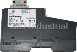
ALLEN-BRADLEY 1734-OA2

Description
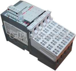
Allen Bradley 1734-OA2 Output Module - 120/230 V AC, 2 channel output module
Part Number
1734-OA2
Price
Request Quote
Manufacturer
ALLEN-BRADLEY
Lead Time
Request Quote
Category
I/O Module
Specifications
Delay Time, Off to On, Max
1/2 cycle
Delay Time, On to Off, Max
1/2 cycle
Dimensions (HxWxD), Approx.
56.0 x 12.0 x 75.5 mm (2.21 x 0.47 x 2.97 in.)
Enclosure Type Rating
None (open-style)
External ac Power Supply Voltage Range
85…264V dc, 27…63 Hz
External ac Power Supply Voltage, Nom
120/220V dc, 60 Hz
Isolation Voltage
240V, Reinforced Insulation Type Tested at 3250V dc for 60 s, field-side to system
Keyswitch Position
8
Module Location
1734-TB, 1734-TBS, 1734-TOP, or 1734-TOPS wiring base assembly
Mounting Type
DIN-rail
Nonoperating Shock
50 g
Nonoperating Temperature
-40…85 °C (-40…185 °F)
Off-state Leakage, Max
2.7 mA @ 264V ac
On-state Current, Max
750 mA per channel, 750 mA per output
On-state Current, Min
10 mA per channel
On-state Voltage Drop, Max
1.0V @ 0.75 A
On-state Voltage Range, Max
264V ac maximum
On-state Voltage Range, Min
74V ac
On-state Voltage Range, Nom
120/220V ac
Operating Shock
30 g
Operating Temperature
-20…55 °C (-4…131 °F)
Output Current Rating
1.5 A (2 channels @ 0.75 A each)
Outputs per Module
2 nonisolated, sourcing
Pilot Duty Rating
DC 14 Pilot Duty
POINTBus Current, Max
75 mA @ 5V dc
Power Dissipation, Max
2 W @ 264V ac
Product Temperature Versus Current Derating
1.5 A max per module @ 50 °C (122 °F), Derate linearly 13% to 1.3 A max per module @ 55 °C (131 °F)
Relative Humidity
5…95% noncondensing
Surge Current
16 A for 100 ms, repeatable every 10 s
Terminal Base Screw Torque
7 lb-in (0.8 Nm)
Thermal Dissipation, Max
6.8 BTU @ 264V ac
Vibration
5 g at 10…500 Hz
Weight, Approx
30.9 g (1.09 oz)
Wire Size
0.25... 2.5 mm2 (22...14 AWG) solid or stranded copper wire rated at 75 °C (167 °F ) or greater 1.2 mm (3/64 in.) insulation max
Wiring Category
1 - on signal ports(1)
Features
- A wide variety of voltage interface capabilities.
- Choice of direct-connect or rack-optimized communications.
- Field-side diagnostics on select modules.
- Isolated and non-isolated module types.
- Point-level output fault states for short-circuit and wire-off diagnostics.
Datasheet

Extracted Text
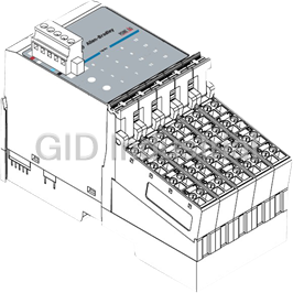
Installation Instructions POINT I/O 120/220V ac Output Module Catalog Numbers 1734-OA2, 1734-OA4, Series C Topic Page Important User Information 2 North American Hazardous Location Approval 3 Environment and Enclosure 4 Prevent Electrostatic Discharge 5 Before You Begin 6 Install the Mounting Base 8 Install the Module 9 Install the Removable Terminal Block (RTB) 11 Remove a Mounting Base 13 Wire the Module 14 Communicating with the Module 18 Interpret the LED Indicators 19 Specifications 21 Publication 1734-IN009D-EN-E - January 2007 2 POINT I/O 120/220V ac Output Module Important User Information Solid state equipment has operational characteristics differing from those of electromechanical equipment. Safety Guidelines for the Application, Installation and Maintenance of Solid State Controls (publication SGI-1.1 available from your local Rockwell Automation sales office or online at http://literature.rockwellautomation.com) describes some important differences between solid state equipment and hard-wired electromechanical devices. Because of this difference, and also because of the wide variety of uses for solid state equipment, all persons responsible for applying this equipment must satisfy themselves that each intended application of this equipment is acceptable. In no event will Rockwell Automation, Inc. be responsible or liable for indirect or consequential damages resulting from the use or application of this equipment. The examples and diagrams in this manual are included solely for illustrative purposes. Because of the many variables and requirements associated with any particular installation, Rockwell Automation, Inc. cannot assume responsibility or liability for actual use based on the examples and diagrams. No patent liability is assumed by Rockwell Automation, Inc. with respect to use of information, circuits, equipment, or software described in this manual. Reproduction of the contents of this manual, in whole or in part, without written permission of Rockwell Automation, Inc., is prohibited. Throughout this manual, when necessary, we use notes to make you aware of safety considerations. WARNING Identifies information about practices or circumstances that can cause an explosion in a hazardous environment, which may lead to personal injury or death, property damage, or economic loss. Identifies information that is critical for successful application and understanding of IMPORTANT the product. ATTENTION Identifies information about practices or circumstances that can lead to personal injury or death, property damage, or economic loss. Attentions help you to identify a hazard, avoid a hazard, and recognize the consequences. SHOCK HAZARD Labels may be on or inside the equipment, for example, a drive or motor, to alert people that dangerous voltage may be present. BURN HAZARD Labels may be on or inside the equipment, for example, a drive or motor, to alert people that surfaces may reach dangerous temperatures. Publication 1734-IN009D-EN-E - January 2007 POINT I/O 120/220V ac Output Module 3 North American Hazardous Location Approval The following information applies when Informations sur l’utilisation de cet équipement operating this equipment in hazardous en environnements dangereux. locations. Products marked CL I, DIV 2, GP A, B, C, D are suitable for Les produits marqués CL I, DIV 2, GP A, B, C, D ne conviennent use in Class I Division 2 Groups A, B, C, D, hazardous qu’à une utilisation en environnements de Classe I Division 2 locations and nonhazardous locations only. Each product is Groupes A, B, C, D dangereux et non dangereux. Chaque supplied with markings on the rating nameplate indicating produit est livré avec des marquages sur sa plaque the hazardous location temperature code. When d’identification qui indiquent le code de température pour les combining products within a system, the most adverse environnements dangereux. Lorsque plusieurs produits sont temperature code (lowest “T” number) may be used to combinés dans un système, le code de température le plus help determine the overall temperature code of the défavorable (code de température le plus faible) peut être system. Combinations of equipment in your system are utilisé pour déterminer le code de température global du subject to investigation by the local Authority Having système. Les combinaisons d’équipements dans le système Jurisdiction at the time of installation. sont sujettes à inspection par les autorités locales qualifiées au moment de l’installation. EXPLOSION HAZARD - RISQUE D’EXPLOSION – WARNING • Do not disconnect equipment unless • Couper le courant ou s’assurer que AVERTISSEMENT power has been removed or the area l’environnement est classé non is known to be nonhazardous. dangereux avant de débrancher • Do not disconnect connections to l'équipement. this equipment unless power has • Couper le courant ou s'assurer que been removed or the area is known l’environnement est classé non to be nonhazardous. Secure any dangereux avant de débrancher les external connections that mate to connecteurs. Fixer tous les this equipment by using screws, connecteurs externes reliés à cet sliding latches, threaded équipement à l'aide de vis, loquets connectors, or other means provided coulissants, connecteurs filetés ou with this product. autres moyens fournis avec ce • Substitution of components may produit. impair suitability for Class I, Division • La substitution de composants peut 2. rendre cet équipement inadapté à une • If this product contains batteries, utilisation en environnement de they must only be changed in an Classe 1, Division 2. area known to be nonhazardous. • S’assurer que l’environnement est classé non dangereux avant de changer les piles. This product is grounded through the DIN rail to chassis ground. Use ATTENTION zinc plated, yellow-chromate steel DIN rail to assure proper grounding. The use of other DIN rail materials, such as aluminum and plastic that can corrode, oxidize, or are poor conductors, can result in improper or intermittent grounding. Secure DIN rail to mounting surface approximately every 200 mm (7.87 in.) and use end-anchors appropriately. Publication 1734-IN009D-EN-E - January 2007 4 POINT I/O 120/220V ac Output Module Environment and Enclosure This equipment is intended for use in a Pollution Degree 2 industrial ATTENTION environment, in overvoltage Category II applications (as defined in IEC publication 60664-1), at altitudes up to 2000 meters (6562 feet) without derating. This equipment is considered Group 1, Class A industrial equipment according to IEC/CISPR Publication 11. Without appropriate precautions, there may be potential difficulties ensuring electromagnetic compatibility in other environments due to conducted as well as radiated disturbance. This equipment is supplied as open-type equipment. It must be mounted within an enclosure that is suitably designed for those specific environmental conditions that will be present and appropriately designed to prevent personal injury resulting from accessibility to live parts. The enclosure must have suitable flame-retardant properties to prevent or minimize the spread of flame, complying with a flame spread rating of 5VA, V2, V1, V0 (or equivalent) if non-metallic. The interior of the enclosure must be accessible only by the use of a tool. Subsequent sections of this publication may contain additional information regarding specific enclosure type ratings that are required to comply with certain product safety certifications. Besides this publication, see: • Industrial Automation Wiring and Grounding Guidelines, for additional installation requirements, Allen-Bradley publication 1770-4.1. • NEMA Standards publication 250 and IEC publication 60529, as applicable, for explanations of the degrees of protection provided by different types of enclosure. Publication 1734-IN009D-EN-E - January 2007 POINT I/O 120/220V ac Output Module 5 Prevent Electrostatic Discharge This equipment is sensitive to electrostatic discharge, which can ATTENTION cause internal damage and affect normal operation. Follow these guidelines when you handle this equipment: • Touch a grounded object to discharge potential static. • Wear an approved grounding wriststrap. • Do not touch connectors or pins on component boards. • Do not touch circuit components inside the equipment. • Use a static-safe workstation, if available. • Store the equipment in appropriate static-safe packaging when not in use. Publication 1734-IN009D-EN-E - January 2007 6 POINT I/O 120/220V ac Output Module Before You Begin Note that this series C product can be used with the following: • DeviceNet and PROFIBUS adapters • ControlNet and EtherNet/IP adapters, using RSLogix 5000 software, version 11 or later See the figures to familiarize yourself with major parts of the module, noting that the wiring base assembly consists of one of the following: • 1734-TB or 1734-TBS POINT I/O two-piece terminal base, which includes the 1734-RTB removable terminal block • 1734-TOP or 1734-TOPS one-piece terminal base Module Locking Slide-in Writable Label Mechanism Module Insertable Wiring I/O Module Diagram DIN Rail Locking Screw (orange) Removable Terminal Block Handle Mechanical Removable Keying (orange) Terminal Block with Screw or Interlocking Spring Side Pieces Clamp 1734-TB or 1734-TBS 4182OA Mounting Base Publication 1734-IN009D-EN-E - January 2007 Module Status Network Status NODE: 120/220VAC Output 0 1 POINT I/O 120/220V ac Output Module 7 Module Locking Slide-in Writable Label Mechanism Insertable Module Wiring Diagram I/O Module DIN Rail Locking Screw (orange) Handle 1734-TOP or 1734-TOPS Mechanical One-piece Keying (orange) Terminal Base with Screw or Interlocking Spring Side Pieces Clamp 44221 Publication 1734-IN009D-EN-E - January 2007 8 POINT I/O 120/220V ac Output Module Install the Mounting Base To install the mounting base on the DIN rail, proceed as follows. 1. Position the mounting base vertically above the installed units (adapter, power supply, or existing module). Slide the mounting base until the interlocking side pieces engage the adjacent module or adapter. 31586 2. Slide the mounting base down so that the interlocking side pieces engage the adjacent module or adapter. 3. Press firmly to seat the mounting base on the DIN rail so that the mounting base snaps into place. Publication 1734-IN009D-EN-E - January 2007 POINT I/O 120/220V ac Output Module 9 Install the Module The module can be installed before or after base installation. Make sure that the mounting base is correctly keyed before installing the module into the mounting base. In addition, make sure the mounting base locking screw is positioned horizontally with reference to the base Turn the keyswitch to align the number with the notch. 1734-TB base is shown. Notch position 3 is shown. Be sure the DIN-rail locking screw is in the horizontal position. 44229 Publication 1734-IN009D-EN-E - January 2007 10 POINT I/O 120/220V ac Output Module Be sure the DIN-rail locking screw is in the 1734-TOP base is shown. horizontal position. Turn the keyswitch to align the number with the notch. Notch position 1 is shown. 44228 Publication 1734-IN009D-EN-E - January 2007 POINT I/O 120/220V ac Output Module 11 . When you insert or remove the module while backplane power is on, WARNING an electrical arc can occur. This could cause an explosion in hazardous location installations. Be sure that power is removed or the area is nonhazardous before proceeding. Repeated electrical arcing causes excessive wear to contacts on both the module and its mating connector. Worn contacts may create electrical resistance that can affect module operation. 1. Using a bladed screwdriver, rotate the keyswitch on the mounting base clockwise until the number required for the type of module being installed aligns with the notch in the base. 2. Make certain the DIN-rail locking screw is in the horizontal position, noting that you cannot insert the module if the locking mechanism is unlocked. Install the Removable Terminal Block (RTB) A removable terminal block (RTB) is supplied with your wiring base assembly. To remove, pull up on the RTB handle,. You can remove and replace the mounting base as necessary without removing any of the wiring. To reinsert the removable terminal block, proceed as follows. 1. Insert the end opposite the handle into the base unit, noting that this end has a curved section that engages with the wiring base. 2. Rotate the terminal block into the wiring base until it locks itself in place. Publication 1734-IN009D-EN-E - January 2007 12 POINT I/O 120/220V ac Output Module 3. If an I/O module is installed, snap the RTB handle into place on the module. Insert the module straight down into the mounting base. Hook the RTB end into the mounting base end and rotate until it locks into place. 44011 When you connect or disconnect the removable terminal block (RTB) WARNING with field-side power applied, an electrical arc can occur. This can cause an explosion in hazardous location installations. Be sure that power is removed or the area is nonhazardous before proceeding. Publication 1734-IN009D-EN-E - January 2007 POINT I/O 120/220V ac Output Module 13 Remove a Mounting Base To remove a mounting base, you must remove any installed module and the module installed in the base to the right. Remove the removable terminal block (RTB), if wired. 1. Unlatch the RTB handle on the I/O module. 2. Pull on the RTB handle to remove the RTB. When you connect or disconnect the removable terminal block (RTB) WARNING with field-side power applied, an electrical arc can occur. This can cause an explosion in hazardous location installations. Be sure that power is removed or the area is nonhazardous before proceeding 3. Press on the module lock on the top of the module 4. Pull on the I/O module to remove it from the base. When you insert or remove the module while backplane power is on, WARNING an electrical arc can occur. This could cause an explosion in hazardous location installations. Be sure that power is removed or the area is nonhazardous before proceeding. Repeated electrical arcing causes excessive wear to contacts on both the module and its mating connector. Worn contacts may create electrical resistance that can affect module operation. Publication 1734-IN009D-EN-E - January 2007 14 POINT I/O 120/220V ac Output Module 5. Repeat steps 1…4 for the module to the right. 6. Use a small-bladed screwdriver to rotate the orange base-locking screw to a vertical position to release the locking mechanism. 7. Lift straight up to remove. Wire the Module To wire the module, refer to the figures and tables. If you connect or disconnect wiring while the field-side power is on, WARNING an electrical arc can occur. This could cause an explosion in hazardous location installations. Be sure that power is removed or the area is nonhazardous before proceeding. Publication 1734-IN009D-EN-E - January 2007 POINT I/O 120/220V ac Output Module 15 Wiring the Module 1734-OA2 Module 1734-OA4 Module Status Module Status Status Module Status Network Status Network Network Status Network Status Status NODE: NODE: NODE: 120VAC Input 120/220VAC Output Status of Output 0 Status of Output 0 0 0 1 Status of Output 1 1 Status of Output 1 2 Status of Output 2 3 1734 Status of Output 3 OA2 1734 OA4 Channel 1 Channel 0 Channel 1 Channel 0 Connection Connection Connection Connection No Connection No Connection Channel 3 Channel 2 Connection Connection L2/N L2/N L2/N L2/N L1 L1 L2/N = 120/220V ac return L2/N L2/N L1 = 120/220V ac Supply 42016-OA 42016-OA4 Publication 1734-IN009D-EN-E - January 2007 16 POINT I/O 120/220V ac Output Module Catalog Number 1734-OA2 0 1 Ch 0 Ch 1 2 3 NC NC Load Load 4 5 L1 =120/220V ac Supply L2/N L2/N L2/N = 120/220V ac Return 6 7 Ch 0 = Channel 0 L1 L1 Ch 1 = Channel 1 42014 Field power is supplied from internal power bus. Channel Output Terminal Common Terminal Power 00 4 6 11 5 7 Module power is supplied from the internal power bus. Publication 1734-IN009D-EN-E - January 2007 POINT I/O 120/220V ac Output Module 17 Catalog Number 1734-OA4 0 1 Ch0 Ch1 2 3 Ch2 Ch3 Load Load Load Load 4 5 L2/N L2/N 6 7 L2/N L2/N L1 =120/220V ac Supply 42015 L2/N = 120/220V ac Return Ch 0 = Channel 0 Ch 2 = Channel 2 Ch 1 = Channel 1 Ch 3 = Channel 3 Field power is supplied from the internal power bus. Channel Output Terminal Common Terminal Power 00 4 11 5 22 6 33 7 Publication 1734-IN009D-EN-E - January 2007 18 POINT I/O 120/220V ac Output Module Communicating with the Module I/O messages are sent to (consumed) and received from (produced) the POINT I/O modules. These messages are mapped into the processor’s memory. This POINT I/O output module consumes 1 byte of output data (scanner Tx). It does not produce data (scanner Rx). Refer to the table that shows the default data map. Default Data Map for 1734-OA2 Modules 765 43 2 1 0 Produces No produced data (scanner Rx) Consumes Not used Ch1 Ch0 Channel state (scanner Tx) Where: 0 = Off, 1 = On Default Data Map for 1734-OA4 Modules 76543 2 1 0 Produces No produced data (scanner Rx) Consumes Not used Ch 3 Ch 2 Ch1 Ch0 Channel state (scanner Tx) Where: 0 = Off, 1 = On Publication 1734-IN009D-EN-E - January 2007 POINT I/O 120/220V ac Output Module 19 Interpret the LED Indicators See the figures and tables for information about how to interpret LED indicators. Module Status Module Status Network Status Network Status Status of Output 0 Status of Output 0 Status of Output 1 Status of Output 1 Status of Output 2 Status of Output 3 44209 44210 Interpret the LED Indicators State Description Recommended Action Module Status Off No power applied to device. Apply power to device. Green Device operating normally. None. Flashing Green Device needs commissioning due to Configure device properly. configuration missing, incomplete, or incorrect. Flashing Red Recoverable fault. 1. Cycle power to device. 2. If condition persists, replace device. Red Unrecoverable fault may require Replace device. device replacement. Publication 1734-IN009D-EN-E - January 2007 20 POINT I/O 120/220V ac Output Module Interpret the LED Indicators State Description Recommended Action Flashing Device is in self-test. None. Red/Green Network Status Off Device is not online. Apply power to device, wait - Device has not completed for MAC_id to complete, and dup_MAC_id test. correct, as needed. - Device not powered - check module status indicator. Flashing Green Device is online but has no None - device is in Idle or connections in the established state. Program mode. Green Device online and has connections in None. the established state. Flashing Red One or more I/O connections in Check for I/O module failure, timed-out state. and correct, as needed. Red Critical link failure - failed Verify that adapter and communication device. Device terminal bases are properly detected error that prevents it installed, and reinstall, as communicating on the network. needed. Flashing Communication faulted device - the Verify that adapter is properly Red/Green device has detected a network access installed, and reinstall, as error and is in communication faulted needed. state. Device has received and accepted an Identify Communication Faulted Request - long protocol message. I/O Status Off All outputs inactive. None. Yellow One or more outputs are active and None. under control. Publication 1734-IN009D-EN-E - January 2007 POINT I/O 120/220V ac Output Module 21 Specifications 120/220V ac Output Modules - 1734-OA2 and 1734-OA4 Attribute Value Outputs per Module 2 nonisolated, sourcing - 1734-OA2 4 nonisolated, sourcing - 1734-OA4 On-state Voltage Range, Min 74V ac On-state Voltage Range, Nom 120/220V ac On-state Voltage Range, Max 264V ac maximum On-state Voltage Drop, Max 1.0V @ 0.75 A On-state Current, Min 10 mA per channel On-state Current, Max 750 mA per channel For 1734-OA4 - 750 mA per output, 2.0 A max per module Off-state Leakage, Max 2.7 mA @ 264V ac Output Current Rating 1.5 A (2 channels @ 0.75 A each) - 1734-OA2 2.0 A (750 mA per output, 2.0 A max per module - 1734-OA4 Product Temperature Versus 1734-OA2: 1.5 A max per module @ 50 °C (122 °F) Current Derating Derate linearly 13% to 1.3 A max per module @ 55 °C (131 °F) 1734-OA4: 2.0 A max per module @ 45°C (113 °F) Derate linearly 30% to 1.4 A max per module @ 55 °C (131 °F) Surge Current 16 A for 100 ms, repeatable every 10 s (1) 1/2 cycle Delay Time, Off to On, Max Delay Time, On to Off, Max 1/2 cycle Keyswitch Position 8 (1) Off/on delay is time from a valid output on signal to output energization. On/off delay is time from a valid output off signal to output deenergization. Publication 1734-IN009D-EN-E - January 2007 22 POINT I/O 120/220V ac Output Module General Attribute Value Module Location 1734-TB, 1734-TBS, 1734-TOP, or 1734-TOPS wiring base assembly POINTBus Current, Max 75 mA @ 5V dc Power Dissipation, Max 2 W @ 264V ac - 1734-OA2 3.5 W @ 264V ac - 1734-OA4 Thermal Dissipation, Max 6.8 BTU @ 264V ac - 1734-OA2 11.9 BTU @ 264V ac - 1734-OA4 Isolation Voltage 240V, Reinforced Insulation Type Tested at 3250V dc for 60 s, field-side to system External ac Power Supply 120/220V dc, 60 Hz Voltage, Nom External ac Power Supply 85…264V dc, 27…63 Hz Voltage Range Dimensions (HxWxD), 56.0 x 12.0 x 75.5 mm (2.21 x 0.47 x 2.97 in.) Approx. (1) Wiring Category 1 - on signal ports 2 Wire Size 0.25... 2.5 mm (22...14 AWG) solid or stranded copper wire rated at 75 °C (167 °F ) or greater 1.2 mm (3/64 in.) insulation max Weight, Approx 30.9 g (1.09 oz) Enclosure Type Rating None (open-style) Terminal Base Screw Torque 7 lb-in (0.8 Nm) Pilot Duty Rating DC 14 Pilot Duty (1) Use this conductor category information for planning conductor routing as described in Industrial Automation Wiring and Grounding Guidelines, publication 1770-4.1 . Publication 1734-IN009D-EN-E - January 2007 POINT I/O 120/220V ac Output Module 23 Environmental Specifications Attribute Value Temperature, Operating IEC 60068-2-1 (Test Ad, Operating Cold), IEC 60068-2-2 (Test Bd, Operating Dry Heat), IEC 60068-2-14 (Test Nb, Operating Thermal Shock): -20…55 °C (-4…131 °F) Temperature, Storage IEC 60068-2-1 (Test Ab, Unpackaged Nonoperating Cold), IEC 60068-2-2 (Test Bb, Unpackaged Nonoperating Dry Heat), IEC 60068-2-14 (Test Na, Unpackaged Nonoperating Thermal Shock): -40…85 °C (-40…185 °F) North American Temp T4 Code Relative Humidity IEC 60068-2-30 (Test Db, Unpackaged Damp Heat): 5…95% noncondensing Vibration IEC 60068-2-6 (Test Fc, Operating): 5 g at 10…500 Hz Shock, Operating IEC 60068-2-27 (Test Ea, Unpackaged Shock): 30 g Shock, Nonoperating IEC 60068-2-27 (Test Ea, Unpackaged Shock): 50 g Vibration IEC 60068-2-6 (Test Fc, operating) tested 5 g @ 10…500 Hz ESD Immunity IEC 61000-4-2: 6 kV contact discharges 8 kV air discharges Radiated RF Immunity IEC 61000-4-3: 10V/m with 1 kHz sine-wave 80%AM from 80…2000 MHz 10V/m with 200 Hz 50% Pulse 100%AM at 900 MHz 10V/m with 200 Hz 50% Pulse 100%AM at 1890 MHz 3V/m with 1 kHz sine-wave 80%AM from 2000…2700 MHz Conducted RF Immunity IEC 61000-4-6: 10V rms with 1 kHz sine-wave 80%AM from 150 kHz…80 MHz Publication 1734-IN009D-EN-E - January 2007 Environmental Specifications Attribute Value EFT/B Immunity IEC 61000-4-4: ±4 kV at 5 kHz on signal ports Surge Transient IEC 61000-4-5: Immunity ±1 kV line-line (DM) and ±2 kV line-earth (CM) on signal ports Emissions CISPR 11 Group 1, Class A Certifications Certification Value c-UL-us UL Listed Industrial Control Equipment, certified for US and Certifications Canada. See UL File E65584. (when UL Listed for Class I, Division 2 Group A,B,C,D Hazardous product is Locations, certified for U.S. and Canada. See UL File (1) marked) E194810. CE European Union 89/336/EEC EMC Directive, compliant with: EN 50082-2; Industrial Immunity EN 61326; Meas./Control/Lab., Industrial Requirements EN 61000-6-2; Industrial Immunity EN 61000-6-4; Industrial Emissions EN 61131-2; Programmable Controllers (Clause 8, Zone A and B) European Union 2006/95/EC LVD, compliant with: EN 61131-2; Programmable Controllers (Clause 11) C-Tick Australian Radiocommunications Act, compliant with: AS/NZS CISPR 11; Industrial Emissions (1) See the Product Certification link at http://www.ab.com for Declarations of Conformity, Certificates, and other certification details. Allen-Bradley, POINT, POINTBus, and RSLogix 5000 are trademarks of Rockwell Automation, Inc. Trademarks not belonging to Rockwell Automation are property of their respective companies. Publication 1734-IN009D-EN-E - January 2007 PN 953030-58 Supersedes publication 1734-IN009C-EN-P - April 2002 Copyright © 2007 Rockwell Automation, Inc. All rights reserved. Printed in the U.S.A.
Frequently asked questions
How does Industrial Trading differ from its competitors?

Is there a warranty for the 1734-OA2?
Which carrier will Industrial Trading use to ship my parts?
Can I buy parts from Industrial Trading if I am outside the USA?
Which payment methods does Industrial Trading accept?
Why buy from GID?

Quality
We are industry veterans who take pride in our work

Protection
Avoid the dangers of risky trading in the gray market

Access
Our network of suppliers is ready and at your disposal

Savings
Maintain legacy systems to prevent costly downtime

Speed
Time is of the essence, and we are respectful of yours
Related Products
Rockwell Automation 1734-232ASC Serial I/O Modules- Inputs/Outputs 1 Serial Interface channel, Point...
Rockwell Automation 1734-485ASC Serial I/O Modules- Inputs/Outputs 1 Serial Interface channel, Point...
Allen Bradley 1734-ADN I/O Adapter Module - 24V DC DeviceNet Adapter
Allen Bradley 1734-ADNX Adapter Module - DeviceNet I/O Adapter with Expansion Port, 63 POINT I/O mod...
Allen Bradley 1734d-IA16 PointBlock I/O Module - 120 VAC, 16 Inputs, DNET communication interface
Allen Bradley 1734d-IA16S PointBlock I/O Module - 120 VAC, 16 Inputs, DNET communication interface, ...
Request a Quote

The quote request has been received
Close

Facing challenges or have inquiries? Feel free to contact us!
Call Us +1-469-283-2440
What they say about us
FANTASTIC RESOURCE
One of our top priorities is maintaining our business with precision, and we are constantly looking for affiliates that can help us achieve our goal. With the aid of GID Industrial, our obsolete product management has never been more efficient. They have been a great resource to our company, and have quickly become a go-to supplier on our list!
Bucher Emhart Glass
EXCELLENT SERVICE
With our strict fundamentals and high expectations, we were surprised when we came across GID Industrial and their competitive pricing. When we approached them with our issue, they were incredibly confident in being able to provide us with a seamless solution at the best price for us. GID Industrial quickly understood our needs and provided us with excellent service, as well as fully tested product to ensure what we received would be the right fit for our company.
Fuji
HARD TO FIND A BETTER PROVIDER
Our company provides services to aid in the manufacture of technological products, such as semiconductors and flat panel displays, and often searching for distributors of obsolete product we require can waste time and money. Finding GID Industrial proved to be a great asset to our company, with cost effective solutions and superior knowledge on all of their materials, it’d be hard to find a better provider of obsolete or hard to find products.
Applied Materials
CONSISTENTLY DELIVERS QUALITY SOLUTIONS
Over the years, the equipment used in our company becomes discontinued, but they’re still of great use to us and our customers. Once these products are no longer available through the manufacturer, finding a reliable, quick supplier is a necessity, and luckily for us, GID Industrial has provided the most trustworthy, quality solutions to our obsolete component needs.
Nidec Vamco
TERRIFIC RESOURCE
This company has been a terrific help to us (I work for Trican Well Service) in sourcing the Micron Ram Memory we needed for our Siemens computers. Great service! And great pricing! I know when the product is shipping and when it will arrive, all the way through the ordering process.
Trican Well Service
GO TO SOURCE
When I can't find an obsolete part, I first call GID and they'll come up with my parts every time. Great customer service and follow up as well. Scott emails me from time to time to touch base and see if we're having trouble finding something.....which is often with our 25 yr old equipment.
ConAgra Foods