

 Manufacturers
WARNER ELECTRIC SE2102

Description
WARNER ELECTRIC-SE2102-DC DRIVE 2HP115/230VAC 90/180VDC 10ADC
Part Number
SE2102
Price
Request Quote
Manufacturer
WARNER ELECTRIC
Lead Time
Request Quote
Category
None
Specifications
115 VAC
1/4–1 HP
Supply
230 VAC
1/2–5 HP in two models
AC Line
Frequency
Input
Acceleration
0.3 to 30 seconds
Altitude
To 3300 ft. (1000m)
Armature Voltage
±2%
Chassis Model
55°C
Current Range
(Torque) 15–150%
Deceleration
0.3 to 30 seconds
Duty
Continuous
Enclosed Model
40°C
IR Compensation
Improves load regulation in
Line Protection
Circuit Breaker (except Power
Max. Load Capacity
150% for 1 min.
Maximum Speed
70–105% of motor base speed
Minimum Speed
0–30% of motor base speed
Preset Jog
0–100% of motor base speed
Relative Humidity
95% non condensing
Service Factor
1.0
Speed Reference Signal Voltage
0–10 VDC
Speed Regulation
(As % of motor
Tachometer Feedback
±0.5% (depending on tach
Torque Slope
Increasing torque to decreasing
Features
- designed to control shunt wound
- motors from 1/4 to 5 HP.
- Non-regenerative, DC drives are
- or permanent magnet field DC
- SE2000 series
Datasheet

Extracted Text
SUPPORTED BY DANA CORPORATION WARNER ELECTRIC The Warner Electric Motors and Controls Division of Dana Corporation is a global leader in the engineer- ing and manufacturing of motor and control products for industrial applications. All Warner Electric products and services are backed by highly specialized engineers and service people who can help solve your production challenges. Warner Electric’s capabilities and products have improved operations for hundreds of companies around the world. ® Warner Electric stepper motors and controls, servo motors and controls, voltage conditioning products, engineered systems, and AC/DC drives are available worldwide through an extensive authorized distribu- SE 2000 tor network. These distributors provide convenient service by offering technical support, replacement DC Drives parts, and literature, as well as an extensive inventory of off-the-shelf models for the fastest possible delivery and service. Call your nearest distributor for ordering and application information. IN U.S.A. AND CANADA WARNER ELECTRIC MOTORS AND CONTROLS DIVISION Sales: 734-669-4700 Customer Service: 800-787-3532 Product Application: 800-787-3532 Product Literature Request: 800-787-3532 Fax: 800-766-6366 or 860-589-2136 Web Site: www.warnernet.com SERVO CONTROLS STEPPER CONTROLS VOLTAGE CONDITIONING ENGINEERED SYSTEMS AC/DC DRIVES WARNER ELECTRIC MOTORS AND CONTROLS DIVISION Division Office Bristol Plant Systems Center International - Europe 640 Avis Drive, Suite 200 383 Middle Street 13500-J South Point Blvd. Lausanne, Switzerland Ann Arbor, MI 48108 Bristol, CT 06010 Charlotte, NC 28273 La Pierreire CH-1029 Villars-Ste-Croix, Switzerland ©1999 Warner Electric Division C3005 9/99 Printed in U.S.A. SE2000 Coverall 1 3/25/05, 1.32 ADDITIONAL WARNER ELECTRIC DC DRIVES & CONTROLS A Total Commitment Through Distribution • Throughout the North American Conti- • An extention of the commitment to product nent distributors provide one stop product service is carried to each and every customer availability and expertise through the dedicated distributor network. • A carefully oriented plan is made with each • Each Distributor is a Market specialist to meet local and immediate needs. distrubutor to insure optimum coverage and service for each market area. ® BRONCO II and Washdown Series DC Drives QUADRALINE 7000 DC Drives • Literally thousands of sales and service ® Designed for full wave, regenerative applications, the Designed for tough rugged applications, BRONCO II DC personnel form the total team commitment for Quadraline 7000 is designed for either permanent magnet Drives feature speed regulation ± 0.5 – 1%, dual voltage product and sales assurance. or wound feild DC motors from ¼ to 5 HP. It features input (115/230 VAC), output 90 or 180 VDC, ¼ to 2 HP, fullwave 4-quadrant operation, seven selectable perfor- circuit protection, torque control, local or remote operator mance features, electronic reversing and seven control control, open chassis, field programmable jumpers, adjustments, positioning accuracy. Chassis or NEMA 4/12 control relay with 3-wire start/stop circuit, jog at enclosures available and UL listed. potentiometer speed, cast aluminium enclosure – NEMA 4, NEMA 12, and NEMA 4X. Maximum and minimum speed adjustments. M4000 Digital 3-Phase DC Drives DS9000 Digital Drive Speed Controller The M4000 Series Digital 3-Phase DC Drive is a The DS9000 Digital Speed Controller features long term programmable, microprocessor based variable speed DC speed accuracy, control and stability. It offers 16-bit drive. It allows keypad control of each parameter. Digital microprocessor based, AC or DC drive control, ± .01% YOUR DISTRIBUTOR IS: readout provides on-line monitoring of drive operation. accuracy, digital master or follower, analog or digital Ideal for many drive applications including wire and input, and two selectable sets of programmable param- cable, packaging/converting, machinery and material eters. Front panel controls include a 4-digit LED readout, handling. Improved circuit board technology has added keypad controls and four LED status indicators. standard features, including serial communications and a field-weakening controller for constant power and extended speed range applications. *Contact Warner Electric for information on our complete line of AC Drives. SE2000 Coverall 2 3/25/05, 1.34 SE 2000 SE 2000 Contents Contents Features and Benefits . . . . . . . 2 Applications . . . . . . . . . . . . . . . 4 Specifications . . . . . . . . . . . . . 5 How to Order . . . . . . . . . . . . . . 6 Selection Information . . . . . . . 7 Options— Enhanced Process Follower . . . . . . . . . . . . . . . . 8 Digital Signal Follower . . . . . 9 Controlled Decel Stop . . . . 10 Fault Module . . . . . . . . . . . 11 Remote Operator Stations . . . . . . . . . . . . . . . . . 12 Isolation Transformers . . . . . 12 Standard DC Motors . . . . . . . 13 Dimensions . . . . . . . . . . . . . . 16 Connection Diagrams . . . . . . 17 Adjustment Locations . . . . . . 18 Recommended Spare Parts . . . . . . . . . . . . . . . . . . . 19 Service . . . . . . . . . . . . . . . . . 19 SE 2000 SE 2000 20 1 SE200Spreads 1 3/25/05, 1.26 SE 2000 SE 2000 Recommended Spare Parts Standard Features Recommended Features and Warner Electric SE2000 series Circuit protection Torque and Slope Control Spare Parts Benefits Part Number Non-regenerative, DC drives are Transient voltage protection by Precise setting of motor torque Description 1/4-2 HP Models 3-5 HP Models designed to control shunt wound MOV. All models except Power and slope control to give Control Board Assembly* SPC36269 SPC36269 or permanent magnet field DC Unit have AC circuit breaker for increasing torque/decreasing motors from 1/4 to 5 HP. line protection. speed characteristic above fixed torque limit for simple center SCR Module ATY4001-03 ATY4008-00 Isolation Chassis unit winder applications. Isolated 4–20mA or 0–10 VDC Dead front and back construction. Control relay with three wire Circuit Breaker Chassis control signal. Control circuit is Hinged cover provides easy Start/Stop circuit. All models have ASW4045-00 isolated from main circuit access to all components. control relay to prevent automatic (Single Pole) ASW4051-00 potential for improved safety and restart after power outage for Jog Enclosed (Double Pole) use in multi-motor systems. increased safety (may be ASW4045-01 (All Models) Jog at separately adjustable reconnected for line start Tachometer generator (Double Pole) speed. operation if required). feedback Diagnostic Status Motor Contactor Card SPB36401-00 SPB36429-00 For improved speed regulation, Field Supply with Field Loss • Power on LED unit will accept feedback from an Circuit. analog tach generator or digital Reversing Contactor Card SPB36401-01 SPB36429-01 • Trip LED Overcurrent Protection pulse tach generator or magnetic • Torque Limit LED pickup. Timed overcurrent trip circuit for Motor Contactor(s) On card ARE3001-05 • Run LED motor protection. Full wave power conversion • Field Loss LED circuit with two SCR’s and AC Supply Frequency Dynamic Braking Resistor PRE2025-01 PRE2025-00 three diodes providing NEMA 224714-001 224714-100 • Allows drive to be operated on Code K, DC armature supply 50 Hz or 60 Hz supply. Product Type Code insures optimum motor • Enclosed models meet NEMA Power On Lamp ALI1025-00 ALI1025-00 performance, cooler motor Power Unit 4/12 specifications. � 226723-000 226723-000 operation and longer life. Basic On-Off RUN-BRAKE Listed Clear Lamp Lens ALI1024-00 ALI1024-00 REV-BRAKE � 226722-000 Enclosed Listed for use in Canada *Note Lamp Holder ALI1028-00 ALI1028-00 � 226647-000 When replacing the control board assembly, it is essential that all of the set-up jumpers on the new Rubber Boot Kit HMI1026-03 HMI1026-03 board are identical with those on � 226579-003 the board being replaced. It may also be necessary to adjust the Water Tight Nut HMI1012-00 HMI1012-00 potentiometers on the new board � 224638-000 for corret operation. Potentiometer Knob HKN1001-00 HKN1001-00 � 224539-000 Service Toggle Switch Boot HMI1103-00 HMI1103-00 � 224639-000 Service It is intended that the SE 2000 should be serviced by replacing major sub-assemblies. The Replacement Parts List lists all of the sub- assemblies required to service SE 2000 drives. It is recommended that users keep these parts readily available to support the drive’s critical applications. For additional assistance or the name of your closest authorized service center, contact Warner Electric Motors and Controls SE 2000 SE 2000 customer service at 800-787-3532. 2 19 SE200Spreads 2 3/25/05, 1.26 SE 2000 SE 2000 Selectable Programming Adjustments Jumper and Features and Jumper selectable to program Customer adjustments match Adjustment Benefits drives for specific motor or control to application. 1 2 3 4 application: Locations Maximum Speed Voltage Jumper Limits speed available to operator Selects 115 or 230 VAC supply 123 4 5 678 9 10 11 12 13 14 15 16 17 18 12 25 Armature voltage 90 or 180 VDC Minimum Speed P 11 24 Minimum motor speed Current Scaling P11-24 Selects 5 current ranges of motor J4 IR Compensation HP A B C R98 Improves motor speed regulation Jumper Location Acceleration/Deceleration in armature feedback mode TRQ on Power Unit Time 1 14 SW1 and Basic On/Off Acceleration R99 Models SPD Selects range of adjustment J5 Sets time to reach full speed control to 30 seconds (Factory Field Adjust R32 Loss Torque or Speed Control R100 Deceleration Only) Selects mode of either motor Sets time to decelerate to zero Run speed or motor torque controlled speed A B R101 by operator’s potentiometer J6 C Torque D Overcurrent Trip E Run—Brake Sets motor torque available A PC ASSY Timed, instantaneous or disabled (current limit) B J7 C • 1.0 seconds Slope • 60 seconds Power R107 • No trip Produces increasing torque as On speed decreases Overcurrent Field Loss Protection Trip J1 Torque Jog For shunt wound motors Limit 90 180 Sets separate jog speed J8 Internal/External Pre-Set Jog Allows jog speed to be set R112 internally or externally 115V 115V A 230V B Motor Speed Regulating J2 J3 J9 C D Feedback E • By armature voltage; ± 2% TB1 R116 speed regulation • By 7 VDC/1000RPM analog tachometer; ± 0.5% speed R117 regulation • By 50 VDC/1000RPM analog F2 F1 A2 A1 L2 L1 tachometer; ± 0.5% speed regulation • By 60 PPR digital tachometer, AC ± 0.5% speed reguation Line Input • By 120 PPR digital tachometer, ± 0.5% speed regulation A1 DC Motor Armature A2 F1 F2 DC Motor Field SE 2000 SE 2000 18 3 SE200Spreads 3 3/25/05, 1.26 Remote Operator Jog Run Jog Run Start Stop Zero Speed Pot Jog ACCEL SLOPE TORQUE MAX SPD IR COMP MIN SPD DECEL CW (+10V) 0 CCW Jog Reference Process Follower Output Circuit Common Process Follower Input Circuit Common Tachometer Start/Stop Stop NC Start/Stop Start Reverse Forward SE 2000 SE 2000 Winders SE2000 Connection Applications • Torque control Basic On-Off or Run Brake Models Reversing Brake Models Diagrams • Smooth, adjustable Field (-) acceleration rate F2 Field (-) 1 Forward 1 Forward F2 Forward Reverse 2 2 Reverse • Slope Adjustment Field (+) F1 Field (+) F1 Start 3 3 Start • Provides constant tension Jog Jog Armature A2 Start Start Armature A2 Start/Stop Start/Stop 4 4 Run Run Armature A1 Armature A1 5 NC NC Stop 5 Stop 6 Stop 6 Stop L1 Motor Line Voltage L1 Motor Line Voltage Thermostat 115 or 230 VAC Thermostat 115 or 230 VAC 7 7 50/60 Hz L2 50/60 Hz L2 Auxiliary contacts for Auxiliary contacts for 8 Start/Stop 8 Start/Stop Start Indication Start Indication 9 9 Optional Optional Motor Tachometer TB1 10 Tachometer Motor Tachometer Tachometer TB1 10 or Magnetic Pickup or Magnetic Pickup (See Note 1) 11 Circuit Common Circuit Common (See Note 1) 11 Process Follower Input Process Signal 12 12 Process Follower Input Process Signal 0-10V or 4–20 mA 0-10V or 4–20 mA Circuit Common 13 13 Circuit Common (See Note 2 for Polarity) (See Note 2 for Polarity) Conveyors 14 Process Follower Output 14 Process Follower Output 15 Jog Reference Jog Reference 15 • Controlled stops and rapid CCW 16 CCW 16 braking Jog Auto Note 1: Circuit accepts either Jog Auto Wiper 2K 17 2K 17 Wiper polarity of tach voltage. • Bi-directional control Speed Speed Note 2: Terminal 12 positive for Man Man 18 CW (+ 10V) run 18 CW (+ 10V) Pot run Pot 0-10 volt input. Terminal 12 negative • Remote control when 4-20 mA input is used. TB2 TB2 Note 1: Circuit accepts either polarity of tach voltage. Note 2: Terminal 12 positive for Three Wire Start/Stop with Reversing, 0-10 volt input. Terminal 12 negative Tachometer, Run/Jog, Auto/Man and when 4-20 mA input is used. Motor Thermostat. Shunt Field Printing Presses Connections • Dynamic braking L1 L1 Line input DC MOTOR DC MOTOR Line input • Controlled adjustable CONTROLLER 115 VAC 115 VAC CONTROLLER L2 L2 acceleration and deceleration • Automatic or manual speed A1 DC motor A1 DC motor control. armature armature A2 90 VDC A2 90 VDC F1 F1 DC motor DC motor shunt field F2 shunt field F2 100 VDC 50 VDC Connections for a DC motor with a Connections for a DC motor with a 90 VDC armature and 100 VDC 90 VDC armature and 50% VDC shunt field. shunt field. Stretch Wrap Machines L1 L1 DC MOTOR Line input DC MOTOR Line input 230 VAC 230 VAC CONTROLLER CONTROLLER • Torque control L2 L2 • Speed control A1 DC motor A1 DC motor • Local or remote operation armature armature A2 A2 180 VDC 180 VDC F1 F1 DC motor DC motor shunt field F2 F2 shunt field 200 VDC 100 VDC Connections for a DC motor with a Connections for a DC motor with a 180 VDC armature and 200 VDC 180 VDC armature and 100 VDC SE 2000 SE 2000 shunt field. shunt field. 4 17 SE200Spreads 4 3/25/05, 1.26 SE 2000 SE 2000 Models Performance Characteristics Dimensions Power Unit Specifications Speed Range 30:1 (arm fdbk) Power Unit 1/2–2 HP Models 3–5 HP Models 50:1 (tach fdbk) .218 Dia. (4) .218 Dia. (4) Consists of control board, SCR Speed Regulation (As % of motor power bridge, and terminals. base speed) for 95% load change Armature Voltage ± 2% Basic On-Off Tachometer Feedback ± 0.5% (depending on tach 6.0 Power Unit with single pole AC 6.0 generator) 6.878 line circuit breaker. Two pole 6.5 Acceleration/Deceleration breaker is standard on all 3–5 HP Range A By current limit models and all enclosed models. Range B 3–30 seconds Range C 0.3–3 seconds Run-Brake Model Depth 3.86 Depth 4.822 5.937 8.5 7.625 Models include motor contactor 9.0 Operating Conditions and dynamic braking. Ambient Temperature Reversing-Brake Chassis Model 55°C Models include forward and SE2005 Enclosed Model 40°C reversing contactors with anti- Relative Humidity 95% non condensing plugging and dynamic braking. Chassis Altitude To 3300 ft. (1000m) Adjustments Basic On-Off or Run Brake Models Options Reversing Brake Models Current Range (Torque) 15–150% 1/2–2 HP Models 9.25 Maximum Speed 70–105% of motor base speed 2 Pole Circuit Breaker 8.5 3–5 HP Models Acceleration 0.3 to 30 seconds Enables both input lines to be 1/2–2 HP Deceleration 0.3 to 30 seconds Models disconnected. Required by some Minimum Speed 0–30% of motor base speed local Electrical Codes (std. on 3 & Preset Jog 0–100% of motor base speed 5 HP models and on all enclosed IR Compensation Improves load regulation in units). armature feedback mode 5.75 5.0 Torque Slope Increasing torque to decreasing Enhanced Process Follower 7.25 speed relationship above a Speed control by external signal, SE2102 .75 .218 Dia. (4) fixed torque limit 4–20mA, 10–50mA, 0–14 VDC, Ratings 0–100 VDC. Horsepower Range Digital Signal Follower 115 VAC 1/4–1 HP Speed control by external digital 11.75 3–5 HP 230 VAC 1/2–5 HP in two models pulse signal from MTK magnetic Models 10.25 AC Line Input Voltage 115 or 230 V ±10% pick-up, Hall Effect sensor or AC Line Frequency 50/60 Hz ± 2 Hz, Single Phase encoder. Connections DC Output Voltage 115 VAC Supply Controlled Deceleration Stop Armature 0–90 VDC Drive follows deceleration ramp Field 50/100 VDC on Stop command. Two stopping .375 8.75 230 VAC Supply modes are available—Ramp or 5.573 9.5 Armature 0–180 VDC Dynamic Braking if additional Field 100/200 VDC Stop button is used. Service Factor 1.0 SE2222 Fault Module Duty Continuous Max. Load Capacity 150% for 1 min. Shuts down drive and provides Line Protection Circuit Breaker (except Power output signal if Tach Loss, Field Enclosed Unit – All Models Unit) Loss or Overcurrent failures Speed Reference Signal Voltage 0–10 VDC .218 Dia. (4) occur. 4–20mA grounded or External Torque/Slope ungrounded Feedback Signal 0–14 VDC from 7V/1000 tach Allows the motor torque and generator slope control to be externally 0–85 VDC from 50V/1000 tach adjusted. generator 10.25 13.00 60 PPR from MTK magnetic pickup 120 PPR from MTK magnetic pickup SE2342 Current Range 7.562 8.750 SE2002 2, 3, 4, 6, 10 amps DC nominal 8.375 9.50 SE 2000 SE 2000 SE2005 5, 7.5, 10, 15, 25 amps DC Dimensions in inches nominal 16 5 SE200Spreads 5 3/25/05, 1.26 SE 2000 SE 2000 In determining the components DC Motors Standard How To Order that comprise a drive system, the following selections must be 1/4 to 1 Horsepower 90 VDC Armature – 100/50 VDC SHUNT WOUND FIELD – 1750 RPM – Totally Enclosed DC Motors made for features and options. NEMA Model Number HP Motor Frame Enclosure ‘C’ Motor Motor with 7 VDC Type Size Face without 7 VDC/1000 RPM Tachometer Tachometer Tachometer Kit 1. DC Drive 4. Isolation Transformer (mounted) A. Select HP and AC input A. Select the KVA of the voltage. transformer when required by 1/4 B 413D FC 56C MOD1211700 MOD1211731 TAC 4001–00 adding the total HP of all 1/2 B 420D FC 56C MOF1211700 MOF1211731 TAC 4001–00 B. Select power unit, chassis or drives to be used. enclosed model. If enclosed 3/4 B 428D FC 56C MOG1211700 MOG1211731 TAC 4001–00 model, determine if it will B. Determine model number by 1 B 535D FC 56C MOH1211700 MOH1211731 TAC 4007–00 have a blank front cover or selecting primary input include operators controls. voltage and secondary output Note: All motors are capable of 20:1 constant torque speed range. voltage. C. Select option boards to be included. 5. Options/Accessories A. Select options that will be required for your application. This could include speed and/or load meters. B. Options may be mounted by the factory or field installed. DC Motors 2. DC Motor Example: 1/2 to 5 Horsepower 180 VDC Armature – 200/100 VDC SHUNT WOUND FIELD – 1750 RPM – Totally Enclosed A. With the AC input voltage A center driven winder requires a selected in step 2, confirm NEMA Model Number 3 HP DC Motor to provide a motor voltages: HP Motor Frame Enclosure ‘C’ Motor Motor with 7 VDC torque controlled wind with some Type Size Face without 7 VDC/1000 RPM Tachometer taper. The user would like the AC Input Motor Voltage Tachometer Tachometer Kit operator control local with the Voltage Arm/Field (mounted) motor control. His plant supply is 115 VAC 90V Arm/100V 460 VAC. 1/2 B 420D FC 56C MOF2211700 MOF2211731 TAC 4001–00 Field 230 VAC 180V Arm/ 3/4 B 428D FC 56C MOG2211700 MOG2211731 TAC 4001–00 Item Qty Part No. 200V Field 1 G 146ATC FC 140TC MOH2210800 MOH2210831 TAC 4001–02 B. Select PM or shunt wound B 535D FC 56C MOH2211800 MOH2211831 TAC 4007–01 1 1 SE2235 motor. G L182ACY NV 180C MOH2110100 MOH2110131 TAC 4002–03 2 1 MOK2110100 C. Select enclosure type (TEFC 1-1/2 G 148ATC FC 140TC MOI2210800 MOI12210831 TAC 4004–02 3 1 Not required or TENV), and C-Face. G L186ACY NV 180C MOI2110100 MOI2110131 TAC 4002–03 4 0 TRS42-075 D. Add a tachometer if required. B 636D FC 180C MOI2211400 MOI2211431 TAC 4001–15 5 0 None required 2 G 149ATC FC 140TC MOJ2210800 MOJ12210831 TAC 4004–02 B 646D FC 180C MOJ2211400 MOJ2211431 TAC 4001–15 G L186ACY NV 180C MOJ2110100 MOJ2110131 TAC 4002–03 3 G 189ATC NV 180TC MOK2110100 MOK2110131 TAC 4002–03 3. Remote Operators G 1412ATC FC 140C MOK2210800 MOK2210831 TAC 4004–02 Station (ROS) B 7544D FC 210C MOK2211100 MOK2211131 TAC 4001–06 A. If a ROS is required, which 5G CD2110ACY* NV 210C MOL2110700 MOL2110731 TAC 4002–03 operations are to be included. B 9143D* FC 256UCZ MOL2211100 MOL2211131 TAC 4001–08 B. Select the NEMA rating of the enclosure. *These motors have 1-1/8" shaft diameter. Note: All motors are capable of 20:1 constant torque speed range. SE 2000 SE 2000 6 15 SE200Spreads 6 3/25/05, 1.27 SE 2000 SE 2000 Notes: DC Motors Standard Models Input HP Model Numbers Selection • standard features: 3 wire Line 1/4 to 1 Horsepower 90 VDC Armature – PERMANENT MAGNET FIELD – 1750 RPM – Totally Enclosed DC Motors start-stop logics, isolated input, Information Voltage 4–20mA/0–10 VDC control NEMA Model Number Power Unit 115 VAC 1/4–1 input, jumper selectable, HP Motor Frame Enclosure ‘C’ Motor Motor with 7 VDC Consists of control 1 Phase 1/2–2 SE2002 internal/external jog, accel/ Type Size Face without 7 VDC/1000 RPM Tachometer board SCR power 230 VAC decel range, over current trip, bridge and Tachometer Tachometer Kit field loss, analog or digital terminals. 230 VAC (mounted) tachometer feedback, 1 Phase 3–5 SE2005 adjustable pre-set jog, accel, 1/4 G 56HAA NV 56C MOD6110210 N/A N/A decel, min speed, max speed, NEMA NEMA 4/12 B 320P NV 56C MOD6211200 MOD6211231 TAC 4001–13 IR comp, torque limit, torque Chassis 4/12 with slope, LED indication for field Operators 1/2 G 56KAA FC 56C MOF6210210 N/A N/A loss, run, power on, B 336P NV 56C MOF6211200 MOF6211231 TAC 4001–13 Basic On-Off 115 VAC overcurrent trip, torque limit. Power Unit with 1 Phase 1/4–1 3/4 G 56PAA FC 56C MOG6210210 N/A N/A • POWER UNIT: Includes single pole AC line 230 VAC 1/2–2 SE2102 SE2122 SE2132 B 428P FC 56C MOG6211100 MOG6211131 TAC 4001–00 standard features only. circuit breaker. 230 VAC • BASIC ON-OFF: Includes 1 G 56SAA FC 56C MOH6210210 N/A N/A 1 Phase 3–5 SE2105 SE2125 SE2135 standard features, chassis B 435P FC 56C MOH6211100 MOH6211131 TAC 4001–00 base and AC line circuit Run-Brake Model 115 VAC † breaker. Note: All motors are capable of 20:1 constant torque speed range. Models include 1 Phase 1/4–1 motor contactor and 230 VAC 1/2–2 SE2202 SE2222 SE2232 • RUN-BRAKE: Includes dynamic braking, standard features, chassis with AC line circuit 230 VAC base, armature contactor, breaker. 1 Phase 3–5 SE2205 SE2225 SE2235 dynamic braking and AC line † circuit breaker. Reversing-Brake 115 VAC Models include 1 Phase 1/4–1 • REVERSING-BRAKE: Includes DC Motors forward and 230 VAC 1/2–2 SE2302 SE2322 SE2342 standard features, chassis reversing contactors 1/2 to 5 Horsepower 180 VDC Armature – PERMANENT MAGNET FIELD – 1750 RPM – Totally Enclosed base, forward and reverse with anti-plugging 230 VAC armature contactors, anti-plug and dynamic 1 Phase 3–5 SE2305 SE2325 SE2345 NEMA Model Number circuitry, dynamic braking and braking, with AC † HP Motor Frame Enclosure ‘C’ Motor Motor with 7 VDC AC line circuit breaker. line circuit breaker. Type Size Face without 7 VDC/1000 RPM Tachometer • NEMA 4/12: Enclosed units Tachometer Tachometer Kit include door mounted AC line (mounted) Options circuit breaker and power on † indicator. Description Factory Field 1/2 G 56KAA FC 56C MOF7210210 N/A N/A Installed Installed • NEMA 4/12 WITH OPERATOR B 336P NV 56C MOF7111100 MOF7111131 TAC 4001–13 M/N Suffix Kits M/N CONTROL: Enclosed units 3/4 G 56PAA FC 56C MOG7210210 N/A N/A include door mounted AC line 2 Pole Circuit Breaker—Enables B 336P NV 56C MOG7211100 MOG7211131 TAC 4001–10 circuit breaker and power on both input lines to be disconnected. indicator, start, stop, run/jog, 1 G 146ATC FC 140TC MOH7210800 MOH7210831 TAC 4004–02 Required by some local Electical Codes. -1* SE2999-1* auto/man, switches and speed G 56SAA FC 56C MOH7210210 N/A N/A potentiometer for the basic on- Enhanced Processor Follower— B 435P FC 56C MOH7211100 MOH7211131 TAC 4001–00 off or run-brake models; a Speed control by external signal, forward start and reverse start 1-1/2 B 536P FC 140TC MOI7211100 MOI7211131 TAC 4007–01 4–20mA, 10–50mA, 0–14 VDC, function is included on G 148ATC FC 140TC MOI7210800 MOI7210831 TAC 4004–02 † 0–100 VDC. -2** SE2999-2** reversing brake models. 2 B 548P FC 140TC MOJ7211100 MOJ7211131 TAC 4007–01 Digital Signal Follower—Speed G 149ATC FC 140TC MOJ7210800 MOJ7210831 TAC 4004–02 † control by external digital pulse signal Two pole breaker is standard on all 3–5 HP models and all enclosed 3 G 1412ATC FC 140TC MOK7210800 MOK7210831 TAC 4004–02 from magnetic pick-up, Hall Effect models. sensor, or encoder. -3** SE2999-3** B 649P FC 180TC MOK7211100 MOK7211131 TAC 4001–15 5 B 681P FC 180TC MOL7211100 MOL7211131 TAC 4001–15 Controlled Decel Stop—Drive follows deceleration ramp on stop command. -4** SE2999-4** Note: All motors are capable of 20:1 constant torque speed range. Fault Module—Shuts down drive and provides output signal if tach loss, field loss or overcurrent failures occur. -5** SE2999-5** External Torque/Slope—Allows the motor torque and slope control to be -6** SE2999-6** externally adjusted. * This option applies to 2HP chassis models only SE 2000 ** Any two of these options may be applied to any model except power units SE 2000 14 7 SE200Spreads 7 3/25/05, 1.27 SE 2000 SE 2000 B. Jumper J10, Inverse/Direct Motor chart specify: Non-Listed Motors 1. General Description 3. Input Connections How to Order Standard Options Mode Horsepower Non-listed motors are available, The Enhanced Process Follower Connect input reference to TB5 Selection charts for DC motors, This feature allows either Motor Type (Manufacturer) but specific information is DC Motors option module increases the with polarity as shown. Minimum available from SECO, are listed Enhanced Direct or Inverse operation. In B=Baldor required. SE 2000 following capacity by voltage or current to TB5-1 and on the following pages. For Direct mode the minimum G=General Electric 1. Motor horsepower Process adding 0-14VDC, 10-50mA input maximum votage or current to more complete specifications voltage or current input Frame Size 2. RPM signal capability as well as gain TB5-2. and dimensional information, produces the minimum motor Motor Enclosure 3. Frame size Follower and zeroing adjustments and the contact Warner Electric Motors speed. Maximum voltage or TE=Totally Enclosed 4. Volts, armature ability to apply direct or inverse and Controls customer service. current input, will provide TEFC=Fan Cooled 5. Volts, field or PM signals. 4. Jumper/Switch maximum motor speed. In TENV=Non Ventilated 6. Enclosure Selection Inverse mode, minimum input ‘C’ Face Size 7. Conduit location, F1, F2 etc. reference produces maximum (For use with Single Phase 8. Thermostat 2. Specifications A. Select correct swiitch position output speed and maximum Controllers only) 9. Accessory endshield of SW2 for the input signal A. Input Signal: input produces minimum Armature Voltage 10. ‘C’ face being used. All other switches output speed. Model Number 11. Delivery requirements 0-10 VDC DC, 4-20 mA DC must be in the OFF position. Motor with Tachometer 12 .Special application or input impedance 50 ohm Drive Operation (mounted) environmental considerations. 0-14 VDC DC, 10-50 mA DC Input SW2 Switch Jumper Input Motor Motor without Tachometer input impedance 20 ohm, Signal Selection Mode Position Signal RPM Tachometer Kit 0-100 VDC Direct B 0 VDC 0 RPM 0–100 VDC Positions 1 & 2 On B. Output Signal: 0-10 VDC 10 VDC 1750 RPM 0– 14 VDC 3 & 4 On Inverse A 0 VDC 1750 RPM 0– 10 VDC 5 & 6 ON 10 VDC 0 RPM 0– 50 mA 7, 8 & 9 ON 4– 20 mA 7, 8 & 10 ON SW2 Component Location Dip Switch Input Signal Type SW2 13 26 13 26 1 R1 2 R2 3 11 24 R5 – 4 R6 Input 5 Signal R7 + 6 R8 7 P2 P1 8 R9 9 TB5 R10 10 D1 DS6 D2 Span C4 1 14 1 14 D3 AB D4 J10 D5 R11 R19 R3 1 R12 R20 Gain R13 R21 LEDs C1 U1 R22 DS7 Zero C2 R14 R23 R15 R24 R16 D6 R4 R17 Zero R25 R18 Enhanced Process Follower Adjustment Potentiometers Jumper J10 Inverse/Direct SE 2000 SE 2000 Position A ~ Inverse Position B ~ Direct 8 13 SE200Spreads 8 3/25/05, 1.27 SE 2000 SE 2000 1. General Description 2. Specifications 3. Input Connections Remote Operator Stations (ROS) Remote Options The digital Signal Follower option A. Input Signal: Magnetic Pulse Tachometer Operator Function Model Model Number Suffix adds the ability to follow a Designed primarily for 60 Digital TB6 Position2 - Feedback Number for 10 Turn Speed Pot reference signal generated by pulse per revolution magnetic Stations Signal Input Start Pushbutton (1) Signal magnetic pulse tach pick-up, Hall pulse tachometers. (SECO’s Position 3 – Common Stop Pushbutton R8005 -10 Effect sensor, or an encoder. MTK series.) Minimum and Follower Single Turn Speed Pot maximum frequency range for Hall Effect devices, Encoders full voltage ouput is 1200 Hz Forward Pushbutton (1) TB6 Position 1 - Voltage to 3600 Hz. Minimum to Reverse Pushbutton R8006 -10 Source (+5 - +12V) @ 20 mA maximum voltage input range Stop Pushbutton Position 2 - Feedback Signal is 0.1V to 100V. in addition to Single Turn Speed Pot Input magnetic pulse tachometers, Start Pushbutton (1) encoders and Hall Effect Position 3 - Common Stop Pushbutton devices can be used. Single Turn Speed Pot R8011 -10 B. Output Signal: 0 to 10 VDC Auto-Manual Speed Selector Switch Start-Stop, (2) Run-Jog, Forward-Reverse, R1000 N/A Auto-Man Toggle Switches w/ Single Turn Speed Pot Start-Stop, (2) Run-Jog, Component Location Auto-Man R1001 N/A Toggle Switches K3 w/ Single Turn Speed Pot 13 26 13 26 D3 1 Start-Stop, (2) D4 Run-Jog, 11 24 R8 Forward-Reverse R1002 N/A Toggle Switches R9 w/ Single Turn Speed Pot C2 C6 Voltage C3 R13 Note: Output to Encoder P2 P1 R14 (1) NEMA 12 with wiring operators 3 2 1 (2) NEMA 4/12 with wiring to terminal strip Q1 C7 Signal TB6 Input Common R15 C5 R1 C4 14 14 Isolation Transformers 1 1 U1 R2 D5 R22 R3 1 Isolation Single phase NEMA I Enclosed, Dry Type, No Taps, 60 Hz, Type G R16 R4 R17 Transformers R23 R5 HP KVA Primary Secondary Model Number C8 D6 C1 Voltage Voltage R18 D1 1/4 1/2 120/240 120/240 TRS21-005 R19 D2 Digital Signal R20 1/2 1 120/240 120/240 TRS21-010 R6 Follower R21 R7 3/4 11/2 120/240 120/240 TRS21-015 1 2 120/240 120/240 TRS21-020 DS8 Zero 11/2 3 240/480 120/240 TRS42-030 2 5 240/480 120/240 TRS42-050 R10 R11 R12 3 71/2 240/480 120/240 TRS42-075 Zero Volt Adj Gain LED 5 10 240/480 120/240 TRS42-100 SE 2000 SE 2000 For dimensions and connection diagrams, contact Warner Electric Motors and Controls customer service. Adjustment Potentiometers 12 9 SE200Spreads 9 3/25/05, 1.27 SE 2000 SE 2000 To help understand the difference takes to reach a slower speed or 1. General Description 3. Connections 1. General Description Options Options between the standard model and stop. When it is necessary for the The Fault Indication Relay, K3, is The fault Module option provides this option, refer to the following Fault Trip Indication – LED If the Stop Input 1 was initiated Fault Controlled motor to follow a deceleration accessible via TB7, Terminals output signals with shutdown information. Indicator/Trip Relay during the linear deceleration, as rate on a stop command this 1,2, and 3. protection in the event of initiated by Stop Input 2, the • Overcurrent Trip LED Module Decel Without the Controlled Decelera- option is applied. Additionally, tachometer loss, field loss or over TB7 1 N.O. coast-to-rest or dynamic braking tion Stop option, a linear decel- • Field Loss LED two stopping modes are current. 2 COM Stop mode would override the eration rate, as set by the available—Ramp or Dynamic • Tach Loss LED 3 N.C. deceleration ramp and become deceleration pot, is achieved only Braking if an additional stop push 2. Specifications • Fault Indication – Form C the method of stopping the motor. by reducing the reference input to button is used. Relay Contacts, relay picked The Fault Module includes three a lower level. up during a fault types of drive fault detection As in all non-regenerative DC 2. Specifications 3. Connection protection. Once a fault trip has occurred, motor controllers, the minimum the drive will be inhibited and the The Controlled Deceleration Stop • Overcurrent – Inverse Time adjustable deceleration time is A normally-open momentary motor will coast-to-rest. The option expands the selection of Overcurrent the coast-to-rest time. The contact Stop pushbutton or specific Fault LED and Fault stopping modes for the SE2000 deceleration adjustment allows contact is connected to TB4, • Field Loss – Detects Loss of Indication Relay will be main- by using two stop pushbuttons. you to extend the time the motor positions 1 and 2. Field Current tained until the STOP input is • Tach Loss – Detects Loss of operated or AC power is Tach Feedback disconneted. Stopping Mode When Stop Is Activated Drive Model Standard Model Standard Model with Option — Stop Input 1 Stop Input 2 Power Coast-to-Rest Coast-to-Rest Linear Decel Unit (Set by Decel Pot) On-Off Component Location Run-Brake Dynamic Dynamic Linear Decel Reversing Brake Braking Braking (Set by Decel Pot) Contact Output (No Fault State) Component Location K3 R9 13 26 13 26 1 Stop R10 11 24 D1 D1 13 26 13 26 D2 1 11 24 Q1 P1 P2 K2 R16 Q2 2 1 R16 R1 1 Fld P2 P1 Loss R2 Q1 R3 DCUR TB4 C1 Trip R4 1 14 1 14 R6 D2 C7 R20 LEDs R7 Tach R17 R3 D5 Loss 1 14 1 14 R8 U1 R4 C8 1 D6 C2 R18 D3 D11 U1 DS11 R5 C3 R19 R5 D7 D4 D8 C1 R11 R21 1 R1 R12 D9 C2 R2 C4 R22 C11 R6 C5 C9 R25 R13 C10 D12 R14 R23 Current C6 Fault R24 Trip Level Module D3 Adjustment D10 U2 Controlled Decel Stop Potentiometer SE 2000 SE 2000 10 11 SE200Spreads 10 3/25/05, 1.27 TB7 D59 DS10 SE 2000 SE 2000 To help understand the difference takes to reach a slower speed or 1. General Description 3. Connections 1. General Description Options Options between the standard model and stop. When it is necessary for the The Fault Indication Relay, K3, is The fault Module option provides this option, refer to the following Fault Trip Indication – LED If the Stop Input 1 was initiated Fault Controlled motor to follow a deceleration accessible via TB7, Terminals output signals with shutdown information. Indicator/Trip Relay during the linear deceleration, as rate on a stop command this 1,2, and 3. protection in the event of initiated by Stop Input 2, the • Overcurrent Trip LED Module Decel Without the Controlled Decelera- option is applied. Additionally, tachometer loss, field loss or over TB7 1 N.O. coast-to-rest or dynamic braking tion Stop option, a linear decel- • Field Loss LED two stopping modes are current. 2 COM Stop mode would override the eration rate, as set by the available—Ramp or Dynamic • Tach Loss LED 3 N.C. deceleration ramp and become deceleration pot, is achieved only Braking if an additional stop push 2. Specifications • Fault Indication – Form C the method of stopping the motor. by reducing the reference input to button is used. Relay Contacts, relay picked The Fault Module includes three a lower level. up during a fault types of drive fault detection As in all non-regenerative DC 2. Specifications 3. Connection protection. Once a fault trip has occurred, motor controllers, the minimum the drive will be inhibited and the The Controlled Deceleration Stop • Overcurrent – Inverse Time adjustable deceleration time is A normally-open momentary motor will coast-to-rest. The option expands the selection of Overcurrent the coast-to-rest time. The contact Stop pushbutton or specific Fault LED and Fault stopping modes for the SE2000 deceleration adjustment allows contact is connected to TB4, • Field Loss – Detects Loss of Indication Relay will be main- by using two stop pushbuttons. you to extend the time the motor positions 1 and 2. Field Current tained until the STOP input is • Tach Loss – Detects Loss of operated or AC power is Tach Feedback disconneted. Stopping Mode When Stop Is Activated Drive Model Standard Model Standard Model with Option — Stop Input 1 Stop Input 2 Power Coast-to-Rest Coast-to-Rest Linear Decel Unit (Set by Decel Pot) On-Off Component Location Run-Brake Dynamic Dynamic Linear Decel Reversing Brake Braking Braking (Set by Decel Pot) Contact Output (No Fault State) Component Location K3 R9 13 26 13 26 1 Stop R10 11 24 D1 D1 13 26 13 26 D2 1 11 24 Q1 P1 P2 K2 R16 Q2 2 1 R16 R1 1 Fld P2 P1 Loss R2 Q1 R3 DCUR TB4 C1 Trip R4 1 14 1 14 R6 D2 C7 R20 LEDs R7 Tach R17 R3 D5 Loss 1 14 1 14 R8 U1 R4 C8 1 D6 C2 R18 D3 D11 U1 DS11 R5 C3 R19 R5 D7 D4 D8 C1 R11 R21 1 R1 R12 D9 C2 R2 C4 R22 C11 R6 C5 C9 R25 R13 C10 D12 R14 R23 Current C6 Fault R24 Trip Level Module D3 Adjustment D10 U2 Controlled Decel Stop Potentiometer SE 2000 SE 2000 10 11 SE200Spreads 10 3/25/05, 1.27 TB7 D59 DS10 SE 2000 SE 2000 1. General Description 2. Specifications 3. Input Connections Remote Operator Stations (ROS) Remote Options The digital Signal Follower option A. Input Signal: Magnetic Pulse Tachometer Operator Function Model Model Number Suffix adds the ability to follow a Designed primarily for 60 Digital TB6 Position2 - Feedback Number for 10 Turn Speed Pot reference signal generated by pulse per revolution magnetic Stations Signal Input Start Pushbutton (1) Signal magnetic pulse tach pick-up, Hall pulse tachometers. (SECO’s Position 3 – Common Stop Pushbutton R8005 -10 Effect sensor, or an encoder. MTK series.) Minimum and Follower Single Turn Speed Pot maximum frequency range for Hall Effect devices, Encoders full voltage ouput is 1200 Hz Forward Pushbutton (1) TB6 Position 1 - Voltage to 3600 Hz. Minimum to Reverse Pushbutton R8006 -10 Source (+5 - +12V) @ 20 mA maximum voltage input range Stop Pushbutton Position 2 - Feedback Signal is 0.1V to 100V. in addition to Single Turn Speed Pot Input magnetic pulse tachometers, Start Pushbutton (1) encoders and Hall Effect Position 3 - Common Stop Pushbutton devices can be used. Single Turn Speed Pot R8011 -10 B. Output Signal: 0 to 10 VDC Auto-Manual Speed Selector Switch Start-Stop, (2) Run-Jog, Forward-Reverse, R1000 N/A Auto-Man Toggle Switches w/ Single Turn Speed Pot Start-Stop, (2) Run-Jog, Component Location Auto-Man R1001 N/A Toggle Switches K3 w/ Single Turn Speed Pot 13 26 13 26 D3 1 Start-Stop, (2) D4 Run-Jog, 11 24 R8 Forward-Reverse R1002 N/A Toggle Switches R9 w/ Single Turn Speed Pot C2 C6 Voltage C3 R13 Note: Output to Encoder P2 P1 R14 (1) NEMA 12 with wiring operators 3 2 1 (2) NEMA 4/12 with wiring to terminal strip Q1 C7 Signal TB6 Input Common R15 C5 R1 C4 14 14 Isolation Transformers 1 1 U1 R2 D5 R22 R3 1 Isolation Single phase NEMA I Enclosed, Dry Type, No Taps, 60 Hz, Type G R16 R4 R17 Transformers R23 R5 HP KVA Primary Secondary Model Number C8 D6 C1 Voltage Voltage R18 D1 1/4 1/2 120/240 120/240 TRS21-005 R19 D2 Digital Signal R20 1/2 1 120/240 120/240 TRS21-010 R6 Follower R21 R7 3/4 11/2 120/240 120/240 TRS21-015 1 2 120/240 120/240 TRS21-020 DS8 Zero 11/2 3 240/480 120/240 TRS42-030 2 5 240/480 120/240 TRS42-050 R10 R11 R12 3 71/2 240/480 120/240 TRS42-075 Zero Volt Adj Gain LED 5 10 240/480 120/240 TRS42-100 SE 2000 SE 2000 For dimensions and connection diagrams, contact Warner Electric Motors and Controls customer service. Adjustment Potentiometers 12 9 SE200Spreads 9 3/25/05, 1.27 SE 2000 SE 2000 B. Jumper J10, Inverse/Direct Motor chart specify: Non-Listed Motors 1. General Description 3. Input Connections How to Order Standard Options Mode Horsepower Non-listed motors are available, The Enhanced Process Follower Connect input reference to TB5 Selection charts for DC motors, This feature allows either Motor Type (Manufacturer) but specific information is DC Motors option module increases the with polarity as shown. Minimum available from SECO, are listed Enhanced Direct or Inverse operation. In B=Baldor required. SE 2000 following capacity by voltage or current to TB5-1 and on the following pages. For Direct mode the minimum G=General Electric 1. Motor horsepower Process adding 0-14VDC, 10-50mA input maximum votage or current to more complete specifications voltage or current input Frame Size 2. RPM signal capability as well as gain TB5-2. and dimensional information, produces the minimum motor Motor Enclosure 3. Frame size Follower and zeroing adjustments and the contact Warner Electric Motors speed. Maximum voltage or TE=Totally Enclosed 4. Volts, armature ability to apply direct or inverse and Controls customer service. current input, will provide TEFC=Fan Cooled 5. Volts, field or PM signals. 4. Jumper/Switch maximum motor speed. In TENV=Non Ventilated 6. Enclosure Selection Inverse mode, minimum input ‘C’ Face Size 7. Conduit location, F1, F2 etc. reference produces maximum (For use with Single Phase 8. Thermostat 2. Specifications A. Select correct swiitch position output speed and maximum Controllers only) 9. Accessory endshield of SW2 for the input signal A. Input Signal: input produces minimum Armature Voltage 10. ‘C’ face being used. All other switches output speed. Model Number 11. Delivery requirements 0-10 VDC DC, 4-20 mA DC must be in the OFF position. Motor with Tachometer 12 .Special application or input impedance 50 ohm Drive Operation (mounted) environmental considerations. 0-14 VDC DC, 10-50 mA DC Input SW2 Switch Jumper Input Motor Motor without Tachometer input impedance 20 ohm, Signal Selection Mode Position Signal RPM Tachometer Kit 0-100 VDC Direct B 0 VDC 0 RPM 0–100 VDC Positions 1 & 2 On B. Output Signal: 0-10 VDC 10 VDC 1750 RPM 0– 14 VDC 3 & 4 On Inverse A 0 VDC 1750 RPM 0– 10 VDC 5 & 6 ON 10 VDC 0 RPM 0– 50 mA 7, 8 & 9 ON 4– 20 mA 7, 8 & 10 ON SW2 Component Location Dip Switch Input Signal Type SW2 13 26 13 26 1 R1 2 R2 3 11 24 R5 – 4 R6 Input 5 Signal R7 + 6 R8 7 P2 P1 8 R9 9 TB5 R10 10 D1 DS6 D2 Span C4 1 14 1 14 D3 AB D4 J10 D5 R11 R19 R3 1 R12 R20 Gain R13 R21 LEDs C1 U1 R22 DS7 Zero C2 R14 R23 R15 R24 R16 D6 R4 R17 Zero R25 R18 Enhanced Process Follower Adjustment Potentiometers Jumper J10 Inverse/Direct SE 2000 SE 2000 Position A ~ Inverse Position B ~ Direct 8 13 SE200Spreads 8 3/25/05, 1.27 SE 2000 SE 2000 Notes: DC Motors Standard Models Input HP Model Numbers Selection • standard features: 3 wire Line 1/4 to 1 Horsepower 90 VDC Armature – PERMANENT MAGNET FIELD – 1750 RPM – Totally Enclosed DC Motors start-stop logics, isolated input, Information Voltage 4–20mA/0–10 VDC control NEMA Model Number Power Unit 115 VAC 1/4–1 input, jumper selectable, HP Motor Frame Enclosure ‘C’ Motor Motor with 7 VDC Consists of control 1 Phase 1/2–2 SE2002 internal/external jog, accel/ Type Size Face without 7 VDC/1000 RPM Tachometer board SCR power 230 VAC decel range, over current trip, bridge and Tachometer Tachometer Kit field loss, analog or digital terminals. 230 VAC (mounted) tachometer feedback, 1 Phase 3–5 SE2005 adjustable pre-set jog, accel, 1/4 G 56HAA NV 56C MOD6110210 N/A N/A decel, min speed, max speed, NEMA NEMA 4/12 B 320P NV 56C MOD6211200 MOD6211231 TAC 4001–13 IR comp, torque limit, torque Chassis 4/12 with slope, LED indication for field Operators 1/2 G 56KAA FC 56C MOF6210210 N/A N/A loss, run, power on, B 336P NV 56C MOF6211200 MOF6211231 TAC 4001–13 Basic On-Off 115 VAC overcurrent trip, torque limit. Power Unit with 1 Phase 1/4–1 3/4 G 56PAA FC 56C MOG6210210 N/A N/A • POWER UNIT: Includes single pole AC line 230 VAC 1/2–2 SE2102 SE2122 SE2132 B 428P FC 56C MOG6211100 MOG6211131 TAC 4001–00 standard features only. circuit breaker. 230 VAC • BASIC ON-OFF: Includes 1 G 56SAA FC 56C MOH6210210 N/A N/A 1 Phase 3–5 SE2105 SE2125 SE2135 standard features, chassis B 435P FC 56C MOH6211100 MOH6211131 TAC 4001–00 base and AC line circuit Run-Brake Model 115 VAC † breaker. Note: All motors are capable of 20:1 constant torque speed range. Models include 1 Phase 1/4–1 motor contactor and 230 VAC 1/2–2 SE2202 SE2222 SE2232 • RUN-BRAKE: Includes dynamic braking, standard features, chassis with AC line circuit 230 VAC base, armature contactor, breaker. 1 Phase 3–5 SE2205 SE2225 SE2235 dynamic braking and AC line † circuit breaker. Reversing-Brake 115 VAC Models include 1 Phase 1/4–1 • REVERSING-BRAKE: Includes DC Motors forward and 230 VAC 1/2–2 SE2302 SE2322 SE2342 standard features, chassis reversing contactors 1/2 to 5 Horsepower 180 VDC Armature – PERMANENT MAGNET FIELD – 1750 RPM – Totally Enclosed base, forward and reverse with anti-plugging 230 VAC armature contactors, anti-plug and dynamic 1 Phase 3–5 SE2305 SE2325 SE2345 NEMA Model Number circuitry, dynamic braking and braking, with AC † HP Motor Frame Enclosure ‘C’ Motor Motor with 7 VDC AC line circuit breaker. line circuit breaker. Type Size Face without 7 VDC/1000 RPM Tachometer • NEMA 4/12: Enclosed units Tachometer Tachometer Kit include door mounted AC line (mounted) Options circuit breaker and power on † indicator. Description Factory Field 1/2 G 56KAA FC 56C MOF7210210 N/A N/A Installed Installed • NEMA 4/12 WITH OPERATOR B 336P NV 56C MOF7111100 MOF7111131 TAC 4001–13 M/N Suffix Kits M/N CONTROL: Enclosed units 3/4 G 56PAA FC 56C MOG7210210 N/A N/A include door mounted AC line 2 Pole Circuit Breaker—Enables B 336P NV 56C MOG7211100 MOG7211131 TAC 4001–10 circuit breaker and power on both input lines to be disconnected. indicator, start, stop, run/jog, 1 G 146ATC FC 140TC MOH7210800 MOH7210831 TAC 4004–02 Required by some local Electical Codes. -1* SE2999-1* auto/man, switches and speed G 56SAA FC 56C MOH7210210 N/A N/A potentiometer for the basic on- Enhanced Processor Follower— B 435P FC 56C MOH7211100 MOH7211131 TAC 4001–00 off or run-brake models; a Speed control by external signal, forward start and reverse start 1-1/2 B 536P FC 140TC MOI7211100 MOI7211131 TAC 4007–01 4–20mA, 10–50mA, 0–14 VDC, function is included on G 148ATC FC 140TC MOI7210800 MOI7210831 TAC 4004–02 † 0–100 VDC. -2** SE2999-2** reversing brake models. 2 B 548P FC 140TC MOJ7211100 MOJ7211131 TAC 4007–01 Digital Signal Follower—Speed G 149ATC FC 140TC MOJ7210800 MOJ7210831 TAC 4004–02 † control by external digital pulse signal Two pole breaker is standard on all 3–5 HP models and all enclosed 3 G 1412ATC FC 140TC MOK7210800 MOK7210831 TAC 4004–02 from magnetic pick-up, Hall Effect models. sensor, or encoder. -3** SE2999-3** B 649P FC 180TC MOK7211100 MOK7211131 TAC 4001–15 5 B 681P FC 180TC MOL7211100 MOL7211131 TAC 4001–15 Controlled Decel Stop—Drive follows deceleration ramp on stop command. -4** SE2999-4** Note: All motors are capable of 20:1 constant torque speed range. Fault Module—Shuts down drive and provides output signal if tach loss, field loss or overcurrent failures occur. -5** SE2999-5** External Torque/Slope—Allows the motor torque and slope control to be -6** SE2999-6** externally adjusted. * This option applies to 2HP chassis models only SE 2000 ** Any two of these options may be applied to any model except power units SE 2000 14 7 SE200Spreads 7 3/25/05, 1.27 SE 2000 SE 2000 In determining the components DC Motors Standard How To Order that comprise a drive system, the following selections must be 1/4 to 1 Horsepower 90 VDC Armature – 100/50 VDC SHUNT WOUND FIELD – 1750 RPM – Totally Enclosed DC Motors made for features and options. NEMA Model Number HP Motor Frame Enclosure ‘C’ Motor Motor with 7 VDC Type Size Face without 7 VDC/1000 RPM Tachometer Tachometer Tachometer Kit 1. DC Drive 4. Isolation Transformer (mounted) A. Select HP and AC input A. Select the KVA of the voltage. transformer when required by 1/4 B 413D FC 56C MOD1211700 MOD1211731 TAC 4001–00 adding the total HP of all 1/2 B 420D FC 56C MOF1211700 MOF1211731 TAC 4001–00 B. Select power unit, chassis or drives to be used. enclosed model. If enclosed 3/4 B 428D FC 56C MOG1211700 MOG1211731 TAC 4001–00 model, determine if it will B. Determine model number by 1 B 535D FC 56C MOH1211700 MOH1211731 TAC 4007–00 have a blank front cover or selecting primary input include operators controls. voltage and secondary output Note: All motors are capable of 20:1 constant torque speed range. voltage. C. Select option boards to be included. 5. Options/Accessories A. Select options that will be required for your application. This could include speed and/or load meters. B. Options may be mounted by the factory or field installed. DC Motors 2. DC Motor Example: 1/2 to 5 Horsepower 180 VDC Armature – 200/100 VDC SHUNT WOUND FIELD – 1750 RPM – Totally Enclosed A. With the AC input voltage A center driven winder requires a selected in step 2, confirm NEMA Model Number 3 HP DC Motor to provide a motor voltages: HP Motor Frame Enclosure ‘C’ Motor Motor with 7 VDC torque controlled wind with some Type Size Face without 7 VDC/1000 RPM Tachometer taper. The user would like the AC Input Motor Voltage Tachometer Tachometer Kit operator control local with the Voltage Arm/Field (mounted) motor control. His plant supply is 115 VAC 90V Arm/100V 460 VAC. 1/2 B 420D FC 56C MOF2211700 MOF2211731 TAC 4001–00 Field 230 VAC 180V Arm/ 3/4 B 428D FC 56C MOG2211700 MOG2211731 TAC 4001–00 Item Qty Part No. 200V Field 1 G 146ATC FC 140TC MOH2210800 MOH2210831 TAC 4001–02 B. Select PM or shunt wound B 535D FC 56C MOH2211800 MOH2211831 TAC 4007–01 1 1 SE2235 motor. G L182ACY NV 180C MOH2110100 MOH2110131 TAC 4002–03 2 1 MOK2110100 C. Select enclosure type (TEFC 1-1/2 G 148ATC FC 140TC MOI2210800 MOI12210831 TAC 4004–02 3 1 Not required or TENV), and C-Face. G L186ACY NV 180C MOI2110100 MOI2110131 TAC 4002–03 4 0 TRS42-075 D. Add a tachometer if required. B 636D FC 180C MOI2211400 MOI2211431 TAC 4001–15 5 0 None required 2 G 149ATC FC 140TC MOJ2210800 MOJ12210831 TAC 4004–02 B 646D FC 180C MOJ2211400 MOJ2211431 TAC 4001–15 G L186ACY NV 180C MOJ2110100 MOJ2110131 TAC 4002–03 3 G 189ATC NV 180TC MOK2110100 MOK2110131 TAC 4002–03 3. Remote Operators G 1412ATC FC 140C MOK2210800 MOK2210831 TAC 4004–02 Station (ROS) B 7544D FC 210C MOK2211100 MOK2211131 TAC 4001–06 A. If a ROS is required, which 5G CD2110ACY* NV 210C MOL2110700 MOL2110731 TAC 4002–03 operations are to be included. B 9143D* FC 256UCZ MOL2211100 MOL2211131 TAC 4001–08 B. Select the NEMA rating of the enclosure. *These motors have 1-1/8" shaft diameter. Note: All motors are capable of 20:1 constant torque speed range. SE 2000 SE 2000 6 15 SE200Spreads 6 3/25/05, 1.27 SE 2000 SE 2000 Models Performance Characteristics Dimensions Power Unit Specifications Speed Range 30:1 (arm fdbk) Power Unit 1/2–2 HP Models 3–5 HP Models 50:1 (tach fdbk) .218 Dia. (4) .218 Dia. (4) Consists of control board, SCR Speed Regulation (As % of motor power bridge, and terminals. base speed) for 95% load change Armature Voltage ± 2% Basic On-Off Tachometer Feedback ± 0.5% (depending on tach 6.0 Power Unit with single pole AC 6.0 generator) 6.878 line circuit breaker. Two pole 6.5 Acceleration/Deceleration breaker is standard on all 3–5 HP Range A By current limit models and all enclosed models. Range B 3–30 seconds Range C 0.3–3 seconds Run-Brake Model Depth 3.86 Depth 4.822 5.937 8.5 7.625 Models include motor contactor 9.0 Operating Conditions and dynamic braking. Ambient Temperature Reversing-Brake Chassis Model 55°C Models include forward and SE2005 Enclosed Model 40°C reversing contactors with anti- Relative Humidity 95% non condensing plugging and dynamic braking. Chassis Altitude To 3300 ft. (1000m) Adjustments Basic On-Off or Run Brake Models Options Reversing Brake Models Current Range (Torque) 15–150% 1/2–2 HP Models 9.25 Maximum Speed 70–105% of motor base speed 2 Pole Circuit Breaker 8.5 3–5 HP Models Acceleration 0.3 to 30 seconds Enables both input lines to be 1/2–2 HP Deceleration 0.3 to 30 seconds Models disconnected. Required by some Minimum Speed 0–30% of motor base speed local Electrical Codes (std. on 3 & Preset Jog 0–100% of motor base speed 5 HP models and on all enclosed IR Compensation Improves load regulation in units). armature feedback mode 5.75 5.0 Torque Slope Increasing torque to decreasing Enhanced Process Follower 7.25 speed relationship above a Speed control by external signal, SE2102 .75 .218 Dia. (4) fixed torque limit 4–20mA, 10–50mA, 0–14 VDC, Ratings 0–100 VDC. Horsepower Range Digital Signal Follower 115 VAC 1/4–1 HP Speed control by external digital 11.75 3–5 HP 230 VAC 1/2–5 HP in two models pulse signal from MTK magnetic Models 10.25 AC Line Input Voltage 115 or 230 V ±10% pick-up, Hall Effect sensor or AC Line Frequency 50/60 Hz ± 2 Hz, Single Phase encoder. Connections DC Output Voltage 115 VAC Supply Controlled Deceleration Stop Armature 0–90 VDC Drive follows deceleration ramp Field 50/100 VDC on Stop command. Two stopping .375 8.75 230 VAC Supply modes are available—Ramp or 5.573 9.5 Armature 0–180 VDC Dynamic Braking if additional Field 100/200 VDC Stop button is used. Service Factor 1.0 SE2222 Fault Module Duty Continuous Max. Load Capacity 150% for 1 min. Shuts down drive and provides Line Protection Circuit Breaker (except Power output signal if Tach Loss, Field Enclosed Unit – All Models Unit) Loss or Overcurrent failures Speed Reference Signal Voltage 0–10 VDC .218 Dia. (4) occur. 4–20mA grounded or External Torque/Slope ungrounded Feedback Signal 0–14 VDC from 7V/1000 tach Allows the motor torque and generator slope control to be externally 0–85 VDC from 50V/1000 tach adjusted. generator 10.25 13.00 60 PPR from MTK magnetic pickup 120 PPR from MTK magnetic pickup SE2342 Current Range 7.562 8.750 SE2002 2, 3, 4, 6, 10 amps DC nominal 8.375 9.50 SE 2000 SE 2000 SE2005 5, 7.5, 10, 15, 25 amps DC Dimensions in inches nominal 16 5 SE200Spreads 5 3/25/05, 1.26 SE 2000 SE 2000 Winders SE2000 Connection Applications • Torque control Basic On-Off or Run Brake Models Reversing Brake Models Diagrams • Smooth, adjustable Field (-) acceleration rate F2 Field (-) 1 Forward 1 Forward F2 Forward Reverse 2 2 Reverse • Slope Adjustment Field (+) F1 Field (+) F1 Start 3 3 Start • Provides constant tension Jog Jog Armature A2 Start Start Armature A2 Start/Stop Start/Stop 4 4 Run Run Armature A1 Armature A1 5 NC NC Stop 5 Stop 6 Stop 6 Stop L1 Motor Line Voltage L1 Motor Line Voltage Thermostat 115 or 230 VAC Thermostat 115 or 230 VAC 7 7 50/60 Hz L2 50/60 Hz L2 Auxiliary contacts for Auxiliary contacts for 8 Start/Stop 8 Start/Stop Start Indication Start Indication 9 9 Optional Optional Motor Tachometer TB1 10 Tachometer Motor Tachometer Tachometer TB1 10 or Magnetic Pickup or Magnetic Pickup (See Note 1) 11 Circuit Common Circuit Common (See Note 1) 11 Process Follower Input Process Signal 12 12 Process Follower Input Process Signal 0-10V or 4–20 mA 0-10V or 4–20 mA Circuit Common 13 13 Circuit Common (See Note 2 for Polarity) (See Note 2 for Polarity) Conveyors 14 Process Follower Output 14 Process Follower Output 15 Jog Reference Jog Reference 15 • Controlled stops and rapid CCW 16 CCW 16 braking Jog Auto Note 1: Circuit accepts either Jog Auto Wiper 2K 17 2K 17 Wiper polarity of tach voltage. • Bi-directional control Speed Speed Note 2: Terminal 12 positive for Man Man 18 CW (+ 10V) run 18 CW (+ 10V) Pot run Pot 0-10 volt input. Terminal 12 negative • Remote control when 4-20 mA input is used. TB2 TB2 Note 1: Circuit accepts either polarity of tach voltage. Note 2: Terminal 12 positive for Three Wire Start/Stop with Reversing, 0-10 volt input. Terminal 12 negative Tachometer, Run/Jog, Auto/Man and when 4-20 mA input is used. Motor Thermostat. Shunt Field Printing Presses Connections • Dynamic braking L1 L1 Line input DC MOTOR DC MOTOR Line input • Controlled adjustable CONTROLLER 115 VAC 115 VAC CONTROLLER L2 L2 acceleration and deceleration • Automatic or manual speed A1 DC motor A1 DC motor control. armature armature A2 90 VDC A2 90 VDC F1 F1 DC motor DC motor shunt field F2 shunt field F2 100 VDC 50 VDC Connections for a DC motor with a Connections for a DC motor with a 90 VDC armature and 100 VDC 90 VDC armature and 50% VDC shunt field. shunt field. Stretch Wrap Machines L1 L1 DC MOTOR Line input DC MOTOR Line input 230 VAC 230 VAC CONTROLLER CONTROLLER • Torque control L2 L2 • Speed control A1 DC motor A1 DC motor • Local or remote operation armature armature A2 A2 180 VDC 180 VDC F1 F1 DC motor DC motor shunt field F2 F2 shunt field 200 VDC 100 VDC Connections for a DC motor with a Connections for a DC motor with a 180 VDC armature and 200 VDC 180 VDC armature and 100 VDC SE 2000 SE 2000 shunt field. shunt field. 4 17 SE200Spreads 4 3/25/05, 1.26 SE 2000 SE 2000 Selectable Programming Adjustments Jumper and Features and Jumper selectable to program Customer adjustments match Adjustment Benefits drives for specific motor or control to application. 1 2 3 4 application: Locations Maximum Speed Voltage Jumper Limits speed available to operator Selects 115 or 230 VAC supply 123 4 5 678 9 10 11 12 13 14 15 16 17 18 12 25 Armature voltage 90 or 180 VDC Minimum Speed P 11 24 Minimum motor speed Current Scaling P11-24 Selects 5 current ranges of motor J4 IR Compensation HP A B C R98 Improves motor speed regulation Jumper Location Acceleration/Deceleration in armature feedback mode TRQ on Power Unit Time 1 14 SW1 and Basic On/Off Acceleration R99 Models SPD Selects range of adjustment J5 Sets time to reach full speed control to 30 seconds (Factory Field Adjust R32 Loss Torque or Speed Control R100 Deceleration Only) Selects mode of either motor Sets time to decelerate to zero Run speed or motor torque controlled speed A B R101 by operator’s potentiometer J6 C Torque D Overcurrent Trip E Run—Brake Sets motor torque available A PC ASSY Timed, instantaneous or disabled (current limit) B J7 C • 1.0 seconds Slope • 60 seconds Power R107 • No trip Produces increasing torque as On speed decreases Overcurrent Field Loss Protection Trip J1 Torque Jog For shunt wound motors Limit 90 180 Sets separate jog speed J8 Internal/External Pre-Set Jog Allows jog speed to be set R112 internally or externally 115V 115V A 230V B Motor Speed Regulating J2 J3 J9 C D Feedback E • By armature voltage; ± 2% TB1 R116 speed regulation • By 7 VDC/1000RPM analog tachometer; ± 0.5% speed R117 regulation • By 50 VDC/1000RPM analog F2 F1 A2 A1 L2 L1 tachometer; ± 0.5% speed regulation • By 60 PPR digital tachometer, AC ± 0.5% speed reguation Line Input • By 120 PPR digital tachometer, ± 0.5% speed regulation A1 DC Motor Armature A2 F1 F2 DC Motor Field SE 2000 SE 2000 18 3 SE200Spreads 3 3/25/05, 1.26 Remote Operator Jog Run Jog Run Start Stop Zero Speed Pot Jog ACCEL SLOPE TORQUE MAX SPD IR COMP MIN SPD DECEL CW (+10V) 0 CCW Jog Reference Process Follower Output Circuit Common Process Follower Input Circuit Common Tachometer Start/Stop Stop NC Start/Stop Start Reverse Forward SE 2000 SE 2000 Recommended Spare Parts Standard Features Recommended Features and Warner Electric SE2000 series Circuit protection Torque and Slope Control Spare Parts Benefits Part Number Non-regenerative, DC drives are Transient voltage protection by Precise setting of motor torque Description 1/4-2 HP Models 3-5 HP Models designed to control shunt wound MOV. All models except Power and slope control to give Control Board Assembly* SPC36269 SPC36269 or permanent magnet field DC Unit have AC circuit breaker for increasing torque/decreasing motors from 1/4 to 5 HP. line protection. speed characteristic above fixed torque limit for simple center SCR Module ATY4001-03 ATY4008-00 Isolation Chassis unit winder applications. Isolated 4–20mA or 0–10 VDC Dead front and back construction. Control relay with three wire Circuit Breaker Chassis control signal. Control circuit is Hinged cover provides easy Start/Stop circuit. All models have ASW4045-00 isolated from main circuit access to all components. control relay to prevent automatic (Single Pole) ASW4051-00 potential for improved safety and restart after power outage for Jog Enclosed (Double Pole) use in multi-motor systems. increased safety (may be ASW4045-01 (All Models) Jog at separately adjustable reconnected for line start Tachometer generator (Double Pole) speed. operation if required). feedback Diagnostic Status Motor Contactor Card SPB36401-00 SPB36429-00 For improved speed regulation, Field Supply with Field Loss • Power on LED unit will accept feedback from an Circuit. analog tach generator or digital Reversing Contactor Card SPB36401-01 SPB36429-01 • Trip LED Overcurrent Protection pulse tach generator or magnetic • Torque Limit LED pickup. Timed overcurrent trip circuit for Motor Contactor(s) On card ARE3001-05 • Run LED motor protection. Full wave power conversion • Field Loss LED circuit with two SCR’s and AC Supply Frequency Dynamic Braking Resistor PRE2025-01 PRE2025-00 three diodes providing NEMA 224714-001 224714-100 • Allows drive to be operated on Code K, DC armature supply 50 Hz or 60 Hz supply. Product Type Code insures optimum motor • Enclosed models meet NEMA Power On Lamp ALI1025-00 ALI1025-00 performance, cooler motor Power Unit 4/12 specifications. � 226723-000 226723-000 operation and longer life. Basic On-Off RUN-BRAKE Listed Clear Lamp Lens ALI1024-00 ALI1024-00 REV-BRAKE � 226722-000 Enclosed Listed for use in Canada *Note Lamp Holder ALI1028-00 ALI1028-00 � 226647-000 When replacing the control board assembly, it is essential that all of the set-up jumpers on the new Rubber Boot Kit HMI1026-03 HMI1026-03 board are identical with those on � 226579-003 the board being replaced. It may also be necessary to adjust the Water Tight Nut HMI1012-00 HMI1012-00 potentiometers on the new board � 224638-000 for corret operation. Potentiometer Knob HKN1001-00 HKN1001-00 � 224539-000 Service Toggle Switch Boot HMI1103-00 HMI1103-00 � 224639-000 Service It is intended that the SE 2000 should be serviced by replacing major sub-assemblies. The Replacement Parts List lists all of the sub- assemblies required to service SE 2000 drives. It is recommended that users keep these parts readily available to support the drive’s critical applications. For additional assistance or the name of your closest authorized service center, contact Warner Electric Motors and Controls SE 2000 SE 2000 customer service at 800-787-3532. 2 19 SE200Spreads 2 3/25/05, 1.26 SE 2000 SE 2000 Contents Contents Features and Benefits . . . . . . . 2 Applications . . . . . . . . . . . . . . . 4 Specifications . . . . . . . . . . . . . 5 How to Order . . . . . . . . . . . . . . 6 Selection Information . . . . . . . 7 Options— Enhanced Process Follower . . . . . . . . . . . . . . . . 8 Digital Signal Follower . . . . . 9 Controlled Decel Stop . . . . 10 Fault Module . . . . . . . . . . . 11 Remote Operator Stations . . . . . . . . . . . . . . . . . 12 Isolation Transformers . . . . . 12 Standard DC Motors . . . . . . . 13 Dimensions . . . . . . . . . . . . . . 16 Connection Diagrams . . . . . . 17 Adjustment Locations . . . . . . 18 Recommended Spare Parts . . . . . . . . . . . . . . . . . . . 19 Service . . . . . . . . . . . . . . . . . 19 SE 2000 SE 2000 20 1 SE200Spreads 1 3/25/05, 1.26 ADDITIONAL WARNER ELECTRIC DC DRIVES & CONTROLS A Total Commitment Through Distribution • Throughout the North American Conti- • An extention of the commitment to product nent distributors provide one stop product service is carried to each and every customer availability and expertise through the dedicated distributor network. • A carefully oriented plan is made with each • Each Distributor is a Market specialist to meet local and immediate needs. distrubutor to insure optimum coverage and service for each market area. ® BRONCO II and Washdown Series DC Drives QUADRALINE 7000 DC Drives • Literally thousands of sales and service ® Designed for full wave, regenerative applications, the Designed for tough rugged applications, BRONCO II DC personnel form the total team commitment for Quadraline 7000 is designed for either permanent magnet Drives feature speed regulation ± 0.5 – 1%, dual voltage product and sales assurance. or wound feild DC motors from ¼ to 5 HP. It features input (115/230 VAC), output 90 or 180 VDC, ¼ to 2 HP, fullwave 4-quadrant operation, seven selectable perfor- circuit protection, torque control, local or remote operator mance features, electronic reversing and seven control control, open chassis, field programmable jumpers, adjustments, positioning accuracy. Chassis or NEMA 4/12 control relay with 3-wire start/stop circuit, jog at enclosures available and UL listed. potentiometer speed, cast aluminium enclosure – NEMA 4, NEMA 12, and NEMA 4X. Maximum and minimum speed adjustments. M4000 Digital 3-Phase DC Drives DS9000 Digital Drive Speed Controller The M4000 Series Digital 3-Phase DC Drive is a The DS9000 Digital Speed Controller features long term programmable, microprocessor based variable speed DC speed accuracy, control and stability. It offers 16-bit drive. It allows keypad control of each parameter. Digital microprocessor based, AC or DC drive control, ± .01% YOUR DISTRIBUTOR IS: readout provides on-line monitoring of drive operation. accuracy, digital master or follower, analog or digital Ideal for many drive applications including wire and input, and two selectable sets of programmable param- cable, packaging/converting, machinery and material eters. Front panel controls include a 4-digit LED readout, handling. Improved circuit board technology has added keypad controls and four LED status indicators. standard features, including serial communications and a field-weakening controller for constant power and extended speed range applications. *Contact Warner Electric for information on our complete line of AC Drives. SE2000 Coverall 2 3/25/05, 1.34 E L R E E N C I AR Distributed by ELECTRO SALES CO., INC. W CTR The Warner Electric Motors and Controls Division of Dana Corporation is a global leader in the engineer- ing and manufacturing of motor and control products for industrial applications. All Warner Electric products and services are backed by highly specialized engineers and service people who can help solve your production challenges. Warner Electric’s capabilities and products have improved operations for hundreds of companies around the world. ® Warner Electric stepper motors and controls, servo motors and controls, voltage conditioning products, engineered systems, and AC/DC drives are available worldwide through an extensive authorized distribu- SE 2000 tor network. These distributors provide convenient service by offering technical support, replacement DC Drives parts, and literature, as well as an extensive inventory of off-the-shelf models for the fastest possible delivery and service. Call your nearest distributor for ordering and application information. IN U.S.A. AND CANADA WARNER ELECTRIC MOTORS AND CONTROLS DIVISION Sales and Quote: 617-666-0500 Customer Service: 800-787-3532 Product Application: 800-787-3532 Product Literature Request: 800-787-3532 Fax: 617-628-2800 Web Site: www.electrosales.com/warner SERVO CONTROLS STEPPER CONTROLS VOLTAGE CONDITIONING ENGINEERED SYSTEMS AC/DC DRIVES WARNER ELECTRIC MOTORS AND CONTROLS DIVISION Division Office Bristol Plant Systems Center 640 Avis Drive, Suite 200 383 Middle Street 13500-J South Point Blvd. Ann Arbor, MI 48108 Bristol, CT 06010 Charlotte, NC 28273 ©1999 Warner Electric Division C3005 9/99 Printed in U.S.A. SE2000 Coverall 1 3/25/05, 1.32
Frequently asked questions
How does Industrial Trading differ from its competitors?

Is there a warranty for the SE2102?
Which carrier will Industrial Trading use to ship my parts?
Can I buy parts from Industrial Trading if I am outside the USA?
Which payment methods does Industrial Trading accept?
Why buy from GID?

Quality
We are industry veterans who take pride in our work

Protection
Avoid the dangers of risky trading in the gray market

Access
Our network of suppliers is ready and at your disposal

Savings
Maintain legacy systems to prevent costly downtime

Speed
Time is of the essence, and we are respectful of yours
Related Products

Warner Electric PC201 Board MCS128
Warner Electric PC101 Board MCS128
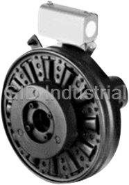
Warner Electric 5180-271-005 EC-375 Electrical Clutch - 90VDC 5/8IN Bore 16FT-LB

WARNER ELECTRIC-CBC-100-1-CLUTCH BRAKE CONTROL
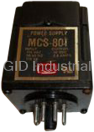
WARNER ELECTRIC-MSC-801-POWER SUPPLY 90VDC.8A 8 PIN INPUT 115VAC 110VA
Warner Electric Quadraline 7000 Series SECO DC Drive, External Signal Chassis, 230VAC Input Line Vol...
Request a Quote

The quote request has been received
Close

Facing challenges or have inquiries? Feel free to contact us!
Call Us +1-469-283-2440
What they say about us
FANTASTIC RESOURCE
One of our top priorities is maintaining our business with precision, and we are constantly looking for affiliates that can help us achieve our goal. With the aid of GID Industrial, our obsolete product management has never been more efficient. They have been a great resource to our company, and have quickly become a go-to supplier on our list!
Bucher Emhart Glass
EXCELLENT SERVICE
With our strict fundamentals and high expectations, we were surprised when we came across GID Industrial and their competitive pricing. When we approached them with our issue, they were incredibly confident in being able to provide us with a seamless solution at the best price for us. GID Industrial quickly understood our needs and provided us with excellent service, as well as fully tested product to ensure what we received would be the right fit for our company.
Fuji
HARD TO FIND A BETTER PROVIDER
Our company provides services to aid in the manufacture of technological products, such as semiconductors and flat panel displays, and often searching for distributors of obsolete product we require can waste time and money. Finding GID Industrial proved to be a great asset to our company, with cost effective solutions and superior knowledge on all of their materials, it’d be hard to find a better provider of obsolete or hard to find products.
Applied Materials
CONSISTENTLY DELIVERS QUALITY SOLUTIONS
Over the years, the equipment used in our company becomes discontinued, but they’re still of great use to us and our customers. Once these products are no longer available through the manufacturer, finding a reliable, quick supplier is a necessity, and luckily for us, GID Industrial has provided the most trustworthy, quality solutions to our obsolete component needs.
Nidec Vamco
TERRIFIC RESOURCE
This company has been a terrific help to us (I work for Trican Well Service) in sourcing the Micron Ram Memory we needed for our Siemens computers. Great service! And great pricing! I know when the product is shipping and when it will arrive, all the way through the ordering process.
Trican Well Service
GO TO SOURCE
When I can't find an obsolete part, I first call GID and they'll come up with my parts every time. Great customer service and follow up as well. Scott emails me from time to time to touch base and see if we're having trouble finding something.....which is often with our 25 yr old equipment.
ConAgra Foods