

 Manufacturers
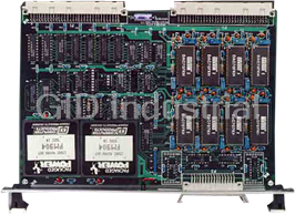
VMIC VMIVME-4116
Description
VMIC VMIVME-4116 8-channel 16-bit Digital-to-Analog Converter Board.
Part Number
VMIVME-4116
Price
Request Quote
Manufacturer
VMIC
Lead Time
Request Quote
Category
Analog Output Modules
Specifications
Altitude
Operation to 10,000 ft
Cooling
Forced air convection
Dimensions
Double height Eurocard (6U) 160 x 233.35 mm
Humidity
20 to 80 percent relative, non-condensing
Power Requirements
2.5 A (maximum) at +5 V
Temperature Operating
0 to +50 °C
Temperature Storage
-20 to +85 °C
Features
- 16-bit DACs
- 8 channels
- Buffered voltage output (±10 V at 5 mA)
- Double-buffered data latches
- Fast settling: 10 µs maximum to ±0.003 percent of FSR
- Front panel fail LED
- High reliability DIN-type output connector
- Jumper-selectable synchronized update control
- Multiplexed programmable outputs on P2 connector for testing analog outputs
- Outputs set to 0.0 V on power up
- Selectable external update control input or software-controlled strobe provides single update strobe for all DAC outputs
Datasheet

Extracted Text
VMIVME-4116 8-Channel 16-bit Resolution Analog Output Board • 8 channels • 16-bit DACs • Fast settling: 10 µs maximum to ±0.003 percent of FSR • Buffered voltage output (±10 V at 5 mA) • Multiplexed programmable outputs on P2 connector for testing analog outputs • Double-buffered data latches • Jumper-selectable synchronized update control • Selectable external update control input or software-controlled strobe provides single update strobe for all DAC outputs • Front panel fail LED • High reliability DIN-type output connector • Outputs set to 0.0 V on power up — Outputs are automatically disconnected from the Ţeld at power up • Double Eurocard form factor • Supports VMIC’s analog expansion and Built-in-Test bus (AMXbus™) that interconnects the P2 connectors of various VMIC ADC and DAC boards and expansion multiplexer boards • Multiplexed programmable outputs for testing analog input multiplexer boards — Requires VMIC ADC board and AMXbus for Built-In-Test VMEbus Access: Address modiŢer bits are INTRODUCTION — The VMIVME-4116 jumper-selectable to support nonprivileged short I/O or Digital-to-Analog Converter (DAC) Board performs supervisory short I/O access. The board is factory digital-to-analog conversion on 16-bit positive true offset conŢgured for supervisory short I/O access. binary or two’s complement coded words, with an analog output range of -10 to +10 V. This provides for a resolution Data Transfer: Data can be written to one of the eight of 305 µV for each digital input of 1 LSB change. The Digital-to-Analog Converters (DACs) in bytes or words buffered output voltage settles to within 1/2 LSB in 10 µs. (via data bits D00 through D15). Bipolar operation (-10 to +10 V output) uses offset binary coding or two’s The DAC offers a Digital-to-Analog Integrated Circuit complement binary coding. (IC) per channel. A Control and Status Register (CSR) is loaded by the processor and this register controls the functioning of the board. The CSR can be read by the processor at any time. The VMIVME-4116 board Ordering Options functional block diagram is shown in Figure 1. Each of the August 13, 1996 800-004116-000 E eight DACs is preceded by double-buffered data latches. VMIVME-4116 The data latches allow versatility in the way the DAC analog Model Number output may be updated. Description 0 to ±10 V Outputs 8-Channel, Double-Buffered, 16-bit Analog Output VMIVME-4116-070 without Built-in-Test and without Output Isolation There are three methods by which new data can be 8-Channel, Double-Buffered, 16-bit Analog Output VMIVME-4116-060 converted by a DAC. Each method is enabled/disabled by with JFET Output Isolation Switches and on-board jumpers and is further controlled by a CSR that Built-in-Test Hardware must be loaded by the user. 8-Channel, Double-Buffered, 16-bit Analog Output VMIVME-4116-050 with Output Isolation Relays and Built-in-Test Hardware FUNCTIONAL CHARACTERISTICS 8-Channel, Double-Buffered, 16-bit Analog Output VMIVME-4116-040 with JFET Output Isolation Switches and No Built-in-Test Hardware Compatibility: The VMIVME-4116 Analog Output 8-Channel, Double-Buffered, 16-bit Analog Output VMIVME-4116-030 Board is a standard, double height, printed circuit board with Output Isolation Relays and No Built-in-Test which is compatible with the VMEbus speciŢcation. Hardware Connector Data Board Address: The physical address for the board Compatible Cable Connector Panduit No. 120-332-435E is selected by 12 DIP switches. VMEbus address lines Strain Relief Panduit No. 100-000-042 A05 through A15 are decoded for board selection. PC Board Header Connector Panduit No. 120-332-033A For Ordering Information, Call: 1-800-322-3616 or 1-256-880-0444 • FAX (256) 882-0859 E-mail: info@vmic.com Web Address: www.vmic.com Copyright © July 1986 by VMIC Specifications subject to change without notice. VMIC ¥ 12090 South Memorial Parkway ¥ Huntsville, Alabama 35803-3308 1 VMIVME-4116 Mode Selection: The operational modes of the board reset initializes all analog outputs to the P3 connector to are selected by setting the following control bits during 0.0 V. The analog test bus outputs are disconnected from a write cycle to the Control and Status Register (CSR). the P2 connector upon system reset. The CSR may be read at any time to verify the current operating mode. The function of each bit in the CSR is Front Panel Fail LED: If an error condition is deŢned as follows. detected during the diagnostics, a front panel Fail LED may be illuminated under software control for a visual D08 — Enables DAC outputs to the P3 failure indication. The LED is illuminated upon power connector up clear (system reset) and is extinguished upon D09 — Initiates digital-to-analog successful diagnostic execution. conversion D10 — Not used Analog Output Channels: Eight analog output D11 to D13 — Test mode control bits channels D14 — Operates Fail LED D15 — Not used The analog output equation for offset binary bipolar operation: (-10 V to +10 V) is V = -10 V + [(Digital Code 10 x 20)] Test Mode: The DAC board may be used in OUT 65536 conjunction with other VMIC boards and VMIC’s AMXbus backplane for extensive fault detection and ELECTRICAL CHARACTERISTICS isolation. There are two dedicated analog signal lines that are used by the DAC board. Loopback tests may be Data Transfer: A16/D8, D16 executed primarily for testing the Analog-to-Digital Converter (ADC) board by utilizing any one of the Analog Output (Voltage output at R = LOAD eight DAC outputs. 2 kW): Bipolar: -10 to +10 V at 5 mA While in a test mode, the eight DAC outputs may be isolated from the P3 output connector so that Output Impedance: user-connected devices are not affected by testing. Standard model — 0.15 W Also, the testing may be performed in conjunction with Optional output isolation switches (JFET switch) real-time control of the user-connected devices, —100 W providing real-time fault detection capabilities. Optional output isolation relays — 0.2 W Analog Input Test Mode: Any one of the eight D/A Input Code: analog outputs may be multiplexed to an analog test bus Bipolar: Offset binary, two’s complement binary (Test Bus 1). This analog bus is used to verify the operation of the analog input multiplexer expansion Resolution: 16 bits board that supports Built-in-Test. VMIC’s AMXbus supports the analog Built-in-Test concepts. Accuracy (Typical at 25 °C)* Analog Output Testing: Any one of the eight analog Gain Error: Adjusted to ±1/2 LSB outputs may be switched to the analog output test bus Offset: (Test Bus 2). This bus is routed over the P2 AMXbus Bipolar: Adjusted to ±1/2 LSB analog backplane to a VMIC ADC which veriŢes the analog output of each of the eight DACs on the Differential Linearity Error: ±0.003 percent of VMIVME-4116 board. FSR (Full-Scale Range) Linearity Error: ±0.0015 percent of FSR System Reset: Application of the system reset signal via the VMEbus initializes the board into a state with all Drift (Typical Unless Otherwise Stated): analog outputs disconnected from the P3 connector if either the JFET switch or output isolation relay options Gain Drift: ±10 PPM/°C are installed. If no output isolation switches or relays Zero Drift: ±5 PPM of FSR/°C are installed (see the Ordering Options), then system 2 For Ordering Information, Call: 1-800-322-3616 or 1-256-880-0444 ¥ FAX (256) 882-0859 VMIVME-4116 AMXbus backplanes are available from VMIC as Differential Linearity Over Temperature: standard products. +0.009 to -0.006 percent of FSR (maximum) Linearity Error Over Temperature: ±0.006 percent Output Connector: Board connector (P3) — of FSR (maximum) Panduit male connector type 120-332-033A Output cable connector — female type Settling Time: 10 µs to ±1/2 LSB 120-332-435E Output connector strain relief 100-000-042 Monotonicity: 14 bits monotonic over full temperature range TRADEMARKS AMXbus is a trademark of and the VMIC logo is a Power Requirements: 2.5 A (maximum) at +5 V registered trademark of VMIC. Other registered trademarks are the property of their respective owners. PHYSICAL/ENVIRONMENTAL Temperature: 0 to +50 °C, operating -20 to +85 °C, storage *Accuracy stated without analog output isolation switches installed. The Built-in-Test hardware features analog output Humidity: 20 to 80 percent relative, noncondensing isolation switches for all eight channels that can be turned ON/OFF by software commands. These switches are in a series with the analog output and the user-connected device at the P3 Altitude: Operation to 10,000 ft connector. These switches have an ON resistance of approximately 100 W (maximum). If the user-connected load Cooling: Forced air convection does not have a high impedance input, then a possible voltage division error is introduced. For example, if R(LOAD) is 10 kW, Dimensions: Double height Eurocard (6U) 160 x then a 1 percent error is introduced. R(LOAD) should be 10 MW 233.35 mm or greater for an error of 0.001 percent or less. VMEbus Connector: Two 96-pin DIN connectors. VMIC utilizes the user I/O pins on the P2 connector to support an analog bus (AMXbus). A variety of APPLICATION AND CONFIGURATION GUIDES — The following Application and Configuration Guides are available from VMIC to assist the user in the selection, specification, and implementation of systems based in VMIC’s products. Title Document No. Digital Input Board Application Guide 825-000000-000 Change-of-State Board Application Guide 825-000000-002 Digital I/O (with Built-in-Test) Product Line Description 825-000000-003 Synchro/Resolver (Built-in-Test) Subsystem ConŢguration Guide 825-000000-004 Analog I/O Products (with Built-in-Test) ConŢguration Guide 825-000000-005 Connector and I/O Cable Application Guide 825-000000-006 Data Acquisition Noise Reduction 825-000000-026 VMIC ¥ 12090 South Memorial Parkway ¥ Huntsville, Alabama 35803-3308 3 VMIVME-4116 PROGRAM OPERATION AND EXTERNAL UPDATE CNTL LOGIC CNTL UPDATE P3 A0 CH0 A0 16-bit 16-bit A7 OPTIONAL DAC No. 5 DAC No. 1 ANALOG OUT ISOLATION DAC DAC SWITCHES SEL SEL CH7 A7 16-bit 16-bit A5 A1 DAC No. 2 DAC No. 6 DAC DAC SEL SEL 16-bit 16-bit A6 A2 DAC No. 3 DAC No. 7 DAC DAC SEL SEL C 16-bit 16-bit O A3 DAC No. 4 DAC No. 8 A7 M V P L M A O DAC DAC E T G SEL SEL b I I u A7 B C DATA BUS s A0 I L I ADDRESS T SELECT 8-CH MUX Y SWITCHES ADDRESS DAC CONTROL SEL LOGIC 8 CSR TEST MODE P2 SELECT A0 TEST DUAL TEST A0 SPDT SELECT AIN TEST TEST AIN SWITCH Figure 1. VMIVME-4116 Board Functional Block Diagram VMEbus VMIVME-41xx VMIVME-41xx VMIVME-31xx ANALOG ANALOG SERIES OUTPUT OUTPUT ADC BOARD BOARD AMXbus ANALOG OUTPUT TEST BUS 16 SINGLE-ENDED ANALOG ANALOG FRONT PANEL INPUTS OUTPUTS OUTPUTS The AMXbus backplane may be replaced with a standard P2 VME expansion bus and user-supplied jumper wires on the user I/O pins. The VMIC AMXbus backplane is available in printed circuit form in 5, 9, or 19 slots. The AMXbus backplane is designed to provide enhanced noise immunity and is recommended for most applications. Figure 2. Model 41xx Series Built-in-Test Configuration 4 For Ordering Information, Call: 1-800-322-3616 or 1-256-880-0444 ¥ FAX (256) 882-0859
Frequently asked questions
How does Industrial Trading differ from its competitors?

Is there a warranty for the VMIVME-4116?
Which carrier will Industrial Trading use to ship my parts?
Can I buy parts from Industrial Trading if I am outside the USA?
Which payment methods does Industrial Trading accept?
Why buy from GID?

Quality
We are industry veterans who take pride in our work

Protection
Avoid the dangers of risky trading in the gray market

Access
Our network of suppliers is ready and at your disposal

Savings
Maintain legacy systems to prevent costly downtime

Speed
Time is of the essence, and we are respectful of yours
Related Products
VMIC VMIVME-400 16-Channel 12-bit Digital-Analog-Analog Converter Board
VMIC VMIVME-4140 32-Channel 12-Bit Analog Output Board
Request a Quote

The quote request has been received
Close

Facing challenges or have inquiries? Feel free to contact us!
Call Us +1-469-283-2440
What they say about us
FANTASTIC RESOURCE
One of our top priorities is maintaining our business with precision, and we are constantly looking for affiliates that can help us achieve our goal. With the aid of GID Industrial, our obsolete product management has never been more efficient. They have been a great resource to our company, and have quickly become a go-to supplier on our list!
Bucher Emhart Glass
EXCELLENT SERVICE
With our strict fundamentals and high expectations, we were surprised when we came across GID Industrial and their competitive pricing. When we approached them with our issue, they were incredibly confident in being able to provide us with a seamless solution at the best price for us. GID Industrial quickly understood our needs and provided us with excellent service, as well as fully tested product to ensure what we received would be the right fit for our company.
Fuji
HARD TO FIND A BETTER PROVIDER
Our company provides services to aid in the manufacture of technological products, such as semiconductors and flat panel displays, and often searching for distributors of obsolete product we require can waste time and money. Finding GID Industrial proved to be a great asset to our company, with cost effective solutions and superior knowledge on all of their materials, it’d be hard to find a better provider of obsolete or hard to find products.
Applied Materials
CONSISTENTLY DELIVERS QUALITY SOLUTIONS
Over the years, the equipment used in our company becomes discontinued, but they’re still of great use to us and our customers. Once these products are no longer available through the manufacturer, finding a reliable, quick supplier is a necessity, and luckily for us, GID Industrial has provided the most trustworthy, quality solutions to our obsolete component needs.
Nidec Vamco
TERRIFIC RESOURCE
This company has been a terrific help to us (I work for Trican Well Service) in sourcing the Micron Ram Memory we needed for our Siemens computers. Great service! And great pricing! I know when the product is shipping and when it will arrive, all the way through the ordering process.
Trican Well Service
GO TO SOURCE
When I can't find an obsolete part, I first call GID and they'll come up with my parts every time. Great customer service and follow up as well. Scott emails me from time to time to touch base and see if we're having trouble finding something.....which is often with our 25 yr old equipment.
ConAgra Foods