

 Manufacturers
VMIC VMIVME-4140
Description
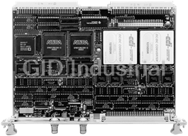
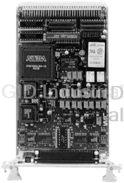
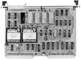
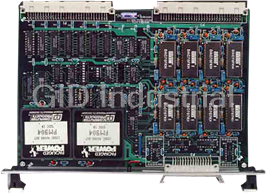
VMIC VMIVME-4140 32-Channel 12-Bit Analog Output Board
Part Number
VMIVME-4140
Price
Request Quote
Manufacturer
VMIC
Lead Time
Request Quote
Category
Analog Output Modules
Specifications
12 µs, step
50 percent SPAN
18 µs, step
100 percent SPAN
BIT Switch Impulse
1 µV-s, maximum spike during channel change
Cooling
Normal VMEbus chassis forced air circulation
Dimensions
6U single slot Eurocard form factor
Interchannel Crosstalk Rejection
70 dB minimum, DC - 1 kHz
Long Term
±45 ppm setting ±30 ppm SPAN ±50 µV, maximum drift per
Maximum Sustainable VMEbus Data Transfer Rate
200 kHz,
Relative Humidity
20% to 80%, non condensing
Temperature
0 to +65 °C, operating
Temperature Effect
±35 ppm setting ±25 ppm SPAN ±30 µV,maximum drift per °C
Transition Impulse
5 µV-s, maximum spike during data transition
Weight (Mass)
0.7 kgm maximum
Write Access Time
500 ns maximum at data transfer rates less than
Features
- 0.8?output impedance
- 10mA maximum output current per channel
- 32 analog output channels
- Automatic calibration initiated by reset or by software command
- Automatic test equipment (ATE)
- Control systems
- Discrete wi Self-test
- Extensive onboard diagnostic testing capability
- Front panel analog output connector
- Front panel reference voltage access
- Front panel status LED
- One 12-bit D/A converter (DAC) per output channel
- outputs
- Precision analog stimulus
- Random update (nonscanning)
- required
- self-testing and ±10V) software selectable
- Single reference potentiometer – no other manual calibration
- Software or external synchronous update of double-buffered
- Stems-Data acquisition sy
- Unipolar (0 to +10V, 0 to +5V, 0 • to +2.5V) or bipolar (±2.5, ±5 or mass-terminated
Datasheet

Extracted Text
GE Fanuc Automation VMIVME-4140 Specifications 32-Channel 12-bit Analog Output Board Features: • 32 analog output channels • Front panel status LED – 10mA maximum output current per channel • Front panel analog output connector – One 12-bit D/A converter (DAC) per output channel • Front panel reference voltage access • 0.8Ω output impedance • Applications • Random update (nonscanning) – Data acquisition systems • Software or external synchronous update of double-buffered – Control systems outputs – Precision analog stimulus – Automatic test equipment (ATE) • Single reference potentiometer – no other manual calibration required • Automatic calibration initiated by reset or by software command • Unipolar (0 to +10V, 0 to +5V, 0 to +2.5V) or bipolar (±2.5, ±5 and ±10V) software selectable • Discrete wire or mass-terminated cables • Self-test – Extensive onboard diagnostic testing capability – Outputs can be disconnected from the field for offline – PMC expansion slots – self-testing VMIVME-4140 32-Channel 12-bit Analog Output Board Front Panel Reference Voltage Access: An isolated BNC connector on the front panel allows access to the internal Ordering Options reference voltage. Front panel access to the corresponding July 17, 2006 800-004140-000 C A B C D E F reference voltage adjustment is provided. VMIVME-4140 – 0 0 0 Calibration: When autocalibration is initiated, either by a A = 0 (Option reserved for future use.) system reset or software command, an embedded DSP loads B = Output Connector Type calibration output values into each of the output DACs which 0 = Discrete Wire are read back into the DSP through a 16-bit ADC. This is 1 = IDC (Mass-Terminal) repeated until a sufficient number of calibration points have C = Number of Channels 0 = 32 Channels been measured. A calibration table consisting of offset and 1 = 16 Channels gain corrections for each of the 32 outputs in each of the D = 0 (Option reserved for future use) six voltage ranges is compiled and stored in RAM. These E = 0 (Option reserved for future use) correction factors are recalled each time an output is F = Conformal Coating changed. 0 = Standard VME front panel without conformal coating 1 = Reserved System Reset: After a system reset, all outputs are in the 2 = Standard VME front panel with conformal coating offline mode, all Control Registers are in their default state, IDC Output Connector Data self-test is initiated, and autocalibration is initiated. Mating Cable Connector Panduit No. 120-964-435 Strain Relief Panduit No. 100-000-072 VMEbus Compliance: This board complies with the VMEbus PC Board I/O Connector Panduit No. 120-964-033A specification (ANSI/IEEE STD 1014-1987 IEC 821 and 297) Discrete Wire Output Connector Data with the following mnemonics: Mating Connector AMP No. 925486-1 Addressing Mode Responding Address Modifiers Female Crimp Contacts* AMP No. 530151-6 A32 $09 (Extended nonprivileged data Connector Shell Housing Harting No. 09 03 096 0501 PC Board Connector Panduit No. 120-964-033A access) or $0D (Extended supervisory *An AMP crimp tool part number is 90301-2. data access) Front Panel Reference Voltage and Front Panel External Sync A24 $39 (Standard nonprivileged data Connector Data access) or $3D (Standard supervisory Front Panel Connector AMP No. 22726-3 data access) Note A16 $29 (Short nonprivileged I/O access) or Panduit is also known as ITW/Pancon. $2D (Short supervisory I/O access) For Ordering Information, Call: Data Accesses: D16, D08(EO) 1-800-322-3616 or 1-256-880-0444 • FAX (256) 882-0859 Email: info.embeddedsystems@gefanuc.com Board Address: The base VMEbus address is set by Web Address: www.gefanuc.com/embedded configuration of a jumper field. A jumper exists for each of Copyright © 2006 by GE Fanuc Embedded Systems the addresses A31 through A7; the address space occupied Specifications subject to change without notice. by this board is 128 consecutive bytes. VMEbus Compliance: Address modifier bits are jumper Functional Characteristics selected and decoded to support nonprivileged, supervisory, Introduction: The VMIVME-4140 Analog Output Board and either nonprivileged or supervisory board accesses. provides 32 high quality analog output channels with 12-bit Output Data Transfer: Output data is stored in 32 16-bit resolution, and can source or sink 10 mA at ±10 V. Each registers. The board can be software configured to accept output has a dedicated D/A Converter (DAC) assigned to it. either two's complement or offset binary data. Output The analog outputs can be disconnected from the field wiring change may be initiated by register access, however, outputs for offline testing. Calibration and self-test are initiated by a are double buffered which allows all channels to be VMEbus system reset or by execution of a software synchronously updated by either a software or external command. During calibration, a table of offset and gain trigger. coefficients is compiled and stored in RAM. There is an entry for offset and gain corresponding to each of the 32 channels configured in each of the six output voltage ranges. Self-Test: Self-Test is run automatically after system reset. The Self-Test Register indicates success or failure and can indicate the channel which has failed. Front Panel Status LED: The LED is illuminated after a system reset. The LED is extinguished on the successful completion of self-test and autocalibration. The LED can also be turned ON and OFF under software control. 2 VMIVME-4140 32-Channel 12-bit Analog Output Board Address Map: Accuracy, Initial : Maximum error at +25°C: Offset from base address ±0.03 percent setting ±0.025 percent SPAN ±1.5mV Gain Error Offset Error Example: for a setting of +2.000V on the ±5V range: $0000 Registers, Max Error = (±0.03% x 2.000V) ± (0.025% x 10V) ±1.5 Commands and = ±0.6mV ± 2.5mV ± 1.5 Reserved = ±4.6mV $0040 Note: Initial accuracy is established when the board is Output Data channel-calibrated directly after reference calibration. Accuracy Stability $0080 Temperature Effect: ±35 ppm setting ±25 ppm SPAN ±30µV, maximum drift per °C Long Term: ±45 ppm setting ±30 ppm SPAN ±50µV, Electrical Characteristics maximum drift per 1,000 hr (At +25° C and rated power supplies unless otherwise noted.) Interchannel Crosstalk Rejection: 70 dB minimum, Outputs: Thirty-two or sixteen single-ended; one DAC per DC - 1 kHz channel Output Noise : Full-Scale Output: ±10 V, ±5 V, ±2.5 V, 0 to +2.5 V, 0 to +5 V, 4mV p-p maximum at 3σ (10 Hz to 10 kHz) 0 to +10 V (software selectable) 30mV p-p maximum at 3σ (10 Hz to 20 MHz) Output Code: Each 12-bit DAC accepts digital codes in offset Note: Output noise is specified at 3σ standard deviations, binary or two’s complement (software selectable) which includes 99.7 percent of all noise peaks for a normal distribution. Glitch (transition) and BIT-switching noise is not Resolution: 12 bits included. Output Impedance: < 0.8Ω, online Transition Impulse: 5µV-s, maximum spike during data > 10Ω, offline transition Output Current: ±10mA, over the entire output voltage BIT Switch Impulse: 1µV-s, maximum spike during channel range change Output Short Circuit Protection: Indefinite Settling Time (0.01 Percent): short-to-common; transient overvoltage protected to ±25V 18µs, step = 100 percent SPAN (for one second) 12µs, step = 50 percent SPAN Transfer Characteristics Access Time N DATA Write Access Time: 500ns maximum at data transfer rates E =E +( ×E ) OUT OUTMIN SPAN 4,096 less than 200 kHz Where: Maximum Sustainable VMEbus Data Transfer Rate: EOUT = Channel output voltage 200 kHz, minimum EOUTMIN = Negative end of range NDATA = Channel data from VMEbus Note: Access time is specified as the delay from active Data E = Positive end of range minus negative end of range Strobes to DTACK. SPAN Example: for the ±5 V range: Physical/Environmental Specifications N DATA E =−5V+( ×10V) OUT External Trigger : 4,096 Polarity Programmable Level TTL, VIH = 2.0V; VIL = 0.8V Note: Initial accuracy is established when the board is Pulse Width 1µs, minimum channel-calibrated directly after reference calibration. Note: May be accessed from a front panel BNC connector or Differential Nonlinearity: 0.030 percent SPAN, maximum. from the VMEbus P2 connector. Monotonic over the operating temperature range. Dimensions: 6U single slot Eurocard form factor Integral Nonlinearity: 0.030 percent SPAN, maximum Height 9.2 in. (233.4mm) (referenced to best fit straight line) Depth 6.3 in. (160mm) Thickness 0.8 in. (20.3mm) 3 VMIVME-4140 32-Channel 12-bit Analog Output Board Weight (Mass): 0.7 kgm maximum Power Requirements: +5VDC at 4.0A maximum; outputs fully loaded Temperature: 0 to +65° C, operating Altitude: Operation to 3,000m -25 to +85° C, storage MTBF: 107,400 hours (217F) Relative Humidity: Trademarks 20% to 80%, noncondensing All registered trademarks are the property of their respective Cooling: Normal VMEbus chassis forced air circulation owners. 4 VMIVME-4140 32-Channel 12-bit Analog Output Board CONTROL LOGIC TYPICAL EEPROM 1 OF 32 ANALOG OUTPUTS FRONT ±10 V (±10 mA) PANEL P3 ELECTRONIC OUTPUT SWITCH BUFFER P1/P2 VMEbus 32 12-bit INTERFACE DATA AND ADDRESS BUS DAC LOGIC V M 12-bit DATA E RIGHT- DSP JUSTIFIED b u s 32 32-TO-1 16-bit ANALOG ADC MUX DC-TO-DC +5 VDC ±15 VDC POWER CONVERTERS TYPICAL 1 OF 32 OUTPUT MONITORS VOLTAGE REFERENCE SELF-TEST NETWORK Figure 1. VMIVME-4140 Functional Block Diagram GE Fanuc Embedded Systems Information Centers Additional Resources Americas: For more information, please visit the Huntsville, AL 1 800 322-3616 GE Fanuc Embedded Systems web site at: 1 (256) 880-0444 www.gefanuc.com/embedded Camarillo, CA 1 (805) 987-9300 Greenville, SC 1 (864) 627-8800 Richardson, TX 1 (972) 671-1972 Europe, Middle East and Africa: Edinburgh, UK 44 (131) 561-3520 Paris, France 33 (1) 4324 6007 5
Frequently asked questions
How does Industrial Trading differ from its competitors?

Is there a warranty for the VMIVME-4140?
Which carrier will Industrial Trading use to ship my parts?
Can I buy parts from Industrial Trading if I am outside the USA?
Which payment methods does Industrial Trading accept?
Why buy from GID?

Quality
We are industry veterans who take pride in our work

Protection
Avoid the dangers of risky trading in the gray market

Access
Our network of suppliers is ready and at your disposal

Savings
Maintain legacy systems to prevent costly downtime

Speed
Time is of the essence, and we are respectful of yours
Related Products
VMIC VMIVME-400 16-Channel 12-bit Digital-Analog-Analog Converter Board
VMIC VMIVME-4116 8-channel 16-bit Digital-to-Analog Converter Board.
Request a Quote

The quote request has been received
Close

Facing challenges or have inquiries? Feel free to contact us!
Call Us +1-469-283-2440
What they say about us
FANTASTIC RESOURCE
One of our top priorities is maintaining our business with precision, and we are constantly looking for affiliates that can help us achieve our goal. With the aid of GID Industrial, our obsolete product management has never been more efficient. They have been a great resource to our company, and have quickly become a go-to supplier on our list!
Bucher Emhart Glass
EXCELLENT SERVICE
With our strict fundamentals and high expectations, we were surprised when we came across GID Industrial and their competitive pricing. When we approached them with our issue, they were incredibly confident in being able to provide us with a seamless solution at the best price for us. GID Industrial quickly understood our needs and provided us with excellent service, as well as fully tested product to ensure what we received would be the right fit for our company.
Fuji
HARD TO FIND A BETTER PROVIDER
Our company provides services to aid in the manufacture of technological products, such as semiconductors and flat panel displays, and often searching for distributors of obsolete product we require can waste time and money. Finding GID Industrial proved to be a great asset to our company, with cost effective solutions and superior knowledge on all of their materials, it’d be hard to find a better provider of obsolete or hard to find products.
Applied Materials
CONSISTENTLY DELIVERS QUALITY SOLUTIONS
Over the years, the equipment used in our company becomes discontinued, but they’re still of great use to us and our customers. Once these products are no longer available through the manufacturer, finding a reliable, quick supplier is a necessity, and luckily for us, GID Industrial has provided the most trustworthy, quality solutions to our obsolete component needs.
Nidec Vamco
TERRIFIC RESOURCE
This company has been a terrific help to us (I work for Trican Well Service) in sourcing the Micron Ram Memory we needed for our Siemens computers. Great service! And great pricing! I know when the product is shipping and when it will arrive, all the way through the ordering process.
Trican Well Service
GO TO SOURCE
When I can't find an obsolete part, I first call GID and they'll come up with my parts every time. Great customer service and follow up as well. Scott emails me from time to time to touch base and see if we're having trouble finding something.....which is often with our 25 yr old equipment.
ConAgra Foods