

 Manufacturers
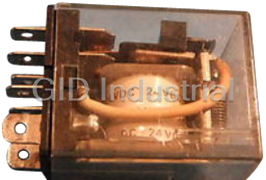
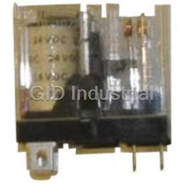
OMRON LY124VDC
Description
OMRON-LY124VDC-Relay, DPDT, 20A
Part Number
LY124VDC
Price
Request Quote
Manufacturer
OMRON
Lead Time
Request Quote
Category
Relays
Specifications
Ambient temperature Operating
LY1, LY2, LY3: -25° to 55°C; LY4
Carry Current
7A
Contact Material
Ag-Alloy
Contact resistance
50 mO max.
Dielectric strength
1,000 VAC, 50/60 Hz for 1 minute between contacts of same polarity
2,000 VAC, 50/60 Hz for 1 minute
Humidity
35 to 85% RH
Inductive load
(p.f.
Inductive load(p.f.
0.4)(L/R
Insulation resistance
100 MO min. (at 500 VDC)
Max. operating current
7A
Max. Operating Voltage
250 VAC 125 VDC
Max. switching capacity
Resistive Load 550 VA 120 W
Min. permissible load
10 mA, 5 VDC
Operate time
25 ms max
Operating frequency M Mechanically
18,000 operations/hour
Operating frequency Under rated load
1,800 operations/hour
Release time
25 ms max.
Resistive load (p.f.1)
5 A at 110 VAC 5 A at 24 VDC
Service Life Electrically
See “Characteristic Data”
Service Life Mechanically
AC: 50 million operations min. (at operating frequency of 18,000 operations/hour)
Shock Malfunction durability
200 m/s2(approx. 20 G)
Shock Mechanical durability
1,000 m/s2(approx. 100 G)
Vibration Malfunction durability
10 to 55 Hz, 1.00 mm (0.04 in) double amplitude
Vibration Mechanical durability
10 to 55 Hz, 1.00 mm (0.04 in) double amplitude
Weight
SPDT, DPDT: Approx. 40 g (1.41 oz), 3PDT: Approx. 50 g (1.76 oz)
Features
- Arc barrier equipped.
- CE marks included on non-PCB mount versions
- Choose models with single or bifurcated contacts,
- High dielectric strength (2,000 VAC).
- LED indicator, diode surge suppression,
- Long dependable service life assured by Ag-Alloy contacts.
- push-to-test button, or RC circuit.
- UL, CSA, and TUV approvals on all standard LY Relays.
Datasheet

Extracted Text
General Purpose Relay LY • Arc barrier equipped. High dielectric strength (2,000 VAC). Long dependable service life assured by Ag-Alloy contacts. Choose models with single or bifurcated contacts, LED indicator, diode surge suppression, push-to-test button, or RC circuit. UL, CSA, and TUV approvals on all standard LY Relays. CE marks included on non-PCB mount versions. Ordering Information To Order: Select the part number and add the desired coil voltage rating (e.g., LY1-DC6). Type Terminal Contact Model form Single contact Bifurcated contact Standard Upper Standard Upper bracket mounting bracket mounting mounting bracket mounting bracket Standard Plug-in/solder SPDT LY1 LY1F — — DPDT LY2 LY2F LY2Z LY2ZF 3PDT LY3 LY3F — — 4PDT LY4 LY4F — — PCB SPDT LY1-0 — — — DPDT LY2-0 — LY2Z-0 — 3PDT LY3-0 — — — 4PDT LY4-0 — — — LED indicator Plug-in/solder SPDT LY1N — — — DPDT LY2N — LY2ZN — 3PDT LY3N — — — 4PDT LY4N — — — Diode surge SPDT LY1-D — — — suppression DPDT LY2-D — LY2Z-D — 3PDT LY3-D — — — 4PDT LY4-D — — — LED indicator SPDT LY1N-D2 — — — and diode surge DPDT LY2N-D2 — LY2ZN-D2 — suppression 4PDT LY4N-D2 — — — RC circuit SPDT LY1-CR — — — DPDT LY2-CR — LY2Z-CR — LED indicator SPDT LY1N-CR — — — and RC circuit DPDT LY2N-CR — LY2ZN-CR — Note: 1. Types with specifications other than those listed are available. Contact your Omron Sales representative. 2. To order connecting sockets and mounting tracks, see “Accessories” section. 3. Relays with RC circuit are only available in AC coil voltages of 100 VAC or greater. General Purpose Relay LY 307 Type Terminal Contact Model form Single contact Bifurcated contact Standard Upper Standard Upper bracket mounting bracket mounting mounting bracket mounting bracket Push-to-test Plug-in/solder SPDT LY1l4 — — — button DPDT LY2l4 — LY2Zl2 — 3PDT LY3l4 — — — 4PDT LY4l4 — — — LED indicator and Plug-in/solder DPDT LY2l4N — LY2Zl2N — push-to-test button 4PDT LY4l4N — — — Note: 1. Types with specifications other than those listed are available. Contact your Omron Sales representative. 2. To order connecting sockets and mounting tracks, see “Accessories” section. ■ Accessories Connecting Sockets To Order: Select the appropriate part numbers for sockets, clips, and mounting tracks (if required) from the following charts. Track Mounted Sockets Relay Socket* Relay hold-down clip Mounting track Standard RC circuit SPDT PTF08A-E PYC-A1 Y92H-3 PFP-100N/PFP-50N & DPDT PFP-M or PFP-100N2 3PDT PTF11A PFP-S (Option spacer) 4PDT PTF14A-E * Track mounted socket can be used as a front connecting socket. Back Connecting Sockets Relay Solder Wire wrap Relay hold-down clip Socket Mounting Plate terminal terminal Standard Push-to-test RC circuit Mtg. plate 1 10 12 18 socket socket SPDT PT08 PT08QN PYC-P PYC-P2 PYC-1 PYC-S PYP-1 – – PYP-18 DPDT 3PDT PT11 PT11QN PTP-1-3 – PTP-12 – 4PDT PT14 PT14QN PTP-1 PTP-10 – – Note: Types PYP-18, PTP-12 and PTP-10 may be cut to any desired length. Relay PC terminal socket Relay hold-down clip Standard Push-to-test RC circuit SPDT PT08-0 PYC-P PYC-P2 PYC-1 DPDT 3PDT PT11-0 4PDT PT14-0 308 General Purpose Relay LY Specifications ■ Contact Data Load Single contact Bifurcated contact SPDT DPDT, 3PDT, 4PDT DPDT Resistive load Inductive load Resistive load Inductive load Resistive load Inductive load (p.f. = 1) (p.f. = 0.4) (p.f. = 1) (p.f. = 0.4) (p.f. = 1) (p.f. = 0.4) (L/R = 7 ms) (L/R = 7 ms) (L/R = 7 ms) Rated load 15 A at 110 VAC 10 A at 110 VAC 10 A at 110 VAC 7.5 A at 110 VAC 5 A at 110 VAC 4 A at 110 VAC 15 A at 24 VDC 7 A at 24 VDC 10 A at 24 VDC 5 A at 24 VDC 5 A at 24 VDC 4 A at 24 VDC Contact material Ag-Alloy Carry current 15 A 10 A 7 A Max. operating 250 VAC voltage 125 VDC Max. operating 15 A 10 A 7 A current Max. switching 1,700 VA 1,100 VA 1,100 VA 825 VA 550 VA 440 VA capacity 360 W 170 W 240 W 120 W 120 W 100 W Min. permissible 100 mA, 5 VDC 10 mA, 5 VDC load ■ Coil Data 1- and 2-pole Types – AC Rated Rated current (mA) Coil Coil inductance Pick-up Dropout Maximum Power voltage (V) resistance (ref. value) (H) voltage voltage voltage consumption (Ω) (VA, W) 50 Hz 60 Hz Armature Armature (% of rated voltage) OFF ON 6 214.10 183 12.20 0.04 0.08 80% max. 30% min. 110% Approx. 1.00 to 1.20 12 106.50 91 46 0.17 0.33 (60 Hz) 24 53.80 46 180 0.69 1.30 50 25.70 22 788 3.22 5.66 100/110 11.70/12.90 10/11 3,750 14.54 24.60 Approx. 0.90 to 1.10 110/120 9.90/10.80 8.40/9.20 4,430 19.20 32.10 (60 Hz) 200/220 6.20/6.80 5.30/5.80 12,950 54.75 94.07 220/240 4.80/5.30 4.20/4.60 18,790 83.50 136.40 1- and 2-pole Types – DC Rated Rated current (mA) Coil Coil inductance Pick-up Dropout Maximum Power voltage (V) resistance (ref. value) (H) voltage voltage voltage consumption (Ω) (VA, W) Armature Armature (% of rated voltage) OFF ON 6 150 40 0.16 0.33 80% max. 10% min. 110% Approx. 0.90 12 75 160 0.73 1.37 24 36.90 650 3.20 5.72 48 18.50 2,600 10.60 21 100/110 9.10/10 11,000 45.60 86.20 Note: 1. The rated current and coil resistance are measured at a coil temperature of 23°C (73°F) with tolerances of +15%, -20% for AC rated current, and ±15% for DC rated coil resistance. 2. The AC coil resistance and inductance are reference values at 60 Hz. 3. The performance characteristics are measured at a coil temperature of 23°C (73°F). 4. Class B coil insulation is available. General Purpose Relay LY 309 3-pole Type – AC Rated Rated current (mA) Coil Coil inductance Pick-up Dropout Maximum Power voltage (V) resistance (ref. value) (H) voltage voltage voltage consumption (Ω) (VA, W) 50 Hz 60 Hz Armature Armature (% of rated voltage) OFF ON 6 310 270 6.70 0.03 0.05 80% max. 30% min. 110% Approx. 1.60 to 2.00 12 159 134 24 0.12 0.21 (60 Hz) 24 80 67 100 0.44 0.79 50 38 33 410 2.24 3.87 100/110 15.90/18.30 13.60/15.60 2,300 10.50 18.50 120 17.30 14.8 2,450 11.50 20.60 200/220 10.50/11.60 9.00/9.90 8,650 34.80 59.50 240 9.40 8 10,400 38.60 74.60 3-pole Type – DC Rated Rated current (mA) Coil Coil inductance Pick-up Dropout Maximum Power voltage resistance (ref. value) (H) voltage voltage voltage consumption (V) (Ω) (VA, W) Armature Armature (% of rated voltage) OFF ON 6 234 25.70 0.11 0.21 80% max. 10% min. 110% Approx. 1.40 12 112 107 0.45 0.98 24 58.60 410 1.89 3.87 48 28.20 1,700 8.53 13.90 100/110 12.70/13 8,500 29.60 54.30 4-pole Type – AC Rated Rated current (mA) Coil Coil inductance Pick-up Dropout Maximum Power voltage (V) resistance (ref. value) (H) voltage voltage voltage consumption (Ω) (VA, W) 50 Hz 60 Hz Armature Armature (% of rated voltage) OFF ON 6 386 330 5 0.02 0.04 80% max. 30% min. 110% Approx. 1.95 to 2.50 12 199 170 20 0.10 0.17 (60 Hz) 24 93.60 80 78 0.38 0.67 50 46.80 40 350 1.74 2.88 100/110 22.50/25.50 19/21.80 1,800 10.50 17.30 120 19.00 16.40 2,200 9.30 19 200/220 11.50/13.10 9.80/11.20 6,700 33.10 57.90 240 11.00 9.50 9,000 33.20 63.40 4-pole Type – DC Rated Rated current (mA) Coil Coil inductance Pick-up Dropout Maximum Power voltage (V) resistance (ref. value) (H) voltage voltage voltage consumption (Ω) (VA, W) Armature Armature (% of rated voltage) OFF ON 6 240 25 0.09 0.21 80% max. 10% min. 110% Approx. 1.50 12 120 100 0.39 0.84 24 69 350 1.41 2.91 48 30 1,600 6.39 13.60 100/110 15/15.90 6,900 32 63.70 Note: 1. The rated current and coil resistance are measured at a coil temperature of 23°C (73°F) with tolerances of +15%, -20% for AC rated current, and ±15% for DC rated coil resistance. 2. The AC coil resistance and inductance are reference values at 60 Hz. 3. The performance characteristics are measured at a coil temperature of 23°C (73°F). 4. Class B coil insulation is available. 310 General Purpose Relay LY ■ Characteristics Contact resistance 50 mΩ max. Operate time 25 ms max. Release time 25 ms max. Operating frequency Mechanically 18,000 operations/hour Under rated load 1,800 operations/hour Insulation resistance 100 MΩ min. (at 500 VDC) Dielectric strength 2,000 VAC, 50/60 Hz for 1 minute 1,000 VAC, 50/60 Hz for 1 minute between contacts of same polarity Vibration Mechanical durability 10 to 55 Hz, 1.00 mm (0.04 in) double amplitude Malfunction durability 10 to 55 Hz, 1.00 mm (0.04 in) double amplitude 2 Shock Mechanical durability 1,000 m/s (approx. 100 G) 2 Malfunction durability 200 m/s (approx. 20 G) Ambient temperature Operating LY1, LY2, LY3: -25° to 55°C; LY4 =-25° to 40°C Humidity 35 to 85% RH Service Life Mechanically AC: 50 million operations min. (at operating frequency of 18,000 operations/hour) DC: 100 million operations min. (at operating frequency of 18,000 operations/hour) Electrically See “Characteristic Data” Weight SPDT, DPDT: Approx. 40 g (1.41 oz), 3PDT: Approx. 50 g (1.76 oz) 4PDT: Approx. 70 g (2.47 oz) Note: Data shown are of initial value. ■ Characteristic Data Maximum switching capacity LY1 LY2 LY3, LY4 LY2Z Rated operating voltage (V) Rated operating voltage (V) Rated operating voltage (V) Rated operating voltage (V) Electrical service life LY1 LY2 LY3, LY4 LY2Z Switching current (A) Switching current (A) Switching current (A) Switching current (A) General Purpose Relay LY 311 6 Rated operating current (A) Service Life (X10 operations) 6 Rated operating current (A) Service Life (X10 operations) 6 Rated operating current (A) Service Life (X10 operations) 6 Rated operating current (A) Service Life (X10 operations) Dimensions Unit: mm (inch) ■ Relays LY1 Terminal LY2 Terminal arrangement arrangement (Bottom view) (Bottom view) LY3 Terminal LY4 Terminal arrangement arrangement (Bottom view) (Bottom view) LY1-0, LY2-0, LY3-0, LY4-0 Mounting holes for LY1-0, LY2-0, LY3-0, LY4-0 (Bottom view) Note: The above drawing shows LY2-0. With LY1-0, SPTD DPDT 3PDT 4PDT dimension “*” should read as eight 6.35 (.25). LY1F, LY2F Mounting LY3F Mounting holes holes Note: The above drawing shows LY1F. With LY2F, dimension “*” should read as eight 3.05 mm (0.12 in) dia. holes. 312 General Purpose Relay LY LY4F Mounting holes LY1S, LY2S Round hole Rectangular hole Note: The above drawing shows LY2S-US. With LY1S-US, dimension “*” should read as eight 2.03 mm (0.08 in) dia. holes. LY3S Round hole Rectangular hole LY4S Round hole Rectangular hole General Purpose Relay LY 313 ■ Accessories Unit: mm (inch) Track mounted sockets (UL File No. E87929) (CSA Report No. LR31928) PTF08A Terminal arrangement/ PTF11A Terminal arrangement/ (see note 3) mounting holes mounting holes (Top view) (Top view) Track mounting sockets (UL File No. E87929) (CSA Report No. LR31928) PTF14A Terminal arrangement/ Mounting height of (see note 3) mounting holes relay with socket (Top view) (Applies to all PTF❏A sockets) Note: 1. UL/CSA does not apply to wire wrap (Q) type sockets. 2. Values in brackets for LY❏CR. 3. PTF08A-E and PTF14A-E = touch safe screws. Height = 33 mm max. Back connecting socket (UL File No. E87929) (CSA Report No. LR31928) PT08 Terminal arrangement/ PT11 Terminal arrangement/ (Bottom view) (Bottom view) 314 General Purpose Relay LY Back connecting socket (UL File No. E87929) (CSA Report No. LR31928) PT14 Terminal arrangement Mounting height of relay with socket (Bottom view) (Applies to all PT sockets) PT Note: Values in brackets for LY❏CR. Back connecting socket (UL File No. E87929) (CSA Report No. LR31928) PT08QN PT11QN PT14QN Panel cut-out and terminal Panel cut-out and terminal Panel cut-out and terminal arrangement are the same arrangement are the same arrangement are the same as Type PT08. as Type PT11. as Type PT14. Back connecting socket (UL File No. E87929) (CSA Report No. LR31928) PT08-0 Mounting holes PT11-0 Mounting holes Terminal arrangement is (Bottom view) Terminal arrangement is (Bottom view) the same as Type PT08. the same as Type PT11. Back connecting socket (UL File No. E87929) (CSA Report No. LR31928) PT14-0 Mounting holes Terminal arrangement is (Bottom view) the same as Type PT14. General Purpose Relay LY 315 Unit: mm (inch) Relay hold-down clips PYC-A1 PYC-S PYC-P For PTF❏A socket For relay mounting plates For PT❏ socket (Applicable to Type PYP-1 and PYP-18 socket mounting plates only.) Relay hold-down clips PYC-P2 Y92H-3 PYC-1 For push-to-test button type with For RC circuit type For RC circuit type PT❏ socket Mounting track/end plate/spacer PFP-100N, PFP-50N PFP-100N2 (Conforming to EN 50022) (Conforming to EN 50022) 16 7.3±0.15 4.5 4.5 27 29.2 24 35±0.3 27±0.15 35±0.3 15 25 25 25 25 15 15 25 25 25 25 * 1 1.5 15 (5) 1 10 10 10 10 1000±4 1000 (500)* * The figure in parenthesis is for PFP-50N. *This dimension is 14.99 mm (0.59 in) on both ends in the case of PFP-100N, but on one end in the case of PFP-50N. ** L = Length PFP-50N L = 497.84 mm (19.60 in) PFP-100N L = 990.60 mm (39.00 in) PFP-100N2 L = 990.60 mm (39.00 in) ***A total of twelve 24.89 x 4.57 mm (0.98 x 0.18 in) elliptic holes are provided, with six holes cut from each end of the track at a pitch of 9.91 (0.39) between holes. 316 General Purpose Relay LY PFP-M end plate PFP-S spacer Socket mounting plates [t=1.52 (.06)] Number of socket specs. Socket needed 1 10 12 18 PT08, PT08QN PYP-1 – – PYP-18 PT11, PT11QN PTP-1-3 – PTP-1-2 _ PT14, PT14QN PTP-1 PTP-10 – – PTP-10 PTP-12 PYP-1 PTP-1-3 PTP-1 PYP-18 PTP-10 PTP-12 General Purpose Relay LY 317 ■ Relay Options LED Indicator Specifications and dimensions same as the Standard Type with the following exception. With the LED indicator type, the rated current is approxi- mately 0 to 5.0 mA higher than the Standard Type. Terminal arrangement/Internal connections (Bottom view) LY2N DC coil rating type AC coil rating type 1 2 1 2 3 4 3 4 5 6 5 6 7 8 7 8 Note: 1. The coil terminals 10 and 11 of Type LY3N become (-) and (+) and terminals 13 and 14 of Type LY4N become (-) and (+), respectively. 2. Pay special attention to the polarities when using the DC type. Diode Surge Suppression Specifications and dimensions same as the Standard Type with the following exception. Ambient operating temperature: -25° to 40°C (-13° to 104°F) Without Diode With Diode Terminal arrangement/Internal connections (Bottom view) LY2(N)-D(2) LY2-D LY2N-D2 LY2N-D2 6, 12, 24, 48 6, 12, 24, 48 VDC 100/110 VDC 100/110 VDC Note: 1. Pay special attention to the polarities when using the DC type. 2. The release time is somewhat longer, but satisfies the standard specifications of 25 ms. 3. The reverse-breakdown voltage of the diode is 1,000 VDC. 4. Available on DC versions only. 318 General Purpose Relay LY ■ Relay Options RC Circuit Specifications and dimensions same as the Standard Type with the following exceptions. Characteristic Data Without RC circuit With RC circuit LY1-CR, LY2(Z)-CR Terminal arrangement/Internal connections (Bottom view) LY1-CR LY2(Z)-CR Note: 1. The above drawing shows LY2(Z)-CR. With LY1-CR, “*” should read eight 2.03 mm (0.08 in) dia. holes. 2. Available on AC versions only. Push-to-test Button Specifications and dimensions same as the Standard Type with the following exceptions. LY❏I2 LY1I2, LY2I2 Note: Type LY1I2 has the same dimensions and appearances as Type LY2I2 shown except that dimensions “*” is 2.03 mm (0.08 in) dia. holes. LY3I2 LY4I2 General Purpose Relay LY 319 ■ Approvals UL Recognized Type (File No. E41643) Type Contact form Coil ratings Contact ratings Number of test operations 3 LY1❏ SPDT 6 to 240 VAC 15A, 30VDC (Resistive), 40°C 6 x 10 6 to 120 VDC 15A, 240VAC (General use), 40°C 3 TV-5, 120VAC, 40°C 25 x 10 1/2HP, 120VAC, 50°C 3 LY2❏ DPDT 15A, 28VDC (Resistive), 40°C 6 x 10 15A, 120VAC (Resistive), 40°C 12A, 240VAC (General use), 40°C 3 1/2HP, 120VAC, 50°C 25 x 10 TV-3, 120VAC, 40°C 3 LY3❏ 3PDT 10A, 30VDC (Resistive), 40°C (Same polarity ) 6 x 10 LY4❏ 4PDT 10A, 240VAC (General use), 40°C (Same polarity ) 1/2HP, 240VAC, 40°C 3 LY2Z❏ DPDT 7A, 240VAC (General use), 40°C 6 x 10 (Bifurcated) 7A, 28VDC (Resistive), 40°C CSA Certified Type (File No. LR31928) Type Contact form Coil ratings Contact ratings LY1❏ SPDT 6 to 240 VAC 15 A, 120 VAC (Inductive) 6 to 120 VDC 10 A, 240 VAC (Inductive) 15 A, 28 VDC (Resistive) TV-5 (ACTV) LY2❏ DPDT 13 A, 28 VDC (Resistive) 12 A, 120 VAC (Inductive) 10 A, 240 VAC (Inductive) 1/3 HP, 120 VAC (Motor) TV-3 (ACTV) LY3❏ 3PDT 10 A, 240 VAC (Inductive) LY3❏ 4PDT 10 A, 28 VDC (Resistive) VDE Approved Type (File No. 9903 [SPDT, DPDT & 3PDT], File No. 9947 [4PDT]) Type Contact form Coil ratings Contact ratings LY❏-VD SPDT 6, 12, 24, 50, 10 A, 220 VAC (Resistive) 110, 220 VAC 10 A, 28 VDC (Resistive) and 6, 12, 24, 7 A, 220 VAC (Inductive) 48, 110 VDC 7 A, 28 VDC (Inductive) LY❏-VD DPDT 7 A, 220 VAC (Resistive) 3PDT 7 A, 28 VDC (Resistive) 4PDT 4 A, 28 VDC and 4A, 220 VAC (Inductive) LR (Lloyd's Register) Approved Type (File No. 562KOB-204523) Type Contact form Coil ratings Contact ratings LY❏ DPDT 6 to 240 VAC 7.5 A, 230 VAC (Inductive) 4PDT 6 to 110 VDC 5 A, 24 VDC (Inductive) SEV Listed Type (File No. D7 91/82 [2- & 4-pole], D 91/204a [1- & 3-pole]) Type Contact form Coil ratings Contact ratings LY❏-SV SPDT 6 to 240 VAC 15 A, 220 VAC (Resistive) 6 to 110 VDC 15 A, 24 VDC (Resistive) LY❏-SV DPDT 10 A, 220 VAC (Resistive) 3PDT 10 A, 24 VDC (Resistive) 4PDT Note: 1. The rated values approved by each of the safety standards (e.g., UL, CSA, VDE, and SEV) may be different from the performance char- acteristics individually defined in this catalog. 2. In the interest of product improvement, specifications are subject to change. 320 General Purpose Relay LY MEMO General Purpose Relay LY All sales are subject to Omron Electronic Components LLC standard terms and conditions of sale, which can be found at http://www.components.omron.com/components/web/webfiles.nsf/sales_terms.html ALL DIMENSIONS SHOWN ARE IN MILLIMETERS. To convert millimeters into inches, multiply by 0.03937. To convert grams into ounces, multiply by 0.03527. OMRON ON-LINE OMRON ELECTRONIC COMPONENTS LLC Global - http://www.omron.com 55 E. Commerce Drive, Suite B USA - http://www.components.omron.com Schaumburg, IL 60173 847-882-2288 Cat. No. X301-E-1b 09/11 Specifications subject to change without notice Printed in USA General Purpose Relay LY
Frequently asked questions
How does Industrial Trading differ from its competitors?

Is there a warranty for the LY124VDC?
Which carrier will Industrial Trading use to ship my parts?
Can I buy parts from Industrial Trading if I am outside the USA?
Which payment methods does Industrial Trading accept?
Why buy from GID?

Quality
We are industry veterans who take pride in our work

Protection
Avoid the dangers of risky trading in the gray market

Access
Our network of suppliers is ready and at your disposal

Savings
Maintain legacy systems to prevent costly downtime

Speed
Time is of the essence, and we are respectful of yours
Related Products
Omron 3G2C7CPU84E Relay-C20 PNP/RELAY,DC PS(EXP)
Omron G2R-1112S-FD-V- Relay - 24VDC Relay
Omron G2R-1-S 24VDC Relay. General Purpose | Plug-in Terminal
Omron G3NA-220B-UTU DC5-24 Relay - SOLID STATE RELAY/TUV MARKINGS
Omron G6D-1A-ASI-DC24 Relays - Power PCB Relay, 5 A; Standard; Socket Mount; SPST-NO; 2880 Ohms;...

OMRON MK2P-S-250VAC Relay - 250VAC/28VDC 10A Res 250VAC 7A Gen 8 Pin Relay
Request a Quote

The quote request has been received
Close

Facing challenges or have inquiries? Feel free to contact us!
Call Us +1-469-283-2440
What they say about us
FANTASTIC RESOURCE
One of our top priorities is maintaining our business with precision, and we are constantly looking for affiliates that can help us achieve our goal. With the aid of GID Industrial, our obsolete product management has never been more efficient. They have been a great resource to our company, and have quickly become a go-to supplier on our list!
Bucher Emhart Glass
EXCELLENT SERVICE
With our strict fundamentals and high expectations, we were surprised when we came across GID Industrial and their competitive pricing. When we approached them with our issue, they were incredibly confident in being able to provide us with a seamless solution at the best price for us. GID Industrial quickly understood our needs and provided us with excellent service, as well as fully tested product to ensure what we received would be the right fit for our company.
Fuji
HARD TO FIND A BETTER PROVIDER
Our company provides services to aid in the manufacture of technological products, such as semiconductors and flat panel displays, and often searching for distributors of obsolete product we require can waste time and money. Finding GID Industrial proved to be a great asset to our company, with cost effective solutions and superior knowledge on all of their materials, it’d be hard to find a better provider of obsolete or hard to find products.
Applied Materials
CONSISTENTLY DELIVERS QUALITY SOLUTIONS
Over the years, the equipment used in our company becomes discontinued, but they’re still of great use to us and our customers. Once these products are no longer available through the manufacturer, finding a reliable, quick supplier is a necessity, and luckily for us, GID Industrial has provided the most trustworthy, quality solutions to our obsolete component needs.
Nidec Vamco
TERRIFIC RESOURCE
This company has been a terrific help to us (I work for Trican Well Service) in sourcing the Micron Ram Memory we needed for our Siemens computers. Great service! And great pricing! I know when the product is shipping and when it will arrive, all the way through the ordering process.
Trican Well Service
GO TO SOURCE
When I can't find an obsolete part, I first call GID and they'll come up with my parts every time. Great customer service and follow up as well. Scott emails me from time to time to touch base and see if we're having trouble finding something.....which is often with our 25 yr old equipment.
ConAgra Foods