

 Manufacturers
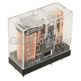
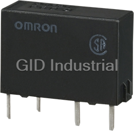
OMRON G2R-1-S 24VDC
Description
Omron G2R-1-S 24VDC Relay. General Purpose | Plug-in Terminal
Part Number
G2R-1-S 24VDC
Price
Request Quote
Manufacturer
OMRON
Lead Time
Request Quote
Category
Relays
Specifications
Coil Current
21.6mA
Coil Power
530 mW
Coil Resistance
1.1K Ohms
Coil Type
Non Latching
Coil Voltage
24VDC
Contact Form
SPDT (1 Form C)
Contact Material
-
Contact Rating (Current)
10A
Features
-
Lead Free Status
Lead Free
Mounting Type
Socketable
Operate Time
15ms
Operating Temperature
-40°C ~ 70°C
Packaging
Bulk
Relay Type
General Purpose
Release Time
10ms
RoHS Status
RoHS Compliant
Switching Voltage
440VAC, 125VDC - Max
Termination Style
Plug In, QC - 0.187" (4.7mm)
Turn Off Voltage (Min)
3.6 VDC
Turn On Voltage (Max)
16.8 VDC
Datasheet

Extracted Text
General-purpose Relay G2RS-(S) Slim and Space-saving Power Plug-in Relay • Lockable test button models now available. Built-in mechanical operation indicator. Provided with nameplate. AC type is equipped with a coil-disconnection self- diagnostic function (LED type). High switching power (1-pole: 10 A). Environment-friendly (Cd, Pb free). Wide range of Sockets also available. RoHS Compliant. LR Model Number Structure ■ Model Number Legend G2R - - - (S) 12 34 56 7 1. Relay Function 5. Terminals Blank:General-purpose S: Plug-in 2. Number of Poles 6. Classification 1: 1 pole Blank:General-purpose 2: 2 poles N: LED indicator 3. Contact Form D: Diode ND: LED indicator and diode Blank:SPDT 4. Contact Type NI: LED indicator with test button Blank:Single NDI: LED indicator and diode with test button 7. Rated Coil Voltage Ordering Information ■ List of Models Classification Enclosure Coil ratings Contact form/Model rating SPDT DPDT Plug-in terminal General-purpose Unsealed AC/DC G2R-1-S G2R-2-S LED indicator G2R-1-SN G2R-2-SN LED indicator with test button G2R-1-SNI G2R-2-SNI Diode DC G2R-1-SD G2R-2-SD LED indicator and diode G2R-1-SND G2R-2-SND LED indicator and diode with test button G2R-1-SNDI G2R-2-SNDI Note: When ordering, add the rated coil voltage and "(S)" to the model number. Rated coil voltages are given in the coil ratings table. Example: G2R-1-S DC12 (S) New model Rated coil voltage General-purpose Relay G2RS-(S) 267 ■ Accessories (Order Separately) Connecting Sockets Applicable Relay model Track/surface-mounting Socket Back-mounting Socket Screwless clamp terminal Screw terminal Terminals Model (See note.) 1 pole P2RF-05-S PCB terminals P2R-05P, P2R-057P P2RF-05-E G2R-1-S(N)(D)(ND)(NI)(NDI) + Solder terminals P2R-05A P2RF-05 P2CM-S 2 poles P2RF-08-S PCB terminals P2R-08P, P2R-087P P2RF-08-E G2R-2-S(N)(D)(ND)(NI)(NDI) + Solder terminals P2R-08A P2RF-08 P2CM-S Note: 1. Use of P2CM Clips are optional. However, use of the P2CM Clip & Release Lever is recommended to ensure stable mounting. 2. “-E” models are of finger-safe product construction. Round terminals cannot be used. Use Y-shaped terminals. Accessories for Screwless Clamp Terminal Socket (Option) Name Model Clip & Release Lever P2CM-S Nameplate R99-11 Nameplate for MY Socket Bridge P2RM-SR (for AC), P2RM-SB (for DC) Mounting Tracks Applicable Socket Description Model Mounting track and accessories Mounting track 50 cm (l) x 7.3 mm (t) PFP-50N 1 m (l) x 7.3 mm (t) PFP-100N 1 m (l) x 16 mm (t) PFP-100N2 End plate PFP-M Spacer PFP-S Mounting plate* Back-connecting Sockets P2R-P *Used to mount several P2R-05A and P2R-08A Connecting Sockets side by side. Specifications ■ Coil Ratings Rated voltage Rated current* Coil Coil inductance (H) Must Must Max. Power resistance* (ref. value) operate release voltage consumption voltage voltage (approx.) 50 Hz 60 Hz Armature Armature % of rated voltage OFF ON AC 24 V 43.5 mA 37.4 mA 253 Ω 0.81 1.55 80% max. 30% min. 110% 0.9 VA at 60 Hz 110 V 9.5 mA 8.2 mA 5,566 Ω 13.33 26.83 120 V 8.6 mA 7.5 mA 7,286 Ω 16.13 32.46 230 V 4.4 mA 3.8 mA 27,172 Ω 72.68 143.90 240 V 3.7 mA 3.2 mA 30,360 Ω 90.58 182.34 Rated voltage Rated current* Coil Coil inductance (H) Must Must Max. Power resistance* (ref. value) operate release voltage consumption voltage voltage (approx.) Armature Armature % of rated voltage OFF ON DC 6 V 87.0 mA 69 Ω 0.25 0.48 70% max. 15% min. 110% 0.53 W 12 V 43.2 mA 278 Ω 0.98 2.35 24 V 21.6 mA 1,113 Ω 3.60 8.25 48 V 11.4 mA 4,220 Ω 15.2 29.82 * The rated current and coil resistance are measured at a coil temperature of 23°C with tolerances of ±10%. 268 General-purpose Relay G2RS-(S) ■ Contact Ratings Number of poles 1 pole 2 poles Load Resistive load Inductive load Resistive load Inductive load (cosφ = 1) (cosφ = 0.4; L/R = 7 ms) (cosφ = 1) (cosφ = 0.4; L/R = 7 ms) Rated load 10 A at 250 VAC; 7.5 A at 250 VAC; 5 A at 250 VAC; 2 A at 250 VAC; 3 A at 10 A at 30 VDC 5 A at 30 VDC 5 A at 30 VDC 30 VDC Rated carry current 10 A 5 A Max. switching voltage 440 VAC, 125 VDC 380 VAC, 125 VDC Max. switching current 10 A 5 A Max. switching capacity 2,500 VA, 1,875 VA, 1,250 VA, 500 VA, 300 W 150 W 150 W 90 W Minimum permissible load 100 mA at 5 VDC 10 mA at 5 VDC -6 Note: P level: λ = 0.1 x 10 /operation 60 ■ Characteristics Item 1 pole 2 poles Contact resistance 100 mΩ max. Operate (set) time 15 ms max. Release (reset) time AC: 10 ms max.; DC: 5 ms max. AC: 15 ms max.; DC: 10 ms max. (w/built-in diode: 20 ms max.) (w/built-in diode: 20 ms max.) Max. operating Mechanical: 18,000 operations/hr frequency Electrical: 1,800 operations/hr (under rated load) Insulation resistance 1,000 MΩ min. (at 500 VDC) Dielectric strength 5,000 VAC, 50/60 Hz for 1 min between coil and 5,000 VAC, 50/60 Hz for 1 min between coil and contacts*; contacts*; 3,000 VAC, 50/60 Hz for 1 min between contacts of different polarity 1,000 VAC, 50/60 Hz for 1 min between contacts of 1,000 VAC, 50/60 Hz for 1 min between contacts of same polarity same polarity Vibration resistance Destruction: 10 to 55 to 10 Hz, 0.75 mm single amplitude (1.5 mm double amplitude) Malfunction: 10 to 55 to 10 Hz, 0.75 mm single amplitude (1.5 mm double amplitude) 2 Shock resistance Destruction: 1,000 m/s 2 2 Malfunction: 200 m/s when energized; 100 m/s when not energized Service life Mechanical: AC coil: 10,000,000 operations min.; DC coil: 20,000,000 operations min. (at 18,000 operations/hr) Electrical: 100,000 operations min. (at 1,800 operations/hr under rated load) (DC coil type) Ambient temperature Operating: –40°C to 70°C (with no icing or condensation) Ambient humidity Operating: 5% to 85% Weight Approx. 21 g Note: Values in the above table are the initial values. *4,000 VAC, 50/60 Hz for 1 minute when the P2R-05A or P2R-08A Socket is used. ■ Approved Standards UL Recognized (File No. E41643) - - Ambient Temp. = 40°C IEC/VDE (EN61810) Model Contact Coil ratings Contact ratings Cycles Contact Coil ratings Contact ratings Cycles form form 10 A, 30 VDC (resistive) 6, 12, 24, 48 VDC 5 A, 440 VAC (cosφ = 1.0) 3 3 G2R-1-S SPDT 10 A, 250 VAC (general use) 6 x 10 1 pole 24, 110, 120, 230, 10 A, 250 VAC (cosφ = 1.0) 100 x 10 TV-3 (NO contact only) 240 VAC 10 A, 30 VDC (0 ms) 5 to 110 VDC 5 to 240 VAC 5 A, 30 VDC (resistive) 6, 12, 24, 48 VDC 5 A, 250 VAC (cosφ =1.0) 3 3 G2R-2-S DPDT 5 A, 250 VAC (general use) 6 x 10 2 poles 24, 110, 120, 230, 100 x 10 5 A, 30 VDC (0 ms) TV-3 (NO contact only) 240 VAC CSA Certified (File No. LR31928) LR Model Contact Coil ratings Contact ratings Cycles Number Coil ratings Contact ratings Cycles form of poles 10 A, 30 VDC (resistive) 10 A, 250 VAC (general use) 3 G2R-1-S SPDT 10 A, 250 VAC (general use) 6 x 10 5 to 110 VDC 7.5 A, 250 VAC (PF0.4) 3 1 pole 100 x 10 TV-3 (NO contact only) 5 to 240 VDC 10 A, 30 VDC (resistive) 5 to 110 VDC 5A, 30VDC (L/R=7ms) 5 to 240 VAC 5 A, 30 VDC (resistive) 3 G2R-2-S DPDT 5 A, 250 VAC (general use) 6 x 10 5 A, 250 VAC (general use) TV-3 (NO contact only) 5 to 110 VDC 2 A, 250 VAC (PF0.4) 3 2 poles 100 x 10 5 to 240 VDC 5 A, 30 VDC (resistive) 3A, 30VDC (L/R=7ms) General-purpose Relay G2RS-(S) 269 Engineering Data ■ Maximum Switching Capacity Plug-in Relays G2R-1-S G2R-2-S 100 100 AC inductive load AC resistive (cosφ = 0.4) load AC inductive load AC resistive (cosφ = 0.4) 10 10 load DC resistive load DC resistive load DC inductive load 1 (L/R = 7 ms) 1 DC inductive load (L/R = 7 ms) 0.1 0.1 1 10 100 1000 1 10 100 1000 Switching voltage (V) Switching voltage (V) ■ Electrical Service Life Plug-in Relays G2R-1-S G2R-2-S 5,000 10,000 5,000 250-VAC/30-VDC 1,000 resistive load 1,000 500 250-VAC inductive load 30-VDC inductive load (L/R = 7ms) (cosφ = 0.4) 500 250-VAC/30-VDC resistive load 100 100 30-VDC inductive load (L/R = 7ms) 250-VAC 50 inductive load 50 (cosφ = 0.4) Switching current (A) Switching current (A) Ambient Temperature vs. Maximum Coil Voltage DC coil AC coil Note: The maximum voltage refers to the maximum value in a varying range of operating power voltage, not a continuous voltage. Ambient temperature (°C) 270 General-purpose Relay G2RS-(S) Maximum voltage (%) 3 Switching current (A) Service LIfe (x10 operations) 3 Service Life (x10 operations) Switching current (A) DC24V Dimensions Unit: mm (inch) ■ Relays with Plug-in Terminals SPDT Relays Terminal Arrangement/Internal Connections G2R-1-S, G2R-1-SN, G2R-1-SNI (Bottom View) G2R-1-SD, G2R-1-SND, G2R-1-SNDI G2R-1-SD (DC) G2R-1-S 1 1 13 max. 29 (1.14) max. (0.51) 2 4 3 5 2 4 3 5 35.5 max. (1.40) G2R-1-SN, G2R-1-SNI (DC) G2R-1-SN, G2R-1-SNI (AC) 20 (0.79) 1 1 5 (0.20) 1(0.04) 0.5 4.75 2 4 3 4 5 5 2 3 (0.02) (0.19) 7.5 (0.29) G2R-1-SND, G2R-1-SNDI (DC) 5.2 5.2 (0.20) (0.20) 17.5 1 (0.69) 2 4 3 5 DPDT Relays G2R-2-S, G2R-2-SN, G2R-2-SNI Terminal Arrangement/Internal Connections G2R-2-SD, G2R-2-SND, G2R-2-SNDI (Bottom View) G2R-2-S G2R-2-SD (DC) 1 234 1 234 29 max. 13 max. (1.14) (0.51) 8 765 8 765 35.5 max. (1.40) G2R-2-SN, G2R-2-SNI (AC) G2R-2-SN, G2R-2-SNI (DC) 20 (0.79) 1 234 1 234 6.2 2.5 8 765 0.5 8 7 6 5 (0.29) (0.10) (0.02) 2.4 (0.09) 7.4 8.9 (0.29) (0.35) G2R-2-SND, G2R-2-SNDI (DC) 5 (0.02) 5 (0.02) 1 234 19.4 (0.76) 8 765 General-purpose Relay G2RS-(S) 271 Track/Surface Mounting Sockets P2RF-05-S Terminal Arrangement 38.2 max. (1.50) (Top View) 36.5 max. (1.44) 11 14 32.6 (1.28) 27.6 (1.09) 12 22.6 (0.89) 24.5 (0.96) 35.4 92.0 max. (1.39) (3.62) A1 A2 Option (with ejector and Standard model label attached) 28.5 (1.12) 5.3 typical (0.21) 18.0 max. 32.6 (0.71) (1.28) Terminal Arrangement 38.2 max. (1.50) (Top View) P2RF-08-S 36.5 max.(1.44) 21 11 24 14 32.6 (1.28) 27.6 (1.09) 22 12 22.6 3.4 (0.13) typical (0.89) 24.5 (0.96) 92.0 max. (3.62) 35.4 (1.39) A1 A2 Option (with ejector Standard model and label attached) 28.6 (1.12) 5.3 typical (0.21) 18.0 max. 32.6 (1.28) (0.71) Accessories for P2RF-@-S Socket Bridge Clip and Release Lever 16.8 40.35 (0.66) (1.59) Note: The color of insulating coating indicates power type. 36 (1.42) Model Power Color P2RM-SR AC Red P2RM-SB DC Blue 272 General-purpose Relay G2RS-(S) Terminal Arrangement Mounting Holes P2RF-05-E P2RF-05-E (Top View) (for Surface Mounting) 2 (0.08) Five, M3.5×7 48 max. (1.89) 3.2 (0.13) 4 (11) dia. hole 39.5 2 (14) (1.55) 3 (12) 39.5±0.1 85.5 max. 35.5 (1.55 ±0.004) (3.37) (1.40) 3.5 (0.14) dia. hole 5 M3 or 3.5 (A1) 1 (0.14) dia. (A2) 5 11.5 (0.20) (0.45) 16.0 max. 61 max. (0.63) (2.40) Note: Pin numbers in parentheses apply to DIN standard. P2RF-08-E P2RF-08-E Terminal Arrangement Mounting Holes (Top View) (for Surface Mounting) 1.5 2 (0.08) (0.06) 48.0 max. Eight, M3×8 2 (0.08) 3 (0.12) (1.89) (21) 6 3 (11) 3.2 (0.13) 7 2 (12) (22) 39.5 dia. hole 54 (24) (14) (1.55) 35.5 85.5 max (3.37) (1.40) 39.5±0.1 (1.55±0.004) 3.5 (0.14) 8 (A1) dia. hole 1 M3 or 3.5 (0.14) (A2) 11.5 (0.45) dia. hole 5 (0.20) 61.0 max. (2.40) 16.0 (0.63) max. 2 (0.08) 7(0.28) P2RF-05 P2RF-05 Terminal Arrangement Mounting Holes Five, M3.5 x 8 (Top View) (for Surface Mounting) 4 (0.16) dia. holes 4.2 (0.16) dia. hole 71.5 max. 35.5 (2.81) (1.40) 30±0.05 (1.18±0.002) 4 19.5 (0.77) M3 or 3.2 (0.13) 19.5 max. (0.16) 30 max.(1.18) dia. hole (0.77) 54 max. (2.12) P2RF-08 P2RF-08 7 (0.28) 2 (0.08) Eight, M3.5 x 8 Terminal Arrangement Mounting Holes 4 (0.16) (Top View) (for Surface Mounting) dia. holes 4.2 (0.16) dia. hole 71.5 max. 35.5 (2.89) (1.40) 30±0.05 (1.18±0.002) 4 (0.16) 19.5 (0.77) 19.5 max. M3 or 3.2 (0.13) 30 max.(1.18) (0.77) dia. hole 54 max. (2.12) General-purpose Relay G2RS-(S) 273 Mounting Height of Relay with Track/Surface Mounting Sockets P2RF-@-E P2RF-@ 62.0 66.5 67.0 (2.44) (2.62) 70.5 (2.64) (2.77) P2RF-@-S 72.0 (2.83) 65.0 (2.56) 28.6 (1.12) 5.30 (0.21) typical Back-connecting Sockets Terminal Arrangement Mounting Holes 14.5 max. P2R-05P (1-pole) (Bottom View) Tolerance: ±0.1 4 (0.16) (0.57) 7 (0.27) 1(0.04) 4 (0.14) Five, 1.6 (0.06) 6 (0.24) dia. holes 4.5 (0.18) 35.5 max. 6 (0.24) 15 (1.40) (0.59) 4.5 (0.18) 1.2 (0.05) 4 (0.16) 15 (0.59) 3.5 (0.14) 4 (0.16) 1.5 (0.06) 5 (0.20) typical 7 (0.27) 4 (0.16) 7 (2.27) 36.5 max. (1.44) P2R-08P (2-pole) 14.5 max. Terminal Arrangement Mounting Holes 4 (0.16) (0.57) 0.3 (Bottom View) 7 (0.27) 7.5 Eight, 1.3 (0.05) (0.01) (0.29) dia. holes 5 (0.20) 5 (0.20) 35.5 max. 5 (0.20) 20 (1.40) (0.79) 1 (0.04) 5 (0.20) 20 2.8 (0.11) (0.79) 1.5 (0.06) 4.3 (0.17) typical 7.5 (0.29) Terminal plate thickness: 0.3 (0.01) 36.5 max. (1.44) 274 General-purpose Relay G2RS-(S) 5 (0.20) 14.5 max. P2R-05A (1-pole) 7 (0.28) 0.3 (0.57) 1.2 (0.05) (0.01) Terminal Arrangement 6.7 (0.26) (Bottom View) 3.8 (0.15) 35.5 max. 16.7 5 (0.20) (1.40) (0.66) Panel Cutout Five, 3 x 1.8-dia. holes 13.6±0.1 (0.12 x 0.07) (0.54±0.004) 6 (0.24) 36.5 max. Terminal plate thickness: 0.3 (1.44) 30.5±0.2 14.5 max. (1.20±0.008) 7 (0.28) 7 (0.28) (0.57) P2R-08A (2-pole) 0.3 1.2 (0.05) (0.01) 5 (0.20) 5 (0.20) 35.5 max. 20 (1.40) Recommended thickness of the panel is 1.6 to 2.0 mm (0.79) 2.6 (0.10) 2.8(0.11) 1.5 (0.06) Eight, 3 x 1.2 (0.12 x 0.05)dia. holes 7.5 (0.30) Terminal plate thickness: 0.3 36.5 max. (1.44) P2R-057P 14 max. (0.55) Terminal Arrangement Mounting Holes 16.4 (0.65) (Bottom View) 4±0.1 0.7 (0.03) 10.4 1(0.04) 8.7 (0.16±0.004) (0.41) Five, 1.6 (0.06) (0.34) dia. holes 37 max. 29.6 6±0.1(0.24±0.004) (1.46) (1.17) 4.5±0.1 15±0.1(0.59±0.004) (0.18±0.004) 7.4 (0.29) 4±0.1 (0.16±0.004) 8.7 5 (0.20) (0.34) 7±0.1(0.27±0.004) 41 max. (1.61) 14 max. (0.55) 16.4(0.65) Terminal Arrangement Mounting Holes P2R-087P (Bottom View) 1 (0.04) 10.4 7.5 7.5 (0.30) Eight, 1.3 (0.05) (0.41) (0.30) dia. holes 37 max. 29.1 (1.46) 5 (0.20) (1.15) 5 (0.20) 20 (0.79) 7.4 (0.29) 8.9 (0.35) 8.1(0.32) typical 41 max. (1.61) General-purpose Relay G2RS-(S) 275 Mounting Height of Relay with Back-connecting Sockets G2R-@P G2R-@A G2R-@7P G2R Relay G2R Relay 47.5 38.0 44.5 (1.87) (1.50) P2R-_A P2R-_P (1.75) Socket Socket Mounting Tracks PFP-100N, PFP-50N PFP-100N2 16 (0.63) 7.3±0.15 (0.29±0.006) 4.5 4.5 (0.18) (0.18) 24 27 29.2 35±0.3 (0.94) (1.06) 35±0.3 27±0.15 (1.15) (1.38±0.01) 15 25 25 25 25 25 25 15 (0.59) 25 (0.98) 1 (0.04) 1.5 (0.06) 15 (0.59) 25 (0.98) 15(0.59) 1 10 10 (0.39) 10 10 (0.39) or 5 (0.20) 1,000 1,000 (39.37) or 500 (19.68) (39.37) It is recommended to use a panel 1.6 to 2.0 mm thick. End Plate Spacer 16 (0.63) 10 (0.39) PFP-M 5 (0.20) 12 (0.47) PFP-S 6.2 (0.24) 1.8 (0.07) 1 (0.04) 35.5 50 35.3 34.8 1.8 (1.40) (1.39) 44.3 (1.37) (1.97) (0.07) (1.74) 11.5 1.3 (0.05) (0.45) 10 (0.39) M4 x 8 pan 4.8 (0.19) 16.5 (0.65) head screw Precautions Precautions for P2RF-@-S Connection !CAUTION Do not use the test button for any purpose other than testing. Be • Do not move the screwdriver up, down, or from side to side while it sure not to touch the test button accidentally as this will turn the is inserted in the hole. Doing so may cause damage to internal contacts ON. Before using the test button, confirm that circuits, the components (e.g., deformation of the clamp spring or cracks in the load, and any other connected item will operate safely. housing) or cause deterioration of insulation. Do not insert the screwdriver at an angle. Doing so may break the !CAUTION side of the socket and result in a short-circuit. Check that the test button is released before turning ON relay cir- cuits. !CAUTION If the test button is pulled out too forcefully, it may bypass the mo- mentary testing position and go straight into the locked position. !CAUTION Use an insulated tool when you operate the test button. 276 General-purpose Relay G2RS-(S) MEMO General-purpose Relay G2RS-(S) All sales are subject to Omron Electronic Components LLC standard terms and conditions of sale, which can be found at http://www.components.omron.com/components/web/webfiles.nsf/sales_terms.html ALL DIMENSIONS SHOWN ARE IN MILLIMETERS. To convert millimeters into inches, multiply by 0.03937. To convert grams into ounces, multiply by 0.03527. OMRON ON-LINE OMRON ELECTRONIC COMPONENTS LLC Global - http://www.omron.com 55 E. Commerce Drive, Suite B USA - http://www.components.omron.com Schaumburg, IL 60173 847-882-2288 Cat. No. X301-E-1b 09/11 Specifications subject to change without notice Printed in USA General-purpose Relay G2RS-(S)
Frequently asked questions
How does Industrial Trading differ from its competitors?

Is there a warranty for the G2R-1-S 24VDC?
Which carrier will Industrial Trading use to ship my parts?
Can I buy parts from Industrial Trading if I am outside the USA?
Which payment methods does Industrial Trading accept?
Why buy from GID?

Quality
We are industry veterans who take pride in our work

Protection
Avoid the dangers of risky trading in the gray market

Access
Our network of suppliers is ready and at your disposal

Savings
Maintain legacy systems to prevent costly downtime

Speed
Time is of the essence, and we are respectful of yours
Related Products
Omron 3G2C7CPU84E Relay-C20 PNP/RELAY,DC PS(EXP)
Omron G2R-1112S-FD-V- Relay - 24VDC Relay
Omron G3NA-220B-UTU DC5-24 Relay - SOLID STATE RELAY/TUV MARKINGS
Omron G6D-1A-ASI-DC24 Relays - Power PCB Relay, 5 A; Standard; Socket Mount; SPST-NO; 2880 Ohms;...

OMRON MK2P-S-250VAC Relay - 250VAC/28VDC 10A Res 250VAC 7A Gen 8 Pin Relay
Request a Quote

The quote request has been received
Close

Facing challenges or have inquiries? Feel free to contact us!
Call Us +1-469-283-2440
What they say about us
FANTASTIC RESOURCE
One of our top priorities is maintaining our business with precision, and we are constantly looking for affiliates that can help us achieve our goal. With the aid of GID Industrial, our obsolete product management has never been more efficient. They have been a great resource to our company, and have quickly become a go-to supplier on our list!
Bucher Emhart Glass
EXCELLENT SERVICE
With our strict fundamentals and high expectations, we were surprised when we came across GID Industrial and their competitive pricing. When we approached them with our issue, they were incredibly confident in being able to provide us with a seamless solution at the best price for us. GID Industrial quickly understood our needs and provided us with excellent service, as well as fully tested product to ensure what we received would be the right fit for our company.
Fuji
HARD TO FIND A BETTER PROVIDER
Our company provides services to aid in the manufacture of technological products, such as semiconductors and flat panel displays, and often searching for distributors of obsolete product we require can waste time and money. Finding GID Industrial proved to be a great asset to our company, with cost effective solutions and superior knowledge on all of their materials, it’d be hard to find a better provider of obsolete or hard to find products.
Applied Materials
CONSISTENTLY DELIVERS QUALITY SOLUTIONS
Over the years, the equipment used in our company becomes discontinued, but they’re still of great use to us and our customers. Once these products are no longer available through the manufacturer, finding a reliable, quick supplier is a necessity, and luckily for us, GID Industrial has provided the most trustworthy, quality solutions to our obsolete component needs.
Nidec Vamco
TERRIFIC RESOURCE
This company has been a terrific help to us (I work for Trican Well Service) in sourcing the Micron Ram Memory we needed for our Siemens computers. Great service! And great pricing! I know when the product is shipping and when it will arrive, all the way through the ordering process.
Trican Well Service
GO TO SOURCE
When I can't find an obsolete part, I first call GID and they'll come up with my parts every time. Great customer service and follow up as well. Scott emails me from time to time to touch base and see if we're having trouble finding something.....which is often with our 25 yr old equipment.
ConAgra Foods