

 Manufacturers
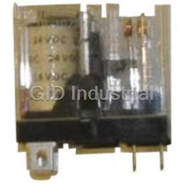
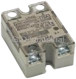
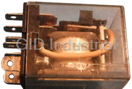
OMRON G6D-1A-ASI-DC24
Description
Omron G6D-1A-ASI-DC24 Relays - Power PCB Relay, 5 A; Standard; Socket Mount; SPST-NO; 2880 Ohms; 200 mW (Approx.)
Part Number
G6D-1A-ASI-DC24
Price
Request Quote
Manufacturer
OMRON
Lead Time
Request Quote
Category
Relays
Specifications
Carry current
5 A
Contact material
Ag alloy
Max. operating current
5 A
Max. operating voltage
250 VAC, 30 VDC
Max. switching capacity
Resistive load (p.f. - 1): 1,250 VA, 150 W | Inductive load (p.f. - 0.40, L/R - 7 ms): 500 VA, 60 W
Min. permissible load
10 mA at 5 VDC
Rated load
Resistive load (p.f. - 1): 5 A at 250 VAC, 30 VDC | Inductive load (p.f. - 0.40, L/R - 7 ms): 2 A at 250 VAC, 30 VDC
Features
- Long service life: up to 300,000 operations with a 2 A, 250 VAC/30 VDC load.
- Optional mounting socket simplifies relay installation and servicing of finished equipment.
- Rated for D150 pilot duty by UL, CSA.
- Reduced board space ideal for high-density mounting (45% smaller than the surface area of G6B).
- RoHS Compliant.
- Sealed construction allows automatic soldering and cleaning.
- Slim package: measures 6.5 W x 17.5 L x 12.5 H mm
- Switches loads up to 5 A, 250 VAC/30 VDC.
Datasheet

Extracted Text
Power PCB Relay G6D-ASI • Reduced board space ideal for high-density mounting (45% smaller than the surface area of G6B). Slim package: measures 6.5 W x 17.5 L x 12.5 H mm Switches loads up to 5 A, 250 VAC/30 VDC. Sealed construction allows automatic soldering and cleaning. Long service life: up to 300,000 operations with a 2 A, 250 VAC/30 VDC load. Rated for D150 pilot duty by UL, CSA. Optional mounting socket simplifies relay installation and servicing of finished equipment. RCE RoHS Compliant. Ordering Information To Order: Select the part number and add the desired coil voltage rating, (e.g., G6D-1A-ASI-DC12). Type Contact form Terminal Construction Model Standard SPST-NO PCB Fully sealed G6D-1A-ASI ■ Accessories Connecting Socket Description Model PCB mount socket for G6D relay P6D-04P Specifications ■ Contact Data Load Resistive load (p.f. = 1) Inductive load (p.f. = 0.40, L/R = 7 ms) Rated load 5 A at 250 VAC, 30 VDC 2 A at 250 VAC, 30 VDC Contact material Ag alloy Carry current 5 A Max. operating voltage 250 VAC, 30 VDC Max. operating current 5 A Max. switching capacity 1,250 VA, 150 W 500 VA, 60 W Min. permissible load 10 mA at 5 VDC -6 Note: P level: λ = 0.1 x 10 /operation 60 Power PCB Relay G6D-ASI 145 ■ Coil Data Rated Rated Coil Pick-up Dropout Maximum Power voltage current resistance voltage voltage voltage consumption (VDC) (mA) (Ω) (mW) % of rated voltage 5 40 125 70% max. 10% min. 160% at 23°C Approx. 200 12 16.7 720 24 8.3 2,880 Note: 1. The rated current and coil resistance are measured at a coil temperature of 23°C (73°F) with a tolerance of ±10%. 2. Operating characteristics are measured at a coil temperature of 23°C (73°F). 3. The pick-up voltage is 75% or less of rated voltage if the relay is mounted upside down. ■ Characteristics Contact resistance 100 mΩ max. Operate time 10 ms max. Release time 5 ms max. Operating Mechanical 18,000 operations/hour frequency Electrical 1,800 operations/hour (under rated load) Insulation resistance 1,000 MΩ min. (at 500 VDC) Dielectric strength 3,000 VAC, 50/60 Hz for 1 minute between coil and contacts 750 VAC, 50/60 Hz for 1 minute between contacts of the same polarity Surge withstand voltage 6,000 V, 1.20 x 50 μs between coil and contacts Vibration Mechanical durability 10 to 55 Hz, 1.50 mm (0.06 in) double amplitude Malfunction durability 10 to 55 Hz, 1.50 mm (0.06 in) double amplitude 2 Shock Mechanical durability 1,000 m/s (approx. 100 G) 2 Malfunction durability 100 m/s (approx. 10 G) Ambient temperature Operating -25° to 70°C (-13° to 158°F) Humidity 5% to 85% RH Life expectancy Mechanical 20 million operations min. (at operating frequency of 18,000 operations/hour) Electrical 70,000 operations min. at rated loads (300,000 operations min for 2A at 250 VAC, 30 VDC, resistive load) Weight Approx. 3 g (0.10 oz) Note: Data shown are of initial value. ■ Characteristic Data Maximum Switching Capacity Life Expectancy Ambient Temperature vs. Maximum Coil Voltage 50 500 200 30 300 180 100 10 160 AC resistive load 250-VAC/30-VDC resistive load 5 50 140 3 30 DC resistive load 120 AC inductive 10 1 load DC inductive cosφ=0.4 load 100 250-VAC/30 VDC inductive load 5 0.5 (cosφ=0.4/ L/R=7 ms) 0.3 3 80 0.1 60 0 1 2 3 4 5 6 7 8 9 10 0 3 5 10 30 100 250 500 1,000 02330 40 50 60 70 8090 Switching current (A) Switching voltage (V) Ambient temperature (°C) Note: The maximum coil voltage is the maximum voltage that can be applied to the relay coil. 146 Power PCB Relay G6D-ASI Switching current (A) 4 Life Expectancy (x10 operations) Maximum coil voltage (%) Malfunctioning Shock Ambient Temperature vs. G6D-1A-ASI Pickup and Drop out Voltage G6D-1A-ASI Y 100 Operating voltage 1,000 Sample: G6D1A Recovery voltage Quantity: 5 800 80 600 X Z 400 max. 200 60 X min. 40 206 Z' X' max. Shock direction XX' X 20 Y Not energized min. Z Energized Y' Z' 2 Unit: m/s 0 Y' −40 −20 0 20 40 60 80 Coil terminals Measurement conditions: Impose a shock in the Ambient temperature (°C) ±X, ±Y, and ±Z directions three times each with the Relay energized to check the shock values that cause the Relay to malfunction. Dimensions Unit: mm Note: Orientation marks are indicated as follows: ■ Relays 6.5 max. G6D-1A-ASI Terminal Arrangement/ Mounting Holes 0.5 17.5 max. (6.4)* Internal Connections (Bottom View) (17.3)* (Bottom View) Tolerance: ±0.1 12.5 max. Four, 1.1-dia. (1.13) 2.54 (12.4)* holes (0.71) 3.5 1 57 0.5 0.8 0.3 5.08 2.54 7.62. 2.54 5.08 5.08 13 *Average value 15.24 ■ Socket 19.7 max. P6D-04P (19.5)* Mounting Holes (Bottom View) 6.9 max. (6.7)* Tolerance: ±0.1 Four, 1.1-dia. (2.18) 2.54 holes (0.86) 10.8 6+0.1 5.08 3.6 2.54 0.65 0.3 2.54 76.2 5.08 15.24 *Average value Power PCB Relay G6D-ASI 147 Pickup and Drop out voltage (ratio of rated voltage) (%) ■ Approvals • The rated values approved by each of the safety standards may be different from the performance characteristics individually defined in this catalog. UL Recognized (File No. E41515) - - Ambient Temp. = 40°C Model Number of poles Coil ratings Contact ratings Number of test operations G6D-1A-ASI 1 5 to 24 VDC 5 A, 250 VAC 6,000 5 A, 30 VDC CSA Certified (File No. LR31928) Model Number of poles Coil ratings Contact ratings Number of test operations G6D-1A-ASI 1 5 to 24 VDC 5 A, 250 VAC (General Use) 6,000 5 A, 30 VDC (Resistive) EN/TÜV Approval (Registration No. R50029064/EN61810-1) Model Number of poles Coil ratings Contact ratings Number of test operations G6D-1A-ASI 1 5, 12, 24 VDC 5 A, 250 VAC (cosφ=1.0) 70,000 5 A, 30 VDC (0 ms) Note: 1. The rated values approved by each of the safety standards (e.g., UL, CSA, TUV) may be different from the performance characteristics individually defined in this catalog. 2. In the interest of product improvement, specifications are subject to change. Precautions ■ Spacing Between Relays ■ Socket Mounting More than two relays can be closely mounted right side up as shown When mounting the relay, insert it into the socket as vertically as pos- in the illustration below. sible so that the relay terminals contact securely with the contact pins on the socket. 6.5 mm The P6D-04P socket is flux-resistant. Do not wash the socket with water. Remove the relay from the socket before soldering the socket to a PC board. Current flow: Mounting height 5 A max. More than two relays can be closely mounted upside down as shown in the illustration below. 18.5 mm max. 7.62 mm in the upside-down direction Current flow: 2 A max. 1.12 mm Note: The space between each relay required for heat radiation may vary with operating conditions. 148 Power PCB Relay G6D-ASI MEMO Power PCB Relay G6D-ASI All sales are subject to Omron Electronic Components LLC standard terms and conditions of sale, which can be found at http://www.components.omron.com/components/web/webfiles.nsf/sales_terms.html ALL DIMENSIONS SHOWN ARE IN MILLIMETERS. To convert millimeters into inches, multiply by 0.03937. To convert grams into ounces, multiply by 0.03527. OMRON ON-LINE OMRON ELECTRONIC COMPONENTS LLC Global - http://www.omron.com 55 E. Commerce Drive, Suite B USA - http://www.components.omron.com Schaumburg, IL 60173 847-882-2288 Cat. No. X301-E-1b 09/11 Specifications subject to change without notice Printed in USA Power PCB Relay G6D-ASI
Frequently asked questions
How does Industrial Trading differ from its competitors?

Is there a warranty for the G6D-1A-ASI-DC24?
Which carrier will Industrial Trading use to ship my parts?
Can I buy parts from Industrial Trading if I am outside the USA?
Which payment methods does Industrial Trading accept?
Why buy from GID?

Quality
We are industry veterans who take pride in our work

Protection
Avoid the dangers of risky trading in the gray market

Access
Our network of suppliers is ready and at your disposal

Savings
Maintain legacy systems to prevent costly downtime

Speed
Time is of the essence, and we are respectful of yours
Related Products
Omron 3G2C7CPU84E Relay-C20 PNP/RELAY,DC PS(EXP)
Omron G2R-1112S-FD-V- Relay - 24VDC Relay
Omron G2R-1-S 24VDC Relay. General Purpose | Plug-in Terminal
Omron G3NA-220B-UTU DC5-24 Relay - SOLID STATE RELAY/TUV MARKINGS

OMRON MK2P-S-250VAC Relay - 250VAC/28VDC 10A Res 250VAC 7A Gen 8 Pin Relay
Request a Quote

The quote request has been received
Close

Facing challenges or have inquiries? Feel free to contact us!
Call Us +1-469-283-2440
What they say about us
FANTASTIC RESOURCE
One of our top priorities is maintaining our business with precision, and we are constantly looking for affiliates that can help us achieve our goal. With the aid of GID Industrial, our obsolete product management has never been more efficient. They have been a great resource to our company, and have quickly become a go-to supplier on our list!
Bucher Emhart Glass
EXCELLENT SERVICE
With our strict fundamentals and high expectations, we were surprised when we came across GID Industrial and their competitive pricing. When we approached them with our issue, they were incredibly confident in being able to provide us with a seamless solution at the best price for us. GID Industrial quickly understood our needs and provided us with excellent service, as well as fully tested product to ensure what we received would be the right fit for our company.
Fuji
HARD TO FIND A BETTER PROVIDER
Our company provides services to aid in the manufacture of technological products, such as semiconductors and flat panel displays, and often searching for distributors of obsolete product we require can waste time and money. Finding GID Industrial proved to be a great asset to our company, with cost effective solutions and superior knowledge on all of their materials, it’d be hard to find a better provider of obsolete or hard to find products.
Applied Materials
CONSISTENTLY DELIVERS QUALITY SOLUTIONS
Over the years, the equipment used in our company becomes discontinued, but they’re still of great use to us and our customers. Once these products are no longer available through the manufacturer, finding a reliable, quick supplier is a necessity, and luckily for us, GID Industrial has provided the most trustworthy, quality solutions to our obsolete component needs.
Nidec Vamco
TERRIFIC RESOURCE
This company has been a terrific help to us (I work for Trican Well Service) in sourcing the Micron Ram Memory we needed for our Siemens computers. Great service! And great pricing! I know when the product is shipping and when it will arrive, all the way through the ordering process.
Trican Well Service
GO TO SOURCE
When I can't find an obsolete part, I first call GID and they'll come up with my parts every time. Great customer service and follow up as well. Scott emails me from time to time to touch base and see if we're having trouble finding something.....which is often with our 25 yr old equipment.
ConAgra Foods