

 Manufacturers
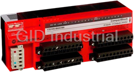
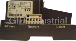
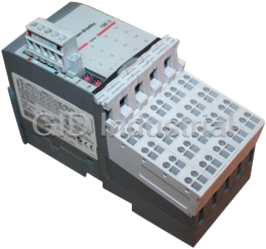
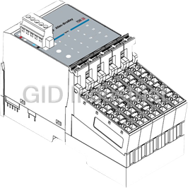
ALLEN-BRADLEY 1791DS-IB4XOW4
Description
Allen Bradley 1791DS-IB4XOW4 I/O Module - Devicenet Safety, 24V DC, 4 Inputs/4 Relay Outputs
Part Number
1791DS-IB4XOW4
Price
Request Quote
Manufacturer
ALLEN-BRADLEY
Lead Time
Request Quote
Category
I/O Module
Specifications
Current consumption
110 mA at 24V DC
Current, On-State Input, Min.
6 mA
Description
24V DC Input / Relay Output Module for DeviceNet Networks
Dimensions (HxWxD), Metric
95 x 170 x 83 mm
Electrical Service Life
100,000 operations min
Enclosure Protection
IP 20
Input Type
Current Sinking
Number of Inputs (single-channel)
4 safety
Number of Outputs
4 single-channel, safety relay
Number of Pulse Test Sources
4
Operating Shock
10 g
Operating Temperature
-10…55° C (14…131 °F)
Operating Voltage Range
20.4…26.4V DC (24V DC, -15…+10%)
Output Current Rating
2 A max. per contact
Output Type
Relay Output
Pulse Test Output Current
0.7 A per point
Relative Humidity
10…85% noncondensing
Vibration
5 g at 10…500 Hz
Voltage, Off-State Input, Max.
11V DC
Voltage, On-State Input, Min.
5V DC
Features
- Additional standard solid-state outputs that can be configured as pulse test sources, outputs for standard PLC control, 24V DC sources, or for muting lamp control and monitoring
- Certified by TÃœV for Functional Safety up to SIL 3 according to IEC 61508, and Category 4, PLe according to ISO 13849-1
- Compatible with Guardmaster and similar safety devices
- DIN Rail mounting for easy installation
- EDS (RSNetWorx for DeviceNet) or RSLogix 5000 profile configuration
- I/O point-level and other detailed fault diagnostics are available to the PLC or HMI, with the self testing inputs and outputs
- Supports both standard and safety control
- Supports single and dual channel devices on inputs and outputs
- TÃœV Certified as a system with GuardLogix and SmartGuard 600 controllers
Datasheet

Extracted Text
CompactBlock I/O CompactBlock LDX I/O SELECTION GUIDE 1790 SERIES 1791 SERIES Table of Contents Preface About This Selection Guide . . . . . . . . . . . . . . . . . . . . . . . . . . . . . . 5 Additional Resources. . . . . . . . . . . . . . . . . . . . . . . . . . . . . . . . . . . 5 Chapter 1 IP 20 Block I/O Overview Introduction . . . . . . . . . . . . . . . . . . . . . . . . . . . . . . . . . . . . . . . . . 7 General Features. . . . . . . . . . . . . . . . . . . . . . . . . . . . . . . . . . . . . . 8 Space-efficient. . . . . . . . . . . . . . . . . . . . . . . . . . . . . . . . . . . . . 8 Cost-effective . . . . . . . . . . . . . . . . . . . . . . . . . . . . . . . . . . . . . 8 Meets Industrial Standards . . . . . . . . . . . . . . . . . . . . . . . . . . . . 8 Allows Flexibility in I/O Selection . . . . . . . . . . . . . . . . . . . . . . 8 Easy to Install and Configure . . . . . . . . . . . . . . . . . . . . . . . . . . 8 Offers Built-in Network Connectivity . . . . . . . . . . . . . . . . . . . . 9 Supports Localized Control (CompactBlock I/O system only) . . 9 Easy to Maintain . . . . . . . . . . . . . . . . . . . . . . . . . . . . . . . . . . . 9 Product-specific Features. . . . . . . . . . . . . . . . . . . . . . . . . . . . . . . 11 CompactBlock LDX I/O System (1790D/1790P) . . . . . . . . . . . 11 CompactBlock I/O System (1791D/1791P/1791R) . . . . . . . . . . 12 Feature Comparison . . . . . . . . . . . . . . . . . . . . . . . . . . . . . . . . . . 13 Product Specifications for CompactBlock LDX I/O . . . . . . . . . . . . 14 Product Specifications for CompactBlock I/O Modules . . . . . . . . 18 Chapter 2 Specify a 1790 CompactBlock LDX What This Chapter Contains . . . . . . . . . . . . . . . . . . . . . . . . . . . . 23 Step 1: Select a Communication Network . . . . . . . . . . . . . . . . . . . 24 I/O System CompactBlock LDX I/O on the DeviceNet Network . . . . . . . . 24 CompactBlock LDX I/O on the PROFIBUS DP Network . . . . . 25 Step 2: Select Base and Expansion Modules . . . . . . . . . . . . . . . . . 26 Possible Configurations for CompactBlock LDX I/O on the DeviceNet Network . . . . . . . . . . . . . . . . . . . . . . . . . . . . . 26 Possible Configurations for CompactBlock LDX I/O on the PROFIBUS DP Network . . . . . . . . . . . . . . . . . . . . . . . . . . 27 Termination Type . . . . . . . . . . . . . . . . . . . . . . . . . . . . . . . . . 27 CompactBlock LDX I/O Base and Expansion Modules . . . . . . 29 Step 3: Select Optional Accessories . . . . . . . . . . . . . . . . . . . . . . . 30 Chapter 3 Specify a CompactBlock I/O What This Chapter Contains . . . . . . . . . . . . . . . . . . . . . . . . . . . . 31 Step 1: Select a Communication Network . . . . . . . . . . . . . . . . . . . 32 System CompactBlock I/O Modules on the DeviceNet Network . . . . . 32 CompactBlock I/O Modules on the PROFIBUS DP Network . . 36 CompactBlock I/O Modules on Remote I/O . . . . . . . . . . . . . . 37 Step 2: Select Base and Expansion Modules . . . . . . . . . . . . . . . . . 38 Possible Configurations for CompactBlock I/O Modules on DeviceNet, PROFIBUS DP, and Remote I/O Networks. . . . 38 Termination Type . . . . . . . . . . . . . . . . . . . . . . . . . . . . . . . . . 38 CompactBlock I/O Base and Expansion Modules . . . . . . . . . . 39 Step 3: Select Optional Accessories . . . . . . . . . . . . . . . . . . . . . . . 40 3 Publication 1790-SG001B-EN-P - March 2009 Table of Contents 4 Chapter 4 Network Specifications What This Chapter Contains . . . . . . . . . . . . . . . . . . . . . . . . . . . . 41 DeviceNet Network. . . . . . . . . . . . . . . . . . . . . . . . . . . . . . . . . . . 41 DeviceNet Communication. . . . . . . . . . . . . . . . . . . . . . . . . . . 41 Software and EDS File Requirements . . . . . . . . . . . . . . . . . . . 42 Power Supply Requirements . . . . . . . . . . . . . . . . . . . . . . . . . 42 PROFIBUS DP Network. . . . . . . . . . . . . . . . . . . . . . . . . . . . . . . . 43 PROFIBUS DP Communication . . . . . . . . . . . . . . . . . . . . . . . 43 System Configuration and Device Types. . . . . . . . . . . . . . . . . 44 Operating Modes and System Status . . . . . . . . . . . . . . . . . . . . 45 Cyclic Data Transmission . . . . . . . . . . . . . . . . . . . . . . . . . . . . 46 Configuration and GSD File Requirements . . . . . . . . . . . . . . . 47 Base Module to Expansion Interface. . . . . . . . . . . . . . . . . . . . 47 Power the Module. . . . . . . . . . . . . . . . . . . . . . . . . . . . . . . . . 47 Remote I/O (1791 CompactBlock I/O only) . . . . . . . . . . . . . . . . . . . . . . . . . . 48 Remote I/O Module Communication . . . . . . . . . . . . . . . . . . . 48 Power Supply Requirements . . . . . . . . . . . . . . . . . . . . . . . . . 50 Base Module to Expansion Interface. . . . . . . . . . . . . . . . . . . . 50 Power the Module. . . . . . . . . . . . . . . . . . . . . . . . . . . . . . . . . 50 Publication 1790-SG001B-EN-P - March 2009 Preface This publication aims to guide you through the selection process of About This Selection Guide Rockwell Automation in-cabinet block I/O products, namely CompactBlock LDX I/O and CompactBlock I/O, for your control applications. The publications listed in this table contain more information on Additional Resources CompactBlock LDX I/O modules. Related Publications for CompactBlock LDX I/O Modules Pub. Title Pub. Number 1790 CompactBlock LDX I/O Product Profile 1790-PP002 CompactBlock LDX Analog Modules User Manual 1790-UM001 CompactBlock LDX I/O for DeviceNet Technical Data 1790D-TD001 CompactBlock LDX I/O for PROFIBUS DP Technical Data 1790P-TD001 CompactBlock LDX RTD/Resistance Input Module User Manual 1790-UM002 CompactBlock LDX I/O Thermocouple Modules User Manual 1790-UM003 DeviceNet Analog Base D-Shell CompactBlock LDX I/O Installation 1790-IN004 Instructions DeviceNet Analog Base Terminal Block CompactBlock LDX I/O 1790-IN002 Installation Instructions DeviceNet Digital Base D-Shell Block CompactBlock LDX I/O 1790-IN007 Installation Instructions DeviceNet Digital Base D-shell Block CompactBlock LDX I/O Series B 1790-IN013 Installation Instructions DeviceNet Digital Base Terminal Block CompactBlock LDX I/O Series A 1790-IN006 Installation Instructions DeviceNet Digital Base Terminal Block CompactBlock LDX I/O Series B 1790-IN012 Installation Instructions Digital Expansion Terminal Block CompactBlock LDX I/O Installation 1790-IN005 Instructions Profibus DP Digital Base Terminal Block CompactBlock LDX I/O 1790-IN009 Installation Instructions 5 Publication 1790-SG001B-EN-P - March 2009 6 The publications listed in this table contain more information on CompactBlock I/O modules. Related Publications for CompactBlock I/O Modules Pub. Title Pub. Number 1791D CompactBlock I/O Product Profile 1791D-PP002 CompactBlock I/O for DeviceNet Technical Data 1791D-TD001 CompactBlock I/O for Profibus DP Technical Data 1791P-TD001 CompactBlock I/O on Remote I/O Technical Data 1791R-TD001 CompactBlock Distributed I/O on PROFIBUS DP Series D Installation 1791P-IN002 Instructions CompactBlock Distributed I/O on Remote I/O Series D Installation 1791R-IN002 Instructions CompactBlock I/O Analog Combination Input/Output Expansion Module 1791D-IN002 Installation Instructions CompactBlock I/O for DeviceNet Modules Series D Installation 1791D-IN003 Instructions CompactBlock Distributed I/O on Remote I/O Installation Instructions 1791R-IN001 You can view or download publications at http://literature.rockwellautomation.com. To order paper copies of technical documentation, contact your local Rockwell Automation distributor or sales representative. Publication 1790-SG001B-EN-P - March 2009 Chapter 1 IP 20 Block I/O Overview Rockwell Automation offers a wide selection of distributed I/O Introduction products for use in your control system. Distributed I/O can be mounted in-cabinet (IP 20) requiring an enclosure for protection from the environment, or as an On-Machine configuration (IP 67) not requiring an additional enclosure. Both in-cabinet and On-Machine distributed I/O types are offered in modular and block I/O styles. Modular I/O is a system of interface cards and communication adapters that interface directly with the sensors and actuators of the machine or process, and communicate their status to the controller via a communication network. It allows the system designer to mix and match I/O interfaces and communication adapters. Block I/O is a complete assembly of sensor and actuator interface points including a network adapter. This publication will guide you in the selection of in-cabinet block I/O products, namely CompactBlock I/O and CompactBlock LDX I/O. 7 Publication 1790-SG001B-EN-P - March 2009 8 Chapter 1: IP 20 Block I/O Overview Distributed I/O Product Matrix In-Cabinet On-Machine POINT I/O ArmorPoint I/O FLEX I/O CompactBlock I/O ArmorBlock MaXum I/O ArmorBlock I/O CompactBlock LDX I/O In-Cabinet On-Machine 44411 This section discusses the general features of Rockwell Automation General Features products in the in-cabinet block I/O category. Space-efficient A small form factor allows the distributed I/O products to be mounted into shallow enclosures and confined areas, thus saving cabinet space. Cost-effective The in-cabinet block I/O platform is a cost-effective solution for automation applications that exist in less-rigorous IP 20 environments. Publication 1790-SG001B-EN-P - March 2009 Block Modular Block Modular Chapter 1: IP 20 Block I/O Overview 9 The compact size of the products reduces your need for large enclosures, and the fact that the I/O is distributed means that extensive wiring is greatly reduced. Having single bus cabling also helps to ease maintenance work. Meets Industrial Standards All modules are tested to meet the most stringent industrial requirements to withstand electromagnetic (EM) interference, vibration, and shock. Allows Flexibility in I/O Selection A wide variety of base and expansion combinations lets you eliminate unnecessary I/O points. In addition, CompactBlock LDX I/O modules, including digital (24V dc, 120V ac, and relay), analog (current and voltage), and temperature (resistance temperature detector and thermocouple), are compatible with a variety of sensors. Easy to Install and Configure Modular electronic data sheet (EDS) or generic station description (GSD) files, rotary switches, and auto-baud rate detection provide easy commissioning. Offers Built-in Network Connectivity Built-in network adapters offer direct network connectivity. DeviceNet and PROFIBUS DP networks are supported on CompactBlock LDX I/ O and CompactBlock I/O systems. In addition, remote I/O is supported on the CompactBlock I/O system. Publication 1790-SG001B-EN-P - March 2009 10 Chapter 1: IP 20 Block I/O Overview Supports Localized Control (CompactBlock I/O system only) DeviceLogix smart-component technology on DeviceNet blocks enable localized, simple control functions for faster sense-to-actuation time. Easy to Maintain CompactBlock LDX I/O on the DeviceNet network has two termination types, namely D-shell connector and fixed-screw terminal block. The D-shell connector allows for simple, fast connections and easy maintainability. D-shell Connector 44417 Publication 1790-SG001B-EN-P - March 2009 6 7 4 5 0 1 2 3 6 7 4 5 0 1 2 3 Module Network Status Status Profibus DP Profibus DP Not Used GND IN0 IN4 IN5 IN7 IN15 IN12 IN3 IN9 IN2 IN10 IN1 IN13 IN6 IN14 VDC IN8 VDC IN11 GND Chapter 1: IP 20 Block I/O Overview 11 The CompactBlock I/O module contains a removable terminal block that allows for easy module replacement without rewiring. Removable terminal blocks on all modules are easy to maintain and help reduce your downtime. Removable Terminal Block Retaining Screw Retaining Screw 42979 Publication 1790-SG001B-EN-P - March 2009 12 Chapter 1: IP 20 Block I/O Overview This section discusses the features specific to the CompactBlock LDX Product-specific Features I/O and CompactBlock I/O systems. CompactBlock LDX I/O System (1790D/1790P) The CompactBlock LDX I/O system offers you a compact, cost-effective, and diverse distributed I/O solution for automation solutions. Offering 24V dc, 120V ac, relay, analog, and temperature modules, CompactBlock LDX I/O supports a wide breadth of field devices and is compatible on both DeviceNet and PROFIBUS DP networks. CompactBlock LDX I/O is especially suitable where low cost and confined space are coupled with less-stringent IP 20 environmental requirements. • CompactBlock LDX I/O has universal sink/source inputs that reduce the number of components to stock and allows flexibility of input types. • The digital base modules support up to 3 digital expansion modules and up to 80 points of I/O for the DeviceNet network and 64 points of I/O for the PROFIBUS DP network. • The analog base modules, both current and voltage, support two additional modules of up to 32 points of digital I/O. The resistance temperature detector (RTD) and thermocouple base modules do not support any expansion. • CompactBlock LDX I/O is compatible with a broad range of sensors (Type 3 for dc, Type 1 for ac). • The node address switches and auto-baud rate detection ease network commissioning. CompactBlock LDX I/O offers the leading, lowest-cost, device-level communication network, the DeviceNet network, to translate simple messages from the controller to the plant floor. • By using modular EDS files, it is easy to connect and configure CompactBlock LDX I/O. • Cyclic and change-of-state messaging increase network throughput, thus helping to increase productivity. • ODVA conformance improves the level of interoperability with other DeviceNet products. • CompactBlock LDX I/O for the DeviceNet network works with any available DeviceNet scanner. Publication 1790-SG001B-EN-P - March 2009 Chapter 1: IP 20 Block I/O Overview 13 CompactBlock LDX I/O is also available on another network, PROFIBUS DP. • Configure by using GSD files and any PROFIBUS DP configuration package. • CompactBlock LDX I/O for the PROFIBUS DP network works with any available PROFIBUS DP scanner. CompactBlock I/O System (1791D/1791P/1791R) The CompactBlock I/O system provides you with an easy-to-use, compact, and cost-effective distributed I/O solution. Handling 24V dc and analog applications on three networks, it can be distributed throughout your plant for applications such as material handling, conveyors, packaging, or where space is limited. CompactBlock I/O products provide higher performance and more benefits than other block I/O products. • IEC/NEMA Type 3+ inputs offer the widest range of compatible sensors. • 10…30V dc device power accommodates a broad range of applications. • Digital base modules range from 4…16 points per module, with each module containing a built-in network adapter. Each digital expansion module contains 16 points. • Analog expansion module provides 4 inputs and 2 outputs for either 0…20 mA, 4…20 mA, or 0…10V dc with each channel configurable by wiring. • Address switches and auto baud ease network commissioning. • Hardware Watchdog function secures state of I/O modules in case of a failure. • Output short-circuit protection protects outputs in case of accidental miswiring. • Having removable terminal blocks on all modules saves maintenance costs. The CompactBlock I/O system offers the leading, lowest-cost, device-level communication network, the DeviceNet network, to translate simple messages from the controller to the plant floor, giving you better diagnostic capabilities. • A single bus cable is used for reduced wiring costs. • Retention screws prevent cable disconnection from challenging environments. Publication 1790-SG001B-EN-P - March 2009 14 Chapter 1: IP 20 Block I/O Overview • Cyclic or change-of-state operation increases network bandwidth by sending I/O messages only when necessary. • ODVA conformance improves the level of interoperability with other DeviceNet products. • DeviceLogix smart component technology is included. This feature enables localized, simple control functions for faster sense-to-actuation times. The CompactBlock I/O system for the DeviceNet network works with any available DeviceNet scanner. CompactBlock I/O products are also available on remote I/O (RIO) and PROFIBUS DP networks. • RIO block configuration is accomplished via DIP switches, and no software is needed. • Configure by using GSD files and any PROFIBUS DP configuration package. • All base modules are compatible with all expansion modules (except for the 1791D-4BO module which is not expandable). This table provides a summarized comparison of the main features of Feature Comparison CompactBlock LDX I/O products with those of CompactBlock I/O products. Feature Comparison Features CompactBlock LDX I/O CompactBlock I/O Network • DeviceNet • DeviceNet • PROFIBUS • PROFIBUS • Remote I/O Base type • 16-channel • 16-channel • 32-channel Termination • Fixed terminal block • Removable terminal block • Removable D-shell Local control — DeviceLogix I/O type • Digital • Digital • Analog • Analog • Thermocouple • RTD Expansion Up to 3 expansion modules Up to 1 expansion module Publication 1790-SG001B-EN-P - March 2009 Chapter 1: IP 20 Block I/O Overview 15 This table contains specifications that are common to all of the 1790 Product Specifications for base and expansion modules. Individual module-connection sizes, CompactBlock LDX I/O word/bit definitions, schematics, wiring diagrams, and specifications can be found in their respective Technical Data publications as listed in Related Publications for CompactBlock LDX I/O Modules on page 5. Environmental Specifications Temperature, operating 0…55 °C (32…131 °F) IEC 60068-2-1 (Test Ad, Operating Cold), IEC 60068-2-2 (Test Bd, Operating Dry Heat), IEC 60068-2-14 (Test Nb, Operating Thermal Shock) Temperature, storage -40…85 °C (-40…185 °F) IEC 60068-2-1 (Test Ab, Unpackaged Nonoperating Cold), IEC 60068-2-2 (Test Bb, Unpackaged Nonoperating Dry Heat), IEC 60068-2-14 (Test Na, Unpackaged Nonoperating Thermal Shock) Relative humidity 5…90% non-condensing IEC 60068-2-30 (Test Db, Unpackaged Nonoperating) Operating altitude 2000m Vibration 5g @ 10…500 Hz IEC60068-2-6 (Test Fc, Operating) Shock, operating 10g IEC60068-2-27 Test Ea, (Unpackaged Shock) Shock, nonoperating 30g IEC60068-2-27 Test Ea, (Unpackaged Shock) Emissions Group 1, Class A CISPR 11 ESD immunity 8 kV air discharges IEC 61000-4-2 Radiated RF immunity 10V/m with 1 kHz sine-wave 80%AM from 80…1000 MHz 10V/m with 200Hz 50% Pulse 100%AM @ 900 MHz IEC 61000-4-3 EFT/B immunity ±1 kV @ 5 kHz on power ports ±2 kV @ 5 kHz on signal ports ±2 kV @ 5 kHz on communication ports IEC 61000-4-4 Surge transient immunity ±1 kV line-line (DM) and ±2 kV line-earth (CM) on power ports ±1 kV line-line (DM) and ±2 kV line-earth (CM) on signal ports ±2 kV line-earth (CM) on shielded ports IEC 61000-4-5 Conducted RF immunity 10V rms with 1 kHz sine-wave 80%AM from 150 kHz…80 MHz IEC 61000-4-6 Enclosure type rating IP 20 Publication 1790-SG001B-EN-P - March 2009 16 Chapter 1: IP 20 Block I/O Overview Environmental Specifications (Continued) Mounting DIN rail or panel mount Dimensions (HxWxD), 16ch DeviceNet version: approx. 52 x 104 x 42 mm (2.03 x 4.07 x 1.64 in.) 32ch DeviceNet version: 52 x 176 x 42 mm (2.03 x 6.93 x 1.64 in.) 16ch PROFIBUS version: 52 x 118.5 x 42 mm (2.03 x 4.62 x 1.64 in.) Weight, approx. 16ch version: 0.1 kg (0.3 lb) 32ch version: 0.3 kg (0.9 lb) DeviceNet Specifications for 1790D CompactBlock LDX I/O Network protocol I/O Slave messaging: - Poll command, Bit Strobe command, Cyclic command, COS command Network length, thick 500 m (1600 ft) @ 125 Kbps cable 200 m (600 ft) @ 250 Kbps 100 m (330 ft) @ 500 Kbps Network length, flat 420 m (1230 ft) @ 125 Kbps media 200 m (490 ft) @ 250 Kbps 75 m (245 ft) @ 500 Kbps Communication rate Auto-baud rate selection: 125, 250, 500 Kbps Indicators 1 red/green module status, 1 red/green network status Number of nodes 64 max - rotary-switch type node address setting General Specifications for 1790D CompactBlock LDX I/O Isolation voltage 50V dc (continuous), Reinforced Insulation Type Tested at 1250V dc for 60 s, I/O to system 2 Wire size 0.25…2.5 mm (22…14 AWG) solid or stranded copper wire rated at 75 °C or greater 1.2 mm (3/64 in.) insulation max (1) 2 - on signal ports Wiring category 2 - on power ports 2 - on communication ports Publication 1790-SG001B-EN-P - March 2009 Chapter 1: IP 20 Block I/O Overview 17 General Specifications for 1790D CompactBlock LDX I/O (Continued) (2) c-UL-us UL Listed Industrial Control Equipment, certified Product certifications for U.S. and Canada. (when product or packaging is marked) c-UL-us UL Listed for Class I, Division 2, Group A,B,C,D Hazardous Locations, certified for U.S. and Canada. CE European Union 89/336/EEC EMC Directive, compliant with: EN 50082-2; Industrial Immunity EN 61326; Meas./Control/Lab., Industrial Requirements EN 61000-6-2; Industrial Immunity EN 61000-6-4; Industrial Emissions European Union 73/23/EEC LVD, compliant with: EN61131-2; Programmable Controllers C-Tick Australian Radiocommunications Act, compliant with AS/NZS CISPR11; Industrial Emissions ODVA Open DeviceNet Vendor Association (ODVA) conformance tested to DeviceNet specifications (1) Use this wiring category information for planning conductor routing. Refer to Industrial Automation Wiring and Grounding Guidelines, publication 1770-4.1. (2) See the Product Certification link at http://www.ab.com for Declarations of Conformity, Certificates, and other certification details. PROFIBUS DP Specifications for 1790P CompactBlock LDX I/O Network protocol PROFIBUS-DP (EN50170) • Communication of the slave with a Class 1 master • Communication of the slave with a Class 2 master Implementation type DPC31 Station type Slave Freeze mode Supported Sync mode Supported Auto baud rate Supported (1) Fail safe mode Supported FMS support Not supported Redundancy Not supported Repeater control signal RS485 signal Publication 1790-SG001B-EN-P - March 2009 18 Chapter 1: IP 20 Block I/O Overview PROFIBUS DP Specifications for 1790P CompactBlock LDX I/O (Continued) Network length/ 1000 m (3280 ft) @ 9.6 kbps communication rate 1000 m (3280 ft) @ 19.2 kbps 1000 m (3280 ft) @ 45.45 kbps 1000 m (3280 ft) @ 93.75 kbps 1000 m (3280 ft) @ 187.5 kbps 400 m (1312 ft) @ 500 kbps 200 m (656 ft) @ 1.5 Mbps 100 m (328 ft) @ 3 Mbps 100 m (328 ft) @ 6 Mbps 100 m (328 ft) @ 12 Mbps Indicators 1 red/green module status 1 red/green network status Number of nodes 100 max - rotary-switch type node address setting (0-99) (1) Dependant upon the scanner module being used. For example, the SST scanner (catalog number SST-PFB-SLC) does not fully support Fail Safe mode as it only resets outputs to 0. You cannot define behavior such as Hold Last State or Fault Value with the SST scanner. General Specifications for 1790P CompactBlock LDX I/O Isolation Type test 1250V ac rms for 60 s between field power and the PROFIBUS DP network (I/O to logic) 2 Wire size 0.25…2.5 mm (22…14 AWG) solid or stranded copper wire rated at 75 °C or greater 1.2 mm (3/64 in.) insulation max (1) Wiring category 2 Product certifications c-UL-us UL Listed for Class I, Division 2 Group A,B,C,D (when product or Hazardous Locations, certified for U.S. and packaging is marked) Canada FM FM Approved Equipment (2) CE European Union 89/336/EEC EMC Directive, compliant with: EN 50082-2; Industrial Immunity EN 61326; Meas./Control/Lab., Industrial Requirements EN 61000-6-2; Industrial Immunity EN 61000-6-4; Industrial Emissions European Union 73/23/EEC LVD Directive, compliant with: EN 61131-2; Programmable Controllers 3 C-Tick Australian Radiocommunications Act, compliant with: AS/NZS 2064; Industrial Emissions (1) Use this wiring category information for planning conductor routing. Refer to Industrial Automation Wiring and Grounding Guidelines, publication 1770-4.1. (2) See the Product Certification link at http://www.ab.com for Declarations of Conformity, Certificates, and other certification details. Publication 1790-SG001B-EN-P - March 2009 Chapter 1: IP 20 Block I/O Overview 19 This table contains specifications that are common to all of the 1791 Product Specifications for base and expansion modules. Individual module-connection sizes, CompactBlock I/O Modules word/bit definitions, schematics, wiring diagrams, and specifications can be found in their respective Technical Data publications as listed in Related Publications for CompactBlock I/O Modules on page 6. Environmental Specifications Temperature, operating 0…60 °C (32…140 °F) IEC 60068-2-1 (Test Ad, Operating Cold), IEC 60068-2-2 (Test Bd, Operating Dry Heat), IEC 60068-2-14 (Test Nb, Operating Thermal Shock) Temperature, storage -40…85 °C (-40…185 °F) IEC 60068-2-1 (Test Ab, Unpackaged Nonoperating Cold), IEC 60068-2-2 (Test Bb, Unpackaged Nonoperating Dry Heat), IEC 60068-2-14 (Test Na, Unpackaged Nonoperating Thermal Shock) Relative humidity 5-95 % non-condensing IEC 60068-2-30 (Test Db, Unpackaged Nonoperating) Operating altitude 2000 m Vibration 5g @ 10…500 Hz IEC60068-2-6 (Test Fc, Operating) Shock, operating 30g Shock, nonoperating 50g IEC60068-2-27 Test Ea, (Unpackaged Shock) Emissions Group 1, Class A CISPR 11 Radiated RF immunity 10V/m with 1 kHz sine-wave 80%AM from 80…1000 MHz 10V/m with 200 Hz 50% Pulse 100%AM @ 900 MHz IEC 61000-4-3 EFT/B immunity ±1 kV @ 5 kHz on power ports ±2 kV @ 5 kHz on signal ports ±2 kV @ 5 kHz on communication ports IEC 61000-4-4 Surge transient immunity ±1 kV line-line (DM) and ±2 kV line-earth (CM) on power ports ±1 kV line-line (DM) and ±2 kV line-earth (CM) on signal ports ±2 kV line-earth (CM) on shielded ports IEC 61000-4-5 Conducted RF immunity 10V rms with 1 kHz sine-wave 80%AM from 150 kHz…80 MHz IEC 61000-4-6 Enclosure type rating IP 20 Mounting DIN rail or panel mount Publication 1790-SG001B-EN-P - March 2009 20 Chapter 1: IP 20 Block I/O Overview DeviceNet Specifications for 1791D CompactBlock I/O Network protocol I/O Slave messaging: - Poll command, Bit Strobe command, Cyclic command, COS command Network length, thick 500 m (1600 ft) @ 125 Kbps cable 200 m (600 ft) @ 250 Kbps 100 m (330 ft) @ 500 Kbps Network length, flat 420 m (1230 ft) @ 125 Kbps media 200 m (490 ft) @ 250 Kbps 75 m (245 ft) @ 500 Kbps Communication rate Auto-baud rate selection: 125, 250, 500 Kbps Indicators 1 red/green for module/network status, 1 green for logic status, 1 yellow for I/O status Number of nodes 64 max - rotary-switch type node address setting General Specifications for 1791D CompactBlock I/O Isolation voltage: I/O to DeviceNet 500V ac I/O group-to-group 500V ac I/O group-to-logic 500V ac DeviceNet power 11…25V dc (1) Wiring category 2 2 Wire size 2 mm (14 gauge) stranded maximum (3/64 in. insulation max) Product certifications c-UL-us UL Listed Industrial Control Equipment, certified (when product or for U.S. and Canada packaging is marked) c-UL-us UL Listed for Class I, Division 2, Group A,B,C,D Hazardous Locations, certified for U.S. and Canada. FM FM Approved Equipment (2) CE European Union 89/336/EEC EMC Directive, compliant with: EN 50082-2; Industrial Immunity EN 61326; Meas./Control/Lab., Industrial Requirements EN 61000-6-2; Industrial Immunity EN 61000-6-4; Industrial Emissions European Union 73/23/EEC LVD Directive, compliant with: EN 61131-2; Programmable Controllers Publication 1790-SG001B-EN-P - March 2009 Chapter 1: IP 20 Block I/O Overview 21 General Specifications for 1791D CompactBlock I/O (Continued) 3 Product certifications C-Tick Australian Radiocommunications Act, compliant (when product or with: packaging is marked) AS/NZS 2064; Industrial Emissions (continued) ODVA Open DeviceNet Vendor Association (ODVA) conformance tested to DeviceNet specifications (1) Use this wiring category information for planning conductor routing. Refer to Industrial Automation Wiring and Grounding Guidelines, publication 1770-4.1. (2) See the Product Certification link at http://www.ab.com for Declarations of Conformity, Certificates, and other certification details. PROFIBUS DP Specifications for 1791P CompactBlock I/O Network protocol PROFIBUS-DP (EN50170) • Communication of the slave with a Class 1 master • Communication of the slave with a Class 2 master Implementation type DPC31 Station type Slave Freeze mode Supported Sync mode Supported Auto baud rate Supported (1) Fail safe mode Supported FMS support Not supported Redundancy Not supported Network length/ 1000 m (3280 ft) @ 9.6 kbps communication rate 1000 m (3280 ft) @ 19.2 kbps 1000 m (3280 ft) @ 45.45 kbps 1000 m (3280 ft) @ 93.75 kbps 1000 m (3280 ft) @ 187.5 kbps 400 m (1312 ft) @ 500 kbps 200 m (656 ft) @ 1.5 Mbps 100 m (328 ft) @ 3 Mbps 100 m (328 ft) @ 6 Mbps 100 m (328 ft) @ 12 Mbps Indicators 1 red/orange/green module status 1 yellow network status Number of nodes 100 max - rotary-switch type node address setting (0-99) (1) Dependant upon the scanner module being used. For example, the SST scanner (catalog number SST-PFB-SLC) does not fully support Fail Safe mode as it only resets outputs to 0. You cannot define behavior such as Hold Last State or Fault Value with the SST scanner. Publication 1790-SG001B-EN-P - March 2009 22 Chapter 1: IP 20 Block I/O Overview General Specifications for 1791P CompactBlock I/O Isolation voltage Auxiliary I/O power to PROFIBUS: 500V ac I/O group-to-group: 500V ac I/O group-to-PROFIBUS: 500V ac PROFIBUS DP power 18…26.4V dc (1) Wiring category 2 2 Wire size 2 mm (14 gauge) stranded maximum (3/64 in. insulation max) Product certifications c-UL-us UL Listed Industrial Control Equipment, certified (when product is marked) for U.S. and Canada c-UL-us UL Listed for Class I, Division 2, Group A,B,C,D Hazardous Locations, certified for U.S. and Canada. (2) CE European Union 89/336/EEC EMC Directive, compliant with: EN 50081-2; Industrial Emissions EN 50082-2; Industrial Immunity EN 61326; Meas./Control/Lab., Industrial Requirements EN 61000-6-2; Industrial Immunity 3 C-Tick Australian Radiocommunications Act, compliant with: AS/NZS 2064; Industrial Emissions (1) Use this wiring category information for planning conductor routing. Refer to Industrial Automation Wiring and Grounding Guidelines, publication 1770-4.1. (2) See the Product Certification link at http://www.ab.com for Declarations of Conformity, Certificates, and other certification details. Publication 1790-SG001B-EN-P - March 2009 Chapter 1: IP 20 Block I/O Overview 23 Remote I/O Specifications for 1791R CompactBlock I/O Network protocol Remote I/O Network length/ 3048 m (10000 ft) max @ 57.6 kbps, communication rate 1524 m (5000 ft) max @ 115.2 kbps, 762 m (2500 ft) max @ 230.4 kbps Indicators 1 red/orange/green module status, 1 green comm status Number of nodes Processor-dependent. Refer to processor manual. General Specifications for 1791R CompactBlock I/O Isolation voltage Power supply to Remote I/O: 500V ac I/O group-to-Remote I/O: 500V ac I/O group-to-logic: 500V ac Remote I/O power 18…26.4V dc (1) Wiring category 2 2 Wire size 2 mm (14 gauge) stranded maximum (3/64 in. insulation max) Product certifications c-UL-us UL Listed Industrial Control Equipment, certified (when product is marked) for U.S. and Canada c-UL-us UL Listed for Class I, Division 2, Group A,B,C,D Hazardous Locations, certified for U.S. and Canada. (2) CE European Union 89/336/EEC EMC Directive, compliant with: EN 50081-2; Industrial Emissions EN 50082-2; Industrial Immunity EN 61326; Meas./Control/Lab., Industrial Requirements EN 61000-6-2; Industrial Immunity 3 C-Tick Australian Radiocommunications Act, compliant with: AS/NZS 2064; Industrial Emissions (1) Use this wiring category information for planning conductor routing. Refer to Industrial Automation Wiring and Grounding Guidelines, publication 1770-4.1. (2) See the Product Certification link at http://www.ab.com for Declarations of Conformity, Certificates, and other certification details. Publication 1790-SG001B-EN-P - March 2009 24 Chapter 1: IP 20 Block I/O Overview Publication 1790-SG001B-EN-P - March 2009 Chapter 2 Specify a 1790 CompactBlock LDX I/O System This chapter guides you in specifying a CompactBlock LDX I/O What This Chapter Contains system. Step 1: Select a Communication Network page 24 CompactBlock LDX I/O on the DeviceNet Network..... page 24 Step 2: Select Base and Expansion Modules page 26 Possible Configurations for CompactBlock LDX I/O on the PROFIBUS DP Network................................................. page 27 Possible Configurations for CompactBlock LDX I/O on the DeviceNet Network ....................................................... page 26 Step 3: Select Optional Accessories page 23 Publication 1790-SG001B-EN-P - March 2009 24 Chapter 2: Specify a 1790 CompactBlock LDX I/O System Using this table as a guide, select the communication network that is Step 1: Select a most suitable. This will determine the type of CompactBlock LDX I/O Communication Network products you will need. Select a Communication Network Application requirements Select this Select this type of network CompactBlock LDX I/O • Connections of low-level devices directly to plant-floor controllers DeviceNet 1790D-xxx • Data sent as needed • Diagnostics for improved data collection and fault detection • Less wiring and reduced start-up time than a traditional, hard-wired system • Connecting to an existing PROFIBUS DP network PROFIBUS DP 1790P-xxx CompactBlock LDX I/O on the DeviceNet Network This illustration shows how CompactBlock LDX I/O modules fit into a typical DeviceNet system. CompactBlock LDX I/O Modules in a DeviceNet System 1756 ControlLogix Modules 1747-SDN Scanner 1768 CompactLogix Modules 1784-PCD PCMCIA card Personal Computer with Configuration Software SLC Controller FLEX I/O Modules DTAM Micro Series 9000 DeviceView PowerFlex or DTAM Plus GV3000 Photoelectric FlexPac Hand-held Drive Module Drive Sensors 3000 Drive Computer 1305 Drive ArmorBlock I/O Modules Ezlink BASE UNIT CompactBlock LDX EXPANSION UNIT CompactBlock LDX EXPANSION UNIT CompactBlock LDX PULL PULL PULL PULL PULL PULL Bearing Monitor Motor Starter SMC Dialog RediSTATION with SMP-3 1336 PLUS Plus Module 1336 FORCE Interface Overload Relay 1790D CompactBlock LDX I/O Modules Drive Drive DeviceLink I/O with Limit Switch 44412 See Chapter 4 for DeviceNet network specifications. Publication 1790-SG001B-EN-P - March 2009 Chapter 2: Specify a 1790 CompactBlock LDX I/O System 25 CompactBlock LDX I/O on the PROFIBUS DP Network This illustration shows how CompactBlock LDX I/O fits into a typical PROFIBUS DP system. CompactBlock LDX I/O Modules in a PROFIBUS DP System PROFIBUS DP Scanner PROFIBUS DP 1756 ControlLogix Module or PLC-5 or other Scanner other Programmable Controller Programmable Controller Personal Computer with Configuration software SLC or other Controller FLEX I/O Modules HMI Transmitter Sensor HMI Field Device Sensor PowerFlex Drive POINT I/O Modules Interface CompactBlock LDX EXPANSION UNIT CompactBlock LDX EXPANSION UNIT CompactBlock LDX BASE UNIT PULL PULL PULL PULL PULL PULL 1791P CompactBlock I/O FlexArmor Modules 1790P CompactBlock LDX I/O Modules Modules 44413 See Chapter 4 for PROFIBUS DP network specifications. Publication 1790-SG001B-EN-P - March 2009 26 Chapter 2: Specify a 1790 CompactBlock LDX I/O System Determine the number of I/O inputs and outputs required and their Step 2: Select Base and mix. Expansion Modules Possible Configurations for CompactBlock LDX I/O on the DeviceNet Network Both digital and analog base modules support up to three expansion modules. Beginning with the base module, you can mount the modules either horizontally or vertically as shown in the figure. BASE UNIT CompactBlockLDX EXPANSION UNIT CompactBlockLDX EXPANSION UNIT CompactBlockLDX EXPANSION UNIT CompactBlockLDX PULL PULL PULL PULL PULL PULL PULL PULL RIGHT SIDE UP RIGHT SIDE UP RIGHT SIDE UP RIGHT SIDE UP BASE UNIT CompactBlockLDX PULL PULL The longer expansion cable (catalog number RIGHT SIDE UP 1790-15CMCBL) allows up to 7 cm (2.76 in.) of space between modules. UPSIDE DOWN EXPANSION UNIT CompactBlockLDX PULL PULL RIGHT SIDE UP Expansion Module 44416 Publication 1790-SG001B-EN-P - March 2009 EXPANSION UNIT CompactBlockLDX PULL PULL Chapter 2: Specify a 1790 CompactBlock LDX I/O System 27 Possible Configurations for CompactBlock LDX I/O on the PROFIBUS DP Network Digital and analog base modules support up to three or two expansion modules respectively. However, RTD and thermocouple base modules do not support expansion modules. Digital Base Module 1 or or Digital Expansion Modules 23 BASE UNIT CompactBlockLDX EXPANSION UNIT CompactBlockLDX EXPANSION UNIT CompactBlockLDX EXPANSION UNIT CompactBlockLDX PULL PULL PULL PULL PULL PULL PULL PULL Analog Base Module 1 or 2 Digital Expansion Modules BASE UNIT CompactBlockLDX EXPANSION UNIT CompactBlockLDX EXPANSION UNIT CompactBlockLDX PULL PULL PULL PULL PULL PULL RTD or Thermocouple Base Module CompactBlockLDX BASE UNIT PULL PULL Digital Expansion Modules 0 44414 Termination Type There are two termination types available, the D-shell connector and fixed-screw termination. The D-shell connector is available only for CompactBlock LDX I/O on the DeviceNet network. Publication 1790-SG001B-EN-P - March 2009 28 Chapter 2: Specify a 1790 CompactBlock LDX I/O System Termination Types for CompactBlock LDX I/O (1) Base Module with Screw Terminations Base Module with D-shell Connector (1) Expansion Module with Screw Terminations Expansion Module with D-shell Connector (1) Available only for CompactBlock LDX I/O on the DeviceNet network. 44420 Publication 1790-SG001B-EN-P - March 2009 1790D-T8BV8VX 1790D-8BV8VX Chapter 2: Specify a 1790 CompactBlock LDX I/O System 29 CompactBlock LDX I/O Base and Expansion Modules This table lists the catalog numbers for the CompactBlock LDX I/O base modules. CompactBlock LDX I/O Base Modules DeviceNet PROFIBUS DP I/O Mix D-shell Terminal Block Terminal Block 1790D-xxx 1790D-Txxx 1790P-Txxx Discrete I/O 8 input, 120V ac — 1790D-T8A0 — 8 universal in/8 source out 1790D-8BV8B 1790D-T8BV8B 1790P-T8BV8B 8 universal in/8 sink out 1790D-8BV8V 1790D-T8BV8V 1790P-T8BV8V 16 universal in 1790D-16BV0 1790D-T16BV0 — 16 universal in/16 sink out — 1790D-T16BV16V — 16 universal in/16 source out — 1790D-T16BV16B — 32 universal in — 1790D-T32BV0 — 6 output, 120V ac — 1790D-T0A6 — 6 relay output 1790D-0W6 1790D-T0W6 1790P-T0W6 16 sinking output 1790D-0V16 1790D-T0V16 — 16 sourcing output 1790D-0B16 1790D-T0B16 — 32 sinking output — 1790D-T0V32 — 32 sourcing output — 1790D-T0B32 — Analog I/O 4 input current 1790D-N4C0 1790D-TN4C0 1790P-TN4C0 4 input voltage 1790D-N4V0 1790D-TN4V0 — 4 input RTD 1790D-4R0 1790D-T4R0 1790P-T4R0 4 input thermocouple 1790D-4T0 1790D-T4T0 1790P-T4T0 2 output current 1790D-N0C2 1790D-TN0C2 1790P-TN0C2 2 output voltage 1790D-N0V2 1790D-TN0V2 — Publication 1790-SG001B-EN-P - March 2009 30 Chapter 2: Specify a 1790 CompactBlock LDX I/O System This table lists the catalog numbers for the CompactBlock LDX I/O expansion modules. CompactBlock LDX I/O Expansion Modules I/O Mix D-shell Terminal Block 1790-xxx 1790-Txxx 8 input, 120V ac — 1790-T8A0X 8 relay out 1790-0W8X 1790-T0W8X 8 univ in/8 sink out 1790-8BV8VX 1790-T8BV8VX 8 univ in/8 source out 1790-8BV8BX 1790-T8BV8BX 16 universal in 1790-16BV0X 1790-T16BV0X 8 output, 120V ac — 1790-T0A8X 16 sink out 1790-0V16X 1790-T0V16X 16 source out 1790-0B16X 1790-T0B16X For detailed specifications of the modules, refer to the respective Technical Data publications as listed in Related Publications for CompactBlock LDX I/O Modules on page 5. This table lists the optional components for CompactBlock LDX I/O Step 3: Select Optional modules. Accessories Optional Components for CompactBlock LDX I/O Optional Component Catalog No. LDX I/O replacement ribbon cable, 7 cm (2.76 in.), in lots of 5 1790-7CMCBL LDX I/O longer ribbon cable, 15 cm (5.90 in.), in lots of 5 1790-15CMBL Five-position open-style plug for the DeviceNet network 1799-DNETCON Five-position open-style plug/locking screws for the DeviceNet 1799-DNETSCON network DeviceNet five-position plug to five-pin micro male connector, 1799-DNC5MMS straight, in lots of five Publication 1790-SG001B-EN-P - March 2009 Chapter 3 Specify a CompactBlock I/O System This chapter guides you in specifying a CompactBlock I/O system. What This Chapter Contains Step 1: Select a Communication Network page 32 CompactBlock I/O Modules on the DeviceNet Network ... page 32 CompactBlock I/O Modules on the PROFIBUS DP Network page 36 CompactBlock I/O Modules on Remote I/O....................... page 37 Step 2: Select Base and Expansion Modules page 38 Possible Configurations for CompactBlock I/O Modules on DeviceNet, PROFIBUS DP, and Remote I/O Networks page 38 Step 3: Select Optional Accessories page 31 Publication 1790-SG001B-EN-P - March 2009 6 6 32 Chapter 3: Specify a CompactBlock I/O System Using this table as a guide, select the communication network that is Step 1: Select a most suitable. This will determine the type of CompactBlock I/O Communication Network products you will need. Select a Communication Network Application Requirements Network Select • Connections of low-level devices directly to plant-floor controllers, without DeviceNet 1790D-xxx interfacing them • Data sent as needed • More diagnostics for improved data collection and fault detection • Less wiring and reduced start-up time than a traditional, hard-wired system • Connecting to an existing PROFIBUS DP 5 m (16.4 ft) bus, 12 MB network PROFIBUS 1790P-xxx • Connecting to an existing Allen-Bradley remote I/O network Remote I/O 1790R-xxx CompactBlock I/O Modules on the DeviceNet Network This graphic shows how CompactBlock I/O modules fit into a typical DeviceNet system. CompactBlock I/O Modules in a DeviceNet System 1756 ControlLogix Modules 1747-SDN Scanner 1768 CompactLogix Modules 1784-PCD PCMCIA card Personal Computer with Configuration Software SLC Controller FLEX I/O Modules DTAM Micro Series 9000 DeviceView PowerFlex or DTAM Photoelectric GV3000 FlexPac Hand-held Drive Plus Module Sensors Drive 3000 Drive Computer 1305 Drive ArmorBlock I/O Modules Ezlink 0 123 4 5 7 0 123 4 5 7 Bearing CompactBlock I/O Monitor Motor Starter SMC Dialog RediSTATION with SMP-3 1336 PLUS Plus Module 1791D CompactBlock I/O Modules 1336 FORCE Interface Overload Relay Drive Drive DeviceLink I/O with Limit Switch 44423 See Chapter 4 for DeviceNet network specifications. Publication 1790-SG001B-EN-P - March 2009 Chapter 3: Specify a CompactBlock I/O System 33 In addition, CompactBlock I/O modules on the DeviceNet network have these features: • Input Filtering • Idle and Fault Mode Selection • DeviceLogix Functionality • Optional I/O Assemblies Input Filtering Input filtering limits the effect of voltage transients caused by contact bounce and/or electrical noise. If not filtered, voltage transients could produce false data. To configure an input filter, an input signal delay is set to turn off-to-on or on-to-off for nominal amounts of time. The mode and filter time is set through RSNetworx for DeviceNet software, or a similar configuration tool. Idle and Fault Mode Selection When the PLC, SLC, or PC-based programmable controller is in Program mode, the DeviceNet scanner puts the CompactBlock module in an idle state. If the DeviceNet scanner drops off the network, the module goes to a fault state. In both idle and fault states, the module resets its outputs by default. You can use RSNetworx for DeviceNet software or a similar configuration tool to change the default and set the module to save the last received outputs. Hold Last State (HLS) Fault HLS State Use Fault Value 0 Fault Apply 0 To Output Value 1 Apply 1 To Output Fault state can be set to HLS or use fault value. The fault value can be set to 0 or 1. The same logic applies for idle conditions. 42455 Publication 1790-SG001B-EN-P - March 2009 34 Chapter 3: Specify a CompactBlock I/O System DeviceLogix Functionality The CompactBlock I/O family also offers modules that have DeviceLogix capability, a local logic that provides you with the ability to control outputs and manage status information locally, within the device.DeviceLogix capability is configured through a function block editor that is accessed through RSNetW orx for DeviceNet software. This editor lets you create local logic by using boolean operators, such as AND and OR, set and reset latches, as well as a variety of timers and counters. User support for the editor can be found in the DeviceLogix Ladder Editor User Manual, publication ACIG-UM002, and online help. CompactBlock products that support DeviceLogix technology have some device-specific capabilities and capacities, which are identified in this table. Capability/Capacity CompactBlock I/O Modules Function blocks supported • Boolean - AND, OR, XOR, NOT, NAND, NOR, XNOR • Latches - RSL and SRL • Timers - PUL, OND, and OFD • Counters - UPC and UPD Number of function blocks 48 included in a configuration, max Function block processing time 1 ms/24 blocks 2 ms/48 blocks Network input bits 32 Network output bits 8 Available status bits • Explicit message connection • Polled connection • Change-of-state/cyclic connection • Network fault • Minor module fault • Polled connection fault • Polled connection idle • Change-of-state/cyclic connection fault Logic status indication • Logic disabled - none • Logic enabled - solid green • Local forces are applied and local logic is enabled - flashing green Optional I/O Assemblies The DeviceLogix-capable versions of CompactBlock I/O modules give you the ability to choose how much data the modules produce or consume over the DeviceNet network. Two new parameters have been added to the EDS files that let you select the amount of data that will be transmitted or received. Publication 1790-SG001B-EN-P - March 2009 Chapter 3: Specify a CompactBlock I/O System 35 Produced I/O Assembly These three options are for Produced Data: • Default assembly - Produces the device’s input data and any fault/status data the device has. • Input only assembly - Produces only the state of the device’s inputs. This lets those who do not make use of the Diagnostic bits reduce their network traffic. • DeviceLogix assembly - Produces all of the standard information from the Default assembly plus the data that is available as a result of invoking DeviceLogix technology. These new DeviceLogix data are available: – Logic Enabled bit - This bit is high when the DeviceLogix configuration is running on a device and has been enabled. This can be used, for example, in the PLC program or on a DeviceNet MMI to indicate the presence of local logic control. – Network Output bits - These bits are used in the DeviceLogix configuration to send information back over the network. For example, the output of any function block can be connected to a network output bit. – Hardware Output bits - The DeviceLogix configuration lets you locally control the state of hardware outputs. Therefore these bits are produced by the device so that the state of the outputs can be sent back to the network master. If an output in the device is not under DeviceLogix control, its status is still controlled by the normal consumed data. Please refer to the CompactBlock I/O for DeviceNet Technical Data, publication, 1791D-TD001. The assemblies for CompactBlock I/O devices are listed in the publication, in the sections that contain specific module information. Consumed I/O Assembly DeviceLogix technology provides the device the ability to consume data from the DeviceNet master other than the normal state of the hardware outputs. This data is called Network Input Bits. Up to 32 of these bits can be consumed by the device. Five options exist for the variable amount of consumed data: 0, 1, 2, 3, or 4 bytes. A standard 16-output CompactBlock I/O module, for instance, consumes 16 bits (2 bytes). With DeviceLogix technology, you can choose to consume an additional 2 bytes of Network Inputs. If a hardware output is controlled by local logic, its state is no longer consumed and that bit becomes available to be used as a Network Input. For more on this concept, please refer to the DeviceLogix Ladder Editor User Manual, publication ACIG-UM002. Publication 1790-SG001B-EN-P - March 2009 6 6 36 Chapter 3: Specify a CompactBlock I/O System CompactBlock I/O Modules on the PROFIBUS DP Network This illustration shows how CompactBlock I/O modules fit into a typical PROFIBUS DP system. CompactBlock I/O Modules in a PROFIBUS DP System PROFIBUS DP Scanner PROFIBUS DP 1756 ControlLogix or other Personal Computer Scanner PLC-5 or other programmable controller with configuration programmable software controller SLC or other controller FLEX I/O Modules Transmitter HMI Sensor HMI Field Device Sensor PowerFlex Drive POINT I/O Modules Interface BASE UNIT CompactBlock LDX EXPANSION UNIT CompactBlock LDX EXPANSION UNIT CompactBlock LDX 0 123 4 5 7 0 123 4 5 7 PULL PULL PULL PULL PULL PULL CompactBlock I/O 1790P CompactBlock LDX I/O Modules FlexArmor Modules 1791P CompactBlock I/O Modules 44425 See Chapter 4 for PROFIBUS DP network specifications. Publication 1790-SG001B-EN-P - March 2009 6 6 Chapter 3: Specify a CompactBlock I/O System 37 CompactBlock I/O Modules on Remote I/O This graphic shows how your CompactBlock I/O modules fit into a typical remote I/O system. CompactBlock I/O Modules in a Remote I/O System 1756-DHRIO module A wide range of devices is compatible ControlLogix Gateway with our remote I/O link, including Pneumatic Valves PanelView with Embedded those shown here. SLC Processor with Operator Terminal Remote I/O Capability 1747-SN Vibration ABB AutoMax Ransburg RediPANEL A Allen-Bradley Flotronics Operator Interface Bently M Remote I/O PLC-5 Processor Nevada C - Pneumatics Scanner Drives I - Festo - Parker Hanifin - SMC Drives Resolver PLS VMEbus Master with 6008-SV2R or -SV1R Scanner FLEX I/O Modules DL40 Plus Dataliner Device Robots on 1771 I/O Modules Remote I/O I/O Blocks 0 123 4 5 7 0 123 4 5 7 - Fanuc CompactBlock I/O 1791R-8V8P 8 INPUTS / 8 OUTPUTS - DC POWER PC with 1784-KTS - Nachi Interface IMC 123 and S-Class Weight and Rate - Kawasaki 1771 I/O 1791R CompactBlock I/O Modules - Integrates Three- and Four-axis Control - ABB Motion Controllers - Hardy - Comau Integrated RF Tag - Programmable Position - Mettler Toledo - Kuka Reader for Tracking - Teach Pendant - BLH - Motoman Production - Easy Path Modifications 44424 See Chapter 4 for remote I/O network specifications. Publication 1790-SG001B-EN-P - March 2009 38 Chapter 3: Specify a CompactBlock I/O System Determine the number of I/O inputs and outputs required and their Step 2: Select Base and mix. Expansion Modules Possible Configurations for CompactBlock I/O Modules on DeviceNet, PROFIBUS DP, and Remote I/O Networks Each base module supports one expansion module. Red strip must be on top of ribbon cable. 01 23 4 5 67 01 23 4 5 67 Module Status Network CompactBlock I/O Status Allen-Bradley 1791D-8V8P 8 INPUTS / 8 OUTPUTS - DC POWER Base Module Expansion Module Expansion Module A longer ribbon cable (catalog number 1791D-15CMCBL) allows 1…7 cm (0.2…2.8 in.) of space between modules. 01 23 4 5 67 01 23 4 5 67 Module Status Network Base Module CompactBlock I/O Status Allen-Bradley 1791D-8V8P 8 INPUTS / 8 OUTPUTS - DC POWER 44426 Termination Type The CompactBlock module contains a removable terminal block that allows for easy module replacement without rewiring. See Removable Terminal Block on page 10. Publication 1790-SG001B-EN-P - March 2009 Chapter 3: Specify a CompactBlock I/O System 39 CompactBlock I/O Base and Expansion Modules This table lists the catalog numbers for all the CompactBlock I/O base modules. CompactBlock I/O Base Modules I/O mix DeviceNet PROFIBUS DP Remote I/O 1791D-xxx 1791P-xxx 1791R-xxx 4 in sink (not expandable) 1791D-4B0 — — 4 in sink/4 out source 1791D-4B4P 1791P-4B4P 1791R-4B4P 8 in sink/8 out source 1791D-8B8P 1791P-8B8P 1791R-8B8P 8 in source/8 out sink 1791D-8V8P 1791P-8V8P 1791R-8V8P 8 out source 1791D-0B8P — — 16 in sink 1791D-16B0 1791P-16B0 1791R-16B0 16 in source 1791D-16V0 — — 16 out sink 1791D-0V16P — — 16 out source 1791D-0B16P 1791P-0B16P 1791R-0B16P This table lists the catalog numbers for all the CompactBlock I/O universal expansion modules. These modules function with DeviceNet, RIO, and PROFIBUS bases. Use one expansion per base module. CompactBlock I/O Expansion Modules I/O Mix Catalog No. 24V dc CompactBlock I/O expansion, 16 out source 1791D-0B16PX 24V dc CompactBlock I/O expansion, 16 out sink 1791D-0V16PX 24V dc CompactBlock I/O expansion, 16 in sink 1791D-16B0X 24V dc CompactBlock I/O expansion, 16 in source 1791D-16V0X Analog CompactBlock I/O expansion, 4 inputs, 2 outputs 1791D-N4CV2X For detailed specifications of the modules, refer to the respective Technical Data publications as listed in Related Publications for CompactBlock I/O Modules on page 6. Publication 1790-SG001B-EN-P - March 2009 40 Chapter 3: Specify a CompactBlock I/O System This table lists the optional components for CompactBlock I/O Step 3: Select Optional modules. Accessories Optional Components for CompactBlock I/O Modules Optional Component Catalog No. 24V dc block I/O longer ribbon cable, 15 cm 1791D-15CMCBL 24V dc block I/O long cable, 30 cm 1791D-30CMBL 24V dc block I/O replacement ribbon cable, 4 cm 1791D-4CMCBL Block I/O replacement terminal block, 21-pin NEMA 1791D-RTBN21 RIO six-position connector, lock screws 1791R-RIOSCON Publication 1790-SG001B-EN-P - March 2009 Chapter 4 Network Specifications This chapter contains the general specifications for these networks: What This Chapter Contains • DeviceNet Network • PROFIBUS DP Network • Remote I/O (1791 CompactBlock I/O only) CompactBlock LDX I/O and CompactBlock I/O modules are DeviceNet Network compatible with PLC, SLC, ControlLogix, CompactLogix, MicroLogix1500 or SoftLogix programmable controllers when used with DeviceNet scanners. DeviceNet Communication The distributed I/O module (CompactBlock LDX I/O or CompactBlock I/O) acts as a slave in a master/slave environment. I/O data is exchanged with the master through a polled, cyclic, or change-of-state connection. This selection is made in the DeviceNet scanner module's configuration. Polled When configured as a polled device, a master initiates communication by sending its polled I/O message to the distributed I/O module. Cyclic When using cyclic operation, the master sends data only to the distributed I/O module and receives only data from the module at a preconfigured time interval. Change-of-state When the distributed I/O module is configured for change-of-state, the master sends output data only when: • the user's control program wants to update the module's output. • the time period for communication has expired. 41 Publication 1790-SG001B-EN-P - March 2009 42 Chapter 4: Network Specifications The distributed I/O module's input data is sent to the master only when: • an input changes. • the time period for communication has expired. With change-of-state, the master does not have to request input data from the slave. It is sent automatically when data changes. In addition, an adjustable "heartbeat" is produced periodically by the distributed I/O module to let the consuming device know that the module connection is alive and ready to communicate. Software and EDS File Requirements CompactBlock LDX I/O and CompactBlock I/O modules require RSNetWorx for DeviceNet software, version 3.0 or later. We recommend the use of RSNetworx for DeviceNet software, version 7.0 or later. Additionally, current functions of CompactBlock LDX I/O modules require current, modular EDS files for RSNetWorx for DeviceNet software. These files are easy to install and are available online at http://www.ab.com/networks/eds/. EDS files for modules with matching catalog numbers (for D-shell and terminal block versions) are the same. On the website or in RSNetWorx for DeviceNet software, you can see only one catalog number listed for both versions. Power Supply Requirements The DeviceNet network supplies power to the CompactBlock I/O base and expansion modules. Inputs and outputs are powered by an external 24V dc source that is independent of the network. Publication 1790-SG001B-EN-P - March 2009 Chapter 4: Network Specifications 43 CompactBlock LDX I/O and CompactBlock I/O modules are PROFIBUS DP Network compatible with any PROFIBUS DP scanner. PROFIBUS DP Communication Optimized for high speed and inexpensive installation, the PROFIBUS DP network (decentralized periphery) is designed especially for communication between programmable controllers (PLCs) and distributed I/O at the device level. Data exchange is mainly cyclic with field devices such as I/O, valves, drives, and measuring transducers. The primary controller (master) reads the input information from the field devices (slaves) and sends the output information back to the slaves. The communication functions required for this are highlighted in this table and are defined by the PROFIBUS standard. Basic PROFIBUS DP Functions Bus access • Token passing procedure between masters and master-slave procedure between master and slaves • Mono-master or multi-master system possible • Master and slave devices, maximum 126 stations on one bus Communication • Peer-to-peer (user data communication) or multicast (control commands) • Cyclic master-slave user data communication Operating states • Operate - cyclic transmission of input and output data • Clear - inputs are read, outputs remain in secure state • Stop - diagnostics and parameterization, no user data transmission Synchronization • Control commands allow the synchronization of inputs and outputs • Sync mode - outputs are synchronized • Freeze mode - inputs are synchronized Functions • Cyclic user-data transfer between DP master and slave • Dynamic activation or deactivation of individual slaves • Checking the configuration of the slaves • Powerful diagnostic functions, three hierarchical levels of diagnostic messages • Synchronization of inputs and/or outputs • Address assignment for slaves optionally possible via the bus • Maximum of 244 bytes input and output data possible for each slave Publication 1790-SG001B-EN-P - March 2009 44 Chapter 4: Network Specifications Basic PROFIBUS DP Functions (Continued) Protective • All messages are transmitted at a hamming distance of HD=4 functions • Watchdog control of DP slave detects failure of the assigned master • Access protection for inputs/outputs of slaves • Monitoring of user data communication with adjustable monitoring timer in the master Device types • DP master Class 2 (DPM2), for example engineering or diagnostics tool • DP master Class 1 (DPM1), for example central programmable controllers such as PLC, SLC, PC • DP slave, for example devices with binary or analog inputs/outputs, drives, valves Data communication is monitored on both the master and slave sides. Speed The PROFIBUS DP network requires about 1 ms at 12 Mbps to transmit 512 bits of input data and 512 bits of output data to 32 stations. Diagnostics Diagnostic messages are transmitted over the network and collected at the master and are classified into these three types: • Station-related - Status of the device (for example, low voltage or over temperature, depending on the device). • Module-related - Indicates if any of the connected I/O modules report errors. More detailed information of the error can be found by evaluating the channel-related diagnostic message. • Channel-related - Provides information on channel errors of the I/O modules and expands on the module-related diagnostics. System Configuration and Device Types The PROFIBUS DP network consists of mono-master or multi-master systems. This allows flexibility during system configuration. A maximum of 126 master or slave devices can connect to one network. System configuration specifications define: • the number of stations. • assignment of station addresses to the I/O addresses. • data consistency of the I/O data. Publication 1790-SG001B-EN-P - March 2009 Chapter 4: Network Specifications 45 • format of the diagnostic messages. • bus parameters. Publication 1790-SG001B-EN-P - March 2009 46 Chapter 4: Network Specifications Each PROFIBUS DP system consists of these three different types of devices: • DP Master Class 1 (DPM1) - This is a central controller that cyclically exchanges information with the distributed stations (slaves) in a defined message cycle. This device is typically the PLC. • DP Master Class 2 (DPM2) - This is a configuration or operating device used for commissioning, maintenance, or diagnostics. It also evaluates measured values and parameters and requests device status. This device is typically the scanner or adapter. • Slave - This is a peripheral I/O field device such as an HMI, drive, relay, or sensor. Depending on the type, the slave device collects input information and sends output information to the peripherals. The maximum amount of input and output information is 244 bytes of input and 244 bytes of output. Mono-master systems contain only one PLC on the network. The field devices are decentrally linked to the PLC via the transmission medium. These systems offer the shortest communication time. Multi-master systems contain several PLCs on one network. These systems can be configured either with independent subsystems each consisting of one DPM1 master and its assigned slaves, or with additional configuration and diagnostic devices. Input and output information of the slaves can be read by all masters, however only one master can write-access the outputs. Operating Modes and System Status In addition to the cyclic data exchange that is executed automatically by the master, the master can send control commands to a single slave, a group of slaves, or all slaves simultaneously. These control commands are transmitted as multicast commands and permit use of Sync and Freeze modes for event-controlled synchronization of the slaves. Sync/Freeze The slave begins Sync mode when it receives a sync command from the assigned master. The output channels of all I/O modules are then frozen in their current state. During subsequent user-data transmission, the output data is stored in the scanner, but the output states remain unchanged. The stored output data is not sent to the Publication 1790-SG001B-EN-P - March 2009 Chapter 4: Network Specifications 47 outputs until the sync command is received. Sync mode is concluded with the unsync command. Publication 1790-SG001B-EN-P - March 2009 48 Chapter 4: Network Specifications Similarly, a freeze control command causes the adapter to assume Freeze mode. In this operating mode, the states of the input channels of all I/O modules are frozen at the current value. Input data is not updated again until the master sends the next freeze command. Freezemode is concluded with the unfreeze command. General system behavior is determined by the operating status of the master. These are the three main states: • Stop - No data transmission occurs between the master and the slaves. • Operate - The master is in the data transfer phase. In cyclic data communication, inputs of the slaves are read and output information is written to the slaves. • Clear - The master reads the information of the slaves and sets the outputs to an idle state. The system reaction to an error during the data transfer phase of the master (suchas slave failure) is determinedby theauto clear configuration parameter. If this parameter is set to true, the master switches the outputs of all assigned slaves to fail-safe state as soon as a slave is no longer ready for user data transmission. The master then changes to the clear state. If this parameter is false, the master remains in operate state even when a fault occurs with the user specifying the proper system reaction. Cyclic Data Transmission Data transmission betweenthe master and its slaves isexe cutedautomatically by the master in a defined, recurring order. When configuring the network, the user defines the assignment of a slave to the master. At this time, the user also defines which slaves are to be included or excluded from the cyclic user data communication. This transmission of data is divided into three categories: • parameterization • configuration • data transfer Before a slave enters the data transfer phase, it is checked in the parameterizationa nd configuration phasesto determine whether the planned configuration matches the actual device configuration. During this check, the device type, format and length information and the number of inputs and outputs must agree. These checks offer reliable protection against parameterization errors. Inad dition to the userdat atransfer Publication 1790-SG001B-EN-P - March 2009 Chapter 4: Network Specifications 49 which is executedautomatically bythe master, new parameterizationdata can be sent to the slaves at the user’s request. Configuration and GSD File Requirements You can configure CompactBlock I/O modules using GSD files and any PROFIBUS DP configuration package. The GSD files are available online at: www.ab.com/networks/gsd/ Base Module to Expansion Interface The base module is linked to the expansion module with an 8-bit parallel bus, control lines, Vcc and ground connections, a reset/initialization line, and an expansion presence line. The 8-bit bus is multiplexed so that 16 bits of data (1 for each I/O point) can be transmitted/received with two transfers. The reset/initialization line is used during initialization of the module. The presence line is used for the detection of an expansion module at power up and for a period of each data transfer. Module ID is read over this bus at power up. 1791P modules supply expansion power via expansion bus as follows: Expansion power voltage 5V dc Expansion power current 100 mA Power the Module An external power supply for the PROFIBUS network is required for CompactBlock I/O and CompactBlock LDX I/O base modules. Inputs and outputs are powered by an external 24V dc source which is independent of the network. Publication 1790-SG001B-EN-P - March 2009 50 Chapter 4: Network Specifications CompactBlock I/O modules are compatible with PLC, SLC or Remote I/O SoftLogix programmable controllers when used with Remote I/O (1791 CompactBlock I/O scanners. only) Remote I/O Module Communication This section covers the following aspects of remote I/O communication: • DIP Switch Settings • Baud Rates for Your Remote I/O Connection • I/O Image Word/Bit Definitions DIP Switch Settings The 1791R DIP switches are described in the following tables. DIP No. Description Starting Quarter Switch SW1 1 Starting Quarter SW1-2 SW1-2 Module Group 2 Starting Quarter 0 0 0 (1st) 0 1 2 (2nd) 10 4 (3rd) 11 6 (4th) Starting Quarter: Position in Rack Address with 1/4 rack size data. Publication 1790-SG001B-EN-P - March 2009 Chapter 4: Network Specifications 51 DIP No. Description Switch SW1 3 Rack Address See table of Rack Addresses in the CompactBlock Distributed I/O on Remote 4 Rack Address I/O Installation Instructions, publication no., 1791R-IN001. 5 Rack Address 6 Rack Address 7 Rack Address 8 Rack Address SW2 1 Comm Rate 00=57.6 K, 01=115.2 K 2Comm Rate 10=230.4 K, 11=230.4 K 3 N/A 4 Hold Last State Hold Last State 5 Processor Lockout Restart/Lockout 6 Last I/O Last Rack 7 Filter Speed Setting 00=2 ms, 10=4 ms 8 Filter Speed Setting 01=8 ms, 11=16 ms Rack Address (6 bit): Position in scanner data mapping. Baud Rates for Your Remote I/O Connection The baud rate is set before you power up the module using the DIP switches. The baud rate specifications are listed below. Baud Rate Cable Length 57.6 Kbps 3048 m 115.2 Kbps 1524 m 230.4 Kbps 762 m I/O Image Word/Bit Definitions The smallest portion of a scanners I/O image that can be allocated to a single RIO device is two logical groups or 1/4 logical rack. A device’s starting group must begin at even group numbers (0, 2, 4, or 6). See your scanner documentation for further details. All combinations of 1791R base and expansion modules will fit in the space allocated by 1/4 logical rack. Publication 1790-SG001B-EN-P - March 2009 52 Chapter 4: Network Specifications Power Supply Requirements Two sets of VDC+ and GND power pins are located on each terminal (one for each bank of 8 points) except on the 1791R-4B4P module. 2 Input and Output wiring use up to 14 AWG (2 mm ) stranded (Cu) with 3/64 inch insulation. Base Module to Expansion Interface The base module is linked to the expansion module with an 8-bit parallel bus, control lines, Vcc and ground connections, a reset/initialization line, and an expansion presence line. The 8-bit bus is multiplexed so that 16 bits of data (1 for each I/O point) can be transmitted/received with two transfers. The reset/initialization line is used during initialization of the module. The presence line is used for the detection of an expansion module at power up and for a period of each data transfer. Module ID is read over this bus at power up. 1791R modules supply expansion power via expansion bus as follows: – Expansion power voltage - 5V dc – Expansion power current - 100 mA Power the Module An external power supply for the Remote I/O network is required for CompactBlock I/O base modules. Inputs and outputs are powered by an external 24V dc source which is independent of the network. Publication 1790-SG001B-EN-P - March 2009 Allen-Bradley, ArmorBlock, ArmorBlock MaXum, ArmorPoint, ControlLogix, CompactBlock I/O, CompactLogix, Dataliner, DeviceLink, DeviceLogix, DeviceView, DTAM Micro, DTAM Plus, Ezlink, FlexArmor, FLEX I/O, MicroLogix, On-Machine, PLC-5, PanelView, POINT I/O, PowerFlex, RediPANEL, RediSTATION, Rockwell Automation, RSNetWorx, RSNetWorx for DeviceNet, Series 9000, SoftLogix, SLC, SMC, SMC Dialog Plus, 1336 FORCE, and 1336 PLUS are trademarks of Rockwell Automation, Inc. Trademarks not belonging to Rockwell Automation are property of their respective companies. Publication 1790-SG001B-EN-P - March 2009 52 Copyright © 2009 Rockwell Automation, Inc. All rights reserved. Printed in the U.S.A. Supersedes Publication 1790-SG001A-EN-P - December 2007
Frequently asked questions
How does Industrial Trading differ from its competitors?

Is there a warranty for the 1791DS-IB4XOW4?
Which carrier will Industrial Trading use to ship my parts?
Can I buy parts from Industrial Trading if I am outside the USA?
Which payment methods does Industrial Trading accept?
Why buy from GID?

Quality
We are industry veterans who take pride in our work

Protection
Avoid the dangers of risky trading in the gray market

Access
Our network of suppliers is ready and at your disposal

Savings
Maintain legacy systems to prevent costly downtime

Speed
Time is of the essence, and we are respectful of yours
Related Products
Rockwell Automation 1734-232ASC Serial I/O Modules- Inputs/Outputs 1 Serial Interface channel, Point...
Rockwell Automation 1734-485ASC Serial I/O Modules- Inputs/Outputs 1 Serial Interface channel, Point...
Allen Bradley 1734-ADN I/O Adapter Module - 24V DC DeviceNet Adapter
Allen Bradley 1734-ADNX Adapter Module - DeviceNet I/O Adapter with Expansion Port, 63 POINT I/O mod...
Allen Bradley 1734d-IA16 PointBlock I/O Module - 120 VAC, 16 Inputs, DNET communication interface
Allen Bradley 1734d-IA16S PointBlock I/O Module - 120 VAC, 16 Inputs, DNET communication interface, ...
Request a Quote

The quote request has been received
Close

Facing challenges or have inquiries? Feel free to contact us!
Call Us +1-469-283-2440
What they say about us
FANTASTIC RESOURCE
One of our top priorities is maintaining our business with precision, and we are constantly looking for affiliates that can help us achieve our goal. With the aid of GID Industrial, our obsolete product management has never been more efficient. They have been a great resource to our company, and have quickly become a go-to supplier on our list!
Bucher Emhart Glass
EXCELLENT SERVICE
With our strict fundamentals and high expectations, we were surprised when we came across GID Industrial and their competitive pricing. When we approached them with our issue, they were incredibly confident in being able to provide us with a seamless solution at the best price for us. GID Industrial quickly understood our needs and provided us with excellent service, as well as fully tested product to ensure what we received would be the right fit for our company.
Fuji
HARD TO FIND A BETTER PROVIDER
Our company provides services to aid in the manufacture of technological products, such as semiconductors and flat panel displays, and often searching for distributors of obsolete product we require can waste time and money. Finding GID Industrial proved to be a great asset to our company, with cost effective solutions and superior knowledge on all of their materials, it’d be hard to find a better provider of obsolete or hard to find products.
Applied Materials
CONSISTENTLY DELIVERS QUALITY SOLUTIONS
Over the years, the equipment used in our company becomes discontinued, but they’re still of great use to us and our customers. Once these products are no longer available through the manufacturer, finding a reliable, quick supplier is a necessity, and luckily for us, GID Industrial has provided the most trustworthy, quality solutions to our obsolete component needs.
Nidec Vamco
TERRIFIC RESOURCE
This company has been a terrific help to us (I work for Trican Well Service) in sourcing the Micron Ram Memory we needed for our Siemens computers. Great service! And great pricing! I know when the product is shipping and when it will arrive, all the way through the ordering process.
Trican Well Service
GO TO SOURCE
When I can't find an obsolete part, I first call GID and they'll come up with my parts every time. Great customer service and follow up as well. Scott emails me from time to time to touch base and see if we're having trouble finding something.....which is often with our 25 yr old equipment.
ConAgra Foods