

 Manufacturers
XP POWER JPS250PS15C
Description
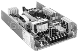
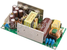
XP POWER JPS250PS15C 250/350W AC/DC U-Channel Power Supply
Part Number
JPS250PS15C
Price
Request Quote
Manufacturer
XP POWER
Lead Time
Request Quote
Category
Power Supply Board
Specifications
Current Share
Current share on single output models & V1 & V2 of multi-output models (4 supplies can be paralleled)
Earth Leakage Current
3.0 mA max 264 VAC/60 Hz
Fan Output
See mechanical notes for ordering information
Hold Up Time
20 ms min at low line & rated load
Initial Set Accuracy
At 60% rated load ±1% on V1 & V2,
Input Current
2.75 A/1.40 A max at 115 VAC/ 230 VAC (JPS250)4.5 A/2.2 A max at 115 VAC/230 VAC (JPS350)
Input Frequency
47-63 Hz
Input Voltage
85-264 VAC (170-370 VDC)
Inrush Current
30 A at 115 VAC, 60 A at 230 VAC
Line Regulation
±0.5% at rated load across input voltage range
Load Regulation
±1% for single output models & V1 & V2 of multi-output models, ±5% for V3 & V4
Minimum Load
Single output models: No minimum loadrequired. Multi-output models, see note 4
Output Voltage
See tables
Output Voltage Trim
±10% on output 1 only (VR1)
Overload Protection
110-130% of max rated load on all O/Ps,auto recovery
Overtemperature
Shuts down at +110 °C, auto recovery,Protection measured internally
Overvoltage Protection
115-140% on single outputs & V1 of quad output models, recycle input to reset
Power Factor
0.9 typical
Remote On/Off
On
Remote Sense
Compensates for up to 0.5 V drop
Ripple & Noise
±1% max pk-pk, 15 MHz bandwidth,see note 2 under model tables
Short Circuit Protection
Trip and restart (Hiccup mode), auto recovery
Start Up Delay
2 s typical
Start Up Rise Time
80 ms typical (JPS250)100 ms typical (JPS350)
Temp. Coefficient
±0.05%/°C
Transient Response
4% max deviation, recovery to within 1% in 500 µs for a 25% load change
Features
- 200 W / 300 W with Convection Cooling
- AC OK & DC OK Signals
- High Efficiency - up to 88%
- Meets 1U, Low Profile Requirements
- Remote On/Off & Remote Sense
- Zero Voltage Switching Technology
Datasheet

Extracted Text
250/350 Watts xppower.com JPS250/350 Series • 200 W / 300 W with Convection Cooling • High Efficiency - up to 88% • Meets 1U, Low Profile Requirements • AC OK & DC OK Signals • Zero Voltage Switching Technology • Remote On/Off & Remote Sense • 3 Year Warranty Specification Input General Input Voltage • 85-264 VAC (170-370 VDC) Efficiency • Up to 88% Input Frequency • 47-63 Hz Isolation • 3000 VAC Input to Output Input Current • 2.75 A/1.40 A max at 115 VAC/ 230 VAC (JPS250) 1500 VAC Input to Ground 4.5 A/2.2 A max at 115 VAC/230 VAC (JPS350) 500 VAC Output to Ground Inrush Current • 30 A at 115 VAC, 60 A at 230 VAC Switching Frequency • 120 kHz typical for PFC and PWM 3 Power Factor • 0.9 typical Power Density • 4.96 W/In Earth Leakage Current • 3.0 mA max 264 VAC/60 Hz Signals • AC OK, DC OK, Remote On/Off (see control and supervisory signals) Input Protection • Internal T5 A, 250 VAC fuse (JPS250) Internal T6.3 A, 250 VAC fuse (JPS350) MTBF • 125 kHrs to MIL-HDBK-217F at +50 °C, GB (JPS250) Output 146 kHrs to MIL-HDBK-217F at +50 °C, GB (JPS350) Output Voltage • See tables Output Voltage Trim • ±10% on output 1 only (VR1) Initial Set Accuracy • At 60% rated load ±1% on V1 & V2, Environmental ±5% on V3 & V4 Operating Temperature • 0 °C to +70 °C, (see derating curve) Minimum Load • Single output models: No minimum load Full power to +50 °C required. Multi-output models, see note 4 Cooling • 250 W with 18 CFM airflow (JPS250) Start Up Delay • 2 s typical 200 W convection cooling (JPS250) Start Up Rise Time • 80 ms typical (JPS250) 350 W with 18 CFM airflow (JPS350) 100 ms typical (JPS350) 300 W convection cooling (JPS350) Hold Up Time • 20 ms min at low line & rated load Operating Humidity • 5-95% RH, non-condensing Line Regulation • ±0.5% at rated load across input voltage range Storage Temperature • -20 °C to +85 °C Load Regulation • ±1% for single output models & V1 & V2 of Operating Altitude • 2000 m multi-output models, ±5% for V3 & V4 Vibration • 2 g, 10 Hz to 55 Hz, 30 mins each axis Transient Response • 4% max deviation, recovery to within 1% in 500 μs for a 25% load change EMC & Safety Ripple & Noise • ±1% max pk-pk, 15 MHz bandwidth, Emissions • EN55022, level B conducted see note 2 under model tables FCC 20780, level B conducted Overvoltage Protection • 115-140% on single outputs & V1 of quad Harmonic Currents • EN61000-3-2 output models, recycle input to reset ESD Immunity • EN61000-4-2, level 3 Perf Criteria A Overtemperature • Shuts down at +110 °C, auto recovery, Radiated Immunity • EN61000-4-3, 10 V/m Perf Criteria A Protection measured internally EFT/Burst • EN61000-4-4, level 3 Perf Criteria A Overload Protection • 110-130% of max rated load on all O/Ps, auto recovery Surge • EN61000-4-5, level 3 Perf Criteria A Short Circuit Protection • Trip and restart (Hiccup mode), auto recovery Dips and Interruptions • EN61000-4-11, 30% 10 ms, 60% 100 ms, 100% 5000 ms, Perf Criteria A, B, B Temp. Coefficient • ±0.05%/°C Safety Approvals • EN60950-1, UL60950-1, Remote Sense • Compensates for up to 0.5 V drop CSA C22.2 No. 60950-1, CE Mark LVD Remote On/Off • On = Logic Low or Open, Off = Logic High Current Share • Current share on single output models & V1 & V2 of multi-output models (4 supplies can be paralleled) Fan Output • See mechanical notes for ordering information AC-DC AC-DC JPS250 - Single Output Models and Ratings Output Current Output Output Ripple & Noise Model (1) (3) Power Voltage Pk-Pk Number Convection-cooled 18 CFM 225 W 5 V 36.0 A 45.0 A 50 mV JPS250PS05C†^ 12 V 17.0 A 21.0 A 120 mV JPS250PS12C†^ 15 V 13.5 A 17.0 A 120 mV JPS250PS15C†^ 250 W 24 V 8.5 A 10.4 A 200 mV JPS250PS24C†^ 48 V 4.3 A 5.2 A 200 mV JPS250PS48C†^ Notes 1. Maximum power with 18 CFM forced air is 250 W, or 200 W with convection cooling. 2. Ripple and noise measured over 15 MHz bandwidth with a 0.47 μF capacitor. 3. For non-current share version delete suffix ‘C’ from model number. † Available from Farnell. See pages 266-269. ^ Available from Newark. See pages 270-272. Mechanical Details All models (except JPS250PS05) 8.00 (203.2) PIN CONNECTIONS TB2 TB4 A B B A Pin VR1 JPS250PS05 All other models All models 10 L TB4 2 N Voltage Adj. 1 1 +5 V +V Signal 0 V + E TB3 - 2 +5 V +V DC OK TB1 1 3.75 4.20 3 0 V +V AC OK (95.3) (106.7) 4 0 V 0 V Remote On/Off TB2 TRANSFORMER 5 0 V 0 V +Sense 6 6 0 V 0 V -Sense A B B A (5) 7 +5 V Current Share 8 +5 V N/C 5.50 (139.0) 6.50 (165.1) 9 N/C 10 N/C 0.30 7.40 (188.0) (7.6) A A 1.51 Notes B (38.3) B 0.75 (19.1) 1. TB3 is for fan, with Molex 5045-02A or equivalent. 5 V model: 5 V at 390 mA, 24 V model: 24 V at 80 mA, 0.36 all other models: 12 V at 112 mA (9.1) 2. TB1 (AC input) and TB2 (DC output) are terminal blocks. 3. TB4 signal connector is Molex 70246-10 or equivalent. 4. Fan cover option available, order part number: † 5 V models: JPS250 F/CVR 5 ^ † 12, 15 & 48 V models: JPS250 F/CVR ^ † 24 V models: JPS250 F/CVR 24 ^ JPS250PS05 Or add suffix ‘-E’ to model number to receive unit with fan cover fitted. 4.2 x 8 x 2.48 (106.7 x 203.2 x 62.9). 5. For current share operation connect current share (pin 7) between 8.00 (203.2) units. For non ‘C’ models pin 7 (current share) is not used. 6. Input and output terminal screw tightening torque 9 lbs-in (1.0 Nm) VR1 2 10 A B maximum. TB4 L Voltage Adj. 1 N 1 E Fixing Holes: TB1 A = #6-32 screw mounting holes 3.75 4.20 (95.3) B = M3 x 0.5 screw mounting holes (106.7) TB2 Maximum mounting screw penetration is 0.16 (4.0) from chassis TRANSFORMER outer surface. + TB3 - 8 A A B B All dimensions are in inches (mm) Tolerance: ±0.03 (0.8) max 1.30 (32.1) 5.50 (139.0) 0.70 (19.1) 6.50 (165.1) Weight: 1.65 lbs (750 g) approx. JPS250 - Multi Output Models and Ratings Output 1 Output 2 Output 3 Output 4 Model Output Conv. Max Output Conv. Max Output Conv. Max Output Conv. Max (3) Number V1 Cooled 18 CFM V2 Cooled 18 CFM V3 Cooled 18 CFM V4 Cooled 18 CFM 3.3 V 16.0 A 20 A 5 V 12 A 20 A 12 V 5 A 6 A -12 V 1 A 2 A JPS250PQ46C 5.0 V 17.5 A 30 A 12 V 7 A 8 A -12 V 2 A 3 A -5 V 1 A 2 A JPS250PQ41C 5.0 V 20.0 A 25 A 12 V 4 A 6 A 24 V 2 A 3 A -12 V 1 A 2 A JPS250PQ47C 5.0 V 20.0 A 25 A 15 V 3 A 5 A 24 V 2 A 3 A -15 V 1 A 2 A JPS250PQ48C Notes 1. Maximum power with 18 CFM forced air is 250 W, or 200 W with convection cooling. 2. Ripple and noise measured over 15 MHz bandwidth with a 0.47 μF capacitor. 3. For non current share option delete suffix ‘C’ from model number. 4. All models require 2 A minimum load on V1. On V2, JPS250PQ46 requires 1 A and JPS250PQ41 requires 0.5 A. † Available from Farnell. See pages 266-269. ^ Available from Newark. See pages 270-272. Mechanical Details 8.00 (203.2) PIN CONNECTIONS - TB3 Pin PQ41 PQ46 PQ47 PQ48 1 L 1 +5 V +12 V +5 V +5 V N Voltage Adj. E 2 +5 V -12 V +5 V +5 V TB3 TRANSFORMER TB1 2 10 VR1 3 0 V +5 V 0 V 0 V 4.20 TB2 (106.7) VR2 1 8 4 0 V +5 V 0 V 0 V 5 0 V 0 V 0 V 0 V 6 -5 V 0 V -12 V -15 V Safety earth connection TB5 7 -12 V 0 V +24 V +24 V + - 8 +12 V 0 V +12 V +15 V 9 +3.3 V 10 +3.3 V 0.30 0.16 (4.0) 7.40 (187.9) (7.6) A A 1.30 1.50 B B (33.1) (38.1) 0.75 PIN CONNECTIONS - TB2 (19.1) Pin PQ41 PQ46 PQ47 PQ48 0.36 (9.1) 1 +5 V +S +3.3 V +S +5 V +S +5 V +S (5) (5) (5) 2 +5 V PS +5 V -S +5 V PS +5 V PS (5) 3 +12 V +S +3.3 V PS +12 V +S +15 V +S 8.00 (203.2) 4 DC OK DC OK DC OK DC OK 5 +12 V -S +5 V +S +12 V -S +15 V -S A B BA 6 +5 V -S +3.3 V -S +5 V -S +5 V -S (5) (5) (5) (5) 7 +12 V PS +5 V PS +12 V PS +15 V PS 8 Remote On/Off Remote On/Off Remote On/Off Remote On/Off 3.75 (95.3) 9 AC OK AC OK AC OK AC OK 10 0 V 0 V 0 V 0 V 1.30 (32.1) 0.70 (19.1) A B BA Notes 5.50 (139.0) 0.22 1. TB5 is for fan with Molex 5045-02A or equivalent. 12 V at 112 mA. (5.7) 6.50 (165.1) 2. TB1 (AC input) and TB3 (DC output) are terminal blocks. 3. TB2 signal connector is Molex 70246-10 or equivalent. 4. Fan cover option available, order part number: † † PQ41, PQ46 & PQ47: JPS250 F/CVR ^ PQ48: JPS250 F/CVR 24 ^ Fixing Holes: or add suffix ‘-E’ to model number to receive unit with fan cover fitted. A = #6-32 screw mounting holes 4.2 x 8 x 2.48 (106.7 x 203.2 x 62.9). B = M3 x 0.5 screw mounting holes 5. PS - Current share on ‘C’ models only. Maximum mounting screw penetration is 0.16 (4.0) from chassis outer surface. No connection on standard models. 6. VR2 is for production setting only. 7. Input terminal screw tightening torque 9 lbs-in (1.0 Nm) maximum. All dimensions are in inches (mm). 8. Output terminal screw tightening torque 4 lbs-in (0.45 Nm) maximum. Tolerance: ±0.03 (0.8) max. Weight: 1.65 lbs (750 g) approx. AC-DC AC-DC JPS350 - Single Output Models and Ratings Output Current Output Output Ripple & Noise Model (2) (1) Power Voltage Pk-Pk Number Convection-cooled 18 CFM 315 W 5 V 54.0 A 63.0 A 50 mV JPS350PS05C†^ 12 V 25.0 A 30.0 A 120 mV JPS350PS12C†^ 15 V 20.0 A 24.0 A 120 mV JPS350PS15C†^ 350 W 24 V 13.0 A 15.0 A 200 mV JPS350PS24C†^ 48 V 6.5 A 7.3 A 200 mV JPS350PS48C†^ Notes 1. For non-current share version delete suffix ‘C’ from model number. 2. Ripple and noise measured over 15 MHz bandwidth with a 47 μF electrolytic capacitor and 0.47 μF ceramic capacitor. † Available from Farnell. See pages 266-269. ^ Available from Newark. See pages 270-272. Mechanical Details All models (except JPS350PS05) PIN CONNECTIONS TB2 TB4 Pin 9.00 (228.6) JPS350PS05 All other models All models 1 +5 V +V N/C A B B A L 2 +5 V +V N/C N 1 3 0 V +V +Remote sense E TB1 4 0 V 0 V DC OK 4.50 5.00 5 0 V 0 V -Remote sense (114.3) (127.0) TRANSFORMER 6 6 0 V 0 V N/C TB2 (5) 2 10 7 +5 V Current Share + Voltage Adj. 1 8 +5 V Remote On/Off TB4 - TB3 A B B A 9 AC OK VR1 0.75 10 0 V 6.50 (164.4) 0.25 (19.1) (6.75) 7.50 (190.5) 0.50 8.00 (203.2) (12.7) Notes A A 1.60 B B (40.6) 0.87 1. TB3 is for fan, with Molex 5045-02A or equivalent. 12 V at 112 mA (22.0) (except JPS350PS05, 5 V at 390 mA). 0.47 2. TB1 (AC input) and TB2 (DC output) are terminal blocks. (12.0) 3. TB4 signal connector is Molex 70246-10 or equivalent. 4. Fan cover option available, order part number: † 5 V models: JPS350 F/CVR 5 ^ † All other models: JPS350 F/CVR ^ Alternatively, add suffix ‘-E’ to model number to receive fan cover fitted JPS350PS05 to the unit 4.95 x 8.92 x 2.48 (127.0 x 228.6 x 62.9). 5. For current share operation, connect current share (pin 7) between units. For non ‘C’ models pin 7 is not used. 9.00 (228.6) 6. Input and output terminal screw tightening torque 9 lbs-in (1.0 Nm) maximum. A A B B 1 2 Voltage Adj. L TB4 VR1 N 10 E Fixing Holes: 1 TB1 A = #6-32 screw mounting holes TRANSFORMER 4.50 5.00 B = M3 x 0.5 screw mounting holes (114.3) (127.0) Maximum mounting screw penetration is 0.16 (4.0) from chassis outer surface. 8 TB3 TB2 All dimensions are in inches (mm) A B B A + - Tolerance: ±0.03 (0.8) max. 0.75 Weight: 2.12 lbs (960 g) approx. 0.25 6.50 (164.4) (19.1) (6.75) 7.50 (190.5) JPS250/350 Control & Supervisory Signals AC OK Signal DC OK Signal +5 V +5 V 330 R 330 R DC OK (HIGH) AC OK (HIGH) DC OK AC OK GND GND DC NOT OK (LOW) AC NOT OK (LOW) AC OK is a TTL signal which goes LOW when input falls out of DC OK is a TTL signal which goes LOW when PSU is in an overcurrent specification. Source current is 1 mA, sink current is 6 mA. condition, overvoltage condition, disabled or when output falls out of regulation. Source current is 1 mA, sink current is 6 mA. Remote On/Off Control (Inhibit) Parallel Connection Utilizing Optional Current Share Output Supply 1 OUTPUTS OFF (5V) Remote On/Off Return Current Share V1 LOAD Ground Return OUTPUTS ON (0 V or open circuit) Output Supply 2 Return Current Share To turn off the output, apply 5 V to the remote On/Off. Remote Sense Connection + Output CD + Sense + Twisted Pair LOAD CL Supply - Sense - CD Output - Notes: 1. CD is 0.1 μF ceramic capacitor. 2. CL i s 47 μF electrolytic capacitor. AC-DC AC-DC 1.70 (43.2) JPS250/350 Control & Supervisory Signals Derating Curve 100 90 JPS250PS with 18 CFM Fan 80 L 70 JPS250PS Convection-cooled O 60 A D 50 40 %) 30 20 10 0 0 10 20 30 40 80 50 60 70 Ambient Temperature (˚C) JPS350 with 18 CFM Fan 100 90 80 JPS350 Convection-cooled L 70 O 60 A 50 D 40 (%) 30 20 10 0 0 10 20 30 40 50 60 70 80 Ambient Temperature (°C) Cover Option See mechanical details notes for ordering information. Typical internal clearance 0.15 (3.8) 4 x M3 x 6 C/S head fixing screws in existing countersunk holes 11-Apr-11 2.48 (62.9)
Frequently asked questions
How does Industrial Trading differ from its competitors?

Is there a warranty for the JPS250PS15C?
Which carrier will Industrial Trading use to ship my parts?
Can I buy parts from Industrial Trading if I am outside the USA?
Which payment methods does Industrial Trading accept?
Why buy from GID?

Quality
We are industry veterans who take pride in our work

Protection
Avoid the dangers of risky trading in the gray market

Access
Our network of suppliers is ready and at your disposal

Savings
Maintain legacy systems to prevent costly downtime

Speed
Time is of the essence, and we are respectful of yours
Related Products

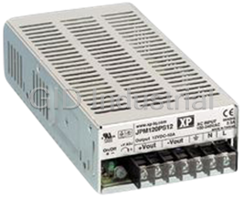
Xp Power JPM160PS13 power supply PSU, 160W, 13.5V, 11.8A industrial type
Request a Quote

The quote request has been received
Close

Facing challenges or have inquiries? Feel free to contact us!
Call Us +1-469-283-2440
What they say about us
FANTASTIC RESOURCE
One of our top priorities is maintaining our business with precision, and we are constantly looking for affiliates that can help us achieve our goal. With the aid of GID Industrial, our obsolete product management has never been more efficient. They have been a great resource to our company, and have quickly become a go-to supplier on our list!
Bucher Emhart Glass
EXCELLENT SERVICE
With our strict fundamentals and high expectations, we were surprised when we came across GID Industrial and their competitive pricing. When we approached them with our issue, they were incredibly confident in being able to provide us with a seamless solution at the best price for us. GID Industrial quickly understood our needs and provided us with excellent service, as well as fully tested product to ensure what we received would be the right fit for our company.
Fuji
HARD TO FIND A BETTER PROVIDER
Our company provides services to aid in the manufacture of technological products, such as semiconductors and flat panel displays, and often searching for distributors of obsolete product we require can waste time and money. Finding GID Industrial proved to be a great asset to our company, with cost effective solutions and superior knowledge on all of their materials, it’d be hard to find a better provider of obsolete or hard to find products.
Applied Materials
CONSISTENTLY DELIVERS QUALITY SOLUTIONS
Over the years, the equipment used in our company becomes discontinued, but they’re still of great use to us and our customers. Once these products are no longer available through the manufacturer, finding a reliable, quick supplier is a necessity, and luckily for us, GID Industrial has provided the most trustworthy, quality solutions to our obsolete component needs.
Nidec Vamco
TERRIFIC RESOURCE
This company has been a terrific help to us (I work for Trican Well Service) in sourcing the Micron Ram Memory we needed for our Siemens computers. Great service! And great pricing! I know when the product is shipping and when it will arrive, all the way through the ordering process.
Trican Well Service
GO TO SOURCE
When I can't find an obsolete part, I first call GID and they'll come up with my parts every time. Great customer service and follow up as well. Scott emails me from time to time to touch base and see if we're having trouble finding something.....which is often with our 25 yr old equipment.
ConAgra Foods