

 Manufacturers
RADISYS CE370A-0

Description
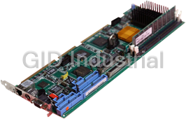
RadiSys CE370A-0 CPU Boards-Intel 1.0GHz ULV Celeron M 373 BGA processor, no memory module, RoHS
Part Number
CE370A-0
Price
Request Quote
Manufacturer
RADISYS
Lead Time
Request Quote
Category
Single Board Computers
Specifications
Form Factor
COM Express
System Chipset
Intel ICH
Audio
Intel High Definition Audio (HDA) or AC'97 2.3 CODEC
BGA options
1.5GHz Celeron M 370, 1.0GHz ULV Celeron M 373, 1.4GHz LV Pentium M 738, 2.0GHz Pentium M 760
BIOS
Phoenix FirstBIOS Notebook Pro BIOS in 1MB Firmware Hub (FWH)
Chipset
Mobile Intel 915GM Express chipset with ICH6-M I/O Hub chipset
Compliance
PICMG COM Express R1.0 basic form factor, type 2
Connectors
COM Express 440pin (two 220-pin, 0.5mm pitch receptacle)
Dimensions
95mm x 125mm - COM Express basic form factor
Front Side Bus (FSB)
400/533 MHz
IDE
One Ultra ATA100/66/33 port
L2 Cache
2MB Pentium M 1MB Celeron M, 512MB ULV Celeron M
Memory Capacity Maximum
1G (Gbit technology), minimum 128MB
Memory Type
200-pin SO-DIMM socket for up to 1G DDR2-400/533MHz memory (PC2-3200/43002) Non-ECC
Network
IEEE 802.3 10/100/1000Base-T compliant physical layer interface
OS Support
Windows XP, Windows XP Embedded, Red-Hat Desktop Linux, Windows 2000, MontaVista Linux Professional Edition, VxWorks 5.5, OS/9, QNX Neutrino
PCI
PCI 2.3 32-bit 33MHz, six logical devices
PCI Express
Three x1 interfaces
Power Management
S0, S3, S4 and S5
Power Requirement
+12V input from carrier board, + 5V standby
Processor
Intel Celeron M
SATA
Two SATA 150 ports
USB
Eight USB 2.0 ports
Video
Intel Integrated chipset graphics supporting dual independent displays; Dual SDVO; LVDS 18-bit dual channel; Analog VGA; TV-Out PCI Express x16 external graphics port (multiplexed on DVI interface pins)
Datasheet

Extracted Text
PROCELERANT™ CE915GM COM EXPRESS MODULE PRODUCT NOTES CE760A-0, CE738A-0, CE373A-0, CE370A-0, CE738A-E-512 What’s new in the product family New COM Express modules This release introduces four new Procelerant™ CE915GM COM Express™ embedded computing modules with simplified BIOS maintenance, improved thermal performance, and improved compatibility with ATX power supplies. All modules are RoHS compliant. New Model Previous Model Description CE760A-0 CE760 CE915GM with Intel 2GHz Pentium M 760 BGA processor, memory module not included CE738A-0 CE738 CE915GM with Intel 1.4GHz LV Pentium M 738 BGA processor, memory module not included CE373A-0 CE373 CE915GM with Intel 1.0GHz ULV Celeron M 373 BGA processor, memory module not included CE370A-0 CE370 CE915GM with Intel 1.5GHz Celeron M 370 BGA processor, memory module not included CE738A-E-512 CE738 CE915GM with Intel 1.4GHz LV Pentium M 738 BGA processor, extended temperature range (-25ºC to 70ºC), and 512MB memory module Enhancements Simplified BIOS maintenance A new BIOS operation mode header on the COM Express modules enables two maintenance tasks that previously required more complicated steps involving the CR100 carrier board. The CMOS RAM can be cleared by inserting a jumper on pins 3 and 4 of the new header. BIOS recovery can be initiated by inserting a jumper on pins 2 and 3 of the new header. Copyright © 2007 by RadiSys Technology (Ireland) Ltd. All rights reserved. RadiSys is a registered trademark and Procelerant is a trademark of RadiSys Corporation. All other trademarks, registered trademarks, service marks, and trade names are the property of www.radisys.com their respective owners. 007-02536-0000 • April 2007 What’s new in the product family New reset and POST LEDs New LEDs, reset and POST, provide visual indications of the system status when the module has not yet been installed in a chassis. The LEDs are on the lower edge of the modules to the right of the BIOS ROM chip. The reset LED illuminates while the system resets. The POST LED turns on and off four times during boot up to identify eight different stages of the power on self tests. This information is helpful If the CE915GM module is installed on a carrier board that does not have PCI or LPC interfaces to accommodate a POST80 diagnostic card. Technical publications changes A stand-alone reference manual for the CR100 carrier board was developed for a previous release, and is available for download from the RadiSys Web site. Redundant information has been pulled out of the CE915GM Product Manual and COM Express Carrier Board Design Guidelines to simplify these manuals and avoid confusion. The online help in the BIOS setup utility, available when pressing F2 during boot up, has been updated and provides information about available options in the BIOS setup. As a result, the lengthy BIOS configuration screens have been removed from the CE915GM Product Manual to simplify the manual. Resolved limitations over earlier CE915GM models The following issues that were identified on the previous CE915GM models have been resolved in the new models. Incompatability with some ATX-compliant power supplies The CE915GM models were incompatible with some ATX-compliant power supplies, such as ® the Sparkle FSP350-601U. ® Resolution: The new CE915GM models fully comply with the Intel ATX12V Power Supply Design Guidelines. Issue No: RSYS00008589 Thermal performance issues at maximum temperature When operating the CE760 and CE373 modules at the maximum-rated ambient temperature of 60° C, processor-intensive applications caused the core frequency to be reduced temporarily to avoid overheating. A reduction in the core frequency results in slower processor performance. Resolution: A new backer plate is supplied with CE-AHSA, CE-PHSA and CE-PHS17A thermal solutions for all of the new CE915GM models. The backer plate substantially improves thermal performance, and has resolved this issue. Issue No: RSYS00010289 2 Application notes Application notes Using a USB optical disk drive to install the operating system Follow the steps below if you are using a USB optical disk drive (CD-ROM or DVD) as a bootable drive to install the operating system. 1. With the USB drive disconnected, power on the system. 2. Press F2 to enter the BIOS setup utility. On the Boot > Boot Order menu, set the B oot Priority Order to [USB CD-ROM] first. Optional step: on the Configuration > USB Configuration menu, set HDD Boot Translation to [Force63]. This allows the system to detect the USB drive faster. Change this setting back to [Auto] when ready to boot from the hard disk. 3. Power on the USB drive and insert the CD-ROM/DVD. Make sure the drive detects the presence of the disk. 4. Connect the USB drive’s cable to the USB port on the carrier board’s rear I/O panel. 5. With the USB drive still running, reset the system. 3
Frequently asked questions
How does Industrial Trading differ from its competitors?

Is there a warranty for the CE370A-0?
Which carrier will Industrial Trading use to ship my parts?
Can I buy parts from Industrial Trading if I am outside the USA?
Which payment methods does Industrial Trading accept?
Why buy from GID?

Quality
We are industry veterans who take pride in our work

Protection
Avoid the dangers of risky trading in the gray market

Access
Our network of suppliers is ready and at your disposal

Savings
Maintain legacy systems to prevent costly downtime

Speed
Time is of the essence, and we are respectful of yours
Related Products
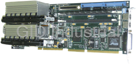
Radisys 97-9025-02 CPU Board with Socket 370 and 2 memory slots
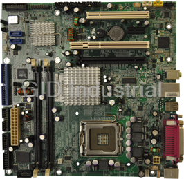
RadiSys Endura BG845G Motherboard, Intel Pentium 4 Processor, and Intel 845GV + ICH4 Chipset
Request a Quote

The quote request has been received
Close

Facing challenges or have inquiries? Feel free to contact us!
Call Us +1-469-283-2440
What they say about us
FANTASTIC RESOURCE
One of our top priorities is maintaining our business with precision, and we are constantly looking for affiliates that can help us achieve our goal. With the aid of GID Industrial, our obsolete product management has never been more efficient. They have been a great resource to our company, and have quickly become a go-to supplier on our list!
Bucher Emhart Glass
EXCELLENT SERVICE
With our strict fundamentals and high expectations, we were surprised when we came across GID Industrial and their competitive pricing. When we approached them with our issue, they were incredibly confident in being able to provide us with a seamless solution at the best price for us. GID Industrial quickly understood our needs and provided us with excellent service, as well as fully tested product to ensure what we received would be the right fit for our company.
Fuji
HARD TO FIND A BETTER PROVIDER
Our company provides services to aid in the manufacture of technological products, such as semiconductors and flat panel displays, and often searching for distributors of obsolete product we require can waste time and money. Finding GID Industrial proved to be a great asset to our company, with cost effective solutions and superior knowledge on all of their materials, it’d be hard to find a better provider of obsolete or hard to find products.
Applied Materials
CONSISTENTLY DELIVERS QUALITY SOLUTIONS
Over the years, the equipment used in our company becomes discontinued, but they’re still of great use to us and our customers. Once these products are no longer available through the manufacturer, finding a reliable, quick supplier is a necessity, and luckily for us, GID Industrial has provided the most trustworthy, quality solutions to our obsolete component needs.
Nidec Vamco
TERRIFIC RESOURCE
This company has been a terrific help to us (I work for Trican Well Service) in sourcing the Micron Ram Memory we needed for our Siemens computers. Great service! And great pricing! I know when the product is shipping and when it will arrive, all the way through the ordering process.
Trican Well Service
GO TO SOURCE
When I can't find an obsolete part, I first call GID and they'll come up with my parts every time. Great customer service and follow up as well. Scott emails me from time to time to touch base and see if we're having trouble finding something.....which is often with our 25 yr old equipment.
ConAgra Foods