

 Manufacturers
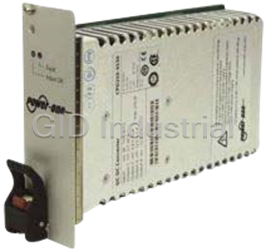
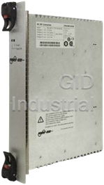
POWER-ONE HPF5
Description
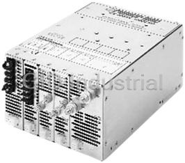
Power-One HPF5 Series 2000W Active PFC, EN61000-3-2 Compliant High Power Modular Power Supply.
Part Number
HPF5
Price
Request Quote
Manufacturer
POWER-ONE
Lead Time
Request Quote
Category
Power Supply
Datasheet

Extracted Text
MODULAR HIGH POWER SERIES FROM 500 TO 4000 WATTS RELIABILITY FLEXIBILITY PERFORMANCE • Demonstrated DC output module MTBF • Modular construction; over 10 million • Single outputs fully regulated and isolated. of greater than 5 million hours. configurations available. • PFC models meet EN61000-3-2 and • Ruggedized AC input sections incorporate • Up to 21 outputs per power supply from EN60555-2. extensive transient protection. 1.0 to 48VDC. • EN60950/UL1950 approved. CE Marked • Vibration tested at 6 GRMS, 3 axis, • Parallelable outputs with current sharing. to the Low Voltage Directive. 10Hz to 2000Hz. • System inhibit and individual module • No minimum loads required on most • Two year warranty. output inhibit capability. outputs. • Metric mounting available on selected models. MODULAR HIGH POWER SERIES PRODUCT OVERVIEW METRIC MOUNTING SMF3 HMF3 HMF5 SMM2 SMM3 SMM5 HMM5 HMM7 RMM5 CHASSIS STANDARD SPF3 HPF3 HPF5 SPM2 SPM3 SPM5 HPM5 HPM7 RPM5 OUTPUT POWER AND POWER FACTOR .99 PFC to meet EN60555 YES YES YES N/A N/A N/A N/A N/A N/A Max output wattage at high range line input 1350 2000 2000 500 1000 1500 2000 2500 4000 Max output wattage at low range line input* 1000 1500 1500 500 1000 1500 N/A N/A N/A INPUT VOLTAGE SPECIFICATIONS** High range VAC input 160-264 160-264 160-264 175-264 175-264 175-264 180-264 180-264 180-264 Low range VAC input 85-159 85-159 85-159 90-132 90-132 90-132 N/A N/A N/A VAC input selection Wide Range Wide Range Wide Range Manual Manual Manual N/A N/A N/A VAC input phases single single single single single single single single three OUTPUT MODULE SPECIFICATIONS Max # of outputs 9 9 15 6 9 15 15 21 15 # of module slots 335235575 MECHANICAL SPECIFICATIONS Chassis size H x W x L, inches 5 x 5.5 x 12.5 5 x 5.5 x12.5 5 x 8 x 11 5 x 3 x 11 5 x 5.5 x 11 5 x 8 x 11 5 x 8 x 11 5 x 11 x 13 5 x 8 x 15 Chassis size H x W 127 x 140 127 x 140 127 x 203 127 x 76 127 x 140 127 x 203 127 x 203 127 x 280 127 x 203 x L, millimeters x 318 x 318 x 280 x 280 x 280 x 280 x 280 x 330 x 381 INPUT TRANSIENT PROTECTION SPECIFICATIONS ESD Immunity Level 4 Level 4 Level 4 Consult Level 4 Level 4 Level 4 Level 4 Level 4 EN61000-4-2, 15kV/8kV15kV/8kV15kV/8kVFactory15kV/8kV15kV/8kV15kV/8kV15kV/8kV15kV/8kV RF Susceptibility Level 3 Level 3 Level 3 Consult Level 3 Level 3 Level 3 Level 3 Level 3 EN61000-4-3 10V/m 10V/m 10V/m Factory 10V/m 10V/m 10V/m 10V/m 10V/m Fast Transient/Burst Level 3 Level 3 Level 3 Consult Level 3 Level 3 Level 3 Level 3 Level 3 EN61000-4-4 +2kV +2kV +2kV Factory +2kV +2kV +2kV +2kV +2kV Surge Immunity Class 4 Class 4 Class 4 Consult Class 4 Class 4 Class 4 Class 4 Class 4 EN61000-4-5 (Line-Line) 2kV 2kV 2kV Factory 2kV 2kV 2kV 2kV 2kV Surge Immunity Class 4 Class 4 Class 4 Consult Class 4 Class 4 Class 4 Class 4 Class 4 EN61000-4-5 (line-Gnd) 4kV 4kV 4kV Factory 4kV 4kV 4kV 4kV 4kV *Maximum wattage above 100VAC input for SPF/HPF **Autorange input denotes continuous operation from 85 to 264 VAC NUCLEAR AND MEDICAL APPLICATIONS Power-One products are not authorized for use as critical components in life support systems, equipment used in hazardous environments, or nuclear control systems without the express written consent of the President of Power-One, Inc. TECHNICAL REVISIONS The appearance of products, including safety agency certifications pictured on labels, may change depending on the date manufactured. Specifications are subject to change without notice. Rev. 04/2000 1 MODULAR HIGH POWER SERIES FROM 500 TO 4000 WATTS SPF3/SMF3* SPM2/SMM2* HPM5/HMM5* 1350 WATTS 500 WATTS 2000 WATTS .99 PFC HPF3/HMF3* SPM3/SMM3* HPM7/HMM7* 2000 WATTS 1000 WATTS 2500 WATTS .99 PFC HPF5/HMF5* SPM5/SMM5* RPM5/RMM5* 2000 WATTS 1500 WATTS 4000 WATTS .99 PFC 3 PHASE INPUT *Metric mounting models meet all performance specifications of models with SAE mounting inserts. 2 MODULAR HIGH POWER SERIES FROM 500 TO 4000 WATTS SYSTEM BLOCK DIAGRAM SELECTION AND CONFIGURATION The Modular High Power Series products are modular power The modularity of the International Series High Power systems using separate switch-mode DC Output Modules to products allows the user to specify a power system configured provide the voltage and current ratings required by each from a wide selection of standard off-the-shelf plug in specific application. modules. The power system is delivered completely assembled, burned in, and tested. A part number comprised of a series The system is based on a 300 VDC System Power Bus derived designation, module listing, and options can be configured as from either the AC utility line, or a user supplied 300 VDC follows: source. This 300 VDC bus provides the bulk DC required by each output module for conversion to its specified output 1. Choose a chassis based on required wattage, number of voltage and current ratings. outputs, and power factor. 2. Select modules following the guidelines in the As shown in the block diagram, this independent modular configuration section. approach provides complete isolation between the outputs, as well as all other system elements. Also, the switching circuitry 3. Decide on the options. Standard options are listed in the of each output module is clocked and synchronized by the configuration section. Please call the factory for special Sync & Bias Supply section to reduce electrical interference requirements, such as logic option cards. between the outputs. ACTIVE RECTIFIER EMI AC INPUT SOFT & FILTER START FILTER 3 0 115/230 VAC SELECT 0 INRUSH LIMIT 300VDC DC OUTPUT MODULE #1 & INPUT V (OPTIONAL) POLARIZATION MOSFET RECTIFIER D DC OUTPUT #1 POWER & C SWITCH FILTER S Y MODULE CONTROL CONTROL S SIGNALS T SYNC & BIAS SUPPLY E DC OUTPUT MODULES #2, #3, #4 M OMITTED FOR CLARITY #1 RECTIFIER/FILTER & P DC OUTPUT MODULE #5 SYNC O MOSFET RECTIFIER W DC OUTPUT #5 BIAS SUPPLY POWER & RECTIFIER/FILTER & SYNC E INVERTER SWITCH FILTER CIRCUITS #2, #3, #4 R OMITTED FOR CLARITY B MODULE CONTROL U CONTROL RECTIFIER/FILTER SIGNALS S DC FAN #5 RECTIFIER/FILTER & SYNC SYSTEM SYSTEM CONTROL CONTROL SIGNALS 3 MODULAR HIGH POWER SERIES SELECTION AND CONFIGURATION CONFIGURATION NOTES • Not all modules can be used in all slots. Refer to the • Modules are designated in left to right in the part number but are installed right to left in the chassis. compatibility table below. • Fill blank slots with K or L option. • Single and double wide modules occupy one and two chassis slots respectively. Confirm that the total number of SLOT #5 #4 #3 #2 & #1 slots required does not exceed the chassis slot capacity. 1 + + 1 1 EXAMPLE: OUTPUTS SELECTED 5V @ 150A 2 - - 2 2 12V @ 20A + + 3 3 3 VOLT - - 4 4 4 ADJ. –12V @ 20A 5 VOLT VOLT ADJ. ADJ. 3 12 3 6 3 6 3 6 2 11 2 5 2 5 2 5 1 10 1 4 1 4 1 4 INPUT K B1 B1 A2 All chassis slots are numbered in right to left sequence STANDARD OPTIONS SYSTEM INHIBIT INPUT POWER FAIL WARNING (OPT A, B & C) OTHER OPTIONS (OPT M, N & P) POWER OUTPUT OPTION SIGNAL OUTPUT DESCRIPTION OPTION SIGNAL OUTPUT OPTION INHIBIT ENABLE K – Single Width Slot Blank Std Logic Low Open Ckt. or L – Double Width Slot Blank Open Collector Hi To Lo Logic High Std N Conducts See Paralleled Module Configurations Transition To Give Signal For Additional Options A Logic High Open Ckt. or Logic Low B Open Ckt. Logic Low or Logic High Open Collector Lo To Hi C Open Ckt. M P Opens To Logic High Transition or Logic Low Give Signal MODULE AND CHASSIS COMPATIBILITY Confirm that the number listed in the compatibility column of the slot closest to the input section but can use any module with a compatibility number of four or less in the two other slots. Bold the module selector guide is equal to or less than the lowest number specified for the module slots pictured below. Example: lines designate adjoining slots that can be used for double wide modules. The SPF3 can only use modules with a slot compatibility of 1 in SPF3/SMF3/HPF3/HMF3 HPF5/HMF5 RPM5 I I I N N N P P P U U U T T T SPM2 SPM3 SPM5/HPM5 HPM7 I I I I N N N N P P P P U U U U T T T T 4 MODULAR HIGH POWER SERIES MODULE SELECTOR GUIDE SINGLE VOLTAGE OUTPUT MODULES – SEE MECHANICAL DRAWINGS FOR OUTPUT CONNECTION DETAILS, STARTING ON PAGE A69 NOMINAL CURRENT (AMPS) SLOTS SLOT NOISE & RIPPLE (mV PK-PK) NOISE & RIPPLE (mV PK-PK) OUTPUT MODULE VOLTAGE @ 50°C (NOTE G) USED COMPATIBILITY TYPICAL (NOTE A) MAXIMUM (NOTE A) CONNECTION 1.0V 320 ER 2 5 30 100 Type III 1.5V/1.8V 35 T1 (Note K) 1 1 30 50 Type II 1.5V/1.8V 60 T6 (Note K) 1 1 30 50 Type I 1.5V/1.8V 250 T4 (Note K) 2 2 30 50 Type III 2.0V 80 F8 1 3 25 40 Type I 2V/2.2V 35 F1 (Note J) 1 1 20 50 Type II 2V/2.2V 60 AG (Note B, J) 1 1 30 50 Type I 2V/2.2V 60 F6 (Note J) 1 1 30 50 Type I 2V/2.2V 150 F2 (Note J) 2 2 30 50 Type III 2V/2.2V 180 CS (Note J) 2 5 30 50 Type III 2V/2.2V 250 F4 (Note J) 2 2 30 50 Type III 2V/2.2V 320 F7 (Note J) 2 5 30 100 Type III 2V/2.2V 375 QF (Note B, I) 2 5 30 50 Type III 2.3V 35 BJ 1 1 30 50 Type II 3.3V 35 H1 1 1 30 50 Type II 3.3V 60 H6 1 1 30 50 Type I 3.3V 80 H8 1 3 40 50 Type I 3.3V 90 DA 1 5 30 50 Type I 3.3V 150 H2 2 2 30 40 Type III 3.3V 250 H4 2 2 30 50 Type III 3.3V 320 H7 2 5 50 100 Type III 5V 35 A1 1 1 35 50 Type II 5V 60 A6 1 1 15 50 Type I 5V 80 A8 1 3 15 50 Type I 5V 90 DT 1 5 15 50 Type I 5V 150 A2 2 2 30 50 Type III 5V 220/250 A4 (Note H) 2 3/4 30 50 Type III 5V 320 A7 2 5 30 100 Type III 5V 375 QA 2 5 30 50 Type III 6V 35 AU 1 1 65 90 Type II 6V 100 CT 1 5 40 60 Type I 6V 120 BY 2 2 40 60 Type III 6V 250 CU 2 5 40 100 Type III 8V 65 AJ 2 2 53 80 Type III 10V 20 AW 1 1 66 100 Type II 10V 40 BE 1 3 40 60 Type I 10V 50 CV 1 5 66 100 Type I 10V 65 AQ 2 2 66 100 Type III 10V 160 CW 2 5 100 200 Type III 12V 20 B1 1 1 80 120 Type II 12V 40 B6 1 3 40 60 Type I 12V 65 B2 2 2 80 120 Type III 12V 80 BC 2 3 80 120 Type III 12V 135 DE 2 5 120 240 Type III 15V 16 AF (Note C) 1 1 15 35 Type II 15V 16 C1 1 1 100 150 Type II 15V 33 C6 1 3 30 60 Type I 15V 50 C5 1 5 100 150 Type I 15V 52 C2 2 2 100 150 Type III 24V 10 D1 1 1 160 240 Type II 24V 15 D6 1 2 80 120 Type II 24V 29 D8 1 4 60 100 Type I 24V 32 D2 2 2 160 240 Type III 24V 33 D5 1 5 60 100 Type I 28V 8.6 E1 1 1 200 280 Type II 28V 26 E8 1 4 70 100 Type I 28V 27 E2 2 2 150 280 Type III 28V 29 E5 1 5 70 100 Type I 36V 20 J8 1 4 100 200 Type I 36V 21 J2 2 2 100 200 Type III 36V 23 J5 1 5 100 200 Type I 48V 5 G1 1 1 400 480 Type II 48V 12.5 G4 (Note C) 1 3 40 60 Type I 48V 16 G2 2 2 135 200 Type III 48V 16 G8 1 4 60 100 Type I 48V 19 G6 1 5 60 100 Type I 5 MODULAR HIGH POWER SERIES MODULE SELECTOR GUIDE SINGLE OUTPUT, VARIABLE VOLTAGE MODULES NOMINAL CURRENT (AMPS) SLOTS SLOT NOISE & RIPPLE (mV PK-PK) NOISE & RIPPLE (mV PK-PK) OUTPUT MODULE VOLTAGE @ 50°C (NOTE G) USED COMPATIBILITY TYPICAL (NOTE A) MAXIMUM (NOTE A) CONNECTION 1.0V to 1.8V 320 ER 2 5 30 100 Type III 1.5V to 2.8V 375 QF (Note B) 2 5 50 50 Type III 1.9V to 3V 150 AB 2 2 50 50 Type III 14V to 24V 10 W1 1 1 80 120 Type II 14v to 24V 32 BS 2 2 135 200 Type III DUAL VOLTAGE OUTPUT MODULES NOMINAL CURRENT (AMPS) SLOTS SLOT NOISE & RIPPLE (mV PK-PK) NOISE & RIPPLE (mV PK-PK) OUTPUT MODULE VOLTAGE @ 50°C (NOTE G) USED COMPATIBILITY TYPICAL (NOTE A) MAXIMUM (NOTE A) CONNECTION 12/12 10/4 M4 Note D) 1 1 120 240 Type II ±12 10/10 B4 (Note E) 1 1 120 240 Type II ±15 8/8 C4 (Note E) 1 1 150 300 Type II ±20 5/5 BQ (Note E) 1 1 80 100 Type II ±24 5/5 D4 (Note E) 1 1 80 120 Type II TRIPLE OUTPUT VOLTAGE MODULES (Note D) NOMINAL CURRENT (AMPS) SLOTS SLOT NOISE & RIPPLE (mV PK-PK) NOISE & RIPPLE (mV PK-PK) OUTPUT MODULE VOLTAGE @ 50°C (NOTE G) USED COMPATIBILITY TYPICAL (NOTE A) MAXIMUM (NOTE A) CONNECTION 5/1.5/12 10/10/10 CA 1 1 N/A 100/100/120 Type II 5/2.2/12 10/10/10 W6 1 1 N/A 100/100/120 Type II 5/12/12 10/10/10 M6 1 1 N/A 50/120/120 Type II 5.2/12/12 15/8/8 BA 1 1 N/A 100/180/180 Type II 5.2/12/12 5/16/7 AE 1 1 N/A 60/160/120 Type II 5/12/24 10/10/5 U6 1 1 N/A 50/120/240 Type II 5/15/15 10/8/8 V6 1 1 N/A 50/150/150 Type II 5/24/24 10/5/5 R6 1 1 N/A 50/240/240 Type II 12/12/12 10/10/10 N6 1 1 N/A 120/120/120 Type II 5/15/12 10/8/10 EC 1 1 N/A 50/150/120 Type II 24/12/12 5/10/10 P6 1 1 N/A 240/120/120 Type II NOTES: A) The output noise and ripple measurement is bandwidth limited to 20MHz. B) Module is designed to accommodate output cable losses of up to one volt. C) Module is designed for use in applications demanding low noise and ripple. Consult factory for further specifications. D) All triple output modules, as well as the M4 dual output module, have floating outputs. Like voltages may be shared within the same module. All triple output adjustments and interface signals are for output #1. Consult factory for more information. E) The dedicated negative (-) output is quasiregulated. Both outputs require a small minimum load to perform to specification. Consult factory for more information. G) For ambient temperatures above 50°C, output current must be linearly derated to 50% at the maximum operational ambient temperature, 70°C. H) A4 module provides 220A in chassis with slot compatibility rating of 3, and 250A in chassis with slot compatibility rating of 4. I) Module output is wide range adjustable from 1.5 to 2.8 volts, factory preset to 2.0 volts. J) Module output is factory set to 2.0 volts. Output voltage will adjust +10% to 2.2 volts. K) Modules do not adjust -10% below 1.5V or +10% above 1.8V. Consult factory. 6 MODULAR HIGH POWER SERIES PARALLELED MODULE CONFIGURATIONS For applications that require an output current greater than listed in the Module Selector Guide, it is possible to achieve greater output through the paralleling of multiple single output modules. A performance aspect of the high power modular construction allows for paralleling of common voltage modules of the same or different current ratings for increased output capability. By connecting additional modules in parallel, it is possible to attain output currents up to 730A. All paralleling designations include factory-installed bus bars, as well as internally connected current sharing. Please consult factory for paralleling configurarions not shown. • Choose appropriate chassis and modules as shown in Selection and Configuration. • Note the output connection type as shown in the Module Selector Guide. • Select the paralleling suffix that corresponds to the selected output modules. • NOTE: Paralleling suffix follows after all other option codes. CHASSIS CHASSIS SLOT PARALLELING 7 6 5 4 3 2 1 SUFFIX EXAMPLE: REQUIREMENT: 5V @ 300A 3 SLOT CHASSIS: SPM3, SPF3, SMF3, HPF3, HMF3 II YA • Select Chassis: HPF3 III YB • Select Modules: A4 (5V @ 250A), A6 (5V @ 60A) II I I YC • Choose Corresponding Paralleling Suffix: YD • Final Part Number: HPF3A4A6YD I III YD II III YE 5 SLOT CHASSIS: LIMITATIONS FOR STANDARD SPM5, HPM5, HPF5, HMF5, RPM5 II YF PARALLELING SYSTEM III YG • Single output modules only N/U I II YJ • Ripple and Noise limit will be 20% II I I YJ over the largest value paralleled II I I I I YM II I I I YN LEGEND I III YP III III YH Type I = #10-32 studs Type II = Barrier Block II III III YR Type III = 5/16"-18 studs I III III YS 7 SLOT CHASSIS: HPM7 II YF III YG N/U I II YJ II I I YJ II I I I YN I III YP III III YH I III III YS III III III YT 7 MODULAR HIGH POWER SERIES DC OUTPUT MODULE SPECIFICATIONS SINGLE AND DUAL OUTPUT MODULES PARAMETER CONDITIONS/DESCRIPTION MIN NOM MAX UNITS Output Voltage Adjustment Range -10 +10 % Output Current At 0°C to 50°C ambient. See Module Selector Guide. Ambient Temperature Range 100% rated load. 0 50 °C Derated linearly to 50% load. 0 70 Initial Voltage Setting Factory set. -1 +1 % Output Voltage Adjustment -10 +10 % Margining/Remote Range. -10 +10 % Voltage Adjustment Programming sensitivity from 2.0V. -4 -5 -6 %/V Remote Voltage Sense Total cable drop. 0.5 V Temperature Coefficient 0 to 50 °C after initial 1 hour warmup. 0.01 0.02 %/°C Long Term Voltage Drift 1000 hours. 0.1% Line Regulation Over input operating range. 0.05 0.1 % ≤ 5 Volt Modules Load Regulation 0% to 100% load with remote sense. < 10 mV Single Output Modules 0% to 100% load without remote sense. < 60 mV Consult Factory For > 5 Volt Modules Specific Ratings 0% to 100% load with remote sense. < 30 mV 0% to 100% load without remote sense. < 75 mV Cross Regulation Between Single 0% to 100% load change. 0 % Output Modules in One Chassis Load Regulation, Dual Output Modules Positive Output 0% to 100% load with remote sense. < 30 mV 0% to 100% load without remote sense. < 75 mV Load Regulation, Dual Output Modules Negative Output 0% to 100% load. 5 % Cross Regulation, Dual Output Modules Positive Output 0% to 100% load change. 0.1 mV Cross Regulation, Dual Output Modules Negative Output 10% to 100% load change. 5 % Minimum Load Current Dual output modules only. See factory data sheets. 1 Amp Current Limit Factory set. As a % of full rated Io. Dual output modules use 110% 115% 120% Amp primary power limiting. See module ratings. Short Circuit Current As a % of full rated I0. 100% Amp Current Sharing Current sharing accuracy as a % of full rated I0.1% Overvoltage Protection Trip point as a % of V0 ≥ 5V. Resettable by recycling input. 115% 120% 125% V Reverse Polarity Protection Reverse current as a % of full rated Io. Reverse voltage externally applied. 100% Amp Logic LO = off 0.9 V Inhibit Sink current. 0.4 mA Logic HI = on 2 V Source current. 20 µA Logic LO (when V0 deviates ±3% to ±5% from adjusted set point). 0.9 V Output Good Signal Sink current. 40 mA Logic HI (with internal pull-up to 5V). 1.5 kΩ Noise and Ripple 20MHz bandwith. See module ratings. mVPP Transient Response 75% to 100% load step. 2% mVPK 50% to 100% load step. 4% Recovering to 1% within 400 µSec, Slew rate = 1A/µSec. Turn-On Delay After input applied. 1 Sec After inhibit released. 50 mS Rise Time 5% to 95% of V0. 50 mS Overshoot Overshoot as a % of V0 at turn on. 0% V Turn-Off Delay After inhibit or OVP trip. 500 µS Specifications in this section are general and may vary according to specific modules. 8 MODULAR HIGH POWER SERIES DC OUTPUT MODULE SPECIFICATIONS TRIPLE OUTPUT MODULES PARAMETER CONDITIONS/DESCRIPTION OUTPUT #1 OUTPUT #2 OUTPUT #3 MIN. NOM. MAX MIN. NOM. MAX MIN. NOM. MAX UNITS Output Current At 0°C to 50°C ambient. See module ratings. Ambient Temperature Range 100% rated load. 0 50 0 50 0 50 °C Derated linearly to 50% load. 70 70 70 Initial Voltage Setting Initial voltage set point as a % of V0. -1% +1% -1% +1% -1% +1% V Output Voltage Adjustment Range -10% +10% -10% +10% -10% +10% V Margining/Remote Range. -10% +10% V Voltage Adjustment Programming sensitivity, from 2.5V. -4 -5 -6 %/V Remote Voltage Sense Total cable drop. 0.5 V Temperature Coefficient 0 to 50 °C after initial 1 hour warmup. 0.01 0.02 0.01 0.02 0.01 0.02 %/°C Long Term Voltage Drift 1000 hours. 0.1% 0.1% 0.1% Line Regulation Over input operating range. 0.05 0.1 0.05 0.1 0.05 0.1 % 0% to 100% load w/remote sense 0.1 0.2 % Load Regulation 0% to 100% load w/o remote sense (Note 1) 1 5 1 5 1 5 mV/Amp Cross Regulation 0% to 100% load change. 0 0 0 % Minimum Load Current 0 0 0 Amp Current Limit Factory set. As a % of full rated I0. 105% 120% 105% 120% 105% 120% Amp Short Circuit Current As a % of full rated I0. 100% 100% 100% Amp Current Sharing (Note 2) Current sharing accuracy as a % of 5 5 5 % full rated Io. Factory calibrated at 100% load. Reverse Voltage Protection Reverse current as a % of full rated 100% 100% 100% Amp I0. Reverse voltage externally applied. Logic LO = off 0.4 V Sink current. 0.4 mA Inhibit Logic HI = on 2.5 V Source current. 20 µA Logic low upon current limit detection, OVP, or shut down. Output Fault Signal Logic LO (with 3 mA sink). 0.7 0.7 0.7 V Logic HI (with internal pull-up to 5V) 5.1 5.1 5.1 kΩ Turn-On Delay After input applied. 1 1 1 Sec After inhibit released. 50 50 50 mS Rise Time 5% to 95% of V0.505050mS Overshoot Overshoot as a % of V0.3% 3%3%V Turn-Off Delay After inhibit or OVP trip. 500 500 500 µS Overvoltage Protection Provided on output #1 only. 5V Output: 130%, ±5% of V0. Trip point as a % of V0. 12V Output: 120%, ±5% of V0. Resettable by recycling input. 24V Output: 115%, ±5% of V0. Output Voltage V0 5V 12V 15V 24V 20 MHz bandwidth. NOM. 65 80 100 160 Noise and Ripple mVPP MAX. 100 120 150 240 NOM. 20 20 25 40 200 MHz bandwidth. mVRMS MAX. 30 30 38 60 Output Voltage V0 5V 12V 15V 24V 75% to 100% load change @ 0.4A/µS. 150 240 240 480 Transient Response mVPP 50% to 100% load change @ 0.4A/µS. 300 480 480 960 Recovery to 1% within 400 µS NOTES: 1) 20 mV max below 5% load. 2) Identical voltages can be paralleled at the factory. Please consult the factory. 9 SPF3 / SMF3* HPF3 / HMF3* HPF5 / HMF5* INPUT PARAMETER CONDITIONS MIN. NOM. MAX. UNITS Input Voltage AC Input 85 264 VAC �=70% 115 VAC; 1000W 12.8 115 VAC; 1300W 16.2 ARMS Input Current 115 VAC; 1500W 19.2 230 VAC; 1350W 8.6 230 VAC; 1500W 9.6 230 VAC; 2000W 12.8 85 - 264 VAC; >500W (SPF3, HPF3, HPF5) 0.98 Power Factor W/VA 85 - 264 VAC; >1300W (HPF3, HPF5) 0.98 Inrush Surge Current Vin = 132VAC (one cycle) 20 APK Vin = 264VAC (one cycle) 40 Input Frequency AC Input 47 63 Hz Start Up Time From time AC is applied to Vout is in regulation 1.5 Sec Hold-up Time 85- 264VAC at rated maximum power 23 mS Input Power Fail Warning Logic signal time before regulation dropout due to loss of input power 5 mS Overtemperature Warning Advance warning before shutdown 10 mS SAFETY AND EMI UL1950 Agency Approvals CSA 22.2 No. 950 EN60950 (TÜV) Line Harmonic Disturbance EN60555-2 EN61000-3-2 Dielectric Withstand Voltage Input to Output (“Y” capacitors disconnected) 4300 Input to Chassis 2300 VDC Output to Chassis 500 Leakage Current Per UL1950 and CSA 22.2 No. 950 1.5 mA Per EN60950 2.5 Electromagnetic Interference FCC CFR title 47 Part 15, Sub-Part B Conducted Level A EN55022 / CISPR 22, Conducted GENERAL SPF3 Full Load, 85-100 VAC input 875 SPF3 Full Load, 101-159 VAC input 1000 SPF3 Full Load, 160-264 VAC input 1350 Output Power Watts HPF3/HPF5 Full Load, 85-100 VAC input 1300 HPF3/HPF5 Full Load, 101-159 VAC input 1500 HPF3/HPF5 Full Load, 160-264 VAC input 2000 Efficiency Full Load, Nominal Line Input 75 % Vibration Random Vibration, 10Hz to 2Khz, 3 axis 6 GRMS Shock Operating, peak acceleration 20 GPK Operating Temperature At 100% load 0 50 °C Derate linearly above 50°C to 50% 70 Storage Temperature -40 85 °C Altitude Operating 10,000 Feet Non-Operating 50,000 Relative Humidity Non-Condensing 95 % Acoustical Noise “A” Weighted @ 1 meter 50 dB Cooling Static pressure through system enclosure 0.05 In of H O 2 *Metric mounting chassis meet all specifications of non-metric models. 10 SPM2 / SMM2* SPM3 / SMM3* INPUT PARAMETER CONDITIONS MIN. NOM. MAX. UNITS AC Input Low range 90 115 132 VAC Input Voltage High range 175 230 264 VAC DC Input 250 300 350 VDC SPM2 500Watt Load Vin = 90 VAC 13 ARMS Vin = 175 VAC 6.3 ARMS Vin = 250 VDC 3 ADC Input Current SPM3 1000Watt Load Vin = 90 VAC 25 ARMS Vin = 175 VAC 13 ARMS Vin = 250 VDC 3 ADC SPM2 Vin = 132 VAC 60 APK Vin = 264 VAC 60 Inrush Surge Current SPM3 Vin = 132 VAC 19 APK Vin = 264 VAC 38 Input Frequency With AC Input 47 440 Hz Hold-up Time After last AC line peak with 115/230 VAC Input 23 mS Input Power Fail Warning Logic signal before regulation mS 5 dropout due to loss of input power Overtemperature Shutdown System shutdown due to excessive 75 85 °C internal temperature Thermal Warning Advanced warning before overtemperature shutdown 10 mS SAFETY AND EMI UL1950 Agency Approvals CSA22.2 #950 EN60950 (TÜV) Input to Output 4300 Dielectric Withstand Voltage Input to Chassis 2300 VDC Output to Chassis 500 Input to Output 10 Insulation Resistance Input to Chassis 10 Meg Ω Output to Chassis 2 Leakage Current SPM2/SPM3 1.75/1.25 mA Primary to Secondary 8 Safety Spacing mm Primary to Chassis 4 Electromagnetic FCC CFR title 47 Part 15, Sub-Part B Conducted Level A Interference EN55022 / CISPR 22, Conducted GENERAL Output Power (Max) SPM2 500 Watts SPM3 1000 Efficiency Full load, typical modules. 75 % Power Factor 115/230 VAC input 0.7 W/VA Vibration Random vibration from 10Hz to 2 KHz, (3 axis) 6.0 GRMS Shock Operating: peak acceleration 20 GPK At 100% Load 50 Operating Temp. 0 ˚C Derate to 50% at 70˚C70 Storage Temp. –40 85 ˚C Operating 10,000 Feet Altitude (Consult factory for operation above 10,000 feet) Non-operating 50,000 Feet Relative Humidity Non-condensing 95 % Acoustical Noise “A” weighted, anechoic at 1 meter 50 dB Cooling Internal Fan Cooled (At Sea Level) SPM2 25 CFM SPM3 50 *Metric mounting chassis meet all specifications of non-metric models. 11 SPM5 / SMM5* HPM5 / HMM5* HPM7 / HMM7* INPUT PARAMETER CONDITIONS MIN. NOM. MAX. UNITS AC Input Low range-SPM5 only 90 115 132 VAC Input Voltage High range 175 230 264 VAC HPM5/HPM7 Operate Only On High Range DC Input DC Input Range 250 300 350 VDC Vin = 90 VAC 2 ARMS/100 Watts Load Input Current Vin = 175 VAC 1 ARMS/100 Watts Load Vin = 250 VDC 0.53 ADC/100 Watts Load Vin = 132 VAC 19 Inrush Surge Current APK Vin = 264 VAC 38 Input Frequency With AC Input 47 440 Hz After last AC line peak with Hold-up Time mS 30 115/230 VAC Input Logic signal before regulation Input Power Fail Warning mS 3 dropout due to loss of input power Thermal Warning Warning before overtemperature shutdown 10 mS SAFETY AND EMI UL1950 Agency Approvals CSA22.2 #950 EN60950 (TÜV) Input to Output 4300 Dielectric Withstand Input to Chassis 2300 VDC Voltage Output to Chassis 500 Input to Output 10 Insulation Resistance Input to Chassis 10 Meg Ω Output to Chassis 10 Leakage Current Per UL1950 and CSA 22.2 No. 950 1.5 mA Per EN60950 2.5 Primary to Secondary 8 Safety Spacing mm Primary to Chassis 4 Electromagnetic FCC CFR Title 47 Part 15, Sub-Part B Conducted Level A Interference EN55022 / CISPR 22, Conducted GENERAL Output Power (Max) - SPM5/HPM5/HPM7 1500/2000/2500 Watts Efficiency Full Load 75 % Power Factor 115/230 VAC input, typical modules. 0.7 W/VA MIL-STD-810D, Method 514.3, Vibration 6GRMS Category I, Proc I MIL-STD-810D, Method 516.3, Shock 20 GPK Proc II, IV, VI At 100% Load 50 Operating Temp. 0 ˚C Derate to 50% at 70˚C70 Storage Temp. -40 85 ˚C Operating (Consult factory for operation Altitude above 10,000 feet) 10,000 Feet Non-operating 50,000 Feet Relative Humidity Non-condensing 95 % Acoustical Noise “A” weighted, anechoic at 1 meter 50 dB Cooling Internal Fan 80 CFM *Metric mounting chassis meet all specifications of non-metric models. 12 RPM5 / RMM5* INPUT PARAMETER CONDITIONS MIN. NOM. MAX. UNITS Input Voltage AC Input Three Phase with Ground Phase to Phase 180 230 264 VAC DC Input 250 300 350 VDC 180 VAC 23 208 VAC 20 ARMS Input Current 220 VAC 19 250 VDC 23 ADC Inrush Surge Current Vin = 264 VAC (one cycle) 38 APK Input Frequency With AC Input 47 63 Hz Hold-up Time After last AC line peak 208 VAC 20 mS 220 VAC 25 Input Power Fail Warning Logic signal before regulation mS 5 dropout due to loss of input power Overtemperature Shutdown System shutdown due to excessive 70 80 °C internal temperature Thermal Warning Advanced warning before shutdown 10 mS SAFETY AND EMI UL1950 Agency Approvals CSA 22.2 No. 950 EN60950 (TÜV) Input to Output 4300 Dielectric Withstand Voltage Input to Chassis 2300 VDC Output to Chassis 300 Input to Output 10 Insulation Resistance Input to Chassis 10 Meg Ω Output to Chassis 2 Leakage Current Per UL1950 and CSA 22.2 No. 950 1.5 mA Per EN60950 2.5 Electromagnetic FCC CFR title 47 Part 15, Sub-Part B Conducted Level A Interference EN55022/CISPR 22, Conducted GENERAL Output Power Full Load, 230 VAC 4000 Watts Efficiency Full Load, 230 VAC 75 % Power Factor > 2000 watts @ 60 Hz, > 3000 watts @ 50 Hz 0.9 W/VA Vibration Random vibration from 10Hz to 2 KHz, (3 axis) 6 GRMS Shock Operating, peak acceleration 20 GPK At 100% Load 50 Operating Temp. 0 ˚C Derate linearly above 50°C to 50% 70 Storage Temp. –40 85 ˚C Altitude Operating 10,000 Feet Non-operating 50,000 Relative Humidity Non-condensing 95 % Acoustical Noise “A” weighted at 1 meter 60 dB Cooling Static pressure through system closure 0.05 In of H 0 2 *Metric mounting chassis meet all specifications of non-metric models. For the Most Up-To-Date Information www.power-one.com www.power-one.com 24 Hours/Day—7 Days/Week 13 SPM2 / SMM2* SPM3 / SMM3* MODEL SPM2 OVERALL SIZE: 5.00" x 3.00" x 11.00" (127.0mm x 76.2mm x 279.4mm) WEIGHT: 8.0 LBS (3.60 kg) TYPICAL OUTPUT MODULES SELECTION (SHOWN FOR REFERENCE) 11.00" 0.50" 0.50" SLOT SLOT #2 #1 (279.4mm) (12.7mm) (12.7mm) 3.50" 6.75" (88.9mm) (171.5mm) + 1 + 1 - 2 - 2 5.00" BB + 3 + 3 (127.0mm) - - 4 4 5.00" (127.0mm) VOLT VOLT ADJ. ADJ. 4.00" SIDE VIEW (101.6mm) 3 6 3 6 2 5 2 5 1 4 1 4 SPM2 B B INPUT SECTION 3.00" (76.2mm) INPUT TERMINAL BLOCK 0.50" 6-32 CAPTIVE SCREWS CONTROL FUNCTIONS FOR MOUNTING USE 8-32 (12.7mm) PIN FUNCTION UNC, MAX PENETRATION 5 POWER FAIL WARNING .150" (3.8mm) 6 OVER TEMP WARNING ON 0.375" (9.53mm) SPACINGS 10 SIGNAL GROUND 0.75"(19.1mm) BB 1 AC LINE 11 INHIBIT 3 12 CONTROL 2 11 1 10 2 AC NEUTRAL CONNECTOR 1.50" 3.00" MOLEX SERIES 1625-12 #03-06-1121 AIRFLOW BOTTOM VIEW 12 3 4 5 3 CHASSIS GROUND (38.1mm) (76.2mm) MATING: 1625-12 #03-06-2122 CONSULT FACTORY FOR OTHER 4 STRAP FOR } AVAILABLE CONTROL FUNCTIONS B B 5 115VAC (~) OPERATION MODEL SPM3 OVERALL SIZE: 5.00" x 5.50" x 11.00" (127.0mm x 139.7mm x 279.4mm) WEIGHT: 10.0 LBS (4.50 kg) 0.20" 11.00" TYPICAL OUTPUT MODULES SELECTION 1.10" (279.4mm) (5.1mm) 0.50" (SHOWN FOR REFERENCE) (28.0mm) 6.75" 3.30" (12.7mm) INPUT SLOT SLOTS #1 SECTION #3 AND #2 (171.5mm) (83.8mm) 1 AA A A + 1 2 - 2 5.00" 5.00" + 3 (127.0mm) (127.0mm) VOLT - L 4 ADJ. SIDE VIEW N 4.00" VOLT ADJ. (101.6mm) AA A A 3 12 3 6 3 6 2 11 2 5 2 5 1 10 1 4 1 4 5.50" 2.555" 2.555" (139.7mm) 0.50" (64.9mm) (64.9mm) (12.7mm) 6.75" 0.95" (171.5mm) SPM3 (24.1mm) INPUT SECTION 1.13" CONTROL FUNCTIONS 1 STRAP FOR (28.6mm) } 2 115VAC (~) OPERATION PIN FUNCTION 1 - CHASSIS GROUND 5 POWER FAIL WARNING AB A B 2 6 OVER TEMP WARNING L - AC LINE 5.50" 7 AIRFLOW 5V @ 100mA* N - AC NEUTRAL (139.7mm) L 10 SIGNAL GROUND INPUT TERMINAL BLOCK 11 INHIBIT 3.25" N 6-32 CAPTIVE SCREWS BOTTOM VIEW (82.6mm) ON 0.438" (11.13mm) CENTERS MOLEX SERIES 1625-12 #03-06-1121 RECOMMENDED TORQUE MATING: 1625-12 #03-06-2122 AB A B 6 - 8 INCH LBS. CONSULT FACTORY FOR OTHER AVAILABLE CONTROL FUNCTIONS 3 12 CONTROL 2 11 * A lesser current is available if a logic 1 10 CONNECTOR option board is used. Consult factory. FOR MOUNTING USE #8-32 UNC. MAXIMUM PENETRATION 0.15 (3.8mm) (HOLES MARKED "A" BOTH SIDES, HOLES MARKED "B" NEARSIDE ONLY) 28 PLACES IN ALL. RECOMMENDED MOUNTING TORQUE 5.25 INCH LBS. MODEL SPM2 & SPM3 OUTPUT MODULES—CONFIGURATIONS AND INTERFACE SIGNALS *Metric mounting chassis meet all specifications of non-metric models. 14 SPF3 / SMF3* HPF3 / HMF3* VERALL SIZE:O12.50" x 5.50" x 5.00" (317.5mm x 139.7mm x 127.0mm) :12.5 LBS (5.70 kg) 0.24" 12.50" (6.1mm) (317.5mm) 1.10" 0.52" (13.2mm) (28.0mm) 6.75" 4.80" INPUT SLOT SLOTS #1 SECTION #3 AND #2 (171.5mm) (121.9mm) L AA A A + 1 N - 2 5.00" 5.00" + 3 (127.0mm) (127.0mm) VOLT - 4 ADJ. SIDE VIEW 4.00" VOLT ADJ. (101.6mm) AA A A 3 12 3 6 3 6 2 11 2 5 2 5 1 10 1 4 1 4 5.50" 2.555" 2.555" (139.7mm) 0.48" (64.9mm) (64.9mm) (12.2mm) 6.75" 0.95" (171.5mm) (24.1mm) 1.15" (29.2mm) AB A B 5.50" AIRFLOW (STANDARD) (139.7mm) 3.25" BOTTOM VIEW (82.6mm) AB A B FOR MOUNTING USE #8-32 UNC. (M4 X 0.7 FOR SMF3 AND HMF3) MAXIMUM PENETRATION 0.15 (3.8mm) (HOLES MARKED "A" BOTH SIDES, HOLES MARKED "B" NEARSIDE ONLY) 28 PLACES IN ALL. RECOMMENDED MOUNTING TORQUE 5.25 INCH LBS. (0.32 N/M). SPF3/SMF3 HPF3/HMF3 INPUT SECTION CONTROL FUNCTIONS PIN FUNCTION L L - AC LINE 5 POWER FAIL WARNING N N - AC NEUTRAL 6 OVER TEMP WARNING 7 5V @ 100mA* - CHASSIS GROUND 10 SIGNAL GROUND INPUT TERMINAL BLOCK 11 INHIBIT 6-32 CAPTIVE SCREWS MOLEX SERIES 1625-12 #03-06-1121 ON 0.438" (11.13mm) CENTERS MATING: 1625-12 #03-06-2122 RECOMMENDED TORQUE 6 - 8 INCH LBS. CONSULT FACTORY FOR OTHER 1 AVAILABLE CONTROL FUNCTIONS 4 7 CONTROL * A lesser current is available if a logic 10 CONNECTOR option board is used. Consult factory. *Metric mounting chassis meet all specifications of non-metric models. 15 (SHOWN FOR REFERENCE) TYPICAL OUTPUT MODULES SELECTION WEIGHT SPM5 / SMM5* HPF5 / HMF5* HPM5 / HMM5* VERALL SIZE:O11.00" x 8.00" x 5.00" (279.4mm x 203.2mm x 127.0mm) :15.0 LBS (6.75 kg) 0.24" (6.1mm) 1.1" 11.00" (28.0mm) (279.4mm) 6.750" 3.30" 0.52" INPUT SLOT SLOT SLOT SLOTS #1 (171.5mm) (83.8mm) SECTION #5 #4 #3 AND #2 (13.2mm) + 1 1AB AB + 1 - 2 2 - + 3 2 5.00" + - 4 3 (127.0mm) VOLT - L 4 + 5 ADJ. 5.00" - 6 N (127.0mm) 4.000" VOLT VOLT VOLT ADJ. ADJ. ADJ. (101.6mm) VOLT ADJ. VOLT ADJ. AB AB 3 12 3 6 3 6 3 6 3 6 2 11 2 5 2 5 2 5 2 5 1 10 1 4 1 4 1 4 1 4 8.00" 0.48" 2.555" 2.555" (203.2mm) (12.2mm) (64.9mm) (64.9mm) 6.750" (171.5mm) 0.95" FOR MOUNTING USE #8-32 UNC. (M4 X 0.7 FOR HMF5) (24.1mm) 1.15" MAXIMUM PENETRATION 0.15 (3.8mm) (HOLES MARKED (29.2mm) "A" BOTH SIDES, HOLES MARKED "B" NEARSIDE ONLY) 28 PLACES IN ALL. RECOMMENDED MOUNTING AB TORQUE 5.25 INCH LBS. (0.32 N/M).AB 8.00" (203.2mm) AIRFLOW TTBO 5.75" (146.1mm) AABB 1.10" (27.9mm) SPM5/HPM5 HPF5/HMF5 INPUT SECTION INPUT SECTION CONTROL FUNCTIONS 1 STRAP FOR PIN FUNCTION } 2 115VAC (~) OPERATION 5 POWER FAIL WARNING L 1 L - AC LINE - CHASSIS GROUND 6 OVER TEMP WARNING N 2 N - AC NEUTRAL 7 5V @ 100mA* L - AC LINE - CHASSIS GROUND 10 SIGNAL GROUND L N - AC NEUTRAL 11 INHIBIT INPUT TERMINAL BLOCK N INPUT TERMINAL BLOCK MOLEX SERIES 1625-12 #03-06-1121 6-32 CAPTIVE SCREWS 6-32 CAPTIVE SCREWS ON 0.438" (11.13mm) CENTERS MATING: 1625-12 #03-06-2122 ON 0.438" (11.13mm) CENTERS RECOMMENDED TORQUE CONSULT FACTORY FOR OTHER RECOMMENDED TORQUE 6 - 8 INCH LBS. AVAILABLE CONTROL FUNCTIONS 6 - 8 INCH LBS. 1 * A lesser current is available if a logic 3 12 4 CONTROL 2 11 CONTROL 7 option board is used. Consult factory. 1 10 10 CONNECTOR CONNECTOR *Metric mounting chassis meet all specifications of non-metric models. 16 OM VIEW SIDE VIEW WEIGHT HPM7 / HMM7* VERALL SIZE:O13.00" x 11.00" x 5.00" (330.2mm x 279.4mm x 127.0mm) :21.0 LBS (9.60 kg) L N L N AIRFLOW *Metric mounting chassis meet all specifications of non-metric models. 17 WEIGHT RPM5 / RMM5* VERALL SIZE:O15.00" x 8.00" x 5.00" (381.0mm x 203.2mm x 127.0mm) :21.0 LBS (9.60 kg) WNTIONS SHOT LOCARPM5 SLO RPM5 INPUT SLOT SLOT SLOT SLOTS #1 SECTION #5 #4 #3 AND #2 INPUT SECTION CONTROL FUNCTIONS + 1 PIN FUNCTION + 1 - 2 - CHASSIS GROUND 5 POWER FAIL WARNING - + 3 L1 2 6 OVER TEMP WARNING + - 4 L1 L1 - AC LINE 3 L2 7 5V @ 100mA* VOLT - 4 + 5 ADJ. L3 5.00" L2 L2 - AC LINE 10 SIGNAL GROUND - 6 (127.0mm) 11 INHIBIT L3 VOLT VOLT VOLT L3 - AC LINE ADJ. ADJ. ADJ. MOLEX SERIES 1625-12 #03-06-1121 VOLT ADJ. INPUT CONNECTOR IS MATING: 1625-12 #03-06-2122 AMP# 556882-4, VOLT ADJ. CONSULT FACTORY FOR OTHER CUSTOMER'S MATING 3 12 3 6 3 6 3 6 3 6 AVAILABLE CONTROL FUNCTIONS 2 11 2 5 2 5 2 5 2 5 SHOULD BE AMP# 556879-4, 1 10 1 4 1 4 1 4 1 4 * A lesser current is available if a logic CONTACTS, NEED FOUR (4), option board is used. Consult factory. AMP# 556880-2. 3 12 8.00" CONTROL 2 11 (203.2mm) 1 10 CONNECTOR 0.28" (7.1mm) 15.00" 1.10" (381.0mm) (28.0mm) 6.750" 7.30" 0.52" (171.5mm) (185.4mm) (13.2mm) ABABBC 5.00" (127.0mm) 4.000" (101.6mm) ABABBC 2.555" 2.555" 0.48" (64.9mm) (64.9mm) (12.2mm) 6.000" (152.4mm) 0.95" FOR MOUNTING USE #8-32 UNC. (24.1mm) MAXIMUM PENETRATION 0.15" 1.15" (3.8mm) (HOLES MARKED "A" (29.2mm) BOTH SIDES, HOLES MARKED "B" NEARSIDE ONLY, HOLES AABBC MARKED "C" FARSIDE ONLY) 0.20" 8.00" 28 PLACES IN ALL. (5.0mm) (203.2mm) RECOMMENDED MOUNTING TORQUE 5.25 INCH LBS. ARD)ANDW (STAIRFLO TTBO 5.00" (127.0mm) 5.750" (146.1mm) AABBC 1.10" (27.9mm) 4.005" (101.7mm) 1.50" 0.28" 38.1mm (7.0mm) *Metric mounting chassis meet all specifications of non-metric models. 18 OM VIEW SIDE VIEW WEIGHT
Frequently asked questions
How does Industrial Trading differ from its competitors?

Is there a warranty for the HPF5?
Which carrier will Industrial Trading use to ship my parts?
Can I buy parts from Industrial Trading if I am outside the USA?
Which payment methods does Industrial Trading accept?


What they say about us
FANTASTIC RESOURCE
One of our top priorities is maintaining our business with precision, and we are constantly looking for affiliates that can help us achieve our goal. With the aid of GID Industrial, our obsolete product management has never been more efficient. They have been a great resource to our company, and have quickly become a go-to supplier on our list!
Bucher Emhart Glass
EXCELLENT SERVICE
With our strict fundamentals and high expectations, we were surprised when we came across GID Industrial and their competitive pricing. When we approached them with our issue, they were incredibly confident in being able to provide us with a seamless solution at the best price for us. GID Industrial quickly understood our needs and provided us with excellent service, as well as fully tested product to ensure what we received would be the right fit for our company.
Fuji
HARD TO FIND A BETTER PROVIDER
Our company provides services to aid in the manufacture of technological products, such as semiconductors and flat panel displays, and often searching for distributors of obsolete product we require can waste time and money. Finding GID Industrial proved to be a great asset to our company, with cost effective solutions and superior knowledge on all of their materials, it’d be hard to find a better provider of obsolete or hard to find products.
Applied Materials
CONSISTENTLY DELIVERS QUALITY SOLUTIONS
Over the years, the equipment used in our company becomes discontinued, but they’re still of great use to us and our customers. Once these products are no longer available through the manufacturer, finding a reliable, quick supplier is a necessity, and luckily for us, GID Industrial has provided the most trustworthy, quality solutions to our obsolete component needs.
Nidec Vamco
TERRIFIC RESOURCE
This company has been a terrific help to us (I work for Trican Well Service) in sourcing the Micron Ram Memory we needed for our Siemens computers. Great service! And great pricing! I know when the product is shipping and when it will arrive, all the way through the ordering process.
Trican Well Service
GO TO SOURCE
When I can't find an obsolete part, I first call GID and they'll come up with my parts every time. Great customer service and follow up as well. Scott emails me from time to time to touch base and see if we're having trouble finding something.....which is often with our 25 yr old equipment.
ConAgra Foods