

 Manufacturers
OMRON X10GM
Description
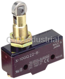
Omron X10GM Switch - BASIC SWITCH; Direct Current Switch with Built-in Magnetic Blowout
Part Number
X10GM
Price
Request Quote
Manufacturer
OMRON
Lead Time
Request Quote
Category
Switches
Datasheet

Extracted Text
General-purpose Basic Switch X CSM_X_DS_E_3_1 Direct Current Switch with Built-in Magnetic Blowout • Incorporates a small permanent magnet in the contact mechanism to deflect the arc to effectively extinguish it. Same shape and mounting procedures as the Z Basic Switches. Be sure to read Safety Precautions on page 6 and Safety Precautions for All Basic Switches. Model Number Structure Ordering Information Model Number Legend Terminal Solder terminal Screw terminal Actuator Model Model X-10G@-@ (1) (2)(3) (4) Pin plunger X-10G X-10G-B (1) Ratings Slim spring plunger X-10GS X-10GS-B 10 : 10 A (125 VDC) (2) Contact Gap Short spring plunger X-10GD X-10GD-B G : 0.9 mm Panel mount plunger X-10GQ X-10GQ-B (3) Actuator None : Pin plunger D : Short spring plunger Panel mount roller plunger X-10GQ22 X-10GQ22-B S : Slim spring plunger Panel mount cross Q : Panel mount plunger X-10GQ21 X-10GQ21-B roller plunger Q21 : Panel mount cross roller plunger Q22 : Panel mount roller plunger X-10GL X-10GL-B Leaf spring L : Leaf spring W : Hinge lever Short hinge lever X-10GW21 X-10GW21-B W2 : Hinge roller lever W21 : Short hinge lever W22 : Short hinge roller lever Hinge lever X-10GW X-10GW-B W4 : Low-force hinge lever M : Reverse hinge lever X-10GW4 X-10GW4-B Low-force hinge lever M2 : Reverse hinge roller lever M22 : Reverse short hinge roller lever Short hinge roller lever X-10GW22 X-10GW22-B (4) Terminals None : Solder terminal Hinge roller lever X-10GW2 X-10GW2-B B : Screw terminal (with toothed washer) X-10GM X-10GM-B Reverse hinge lever Reverse short hinge X-10GM22 X-10GM22-B roller lever * Reverse hinge roller lever * X-10GM2 X-10GM2-B * The plungers of reverse-type models are continuously pressed by the compression coil springs and the plungers are freed by operating the levers. Accessories (Terminal Covers, Actuators, and Separators): Refer to Z/A/X/DZ Common Accessories and Z/X/DZ Common Accessories. 1 X Specifications Ratings Contact Specification Non-inductive load (A) Inductive load (A) Material Silver Contacts Rated Resistive Inductive Gap Lamp load Motor load 0.9 mm voltage load load (standard value) NC NO NC NO NC NO NC NO NC 30 A max. Inrush current 8 VDC 10 3 1.5 10 10 5 2.5 NO 15 A max. 14 VDC 10 3 1.5 10 10 5 2.5 30 VDC 10 3 1.5 10 10 5 2.5 Engineering Data 125 VDC 10 3 1.5 7.5 6 5 2.5 Mechanical Durability (X-10G) 250 VDC 3 1.5 0.75 2 1.5 2 1.5 5,000 Note: 1. The above values are for the steady-state current. Ambient temperature: 20±2°C 3,000 2. Inductive load has a power factor of 0.4 min. (AC) and a time constant Ambient humidity: 65±5%RH of 7 ms max. (DC). Without load Operating frequency: 240 operations/min 3. Lamp load has an inrush current of 10 times the steady-state current. 1,000 4. Motor load has an inrush current of 6 times the steady-state current. 700 5. The above electrical ratings also apply to the AC voltage. 500 6. With the reverse-type models (X-10GM@), the normally closed circuits and normally open circuits are reversed. 300 7. The ratings values apply under the following test conditions: 200 (1) Ambient temperature: 20±2°C (2) Ambient humidity: 65±5%RH 100 (3) Operating frequency: 20 operations/min 70 50 Certified Standard Ratings 30 20 Ask your OMRON representative for information on certified models. UL/CSA 10 0 0.1 0.2 0.3 0.4 0.5 0.6 0.7 0.8 0.9 Rated voltage Model X-10G Overtravel (mm) 125 VDC 10 A Electrical Durability (X-10G) 250 VDC 3 A 500 Ambient temperature: 20±2°C EN (CE) (Conform to EN61058-1) 300 Ambient humidity: 65±5%RH 200 Operating frequency: 20 operations/min Rated voltage Model X-10 125 VDC 10 A 100 70 50 Characteristics 125 VDC L/R = 0 30 Operating speed 0.1 mm to 1 m/s *1 20 Mechanical 240 operations/min 125 VDC Operating L/R = 7 ms frequency Electrical 20 operations/min 10 7 Insulation resistance 100 MΩ min. (at 500 VDC) 5 Contact resistance 15 mΩ max. (initial value) 3 1,500 VAC, 50/60 Hz for 1 min between 2 terminals of the same polarity, between Dielectric strength current-carrying metal parts and the ground, 1 021 48610124 and between each terminal and non-current- Switching current (A) carrying metal parts Vibration Malfunction 10 to 55 Hz, 1.5-mm double amplitude *2 resistance 2 Destruction 1,000 m/s max. Shock 2 resistance Malfunction 300 m/s max. *1 *2 Mechanical 1,000,000 operations min. Durability Electrical 100,000 operations min. Degree of protection IP00 Degree of protection Class I against electric shock Proof tracking index (PTI) 175 Ambient operating −25°C to 80°C (with no icing) temperature Ambient operating 35% to 85%RH humidity Weight Approx. 27 to 63 g *1. The values are for the pin plunger models. (Contact your OMRON representative for other models.) *2. Malfunction: 1 ms max. Structure Contact Form (SPDT) (+) COM NC NO Note: With the reverse-type models (X-10GM@), the NC and NO terminal arrangements are reversed. 2 4 4 Durability (x10 operations) Durability (x10 operations) X Dimensions (Unit: mm) Terminals Mounting Use M4 mounting screws with plane washers or spring washers Screw Terminals (-B) to securely mount the Switch. Tighten the screws to a torque of 1.18 to 1.47 N·m. Two, 4.2-dia. mounting 9.2 holes or M4 screw holes 20 20 ±0.2 17.45 ±0.1 25.4 COM NO NC The Switch can be panel mounted, provided that the hexagonal Three, M4 × 5.5 Terminal screws 13 2 nut of the actuator is tightened to a torque of 2.94 to 4.9 N·m. (with toothed 49.2 washer) Panel Mount Plunger Panel Mount Roller Plunger Solder Terminal (-A) ("-A" is not included in the model numbers.) +0.2 +0.2 12.5 dia. 12.5 dia. 0 0 +0.2 5 0 6.4 +0.2 ±0.1 25.4 13 0 11.9 ±0.2 17.45 3 1 NO COM NC 2 49.2 Note: 1. Tighten the terminal screws to a torque of 0.78 to 1.18 N·m. 2. Unless otherwise specified, a tolerance of ±0.4 mm applies to all dimensions. 3. In case of DC voltage, set the COM to the positive terminal. 3 X Dimensions and Operating Characteristics The models, illustrations, and graphics are for screw-terminal models. (The dimensions for models that are omitted here are the same as for pin-plunger models.) Pin Plunger Slim Spring Plunger X-10G-B X-10GS-B 5.2 dia. PT 23.3±0.25 4 dia. 2.3 dia. *1 PT ±0.25 +0.075 2.3SR *1 23.3 4.2 dia. hole -0.025 *2 *2 OP OP 24.2 9 dia. 24.2 9.2 +0.075 4.2 -0.025 +0.1 4.36 dia. -0.05 ±0.2 17.45 11.9 25.4±0.1 *1. Stainless-steel pin plunger (flat, 1R chamfering) *1. Stainless-steel pin plunger *2. Three vent holes 49.2 *2. Three vent holes Short Spring Plunger Panel Mount Plunger X-10GD-B X-10GQ-B 8.35 dia. PT ±0.25 23.3 12.3 dia. M12 × 1 mounting screw 11.9SR *1 Two hexagonal nuts 10 dia. (2 t × 14 width PT ±0.25 23.3 7.15 dia. OP across flats) *3 12SR *1 13.1 *2 Two lock nuts (2 t × 15.6 width OP across flats) 16 dia. 16.3 *2 24.2 *1. Stainless-steel pin plunger *1. Plated iron plunger *2. Three vent holes *2. Three vent holes *3. Incomplete screw part with a maximum length of 1.5 mm Note: Do not use both the M12 mounting screw and the mounting holes in the case at the same time. Doing so will cause stress to be applied to the Switch, possibly damaging the case or cover. Panel Mount Roller Plunger Panel Mount Cross Roller Plunger X-10GQ22-B X-10GQ21-B 12.7 dia. × 4.8 *1 12.7 dia. × 4.8 *1 PT ±0.25 PT 23.3±0.25 23.3 M12 × 1 mounting screw M12 × 1 mounting screw Two hexagonal nuts Two hexagonal nuts OP OP (3 t × 17 width (3 t × 17 width across flats) across flats) 15.5 15.5 *3 *3 *2 *2 16 dia. 16 dia. 16.3 16.3 *1. Stainless-steel roller *1. Stainless-steel roller *2. Three vent holes *2. Three vent holes *3. Incomplete screw part with a maximum length of 1.5 mm. *3. Incomplete screw part with a maximum length of 1.5 mm. Note: Do not use both the M12 mounting screw and the mounting holes in the Note: Do not use both the M12 mounting screw and the mounting holes in the case at the same time. Doing so will cause stress to be applied to the case at the same time. Doing so will cause stress to be applied to the Switch, possibly damaging the case or cover. Switch, possibly damaging the case or cover. Leaf Spring t = 0.3 *1 X-10GL-B 4.8 ±0.8 49.6 *2 FP OP *1. Stainless-steel spring lever *2. Three vent holes Note: Unless otherwise specified, a tolerance of ±0.4 mm applies to all dimensions. Operating Characteristics Model X-10G-B X-10GS-B X-10GD-B X-10GQ-B X-10GQ22-B X-10GQ21-B X-10GL-B Operating force OF max. 5.00 N 5.00 N 5.00 N 5.00 N 5.00 N 5.00 N 1.96 N Release force RF min. 1.12 N 1.12 N 1.12 N 1.12 N 1.12 N 1.12 N 0.14 N Pretravel PT max. 0.9 mm 0.9 mm 0.9 mm 0.9 mm 0.9 mm 0.9 mm − Overtravel OT min. 0.13 mm 1.6 mm 1.6 mm 5.5 mm 3.6 mm 3.6 mm 1.6 mm * Movement Differential MD max. 0.18 mm 0.18 mm 0.18 mm 0.18 mm 0.18 mm 0.18 mm 2.3 mm Free Position FP max. − − − − − − 22.1 mm Operating Position OP 15.9±0.4 mm 28.2±0.5 mm 21.2±0.5 mm 21.8±0.8 mm 33.4±1.2 mm 33.4±1.2 mm 17.4±0.8 mm * Be sure to use the switch at the rated OT value of 1.6 mm. 4 X Short Hinge Lever Hinge Lever X-10GW21-B X-10GW-B t = 1 *1 26.2 4.9 t = 1 *1 4.9 26.2 *2 *2 FP FP OP 20.2 17.4 20.2 OP 14.4 17.4 14.4 9.2 +0.075 4.2 -0.025 +0.075 4.2 dia. holes -0.025 +0.1 4.36 dia. -0.05 ±0.2 17.45 *1. Stainless-steel lever 11.9 ±0.1 *2. Three vent holes 25.4 *1. Stainless-steel lever 49.2 *2. Three vent holes Low-force Hinge Lever Short Hinge Roller Lever X-10GW4-B X-10GW22-B 9.5 dia. × 4 t = 1 *1 plastic roller 26.2 t = 1 *1 4.9 26.2 PT *2 *2 FP OP OP 20.2 20.2 17.4 17.4 14.4 14.4 *1. Stainless-steel lever *1. Stainless-steel spring lever *2. Three vent holes *2. Three vent holes Hinge Roller Lever Reverse Hinge Lever X-10GW2-B X-10GM-B 9.5 dia. × 4 plastic roller 26.2 t = 1 *1 *1 4.9 t = 1 18.65 *2 *2 FP OP FP 20.2 OP 20.2 17.4 17.4 14.4 14.4 *1. Stainless-steel lever *1. Stainless-steel lever *2. Three vent holes *2. Three vent holes Reverse Short Hinge Lever Reverse Hinge Roller Lever X-10GM22-B X-10GM2-B 9.5 dia. × 4 t = 1*1 plastic roller 9.5 dia. × 4 18.65 plastic roller 18.65 *1 *2 *2 t = 1 FP OP FP OP 20.2 17.4 14.4 20.2 17.4 14.4 *1. Stainless-steel lever *2. Three vent holes *1. Stainless-steel lever *2. Three vent holes Note: Unless otherwise specified, a tolerance of ±0.4 mm applies to all dimensions. Model Operating X-10GW21-B X-10GW-B X-10GW4-B X-10GW22-B X-10GW2-B X-10GM-B X-10GM22-B X-10GM2-B Characteristics OF max. 2.45 N 1.08 N 0.25 N 2.16 N 1.42 N 2.16 N 6.86 N 3.14 N RF min. 0.31 N 0.14 N 0.05 N 0.34 N 0.21 N 0.25 N 1.52 N 0.49 N PT max. − − 14.3 mm − − − − − OT min. 2.1 mm 4.8 mm 4.8 mm 2.4 mm 4 mm 5.5 mm 2 mm 4 mm MD max. 1.7 mm 3.9 mm 3.9 mm 1.7 mm 3 mm 2.1 mm 0.75 mm 1.5 mm FP max. 25.5 mm 34.6 mm − 37.1 mm 40.5 mm 26.8 mm 36.1 mm 37.4 mm OP 20.7±0.8 mm 21.1±0.8 mm 21.1±0.8 mm 32.2±0.8 mm 32.2±0.8 mm 21.1±0.8 mm 32.2±0.8 mm 32.2±0.8 mm 5 63.5R 63.5R 56R 28.2R 48.5R 40.6R 26.6R 18.5R X Safety Precautions Refer to Safety Precautions for All Basic Switches. • Do not use the switch outside the specified temperature and Precautions for Safe Use atmospheric conditions. The permissible ambient temperature depends on the model. Terminal Connection (Refer to the specifications in this catalog.) Sudden thermal When soldering lead wires to the Switch, make sure that the capacity changes may cause thermal shock to distort the switch and result of the soldering iron is 60 W maximum. Do not take more than 5 s to in faults. solder any part of the Switch. The characteristics of the Switch will deteriorate if a soldering iron with a capacity of more than 60 W is Incorrect Correct Separate the installation lo- applied to any part of the Switch for 5 s or more. cation from heat sources. Operation • Make sure that the switching frequency or speed is within the specified range. 1.If the switching speed is extremely slow, the contact may not be switched smoothly, which may result in a contact failure or • Mount a cover if the switch is to be installed in a location where contact welding. worker inattention could result in incorrect operation or accidents. 2.If the switching speed is extremely fast, switching shock may Correct Incorrect damage the Switch soon. If the switching frequency is too high, the contact may not catch up with the speed. The rated permissible switching speed and frequency indicate the switching reliability of the Switch. The life of a Switch is determined at the specified switching speed. (preventing malfunctions) The life varies with the switching speed and frequency even when • Subjecting the switch to continuous vibration or shock may result in they are within the permissible ranges. In order to determine the contact failure or faulty operation due to abrasion powder and in life of a Switch model to be applied to a particular use, it is best to reduced durability. Excessive vibration or shock will cause the conduct an appropriate durability test on some samples of the contacts to operate malfunction or become damaged. Mount the model under actual conditions. switch in a location that is not subject to vibration or shock and in a • Make sure that the actuator travel does not exceed the permissible direction that does not subject the switch to resonance. OT position. The operating stroke must be set to 70% to 100% of • If silver contacts are used with relatively low frequency for a long the rated OT. time or are used with microloads, the sulfide coating produced on the contact surface will not be broken down and contact faults will Precautions for Correct Use result. Use a microload switch that uses gold contacts. • Do not use the switch in atmospheres with high humidity or heat or Mounting Location in harmful gases, such as sulfide gas (H2S, SO2), ammonia gas • Do not use the switch alone in atmospheres such as flammable or (NH3), nitric acid gas (HNO3), or chlorine gas (Cl2). Doing so may explosive gases. Arcing and heat generation associated with impair functionality, such as with damage due to contacting faults switching may cause fires or explosions. or corrosion. • Switches are generally not constructed with resistance against • The switch includes contacts. If the switch is used in an atmosphere water. Use a protective cover to prevent direct spraying if the switch with silicon gas, arc energy may cause silicon oxide (SiO2) to is used in locations subject to splashing or spurting oil or water, dust accumulate on the contacts and result in contact failure. If there is adhering. silicon oil, silicon filling, silicon wiring, or other silicon products in the Incorrect Correct vicinity of the switch, use a contact protection circuit to limit arcing and remove the source of the silicon gas. Handling • Set the common (COM) terminal to the positive terminal. If it is set to the negative terminal, the Switch will not turn OFF. Terminal box Terminal box • When using the Switch under an inductive load, the arc suppression capability varies depending on current. If the current • Install the switch in a location that is not directly subject to debris becomes 0.6 to 1.2 A or of the time constant L/R exceeds 7 ms, be and dust from cutting. The actuator and the switch body must be sure to provide an arc suppressor. protected from accumulated cutting debris and dirt. • Since the Switch incorporates a permanent magnet, attention must Incorrect Correct be paid to the following points: (a) Avoid mounting the Switch directly onto a magnetic substance. (b) Do not subject the Switch to severe shocks. (c) Avoid placing the Switch in a strong magnetic field. • Do not use the switch in locations subject to hot water (greater than (d) Be sure to prevent iron dust or iron chips from adhering to the 60°C) or in water vapor. built-in magnet or the magnetic blowout function of the Switch will be adversely affected. (e) Do not apply thermal shock to the Switch, or the magnetic flux will be diminished. • Since a ventilation hole is provided to avoid abnormal corrosion due to operating conditions, provide a dustproofing device in locations where the Switch is exposed to dust. 6 X • Do not change operating positions for the actuator. Changing the position may cause malfunction. Panel-mounted Model (X-10GQ@) • To side-mount the panel-mount Switch to the panel with screws, remove the hexagonal nut from the actuator. • Too large a dog angle and too fast operating speed may damage the Switch when the Switch is side-mounted on the panel. • Too fast operating speed and too long overtravel of the roller plunger Switch may result in damage to the Switch. Accessories (Order separately) Refer to Z/A/X/DZ Common Accessories for details about Terminal Covers, Separators, and Actuators. 7 Read and Understand This Catalog Please read and understand this catalog before purchasing the products. Please consult your OMRON representative if you have any questions or comments. Warranty and Limitations of Liability WARRANTY OMRON's exclusive warranty is that the products are free from defects in materials and workmanship for a period of one year (or other period if specified) from date of sale by OMRON. OMRON MAKES NO WARRANTY OR REPRESENTATION, EXPRESS OR IMPLIED, REGARDING NON-INFRINGEMENT, MERCHANTABILITY, OR FITNESS FOR PARTICULAR PURPOSE OF THE PRODUCTS. ANY BUYER OR USER ACKNOWLEDGES THAT THE BUYER OR USER ALONE HAS DETERMINED THAT THE PRODUCTS WILL SUITABLY MEET THE REQUIREMENTS OF THEIR INTENDED USE. OMRON DISCLAIMS ALL OTHER WARRANTIES, EXPRESS OR IMPLIED. LIMITATIONS OF LIABILITY OMRON SHALL NOT BE RESPONSIBLE FOR SPECIAL, INDIRECT, OR CONSEQUENTIAL DAMAGES, LOSS OF PROFITS OR COMMERCIAL LOSS IN ANY WAY CONNECTED WITH THE PRODUCTS, WHETHER SUCH CLAIM IS BASED ON CONTRACT, WARRANTY, NEGLIGENCE, OR STRICT LIABILITY. In no event shall the responsibility of OMRON for any act exceed the individual price of the product on which liability is asserted. IN NO EVENT SHALL OMRON BE RESPONSIBLE FOR WARRANTY, REPAIR, OR OTHER CLAIMS REGARDING THE PRODUCTS UNLESS OMRON'S ANALYSIS CONFIRMS THAT THE PRODUCTS WERE PROPERLY HANDLED, STORED, INSTALLED, AND MAINTAINED AND NOT SUBJECT TO CONTAMINATION, ABUSE, MISUSE, OR INAPPROPRIATE MODIFICATION OR REPAIR. Application Considerations SUITABILITY FOR USE OMRON shall not be responsible for conformity with any standards, codes, or regulations that apply to the combination of products in the customer's application or use of the products. At the customer's request, OMRON will provide applicable third party certification documents identifying ratings and limitations of use that apply to the products. This information by itself is not sufficient for a complete determination of the suitability of the products in combination with the end product, machine, system, or other application or use. The following are some examples of applications for which particular attention must be given. This is not intended to be an exhaustive list of all possible uses of the products, nor is it intended to imply that the uses listed may be suitable for the products: · Outdoor use, uses involving potential chemical contamination or electrical interference, or conditions or uses not described in this catalog. · Nuclear energy control systems, combustion systems, railroad systems, aviation systems, medical equipment, amusement machines, vehicles, safety equipment, and installations subject to separate industry or government regulations. · Systems, machines, and equipment that could present a risk to life or property. Please know and observe all prohibitions of use applicable to the products. NEVER USE THE PRODUCTS FOR AN APPLICATION INVOLVING SERIOUS RISK TO LIFE OR PROPERTY WITHOUT ENSURING THAT THE SYSTEM AS A WHOLE HAS BEEN DESIGNED TO ADDRESS THE RISKS, AND THAT THE OMRON PRODUCTS ARE PROPERLY RATED AND INSTALLED FOR THE INTENDED USE WITHIN THE OVERALL EQUIPMENT OR SYSTEM. PROGRAMMABLE PRODUCTS OMRON shall not be responsible for the user's programming of a programmable product, or any consequence thereof. Disclaimers CHANGE IN SPECIFICATIONS Product specifications and accessories may be changed at any time based on improvements and other reasons. It is our practice to change model numbers when published ratings or features are changed, or when significant construction changes are made. However, some specifications of the products may be changed without any notice. When in doubt, special model numbers may be assigned to fix or establish key specifications for your application on your request. Please consult with your OMRON representative at any time to confirm actual specifications of purchased products. DIMENSIONS AND WEIGHTS Dimensions and weights are nominal and are not to be used for manufacturing purposes, even when tolerances are shown. PERFORMANCE DATA Performance data given in this catalog is provided as a guide for the user in determining suitability and does not constitute a warranty. It may represent the result of OMRON’s test conditions, and the users must correlate it to actual application requirements. Actual performance is subject to the OMRON Warranty and Limitations of Liability. ERRORS AND OMISSIONS The information in this document has been carefully checked and is believed to be accurate; however, no responsibility is assumed for clerical, typographical, or proofreading errors, or omissions. 2009.11 In the interest of product improvement, specifications are subject to change without notice. OMRON Corporation Industrial Automation Company http://www.ia.omron.com/ (c)Copyright OMRON Corporation 2009 All Right Reserved.
Frequently asked questions
How does Industrial Trading differ from its competitors?

Is there a warranty for the X10GM?
Which carrier will Industrial Trading use to ship my parts?
Can I buy parts from Industrial Trading if I am outside the USA?
Which payment methods does Industrial Trading accept?


What they say about us
FANTASTIC RESOURCE
One of our top priorities is maintaining our business with precision, and we are constantly looking for affiliates that can help us achieve our goal. With the aid of GID Industrial, our obsolete product management has never been more efficient. They have been a great resource to our company, and have quickly become a go-to supplier on our list!
Bucher Emhart Glass
EXCELLENT SERVICE
With our strict fundamentals and high expectations, we were surprised when we came across GID Industrial and their competitive pricing. When we approached them with our issue, they were incredibly confident in being able to provide us with a seamless solution at the best price for us. GID Industrial quickly understood our needs and provided us with excellent service, as well as fully tested product to ensure what we received would be the right fit for our company.
Fuji
HARD TO FIND A BETTER PROVIDER
Our company provides services to aid in the manufacture of technological products, such as semiconductors and flat panel displays, and often searching for distributors of obsolete product we require can waste time and money. Finding GID Industrial proved to be a great asset to our company, with cost effective solutions and superior knowledge on all of their materials, it’d be hard to find a better provider of obsolete or hard to find products.
Applied Materials
CONSISTENTLY DELIVERS QUALITY SOLUTIONS
Over the years, the equipment used in our company becomes discontinued, but they’re still of great use to us and our customers. Once these products are no longer available through the manufacturer, finding a reliable, quick supplier is a necessity, and luckily for us, GID Industrial has provided the most trustworthy, quality solutions to our obsolete component needs.
Nidec Vamco
TERRIFIC RESOURCE
This company has been a terrific help to us (I work for Trican Well Service) in sourcing the Micron Ram Memory we needed for our Siemens computers. Great service! And great pricing! I know when the product is shipping and when it will arrive, all the way through the ordering process.
Trican Well Service
GO TO SOURCE
When I can't find an obsolete part, I first call GID and they'll come up with my parts every time. Great customer service and follow up as well. Scott emails me from time to time to touch base and see if we're having trouble finding something.....which is often with our 25 yr old equipment.
ConAgra Foods