

 Manufacturers
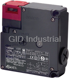
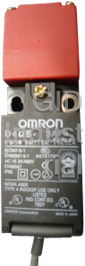
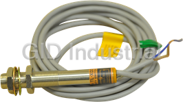
OMRON D4NL
Description
Omron D4NL Series Guard Lock Safety-door Switches
Part Number
D4NL
Price
Request Quote
Manufacturer
OMRON
Lead Time
Request Quote
Category
Switches
Features
- Built-in switches with multiple-contact construction are available.
- Can be used for either standard loads or microloads.
- IP67 degree of protection.
- Key holding force of 1,300 N minimum.
- Lineup includes models with a conduit size of M20.
- Selectable Operation Key insertion direction and adjustable mounting ensure installation flexibility.
- Variety of Metallic Heads Available.
Datasheet

Extracted Text
Guard Lock Safety-door Switch D4NL CSM_D4NL_DS_E_3_1 Best-selling Guard Lock Safety-door Switch Available in Several Compact, Multi-contact Models • Selectable Operation Key insertion direction and adjustable mounting ensure installation flexibility. Built-in switches with multip le-contact construction are available. Key holding force of 1,300 N minimum. Can be used for either standard loads or microloads. Lineup includes models with a conduit size of M20. IP67 degree of protection. Variety of Metallic Heads Available. Be sure to read the “Safety Precautions” on page 15 and the “Precautions for All Safety Door Switches”. Model Number Structure Model Number Legend Switch Operation Key \ D4NL-@@@@-@@@ D4DS-K@ 12 3 4 5 6 7 1 1. Conduit Size 1. Operation Key Type 1: Pg13.5 1: Horizontal mounting 2: G1/2 2: Vertical mounting 4: M20 * 3: Adjustable mounting (horizontal) 2. Built-in Switch (with Door Open/Closed Detection Switch and 5: Adjustable mounting (horizontal/vertical) Lock Monitor Switch Contacts) A: 1NC/1NO (slow-action contacts) + 1NC/1NO (slow-action contacts) B: 1NC/1NO (slow-action contacts) + 2NC (slow-action contacts) C: 2NC (slow-action contacts) + 1NC/1NO (slow-action contacts) D: 2NC (slow-action contacts) + 2NC (slow-action contacts) E: 2NC/1NO (slow-action contacts) + 1NC/1NO (slow-action contacts) F: 2NC/1NO (slow-action contacts) + 2NC (slow-action contacts) G: 3NC (slow-action contacts) + 1NC/1NO (slow-action contacts) H: 3NC (slow-action contacts) + 2NC (slow-action contacts) 3. Head Mounting Direction and Material F: Four mounting directions possible (Front-side mounting at shipping)/plastic D: Four mounting directions possible (Front-side mounting at shipping)/metal 4. Door Lock and Release A: Mechanical lock/24 VDC solenoid release B: Mechanical lock/110 VAC solenoid release C: Mechanical lock/230 VAC solenoid release G: 24 VDC solenoid lock/mechanical release H: 110 VAC solenoid lock/mechanical release J: 230 VAC solenoid lock/mechanical release 5. Indicator B: 10 to 115 VAC/VDC (orange LED indicator) 6. Release Key Type Blank: Standard 4: Special release key (Note: Release keys are provided.) 7. Release Key Position Blank: Bottom S: Front * Models with M20 conduits are also available with an M20 to 1/2-14NPT Adaptor. 1 D4NL Ordering Information List of Models Switches (Operation Keys are sold separately.) : Models with certified direct opening contacts. Consult with your OMRON representative when ordering any models that are not listed in this table. Contact configuration (door open/closed Release detection switch and lock Head Release Solenoid voltage/ Lock and release key monitor switch contacts) Conduit opening Model material key type indicator types position (slow-action) Certified direct opening NC contact Pg13.5 D4NL-1AFA-B 1NC/1NO+1NC/1NO G1/2 D4NL-2AFA-B M20 D4NL-4AFA-B Pg13.5 D4NL-1BFA-B 1NC/1NO+2NC G1/2 D4NL-2BFA-B M20 D4NL-4BFA-B Pg13.5 D4NL-1CFA-B 2NC+1NC/1NO G1/2 D4NL-2CFA-B M20 D4NL-4CFA-B Pg13.5 D4NL-1DFA-B 2NC+2NC G1/2 D4NL-2DFA-B M20 D4NL-4DFA-B Mechanical lock Solenoid release Pg13.5 D4NL-1EFA-B 2NC/1NO+1NC/1NO G1/2 D4NL-2EFA-B M20 D4NL-4EFA-B Pg13.5 D4NL-1FFA-B 2NC/1NO+2NC G1/2 D4NL-2FFA-B M20 D4NL-4FFA-B Pg13.5 D4NL-1GFA-B 3NC+1NC/1NO G1/2 D4NL-2GFA-B M20 D4NL-4GFA-B Pg13.5 D4NL-1HFA-B 3NC+2NC G1/2 D4NL-2HFA-B Solenoid: 24 VDC M20 D4NL-4HFA-B Plastic * Bottom Standard Orange LED: 10 to 115 Pg13.5 D4NL-1AFG-B VAC/VDC 1NC/1NO+1NC/1NO G1/2 D4NL-2AFG-B M20 D4NL-4AFG-B Pg13.5 D4NL-1BFG-B 1NC/1NO+2NC G1/2 D4NL-2BFG-B M20 D4NL-4BFG-B Pg13.5 D4NL-1CFG-B 2NC+1NC/1NO G1/2 D4NL-2CFG-B M20 D4NL-4CFG-B Pg13.5 D4NL-1DFG-B 2NC+2NC G1/2 D4NL-2DFG-B M20 D4NL-4DFG-B Solenoid lock Mechanical release Pg13.5 D4NL-1EFG-B 2NC/1NO+1NC/1NO G1/2 D4NL-2EFG-B M20 D4NL-4EFG-B Pg13.5 D4NL-1FFG-B 2NC/1NO+2NC G1/2 D4NL-2FFG-B M20 D4NL-4FFG-B Pg13.5 D4NL-1GFG-B 3NC+1NC/1NO G1/2 D4NL-2GFG-B M20 D4NL-4GFG-B Pg13.5 D4NL-1HFG-B 3NC+2NC G1/2 D4NL-2HFG-B M20 D4NL-4HFG-B * Switches with metal heads can also be manufactured upon request. Ask your OMRON representative for details. 2 D4NL Contact configuration (door open/closed Release detection switch and lock Head Release Solenoid voltage/ Lock and release key monitor switch contacts) Conduit opening Model material key type indicator types position (slow-action) Certified direct opening NC contact Pg13.5 D4NL-1AFA-B4 1NC/1NO+1NC/1NO G1/2 D4NL-2AFA-B4 M20 D4NL-4AFA-B4 Pg13.5 D4NL-1BFA-B4 1NC/1NO+2NC G1/2 D4NL-2BFA-B4 M20 D4NL-4BFA-B4 Pg13.5 D4NL-1CFA-B4 2NC+1NC/1NO G1/2 D4NL-2CFA-B4 M20 D4NL-4CFA-B4 Pg13.5 D4NL-1DFA-B4 2NC+2NC G1/2 D4NL-2DFA-B4 M20 D4NL-4DFA-B4 Mechanical lock Solenoid release Pg13.5 D4NL-1EFA-B4 2NC/1NO+1NC/1NO G1/2 D4NL-2EFA-B4 *2 M20 D4NL-4EFA-B4 Pg13.5 D4NL-1FFA-B4 2NC/1NO+2NC G1/2 D4NL-2FFA-B4 *2 M20 D4NL-4FFA-B4 Pg13.5 D4NL-1GFA-B4 3NC+1NC/1NO G1/2 D4NL-2GFA-B4 *2 M20 D4NL-4GFA-B4 Pg13.5 D4NL-1HFA-B4 3NC+2NC G1/2 D4NL-2HFA-B4 *2 Special Solenoid: 24 VDC M20 D4NL-4HFA-B4 Plastic *1Bottom release Orange LED: 10 to 115 Pg13.5 D4NL-1AFG-B4 key VAC/VDC 1NC/1NO+1NC/1NO G1/2 D4NL-2AFG-B4 M20 D4NL-4AFG-B4 Pg13.5 D4NL-1BFG-B4 1NC/1NO+2NC G1/2 D4NL-2BFG-B4 M20 D4NL-4BFG-B4 Pg13.5 D4NL-1CFG-B4 2NC+1NC/1NO G1/2 D4NL-2CFG-B4 M20 D4NL-4CFG-B4 Pg13.5 D4NL-1DFG-B4 2NC+2NC G1/2 D4NL-2DFG-B4 M20 D4NL-4DFG-B4 Solenoid lock Mechanical release Pg13.5 D4NL-1EFG-B4 2NC/1NO+1NC/1NO G1/2 D4NL-2EFG-B4 M20 D4NL-4EFG-B4 Pg13.5 D4NL-1FFG-B4 2NC/1NO+2NC G1/2 D4NL-2FFG-B4 M20 D4NL-4FFG-B4 Pg13.5 D4NL-1GFG-B4 3NC+1NC/1NO G1/2 D4NL-2GFG-B4 M20 D4NL-4GFG-B4 Pg13.5 D4NL-1HFG-B4 3NC+2NC G1/2 D4NL-2HFG-B4 M20 D4NL-4HFG-B4 *1. Switches with metal heads can also be manufactured upon request. Ask your OMRON representative for details. *2. Models with Korean S-mark certification. 3 D4NL Operation Keys Type Model Horizontal mounting D4DS-K1 Vertical mounting D4DS-K2 Adjustable mounting (Horizontal) D4DS-K3 Adjustable mounting (Horizontal/Vertical) D4DS-K5 Specifications Standards and EC Directives Certified Standard Ratings Conforms to the following EC Directives: TÜV (EN60947-5-1), CCC (GB14048.5) • Machinery Directive Utilization AC-15 DC-13 • Low Voltage Directive Item category • EN 1088 Rated operating current (Ie) 3 A 0.27 A • EN 60204-1 Rated operating voltage (Ue) 240 V 250 V • GS-ET-19 Note: Use a 10 A fuse type gI or gG that conforms to IEC60269 as a Certified Standards short-circuit protection device. This fuse is not built into the Switch. Certification body Standard File No. Consult your UL/CSA (UL508, CSA C22.2 No. 14) EN60947-5-1 OMRON TÜV SÜD A300 (certified direct opening) representative for details. Current (A) Volt-amperes (VA) Rated Carry current UL *1 UL508, CSA C22.2 No.14 E76675 voltage Make Break Make Break CQC (CCC) GB14048.5 2003010305064267 120 VAC 60 6 10 A 7,200 720 KOSHA *2 EN60947-5-1 2005-196 240 VAC 30 3 *1. Certification for CSA C22.2 No. 14 is authorized by the UL mark. Q300 *2. Only certain models have been certified. Current (A) Volt-amperes (VA) Rated Carry current voltage Make Break Make Break 125 VDC 0.55 0.55 2.5 A 69 69 250 VDC 0.27 0.27 Solenoid Coil Characteristics Item Type 24 VDC 110 VAC 230 VAC Rated operating +10% voltage 24 VDC −15% 110 VAC ±10% 230 VAC ±10% (100% ED) Current Approx. 200 mA Approx. 50 mA Approx. 30 mA consumption Insulation Class F (130°C max.) Indicator Characteristics Item Type LED Rated voltage 10 to 115 VAC/VDC Current leakage Approx. 1 mA Color (LED) Orange 4 D4NL Characteristics Degree of protection *1 IP67 (EN60947-5-1) Mechanical 1,000,000 operations min. Durability *2 Electrical 500,000 operations min. (3 A resistive load at 250 VAC) *3 Operating speed 0.05 to 0.5 m/s Operating frequency 30 operations/minute max. Direct opening force *4 60 N min. (EN60947-5-1) Direct opening travel *4 10 mm min. (EN60947-5-1) Holding force *5 1,300 N min. Contact resistance 25 mΩ max. (per contact) Minimum applicable load *6 1 mA resistive load at 5 VDC (N-level reference value) Rated insulation voltage (Ui) 300 V (EN60947-5-1) Rated frequency 50/60 Hz Protection against electric shock Class II (double insulation) Pollution degree (operating environment) 3 (EN60947-5-1) Between terminals of 2.5 kV same polarity Between terminals of Impulse withstand 4 kV different polarity voltage Between each (EN60947-5-1) terminal and 6 kV non-current carrying metallic parts Insulation resistance 100 MΩ min. (at 500 VDC) Contact gap 2 × 2 mm min. Vibration Malfunction 10 to 55 Hz, 0.75 mm single amplitude resistance 2 Destruction 1,000 m/s min. Shock resistance 2 Malfunction 100 m/s min. Conditional short-circuit current 100 A (EN60947-5-1) Conventional free air thermal current (Ith) 10 A (EN60947-5-1) Ambient operating temperature −10 to 55°C (with no icing) Ambient operating humidity 95% max. Weight Approx. 370 g (D4NL-1AFA-B) Note: 1. The above values are initial values. 2. The Switch contacts can be used with either standard loads or microloads. Once the contacts have been used to switch a load, however, they cannot be used to switch smaller loads. The contact surfaces will become rough once they have been used and contact reliability for smaller loads may be reduced. *1. The degree of protection is tested using the method specified by the standard (EN60947-5-1). Confirm that sealing properties are sufficient for the operating conditions and environment beforehand. Although the switch box is protected from dust or water penetration, do not use the D4NL in places where foreign material may enter through the key hole on the head, otherwise Switch damage or malfunctioning may occur. *2. The durability is for an ambient temperature of 5 to 35°C and an ambient humidity of 40% to 70%. For more details, consult your OMRON representative. *3. Do not pass the 3 A, 250 VAC load through more than 2 circuits. *4. These figures are minimum requirements for safe operation. *5. This figure is based on the GS-ET-19 evaluation method. *6. This value will vary with the switching frequency, environment, and reliability level. Confirm that correct operation is possible with the actual load beforehand. 5 D4NL Connections Internal Circuit Diagram Circuit Connection Example Indicator Connection Example for D4NL-@F@@-B • Terminals 12 and 41 are connected internally. When connecting 10 to 115 VAC/VDC R inputs to safety circuits, use terminals 11 and 42. (GS-ET-19). • Connect terminals 21 and 22 and terminals 51 and 52 in series when using as safety-circuit inputs (redundancy circuit for ZD LED terminals 11 and 12 and terminals 41 and 42 below). Connect the R terminals individually when using as auxiliary-circuit inputs (e.g., terminals 21 and 22 for safety-door open/closed monitoring and Constant-current diode terminals 51 and 52 for monitoring the lock status). • In the following connection example, terminals 21 and 22 and Solenoid terminals 51 and 52 are used as auxiliary-circuit inputs. • Direct opening contacts used as safety-circuit inputs are indicated 24 VDC 110 VAC/230 VAC with the mark. Terminals 11 and 42, and terminals 21 and 22 E1 (+) E1 (+) have direct opening contacts. • Connect the indicators in parallel to the auxiliary circuits or E2 (−) terminals E1 and E2 (D4NL-@@@A-B, -@@@G-B, -@@@B-B, and E2 (−) -@@@H-B only). Connecting to contacts with direct opening mechanisms may result in short-circuit current flowing if the indicator is destroyed, possibly resulting in incorrect equipment operation. • Do not switch circuits for two or more standard loads at the same time. Doing so may adversely affect insulation performance. • DC solenoids have polarity. Confirm terminal polarity before wiring. 51 12 41 42 Safety 11 circuit 52 Auxiliary 21 circuit 22 Auxiliary circuit 34 Auxiliary 33 circuit E2 (−) E1 (+) Indicator (Orange) O1 O2 6 D4NL Operation Method Operation Principles Solenoid Operation Key OFF ON OFF Mechanical lock models When the Operation Key is inserted, it is The solenoid is released only when the Spring locked by the lock spring. The door will lock is turned ON. Lock plate stay locked even if there is a power interruption. Solenoid Operation Key OFF ON Plunger OFF Solenoid lock models If the solenoid is OFF, the door will not be The door is locked only when the solenoid Spring locked when the Operation Key is is turned ON. This means that the door will Lock plate inserted. This means that the door can be be unlocked if there is a power interruption opened and closed easily when replacing and so this model cannot be used in workpieces or parts. systems that would maintain a hazardous state (e.g., systems requiring toxic gases, high temperatures, or gears that would continue to turn due to inertia). Structure and Nomenclature Structure Operation key hole Solenoid Terminal 42 Back-mounting is also possible. The head can be mounted in 4 directions. Terminal 41 Terminal E1 (+) Shorting pin (12-41) Terminal E2 (−) Terminal 01 Terminal 12 Indicator Terminal 11 Two conduits Terminal 02 Door open/closed (horizontal and vertical) detection switch Lock monitor switch Terminal 21 Conduit opening Special release key Terminal 22 (horizontal) Terminal 31/33 Standard Release Key Special Release Key Terminal 32/34 Terminal 52/54 (Bottom View) (Bottom View) Release key Terminal 51/53 Conduit opening (vertical) UNLOCK LOCK UNLOCK LOCK Note: Terminal numbers vary with the model. 7 D4NL Contact Form Indicates conditions where the Key is inserted and the lock is applied. Terminals 12 and 41 are connected internally (as per GS-ET-19). Contact form Contact (door open/closed Door open/ Model Operating pattern Remarks Lock detection and lock closed monitor monitor) detection Lock position Only NC contacts 11-12 Door open/ Lock monitor 11-42 have a certified direct closed detection 33-34 ON Zb Zb opening mechanism. D4NL-@AF@-@ 1NC/1NO + 1NC/1NO 53-54 11 12 41 42 The terminals 11-42, Stroke 33-34, and 53-54 can be Extraction Operation 33 34 53 54 completion Key insertion used as unlike poles. completion position position Lock position Only NC contacts 11-12 Door open/ Lock monitor 11-42 have a certified direct closed detection 33-34 ON Zb Zb opening mechanism. D4NL-@BF@-@ 1NC/1NO + 2NC 11 12 41 42 51-52 The terminals 11-42, Stroke 33-34, and 51-52 can be Operation 33 34 51 52 Extraction Key insertion completion used as unlike poles. completion position position Lock position Only NC contacts 11-12 Door open/ Lock monitor and 31-32 have a 11-42 closed detection certified direct opening 31-32 ON Zb Zb D4NL-@CF@-@ 2NC + 1NC/1NO mechanism. 11 12 41 42 53-54 Stroke The terminals 11-42, Operation Extraction 31 32 53 54 31-32, and 53-54 can be Key insertion completion completion position position used as unlike poles. Lock position Only NC contacts 11-12 and 31-32 have a Door open/ Lock monitor 11-42 11-42 closed detection certified direct opening 31-32 ON Zb Zb mechanism. D4NL-@DF@-@ 2NC + 2NC 11 12 41 42 51-52 51-52 The terminals 11-42, Stroke Operation Extraction 31 32 51 52 31-32, and 51-52 can be Key insertion completion used as unlike poles. completion position position Lock position Only NC contacts 11-12 Door open/ Lock monitor and 21-22 have a 11-42 11-42 closed detection certified direct opening 21-22 21-22 ON Zb Zb mechanism. 33-34 33-34 11 12 41 42 D4NL-@EF@-@ 2NC/1NO + 1NC/1NO 53-54 53-54 The terminals 11-42, 21 22 53 54 Stroke 21-22, 33-34, and 53-54 Operation Extraction 33 34 can be used as unlike Key insertion completion completion position position poles. Lock position Only NC contacts 11-12 Door open/ Lock monitor and 21-22 have a 11-42 closed detection certified direct opening 21-22 ON Zb Zb 33-34 mechanism. 11 12 41 42 D4NL-@FF@-@ 2NC/1NO + 2NC 51-52 The terminals 11-42, Stroke 21 22 51 52 21-22, 33-34, and 51-52 Operation Extraction 33 34 Key insertion completion can be used as unlike completion position position poles. Lock position Only NC contacts 11-12, Door open/ Lock monitor 21-22, and 31-32 have a 11-42 closed detection certified direct opening 21-22 ON Zb Zb mechanism. 31-32 11 12 41 42 D4NL-@GF@-@ 3NC + 1NC/1NO 53-54 The terminals 11-42, Stroke 21 22 53 54 21-22, 31-32, and 53-54 Operation Extraction 31 32 Key insertion can be used as unlike completion completion position position poles. Lock position Only NC contacts 11-12, Door open/ Lock monitor 21-22, and 31-32 have a 11-42 closed detection certified direct opening 21-22 ON Zb Zb mechanism. 31-32 11 12 41 42 D4NL-@HF@-@ 3NC + 2NC 51-52 The terminals 11-42, 21 22 51 52 Stroke 21-22, 31-32, and 51-52 Operation Extraction can be used as unlike 31 32 Key insertion completion completion position position poles. 8 D4NL Dimensions (Unit: mm) Dimensions and Operating Characteristics Switches D4NL-@@@@-B 8 Operating Model 15.5 D4NL-@@@@-B 30.5 characteristics Key insertion force 15 N max. Pre-travel distance Key extraction force 30 N max. Red Four, head mounting screws Black Pre-travel distance 9 mm max. 15.3 Operation Key 29 Three, 4.3-dia. holes Movement before being 10.0 6.5 3 mm min. locked 4 Dummy cap 4.4 32±0.2 28.5 Indicator UNLOCK (13.3) (95) 6.5 (32.3) LOCK 29 ±0.2 55 (55.8) 59 0.5 Five, cover (3) mounting screws 4 6.5 0.5 (30.7) Cap screw 35.5 (57.9) (15.3) 79±0.2 5 4.5 29 (88.5) Conduit cap Release key (10) UNLOCK LOCK Conduit opening D4NL-@@@@-B4 8 Operating Model 15.5 D4NL-@@@@-B4 30.5 characteristics Key insertion force 15 N max. Pre-travel distance Red Key extraction force 30 N max. Four, head mounting screws Black Operation Key Pre-travel distance 9 mm max. 15.3 29 Three, 4.3-dia. holes Movement before being 6.5 10.0 3 mm min. locked 4 Dummy cap ±0.2 4.4 32 28.5 Indicator UNLOCK (13.3) (95) 6.5 (32.3) LOCK 29 ±0.2 55 (55.8) 59 0.5 Five, cover (3) mounting screws 4 0.5 (30.7) 6.5 Cap screw 35.5 (57.9) (15.3) ±0.2 5 79 4.5 29 (88.5) Releasing tool Release key M8 hexagonal material (provided) Conduit cap or equivalent 8 10.5 (10) UNLOCK LOCK 21 Conduit opening Note: 1. Unless otherwise specified, a tolerance of ±0.4 mm applies to all dimensions. 2. There are fluctuations in the contact ON/OFF timing for Switches with multiple poles (2NC, 2NC/1NO, or 3NC). Confirm performance before application. 9 D4NL D4NL-@@@@-BS 8 Operating Model 15.5 D4NL-@@@@-BS characteristics 30.5 Key insertion force 15 N max. Pre-travel distance Key extraction force 30 N max. Four, head mounting screws Red Black 15.3 Operation Key Pre-travel distance 9 mm max. 29 Three, 4.3-dia. holes 6.5 10.0 Movement before being 3 mm min. locked 4 Release key ±0.2 4.4 32 28.5 Indicator UNLOCK (13.3) (95) 6.5 (32.3) LOCK 29 ±0.2 (31.5) 55 59 (55.8) 0.5 Five, cover (3) mounting screws 4 0.5 (30.7) 6.5 Cap screw 35.5 (57.9) (15.3) 79±0.2 4.5 29 5 (88.5) Dummy cap Conduit cap UNLOCK LOCK Conduit opening D4NL-@@@@-B4S 8 15.5 30.5 Operating Model Pre-travel distance D4NL-@@@@-B4S characteristics Four, head mounting screws 15.3 Operation Key 29 Key insertion force 15 N max. Three, 4.3-dia. holes 6.5 10.0 Key extraction force 30 N max. Red Black 4 Pre-travel distance 9 mm max. Release key ±0.2 Movement before being 4.4 32 28.5 3 mm min. Indicator locked UNLOCK (13.3) (95) 6.5 (32.3) LOCK 29 ±0.2 (31.5) 55 59 (55.8) 0.5 Five, cover (3) mounting screws 4 6.5 0.5 (30.7) Cap screw 35.5 (57.9) (15.3) 79±0.2 5 4.5 29 Releasing tool (88.5) Dummy (provided) M8 hexagonal material cap Conduit cap or equivalent 8 10.5 UNLOCK LOCK 21 Conduit opening Note: 1. Unless otherwise specified, a tolerance of ±0.4 mm applies to all dimensions. 2. There are fluctuations in the contact ON/OFF timing for Switches with multiple poles (2NC, 2NC/1NO, or 3NC). Confirm performance before application. Operation Keys 14 28 Angle adjustment bolt 9 dia. D4DS-K1 D4DS-K3 17.5 28 4 8 dia. 13 4.5 dia. 7 4.3 13 305 406 30 15 13 20° Black Four, 2.15R 7 2 2 6.3 15 10.5 20.9 28 24.6 Mounting Holes D4DS-K2 D4DS-K5 22.5 (Enlargement) 6 4 9 28 7 17 15 4.5 30 13 15 15° 8 43 41 30 55 7 13 24.3 41 43 Four, 2.15R 18° Black 6.5 (7) 8 1 Note: Unless otherwise specified, a tolerance of ±0.4 mm applies to all dimensions. 10 D4NL With Operation Key Inserted D4NL + D4DS-K1 D4NL + D4DS-K1 (with Front-inserted Operation Key) (with Top-inserted Operation Key) Vertical Horizontal Red insertion radius: Red Black insertion radius: R ≥ 200 Black 44 min 46.5 max R ≥ 200 Center (8) Key insertion position (30.5) tolerance of key hole: ± 1 Center 15 49.5 min 52.0 max tolerance of Key insertion position key hole: ± 1 (36) Vertical insertion radius: R ≥ 200 44 min 46.5 max Key insertion position (30.5) Horizontal insertion radius: R ≥ 200 Center (28.5) tolerance of Center key hole: ± 1 15 tolerance of key hole: ± 1 49.5 min 52.0 max Key insertion position (36) D4NL + D4DS-K2 D4NL + D4DS-K2 (with Front-inserted Operation Key) (with Top-inserted Operation Key) Vertical insertion radius: Horizontal Red Black Red insertion radius: R ≥ 200 Black 40 min 42.5 max R ≥ 200 Key insertion position (30.5) Center (8) tolerance of (6) key hole: ± 1 Center 15 45.5 min 48.0 max tolerance of (36) Key insertion position key hole: ± 1 Vertical insertion radius: R ≥ 200 40 min 42.5 max Key insertion position (30.5) (6) Horizontal insertion radius: Center R ≥ 200 tolerance of (22.5) key hole: ± 1 Center tolerance of 15 key hole: ± 1 (28.5) 45.5 min 48.0 max Key insertion position (36) 11 D4NL D4NL + D4DS-K3 D4NL + D4DS-K3 (with Front-inserted Operation Key) (with Top-inserted Operation Key) Vertical 45 min 47.5 max insertion radius: Red Key insertion position Horizontal Black R ≥ 200 Red insertion radius: Black R ≥ 50 (30.5) Center (8) tolerance of key hole: ± 1 Center (40) tolerance of 50.5 min 53.0 max Key insertion position key hole: ± 1 (36) Vertical insertion radius: R ≥ 200 45 min 47.5 max Key insertion position (30.5) Center Horizontal tolerance of insertion radius: 40 Center key hole: ± 1 R ≥ 50 tolerance of (28.5) key hole: ± 1 50.5 min 53.0 max Key insertion position (36) D4NL + D4DS-K5 D4NL + D4DS-K5 (with Front-inserted Operation Key) (with Top-inserted Operation Key) Horizontal Center 51.9 min 54.4 max Red (8) insertion radius: Black tolerance of Red Key insertion position R ≥ 50 Black key hole: ± 1 (30.5) 57.4 min 59.9 max Key insertion position (36) (41 or 43) 55 Center tolerance of key hole: ± 1 20.9 Horizontal insertion radius: R ≥ 50 Vertical Center insertion radius: Horizontal tolerance of 43±0.1 R ≥ 50 insertion radius: key hole: ± 1 R ≥ 50 51.9 min 54.4 max Key insertion position (30.5) 57.4 min 59.9 max Key insertion position Center (36) tolerance of key hole: ± 1 (28.5) 12 D4NL Application Examples G9SA-321-T@ (24 VAC/VDC) + D4NL-@A@A-@, -@A@B-@, -@A@C-@ (Mechanical Lock Type) Circuit Diagram (Manual Reset) Lock release signal KM1 KM2 S2 S4 42 54 S1: Safety Limit Switch 41 53 with direct opening mechanism (D4B-N, D4N, D4F) 12 34 S2: Guard Lock Safety-door Switch S3: Reset switch 33 11 S4: Lock release switch KM1 and KM2: Magnetic Contactor PLC M: 3-phase motor PLC Guard S1 Feedback loop OPEN KM1 S3 KM2 Stop signal A1 A2 T11 T12 T31 T32 13 23 33 43 53 61 1 3 TH 4 K3 a K1 K2 K3 1 SA 2 a K4 3 4 OffDelay Control 5 2 K1 JP K1 K4 6 b K2 Timer Circuit 5 K2 b 6 PE T21 T23 T22 AB 14 24 34 44 54 62 KM1 KM2 Guard opens Timing Chart Limit switch S1 Operation Guard Lock instruction Motor controller Safety-door Switch S2 Lock release signal KM1 S4 Guard can be opened KM2 Stop signal Reset switch S3 K1 and K2 M (NC) K1 and K2 (NO) K3 and K4 (NC) K3 and K4 (NO) KM1 and KM2 (NC) Note: The above example circuit is for Category 3. KM1 and KM2 (NO) Operation instruction Motor rotation OFF-delay time 13 D4NL G9SA-301 (24 VAC/VDC) + D4NL-@A@G-@, -@A@H-@, -@A@J-@ (Solenoid Lock Type) Circuit Diagram (Auto-reset) Lock signal S2 54 42 S1: Safety Limit Switch with direct opening mechanism 41 53 (D4B-N, D4N, D4F) S2: Guard Lock Safety-door Switch 12 34 KM1 and KM2: Magnetic Contactor M: 3-phase motor 11 33 PLC S1 PLC 12 Feedback loop OPEN 11 KM1 KM2 Operation signal A1 A2 T11 T12 T31 T32 13 23 33 41 3 4 1 TH K1 a K1 K2 1 SA 2 K2 3 4 Control 5 a 2 JP K1 6 b 5 Circuit b K2 6 PE T21 T23 T22 AB 14 24 34 42 KM1 KM2 Operation instruction Motor controller KM1 Guard opens Timing Chart Limit switch S1 KM2 Guard Lock Safety-door Switch S2 Operation signal M Lock signal K1 and K2 (NC) Note: 1. This example circuit is for Category 4. K1 and K2 (NO) 2. The lock can be released at any time. Therefore, do KM1 and KM2 not use a model with a solenoid lock in applications (NC) where the operator may be exposed to danger when KM1 and KM2 the guard opens. Use a model with a mechanical lock. (NO) 14 D4NL Safety Precautions Refer to the “Precautions for All Switches” and “Precautions for All Safety Door Switches”. Installation DANGER • Make sure the Switch is mounted securely to prevent it from falling Injury may occasionally occur. Always check to make off. Otherwise injury may result. sure that the safety functions operate correctly before • Do not use the Switch as a stopper. using the machine. The safety functions may not operate Be sure to install a stopper as shown in the following illustration to correctly because of wiring mistakes, setting mistakes, ensure that the base of the Operation Key does not strike the or Switch malfunction, causing some machines to Head, and adjust the stopper to be within the setting zone (0.5 to 3 continue operating in situations where they should be mm) of the base of the Operation Key. stopped. • Do not subject the Switch to a shock that exceeds the Switch's Injury may occasionally occur. If the machine is used 2 shock resistance of 1,000 m/s . with the release key in the UNLOCK position, the electromagnetic lock may not operate, causing some Operation Key Stopper machines to continue operating in situations where they Set zone should be stopped. Be sure to put the release key in the (0.5 to 3 mm) LOCK position before using the machine. Also, check the condition of the lock and safety circuits. Injury may occasionally occur. Always ensure that the UNLOCK release key is set to "UNLOCK" or that the Operation LOCK Key is inserted before changing the direction of the head. Not doing so may damage the Switch, causing some machines to continue operating in situations where they should be stopped. Refer to “Release Key” on page 15. Precautions for Correct Use Injury may occasionally occur. When the The Switch contacts can be used with either standard loads or electromagnetic lock function or Switch function is microloads. Once the contacts have been used to switch a load, damaged, some machines may continue operating in however, they cannot be used to switch smaller loads. The contact situations where they should be stopped. Do not use the electromagnetic lock function of the Switch in place of a surfaces will become rough once they have been used and contact door lock. Always provide a lock separate from the reliability for smaller loads may be reduced. Switch, attach a warning seal to prevent people from using excessive force to open the door when it is locked, Release Key or provide an indicator lamp to show the locked/unlocked • The release key is used to unlock the Switch in case of emergency status of the door. or if the power supply to the Switch stops. • If the release key setting is changed from LOCK to UNLOCK, the !CAUTION lock will be released and the safety door can be opened (mechanical lock models only). Electric shock may occasionally occur. • The release key is set in the unlock position at the factory for the Do not use metal connectors or metal conduits. D4NL-@@@A/B/C and to the lock position for the D4NL-@@@G/H/ J. • Do not use the release key to start or stop machines. • The auxiliary lock must only be released by authorized personnel. Precautions for Safe Use • Do not impose a force exceeding 1 N·m on the release key screws. The release key may be damaged and may not operate properly. Installation Environment • To prevent the release key from being used by unauthorized • Do not use the Switch submersed in oil or water or in locations personnel, set it to LOCK and seal it with sealing wax. continuously subject to splashes of oil or water. Doing so may Figure 1 result in oil or water entering the Switch. (The IP67 degree of D4NL-@@@@-@S UNLOCK protection of the Switch specifies the amount of water penetration after the Switch is submerged in water for a certain period of time.) LOCK Wiring D4NL-@@@@-@4S • Do not switch circuits for two or more standard loads (250 VAC, UNLOCK 3 A). Doing so may adversely affect insulation performance. • Always attach the cover after completing wiring and before using LOCK the Switch. Do not supply power when the cover is not attached. Electric shock may occur if the Switch is used without the cover D4NL-@@@@-@ D4NL-@@@@-@4 attached. UNLOCK LOCK UNLOCK LOCK Hinged Door If an attempt is made to open the door beyond the lock position when the Switch is used for a hinged door at a location near to the hinged side, where the Operation Key’s insertion radius is comparatively small, the force imposed will be much larger than for locations far from the hinged side, and the lock may be damaged. Mount the Switch close to the handle. 15 D4NL Attaching a Cover Solenoid Lock Models • When attaching a cover, be sure that the seal rubber is in place and The solenoid lock locks the door only when power is supplied to the that there is no foreign material present. If the cover is attached solenoid. Therefore, the door will be unlocked if the power supply to with the seal rubber out of place or if foreign material is stuck to the the solenoid stops. Therefore, do not use solenoid lock models for rubber, a proper seal will not be obtained. machines that may be operating and dangerous even after the • Do not use any screws to connect the cover other than the machine stops operating. specified ones. The seal characteristics may be reduced. Mounting Securing the Door Appropriate Tightening Torque When the door is closed (with the Operation Key inserted), the • Be sure to tighten each screw of the Switch properly. Loose screws Operation Key may exceed the set zone because of, for example, the may result in malfunction. door's own weight, machine vibration, or the door cushion rubber. Type Appropriate tightening torque Then, when an attempt is made to open the door, it may result in Terminal screw 0.59 to 0.78 N·m damage or malfunction. Also, it may not be possible to unlock the Cover mounting screw 0.49 to 0.69 N·m Switch if there is weight placed on the Operation Key. Do not rely on Head mounting screw 0.49 to 0.59 N·m the Switch to substitute for a door locking device. Secure the door with a stopper so that the Operation Key remains within the set zone. Operation Key mounting screw 2.35 to 2.75 N·m Switch mounting screw 0.49 to 0.69 N·m Connector 1.77 to 2.16 N·m Set zone (0.5 to 3 mm) Cap screw 1.27 to 1.67 N·m • When loosening a screw with an electrical screwdriver or similar tool while pressing down on the screw head, do not continue Operation key turning the screw past the point where the threads disengage. Doing so may strip the end of the threads. Solenoid • The solenoid will heat when it carries current. Do not touch it. Switch and Operation Key Mounting • A DC solenoid has polarity. Confirm terminal polarity before wiring • Use M4 screws and washers to mount the Switch and Operation it. Key, and tighten the screws to a suitable torque. To ensure safety, use screws that cannot be easily removed or Wiring another means to prevent the Switch and Operation Key from Circuit Connection Example for the D4NL-@F@@-B easily being removed. • Direct opening contacts used as safety-circuit inputs are indicated Mounting Holes for Switches Mounting Holes for Operation Keys with the mark. Terminals 11 and 42, and terminals 21 and 22 have direct opening contacts. Horizontal/Vertical Mounting (D4DS-K1/-K2) Three, M4 Two, M4 • Connect terminals 21 and 22 and terminals 51 and 52 in series 0.1 32± when using as safety-circuit inputs (redundancy circuit for terminals 11 and 12 and terminals 41 and 42 below). Connect the 15 ±0.1 terminals individually when using as auxiliary-circuit inputs (e.g., 0.1 55± Adjustable Mounting: Horizontal (D4DS-K3) terminals 21 and 22 for safety-door open/closed monitoring and Two, M4 terminals 51 and 52 for monitoring the lock status). • In the following connection example, terminals 21 and 22 and ±0.1 40 terminals 51 and 52 are used as auxiliary-circuit inputs. 0.1 79± Adjustable Mounting: Horizontal/Vertical • Connect the indicators in parallel to the auxiliary circuits or (D4DS-K5) Two, M4 terminals E1 and E2 (D4NL-@@@A-B, -@@@G-B, -@@@B-B, and -@@@H-B only). Connecting to contacts with direct opening mechanisms may result ±0.1 ±0.1 41 or, 43 in short-circuit current flowing if the indicator is destroyed, possibly • If the Switch is back-mounted, the release key can be operated resulting in incorrect equipment operation. only from the bottom and the indicator cannot be used. 51 • Ensure that the alignment offset between the Operation Key and the key hole does not exceed ±1 mm. If the Operation Key is offset 12 41 or at an angle, accelerated wear or damage to the Switch may 42 Safety 11 circuit result. 52 Auxiliary 21 • Observe the specified insertion radius for the Operation Key and circuit 22 insert it in a direction perpendicular to the key hole. Auxiliary circuit • Do not impose excessive force on the Operation Key while the Key 34 Auxiliary 33 is inserted into the Switch or drop the Switch with the Operation circuit E2 (−) Key inserted. Doing either of these may deform the Key or break E1 (+) the Switch. Indicator (Orange) Head Direction • Remove the four screws of the head to enable changing the O1 O2 mounting direction of the head. The head can be mounted in four directions. Ensure that no foreign material enters the interior of the Switch. • Do not change the head direction with the cover removed. • Do not insert or remove the Operation Key with the Switch head removed. Doing so may make it impossible to insert the Operation Key. 16 D4NL Wiring Precautions Recommended Connectors • Do not wire the Switch while power is being • Use a connector with a screw section not exceeding 11 mm. supplied. Doing so may result in electric shock. Otherwise the screws will protrude into the case interior. The • Do not let particles, such as small pieces of lead connectors given in the following table have connectors with screw wire, enter the switch body when wiring. sections not exceeding 11 mm. • When connecting to the terminals via insulating Use the following connectors to ensure conformance to IP67. tube and M3.5 crimp terminals, cross the crimp Applicable cable Size Manufacturer Model terminals as shown above so that they do not rise diameter up onto the case or the cover. ST-PF1/2 2 LAPP 6.0 to 12.0 mm • Applicable lead wire size: AWG20 to AWG18 (0.5 to 0.75 mm ). 5380-1002 G1/2 Use lead wires of an appropriate length. Not doing so may result in OA-W1609 7.0 to 9.0 mm OHM excess length causing the cover to rise and not fit properly. ELECTRIC CO. OA-W1611 9.0 to 11.0 mm • Do not push crimp terminals into gaps in the case interior. Doing so ST-13.5 Pg13.5 LAPP 6.0 to 12.0 mm may cause damage or deformation of the case. 5301-5030 • Use terminals having the thickness of 0.5 mm or less to avoid the ST-M20 × 1.5 M20 LAPP 7.0 to 13.0 mm contact between the terminal and the interior of the Switch case. 5311-1020 [Reference] The terminals listed below have thickness of 0.5 mm or ST-NPT1/2 1/2-14NPT LAPP 6.0 to 12.0 mm less. 5301-6030 Use LAPP connectors together with Seal Packing (JPK-16, Manufacturer Model GP-13.5, or GPM20), and tighten to the applicable torque. Seal FN0.5-3.7 (F Type) J.S.T. Mfg Co. Packing is sold separately. No. 5-3.7 (Straight Type) LAPP is a German manufacturer. OHM Electric Co. is a Japanese manufacturer. • When using the 1/2-14NPT conduit, mount the adaptor that comes with it to the Switch, then wind sealing tape around it to use the connector listed above. D dia. dz dia. Processing the Conduit Opening • Connect a recommended connector to the opening of the conduit and tighten the connector to the proper torque. The case may be damaged if excessive tightening torque is applied. • When using a 1/2-14NPT conduit, wind sealing tape around the conduit end of the connector so that the enclosure will conform to IP67. • Make sure that the outer diameter of the cable connected to the connector is correct. • Attach a conduit cap to the unused conduit opening when wiring and tighten it to a suitable torque. The conduit cap is provided with the Switch. 17 Read and Understand This Catalog Please read and understand this catalog before purchasing the products. Please consult your OMRON representative if you have any questions or comments. Warranty and Limitations of Liability WARRANTY OMRON's exclusive warranty is that the products are free from defects in materials and workmanship for a period of one year (or other period if specified) from date of sale by OMRON. OMRON MAKES NO WARRANTY OR REPRESENTATION, EXPRESS OR IMPLIED, REGARDING NON-INFRINGEMENT, MERCHANTABILITY, OR FITNESS FOR PARTICULAR PURPOSE OF THE PRODUCTS. ANY BUYER OR USER ACKNOWLEDGES THAT THE BUYER OR USER ALONE HAS DETERMINED THAT THE PRODUCTS WILL SUITABLY MEET THE REQUIREMENTS OF THEIR INTENDED USE. OMRON DISCLAIMS ALL OTHER WARRANTIES, EXPRESS OR IMPLIED. LIMITATIONS OF LIABILITY OMRON SHALL NOT BE RESPONSIBLE FOR SPECIAL, INDIRECT, OR CONSEQUENTIAL DAMAGES, LOSS OF PROFITS OR COMMERCIAL LOSS IN ANY WAY CONNECTED WITH THE PRODUCTS, WHETHER SUCH CLAIM IS BASED ON CONTRACT, WARRANTY, NEGLIGENCE, OR STRICT LIABILITY. In no event shall the responsibility of OMRON for any act exceed the individual price of the product on which liability is asserted. IN NO EVENT SHALL OMRON BE RESPONSIBLE FOR WARRANTY, REPAIR, OR OTHER CLAIMS REGARDING THE PRODUCTS UNLESS OMRON'S ANALYSIS CONFIRMS THAT THE PRODUCTS WERE PROPERLY HANDLED, STORED, INSTALLED, AND MAINTAINED AND NOT SUBJECT TO CONTAMINATION, ABUSE, MISUSE, OR INAPPROPRIATE MODIFICATION OR REPAIR. Application Considerations SUITABILITY FOR USE OMRON shall not be responsible for conformity with any standards, codes, or regulations that apply to the combination of products in the customer's application or use of the products. At the customer's request, OMRON will provide applicable third party certification documents identifying ratings and limitations of use that apply to the products. This information by itself is not sufficient for a complete determination of the suitability of the products in combination with the end product, machine, system, or other application or use. The following are some examples of applications for which particular attention must be given. This is not intended to be an exhaustive list of all possible uses of the products, nor is it intended to imply that the uses listed may be suitable for the products: · Outdoor use, uses involving potential chemical contamination or electrical interference, or conditions or uses not described in this catalog. · Nuclear energy control systems, combustion systems, railroad systems, aviation systems, medical equipment, amusement machines, vehicles, safety equipment, and installations subject to separate industry or government regulations. · Systems, machines, and equipment that could present a risk to life or property. Please know and observe all prohibitions of use applicable to the products. NEVER USE THE PRODUCTS FOR AN APPLICATION INVOLVING SERIOUS RISK TO LIFE OR PROPERTY WITHOUT ENSURING THAT THE SYSTEM AS A WHOLE HAS BEEN DESIGNED TO ADDRESS THE RISKS, AND THAT THE OMRON PRODUCTS ARE PROPERLY RATED AND INSTALLED FOR THE INTENDED USE WITHIN THE OVERALL EQUIPMENT OR SYSTEM. PROGRAMMABLE PRODUCTS OMRON shall not be responsible for the user's programming of a programmable product, or any consequence thereof. Disclaimers CHANGE IN SPECIFICATIONS Product specifications and accessories may be changed at any time based on improvements and other reasons. It is our practice to change model numbers when published ratings or features are changed, or when significant construction changes are made. However, some specifications of the products may be changed without any notice. When in doubt, special model numbers may be assigned to fix or establish key specifications for your application on your request. Please consult with your OMRON representative at any time to confirm actual specifications of purchased products. DIMENSIONS AND WEIGHTS Dimensions and weights are nominal and are not to be used for manufacturing purposes, even when tolerances are shown. PERFORMANCE DATA Performance data given in this catalog is provided as a guide for the user in determining suitability and does not constitute a warranty. It may represent the result of OMRON’s test conditions, and the users must correlate it to actual application requirements. Actual performance is subject to the OMRON Warranty and Limitations of Liability. ERRORS AND OMISSIONS The information in this document has been carefully checked and is believed to be accurate; however, no responsibility is assumed for clerical, typographical, or proofreading errors, or omissions. 2009.3 In the interest of product improvement, specifications are subject to change without notice. OMRON Corporation Industrial Automation Company http://www.ia.omron.com/ (c)Copyright OMRON Corporation 2009 All Right Reserved.
Frequently asked questions
How does Industrial Trading differ from its competitors?

Is there a warranty for the D4NL?
Which carrier will Industrial Trading use to ship my parts?
Can I buy parts from Industrial Trading if I am outside the USA?
Which payment methods does Industrial Trading accept?


What they say about us
FANTASTIC RESOURCE
One of our top priorities is maintaining our business with precision, and we are constantly looking for affiliates that can help us achieve our goal. With the aid of GID Industrial, our obsolete product management has never been more efficient. They have been a great resource to our company, and have quickly become a go-to supplier on our list!
Bucher Emhart Glass
EXCELLENT SERVICE
With our strict fundamentals and high expectations, we were surprised when we came across GID Industrial and their competitive pricing. When we approached them with our issue, they were incredibly confident in being able to provide us with a seamless solution at the best price for us. GID Industrial quickly understood our needs and provided us with excellent service, as well as fully tested product to ensure what we received would be the right fit for our company.
Fuji
HARD TO FIND A BETTER PROVIDER
Our company provides services to aid in the manufacture of technological products, such as semiconductors and flat panel displays, and often searching for distributors of obsolete product we require can waste time and money. Finding GID Industrial proved to be a great asset to our company, with cost effective solutions and superior knowledge on all of their materials, it’d be hard to find a better provider of obsolete or hard to find products.
Applied Materials
CONSISTENTLY DELIVERS QUALITY SOLUTIONS
Over the years, the equipment used in our company becomes discontinued, but they’re still of great use to us and our customers. Once these products are no longer available through the manufacturer, finding a reliable, quick supplier is a necessity, and luckily for us, GID Industrial has provided the most trustworthy, quality solutions to our obsolete component needs.
Nidec Vamco
TERRIFIC RESOURCE
This company has been a terrific help to us (I work for Trican Well Service) in sourcing the Micron Ram Memory we needed for our Siemens computers. Great service! And great pricing! I know when the product is shipping and when it will arrive, all the way through the ordering process.
Trican Well Service
GO TO SOURCE
When I can't find an obsolete part, I first call GID and they'll come up with my parts every time. Great customer service and follow up as well. Scott emails me from time to time to touch base and see if we're having trouble finding something.....which is often with our 25 yr old equipment.
ConAgra Foods