

 Manufacturers
M-SYSTEMS M3LR
Description
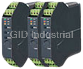
M-Systems M3LR M3-UNIT Series PC Programmable Signal Conditioner; RTD Transmitter (Field- and PC-Configurable)
Part Number
M3LR
Price
Request Quote
Manufacturer
M-SYSTEMS
Lead Time
Request Quote
Category
Signal Conditioning
Specifications
Accuracy
See Table 1
Burnout
Upscale (default), downscale or no burnout selectable
Burnout response
Less than or equal to 10 sec
Configuration
PC configurator
Connection
Euro type connector terminal
DC Power input
Approx. 3 W
Dielectric strength
1500 V AC @ 1 minute (input to output or power to ground); 500 V AC @ 1 minute (output to power)
Housing material
Flame-resistant resin (gray)
Insulation resistance
Greater than or equal to 100 M Omega with 500 V DC
Isolation
Input to output to power
Line voltage effect
±0.1 % over voltage range
Max. 55°C (131°F) for UL approval
Installation
Mounting
DIN rail
One-Step Cal’ calibration
With I/O type and the full-scale range configured via the internal DIP switches, precise 0 % and 100 % ranges are calibrated via the front control buttons with a help of LED.
Operating humidity
0 to 95 %RH (non-condensing)
Operating temperature
-25 to +65°C (-13 to +149°F)
Over-range output
-15 to +115 %
Response time
Less than or equal to 0.9 sec. (0 – 90 %)
Span adjustment
85 to 115 % (front)
Status indicator LED
Tri-color (green/amber/red) LED; Flashing patterns indicate operation status of the transmitter.
Temp. coefficient
±0.015 %/°C (±0.008 %/°F) of max. range at -5 to +55°C (23 to 131°F)
Weight
100 g (3.53 oz)
Zero adjustment
-15 to +15 % (front)
Features
- Accepts an RTD input and provides an isolated, linearized DC signal
- Both input and output type and range are configurable
- CE marking
- Easy ‘One-Step Cal’ calibration using the front three control buttons without needing a PC; PC software is also usable.
- Front control button function can be locked
- Linearization and burnout
- UL approval
Datasheet

Extracted Text
MODEL: M3LR Space-saving Signal Conditioners M3-UNIT Series POWER INPUT DC Power R4: 10 – 32 V DC RTD TRANSMITTER (Operational voltage range 9 - 36 V, ripple 10 %p-p max.) (field- and PC-configurable) Functions & Features • Accepts an RTD input and provides an isolated, linearized [1] CONFIGURATION OPTIONS DC signal A: PC and field configurable • Easy ‘One-Step Cal’ calibration using the front three B: Field configurable control buttons without needing a PC; PC software is also usable. [2] OPTIONS • Both input and output type and range are configurable STANDARDS & APPROVALS • Front control button function can be locked blank: CE marking • Linearization and burnout /UL: UL approval, CE marking • CE marking • UL approval RELATED PRODUCTS • PC configurator software (model: M3CON) 18 (.71) Downloadable at M-System’s web site. A dedicated cable is required to connect the module to the PC. Please refer to the internet software download site or 106 the users manual for the PC configurator for applicable (4.17) cable types. GENERAL SPECIFICATIONS 110.5 (4.35) Construction: Small-sized front terminal structure mm (inch) Connection: Euro type connector terminal Housing material: Flame-resistant resin (gray) MODEL: M3LR–R4/[1][2] Isolation: Input to output to power Overrange output: -15 to +115 % Zero adjustment: -15 to +15 % (front) ORDERING INFORMATION Span adjustment: 85 to 115 % (front) • Code number: M3LR-R4/[1][2] Burnout: Upscale (default), downscale or no burnout Specify a code from below for [1] and [2]. selectable (e.g. M3LR-R4/A) Status indicator LED: Tri-color (green/amber/red) LED; • Orders will be shipped with default factory settings (3-wire Flashing patterns indicate operation status of the Pt 100, 0 – 100°C input/4 – 20 mA output). transmitter. Configuration: PC configurator INPUT – Field-selectable Programmable features include: RTD • I/O type, number of wires and range Pt 100, Pt 200, Pt 300, Pt 400, Pt 500, Pt 1000, • Zero and span adjustments Ni 100, Ni 120, Ni 508.4, Ni-Fe 604, • Burnout action Cu 10 @25°C, Pt 50Ω, JPt 100 • User’s RTD table setting (max. 300 points, input resistance specified within 0 – 30 kΩ) OUTPUT – Field-selectable (Refer to the instruction manual) Current ‘One-Step Cal’ calibration: With I/O type and the full-scale 0 – 20 mA DC range configured via the internal DIP switches, precise 0 % Voltage and 100 % ranges are calibrated via the front control -2.5 – +2.5 V DC buttons with a help of LED. -10 – +10 V DC http://www.m-system.co.jp/ M3LR SPECIFICATIONS ES-2662 Rev.7 Page 1/4 MODEL: M3LR INPUT SPECIFICATIONS CALCULATION EXAMPLES OF OVERALL ACCURACY ■ RTD: See Table 1. ■ CALCULATION EXAMPLES OF OVERALL ACCURACY IN % Number of wires: 2, 3 or 4 wires 1) Pt 100, 0 – 500°C, 4 – 20 mA DC output Excitation: ≤ 1.0 mA Absolute value accuracy (Table 1): 0.15°C Allowable leadwire resistance: 20 Ω per wire 0.15°C / 500°C × 100 = 0.03 % < 0.1% Temperature range: See Table 1. Output span 16 mA (20 – 4) ≥ 2 mA (max. span 20 mA × 0.1) ➠ No adding 0.2 % ➠ Overall accuracy = ±0.1 % of span OUTPUT SPECIFICATIONS 2) Pt 100, 0 – 100°C, 2.0 – 2.5 V DC output ■ DC CURRENT Absolute value accuracy (Table 1): 0.15°C Maximum range: 0 – 20 mA DC 0.15°C / 100°C × 100 = 0.15 % > 0.1 % Minimum span: 1 mA Output span 0.5 V (2.5 – 2.0) ≤ 0.5 (max. span 5 V × 0.1) ➠ Conformance range: 0 – 24 mA DC (Negative overrange Add 0.2 % current below 0 mA is not available.) ➠ Overall accuracy = 0.15 + 0.2 = ±0.35 % of span Offset: Lower range can be any specific value within the output range provided that the minimum span is maintained. STANDARDS & APPROVALS Load resistance: Output drive 12 V maximum CE conformity: ■ DC VOLTAGE EMC Directive (2004/108/EC) Narrow Spans (mV) EMI EN 61000-6-4: 2007 Maximum range: -2.5 – +2.5 V DC EMS EN 61000-6-2: 2005 Minimum span: 250 mV Approval: Conformance range: -3 – +3 V DC UL/C-UL general safety requirements Wide Spans (V) (UL 61010-1, CAN/CSA-C22.2 No.1010-1) Maximum range: -10 – +10 V DC Minimum span: 1 V Conformance range: -11.5 – +11.5 V DC Offset: Lower range can be any specific value within the output range provided that the minimum span is maintained. Load resistance: Output drive 1 mA maximum INSTALLATION Power Consumption •DC power input: Approx. 3 W Operating temperature: -25 to +65°C (-13 to +149°F) Max. 55°C (131°F) for UL approval Operating humidity: 0 to 95 %RH (non-condensing) Mounting: DIN rail Weight: 100 g (3.53 oz) PERFORMANCE Accuracy: See Table 1. Temp. coefficient: ±0.015 %/°C (±0.008 %/°F) of max. range at -5 to +55°C (23 to 131°F) Response time: ≤ 0.9 sec. (0 – 90 %) Burnout response: ≤ 10 sec. Line voltage effect: ±0.1 % over voltage range Insulation resistance: ≥ 100 MΩ with 500 V DC Dielectric strength: 1500 V AC @ 1 minute (input to output or power to ground) 500 V AC @ 1 minute (output to power) http://www.m-system.co.jp/ M3LR SPECIFICATIONS ES-2662 Rev.7 Page 2/4 MODEL: M3LR EXTERNAL VIEW ■ FRONT VIEW ■ SIDE VIEW LED1 (LD1) 10 11 12 LED2 (LD2) Configuration DIP SW 7 8 9 LED3 (LD3) 4 3 2 1 MODE Button OFF UP Button ON DOWN Button SW1 Configurator Jack SW2 8 7 6 5 4 3 2 1 SW3 OFF 1 2 3 ON 4 5 6 4 3 2 1 OFF ON INPUT TYPE, RANGE & ACCURACY Table 1 °C °F RTD MIN. ACCURACY MIN. ACCURACY MAXIMUM RANGE MAXIMUM RANGE SPAN *1 SPAN *1 Pt 100 (JIS ’97, IEC) 20 -200 to +850 ±0.15 36 -328 to +1562 ±0.27 Pt 200 20 -200 to +850 ±0.15 36 -328 to +1562 ±0.27 Pt 300 20 -200 to +850 ±0.15 36 -328 to +1562 ±0.27 Pt 400 20 -200 to +850 ±0.15 36 -328 to +1562 ±0.27 Pt 500 20 -200 to +850 ±0.15 36 -328 to +1562 ±0.27 Pt 1000 20 -200 to +850 ±0.15 36 -328 to +1562 ±0.27 Pt 50 (JIS ’81) 20 -200 to +649 ±0.15 36 -328 to +1200 ±0.27 JPt 100 (JIS ’89) 20 -200 to +510 ±0.15 36 -328 to +950 ±0.27 Ni 100 20 -80 to +260 ±0.15 36 -112 to +500 ±0.27 Ni 120 20 -80 to +260 ±0.15 36 -112 to +500 ±0.27 Ni 508.4 20 -50 to +200 ±0.15 36 -58 to +392 ±0.27 Ni-Fe 604 20 -200 to +200 ±0.15 36 -328 to +392 ±0.27 Cu 10 @25°C 20 -50 to +250 ±0.50 36 -58 to +482 ±0.90 *1. Or ±0.1% of span, whichever is greater. EXTERNAL DIMENSIONS & TERMINAL ASSIGNMENTS unit: mm (inch) 10 11 12 7 8 9 DIN RAIL 35mm wide 1 2 3 4 5 6 18 (.71) 110.5 (4.35) [5 (.20)] • When mounting, no extra space is needed between units. http://www.m-system.co.jp/ M3LR SPECIFICATIONS ES-2662 Rev.7 Page 3/4 106 (4.17) 62 (2.44) MODEL: M3LR SCHEMATIC CIRCUITRY & CONNECTION DIAGRAM 3 9 STATUS CONTROL BUTTONS 2-wire 3-wire 4-wire DIP SW 6 10 Isolation RTD RTD RTD Output Output + A A A 1 7 Computation Driver Low Drift OUTPUT Amplifier – B B 2 8 & Burnout + 11 POWER – A 4 12 B B B 5 CONFIGURATOR JACK Terminal Block Specifications are subject to change without notice. http://www.m-system.co.jp/ M3LR SPECIFICATIONS ES-2662 Rev.7 Page 4/4
Frequently asked questions
How does Industrial Trading differ from its competitors?

Is there a warranty for the M3LR?
Which carrier will Industrial Trading use to ship my parts?
Can I buy parts from Industrial Trading if I am outside the USA?
Which payment methods does Industrial Trading accept?
Why buy from GID?

Quality
We are industry veterans who take pride in our work

Protection
Avoid the dangers of risky trading in the gray market

Access
Our network of suppliers is ready and at your disposal

Savings
Maintain legacy systems to prevent costly downtime

Speed
Time is of the essence, and we are respectful of yours
Related Products
Request a Quote

The quote request has been received
Close

Facing challenges or have inquiries? Feel free to contact us!
Call Us +1-469-283-2440
What they say about us
FANTASTIC RESOURCE
One of our top priorities is maintaining our business with precision, and we are constantly looking for affiliates that can help us achieve our goal. With the aid of GID Industrial, our obsolete product management has never been more efficient. They have been a great resource to our company, and have quickly become a go-to supplier on our list!
Bucher Emhart Glass
EXCELLENT SERVICE
With our strict fundamentals and high expectations, we were surprised when we came across GID Industrial and their competitive pricing. When we approached them with our issue, they were incredibly confident in being able to provide us with a seamless solution at the best price for us. GID Industrial quickly understood our needs and provided us with excellent service, as well as fully tested product to ensure what we received would be the right fit for our company.
Fuji
HARD TO FIND A BETTER PROVIDER
Our company provides services to aid in the manufacture of technological products, such as semiconductors and flat panel displays, and often searching for distributors of obsolete product we require can waste time and money. Finding GID Industrial proved to be a great asset to our company, with cost effective solutions and superior knowledge on all of their materials, it’d be hard to find a better provider of obsolete or hard to find products.
Applied Materials
CONSISTENTLY DELIVERS QUALITY SOLUTIONS
Over the years, the equipment used in our company becomes discontinued, but they’re still of great use to us and our customers. Once these products are no longer available through the manufacturer, finding a reliable, quick supplier is a necessity, and luckily for us, GID Industrial has provided the most trustworthy, quality solutions to our obsolete component needs.
Nidec Vamco
TERRIFIC RESOURCE
This company has been a terrific help to us (I work for Trican Well Service) in sourcing the Micron Ram Memory we needed for our Siemens computers. Great service! And great pricing! I know when the product is shipping and when it will arrive, all the way through the ordering process.
Trican Well Service
GO TO SOURCE
When I can't find an obsolete part, I first call GID and they'll come up with my parts every time. Great customer service and follow up as well. Scott emails me from time to time to touch base and see if we're having trouble finding something.....which is often with our 25 yr old equipment.
ConAgra Foods