

 Manufacturers
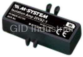
M-SYSTEMS M2XPA2

Description
M-Systems M2XPA2 Mini-M Series Super-mini Signal Conditioner; Frequency Transmitter (PC Programmable)
Part Number
M2XPA2
Price
Request Quote
Manufacturer
M-SYSTEMS
Lead Time
Request Quote
Category
Signal Conditioning
Specifications
Accuracy
Input accuracy + output accuracy; Inversely proportional to the span
Connection
M3 screw terminals (torque 0.8 N-m)
Construction
Plug-in
Dielectric strength
2000 V AC @1 minute (input to output to power to ground)
Housing Material
Flame-resistant resin (black)
Input accuracy
±0.03 % of the selected freq. range
Isolation
Input to output to power
Line voltage effect
±0.1 % over voltage range
Mechanical Contact Input amplitude
Min. 4 V, max. 12 V
Mechanical Contact Maximum frequency
0 – 10 Hz
Mechanical Contact Sensing voltage / current
Approx. 12 V, 8 V or 4 V DC @1 mA
Open Collector Input amplitude
Min. 4 V, max. 12 V
Open Collector Maximum frequency
0 – 100 kHz
Open Collector Sensing voltage/ current
Approx. 12 V, 8 V or 4 V DC @1 mA
Output accuracy
±0.03 % of the selected output range
Over-range output
Approx. -15 to +115 % at 1 – 5 V
Pulse width time requirement
Min. 5 µsec., max. 10 sec
Response time
Ts + Td (0 – 90 %)
Span adjustment
95 to 105 % (front)
Temp. coefficient
±0.015 %/°C (±0.008 %/°F) of I/O range at -5 to +55°C [23 to 131°F]
Voltage Pulse Detecting levels
-2 – +4V
Voltage Pulse Input amplitude
Min. 0.1 Vp-p, max. 100 Vp-p
Voltage Pulse Input impedance
10 kO min.
Voltage Pulse Maximum frequency
0 – 100 kHz
Voltage Pulse Waveform
Square or sine
Zero adjustment
-5 to +5 % (front)
Features
- 2000V AC isolation
- Base socket included with modules
- CE marking and UL/C-UL Class 1 Div 2 approval (selected models)
- Fixed range or PC programmable models selectable
- M2 use a compact-size, plug-in socket base for quick installation or replacement of modules without disturbing wiring.
- Selectable 100-240V AC/24V DC power input
- Standard DIN rail or surface mounting
Datasheet

Extracted Text
MODEL: M2XPA2 Configurator software is used to change the frequency Super-mini Signal Conditioners Mini-M Series range. The input type can be switched to other than the one of the selected suffix code by selecting the input type DISCONTINUED MODEL selectors inside the unit before software adjustment. Replaced with Model M2XPA3 [2] EXCITATION FREQUENCY TRANSMITTER 0: User-calibrated (Factory default: 12 V DC / 5 mA) (PC programmable) If the unit is to be factory-calibrated to a specific Functions & Features voltage value, please select from the following: • Converts the output from a pulse-type transducer into a 2: 4 V DC / 5 mA standard process signal 3: 8 V DC / 5 mA • PC programmable 4: 12 V DC / 5 mA • Sensor excitation Configurator software is used to change the excitation • Direct RS-422 input value. • CE marking • UL approval [3] OUTPUT 0: User-calibrated (Factory default: 4 – 20 mA) Typical Applications If the unit is to be factory-calibrated to a specific • Positive displacement flowmeters, turbine flowmeters and output type, please select from the following: vortex flowmeters Current • Measuring rotation speed of a machine generating dry Z1: Range 0 – 20 mA DC contact signals Voltage V1: Range -2.5 – +2.5 V DC V2: Range -10 – +10 V DC MODEL: M2XPA2-[1][2][3]-[4][5] (Configurator software is used to adjust the output range and to change the output over the described range of the selected suffix code.) ORDERING INFORMATION • Code number: M2XPA2-[1][2][3]-[4][5] Specify a code from below for each [1] through [5]. [4] POWER INPUT (e.g. M2XPA2-A14Z1-M2/CE/Q) AC Power • Specify the specification for option code /Q M2: 100 – 240 V AC (Operational voltage range 85 – 264 V, (e.g. /C01/S01) 47 – 66 Hz) • Non-specified orders will be shipped at default factory (90 – 264 V for UL) settings (M2XPA2-000: Open collector input/12 V DC Power excitation/4– 20 mA output). However, a power suffix code R: 24 V DC must be specified. (Operational voltage range 24 V ±10 %, ripple 10 %p-p max.) If you specify a full code number without specific calibration P: 110 V DC ranges, the input frequency is factory set to the maximum (Operational voltage range 85 – 150 V, ripple 10 %p-p max.) range available for the selected input code and the output is (110 V ±10 % for UL) set to the default range. Use Ordering Information Sheet (No. ESU-5060). [5] OPTIONS (multiple selections) STANDARDS & APPROVALS (must be specified) [1] INPUT /N: Without CE or UL 0: User-calibrated (Factory default: open collector, 0 – 100 kHz) /CE: CE marking If the unit is to be factory-calibrated to a specific /UL: UL approval (CE marking) input type, please select from the following: OTHER OPTIONS A1: Open collector blank: none A2: Mechanical contact /Q: Option other than the above (specify the specification) B: Voltage pulse (UL not available) G: Two-wire current pulse J: RS-422 line driver pulse http://www.m-system.co.jp/ M2XPA2 SPECIFICATIONS ES-5060 Rev.11 Page 1/5 MODEL: M2XPA2 Waveform: Square or sine SPECIFICATIONS OF OPTION: Q (multiple selections) Input impedance: 10 kΩ min. COATING (For the detail, refer to M-System's web site.) Input amplitude: Min. 0.1 Vp-p, max. 100 Vp-p /C01: Silicone coating Maximum voltage between input terminals: See table 1. /C02: Polyurethane coating Detecting levels: -2 – +4 V /C03: Rubber coating If not specified, the input range is 0 – 100 kHz. TERMINAL SCREW MATERIAL • Two-wire Current Pulse /S01: Stainless steel Maximum frequency: 0 – 100 kHz Input resistance: Receiving resistor 100 Ω RELATED PRODUCTS Input range: 0 – 25 mA • JX configurator connection kit (model: JXCON) Input amplitude: Min. 4 mA, max. 20 mA Detecting levels: -2 – +4 V If not specified, the input range is 0 – 100 kHz. GENERAL SPECIFICATIONS • RS-422 LINE DRIVER PULSE Construction: Plug-in Maximum frequency: 0 – 100 kHz Connection: M3 screw terminals (torque 0.8 N·m) Receiver: Conforms to RS-422 Housing material: Flame-resistant resin (black) If not specified, the input range is 0 – 100 kHz. Isolation: Input to output to power [Table 1.(Voltage Pulse)] Overrange output: Approx. -15 to +115 % at 1 – 5 V Zero adjustment: -5 to +5 % (front) AMPLITUDE MAXIMUM VOLTAGE 1 Span adjustment: 95 to 105 % (front) 50 – 100V p-p 100V * 25 – 50V p-p 50V Configuration: Via PC Configurator Software (model: JXCON) 10 – 25V p-p 25V on the Windows PC connected to the front jack. 5 – 10V p-p 10V Programmable features include: I/O type and range, Zero 1 – 5V p-p 5V and span adjustments, Low-end cutout, etc. 0.5 – 1V p-p 1V 2 0.1 – 0.5V p-p 0.5V * DIP switch settings: *1, Max. 70V for CE conformance or UL approval. • Input Type *2, Max. input frequency limited to 50 kHz. • Pulse Sensing (Capacitor Coupled, DC Coupled) • Noise Filter Large (time constant 50 ms), Small (time constant 10 ms), OUTPUT SPECIFICATIONS Without • DC Current:Operational range: 0 – 24 mA DC Output range: 0 – 20 mA DC Minimum span: 1 mA INPUT SPECIFICATIONS Offset: Lower range can be any specific value within the Measurable frequencies: Minimum span 10 % of the output range provided that the minimum span is frequency range selected among: maintained. 0 – 10 Hz, 0 – 100 Hz, 0 – 1 kHz, 0 – 10 kHz, 0 – 100 kHz Load resistance: Output drive 12 V max. Pulse width time requirement: Min. 5 μsec., max. 10 sec. (e.g. 4 – 20 mA: 600 Ω [12 V / 20 mA]) • Open Collector If not specified, the output range is 4 – 20 mA DC. Maximum frequency: 0 – 100 kHz • DC VOLTAGE Input amplitude: Min. 4 V, max. 12 V Code V1 (narrow spans) Sensing voltage / current: Conformance range: -3 – +3 V DC Approx. 12 V, 8 V or 4 V DC @1 mA Output range: -2.5 – +2.5 V DC Detecting levels: ≤ 200 Ω for ON; ≥ 200 kΩ for OFF Minimum span: 250 mV If not specified, the input range is 0 – 100 kHz. Code V2 (wide spans) • Mechanical Contact Conformance range: -11.5 – +11.5 V DC Maximum frequency: 0 – 10 Hz Output range: -10 – +10 V DC Input amplitude: Min. 4 V, max. 12 V Minimum span: 1 V Sensing voltage / current: Offset: Lower range can be any specific value within the Approx. 12 V, 8 V or 4 V DC @1 mA output range provided that the minimum span is Detecting levels: ≤ 200 Ω for ON; ≥ 200 kΩ for OFF maintained. If not specified, the input range is 0 – 10 Hz. Load resistance: Output drive 1 mA max. • Voltage Pulse (e.g. 1 – 5 V: 5000 Ω [5 V / 1 mA]) Maximum frequency: 0 – 100 kHz http://www.m-system.co.jp/ M2XPA2 SPECIFICATIONS ES-5060 Rev.11 Page 2/5 MODEL: M2XPA2 If not specified, the output range is shown below. CALCULATION EXAMPLES OF OVERALL ACCURACY V1: 0 – 1 V DC [Example] Open collector input, 0 – 50 kHz; 1 – 5 V output. V2: 1 – 5 V DC Selected freq. range (100 kHz) / Input span (50 kHz)× Accuracy (0.03 %)= 0.06 % (Input accuracy) Selected output range (20 V) / Output span (4 V) × INSTALLATION Accuracy (0.03 %)= 0.15 % (Output accuracy) Power Consumption Overall accuracy = 0.06 + 0.15 = ±0.21 % •AC Power input: Approx. 4 VA at 100 V Approx. 5 VA at 200 V STANDARDS & APPROVALS Approx. 6 VA at 264 V CE conformity: •DC Power input: Approx. 3 W EMC Directive (2004/108/EC) Operating temperature: -5 to +55°C (23 to 131°F) EN 61000-6-4 (EMI) Operating humidity: 30 to 90 %RH (non-condensing) EN 61000-6-2 (EMS) Mounting: Surface or DIN rail Low Voltage Directive (2006/95/EC) Weight: 150 g (0.33 lbs) EN 61010-1 Installation Category II Pollution Degree 2 PERFORMANCE Max. operating voltage 300 V Accuracy: Input accuracy + output accuracy Input or output to power: Reinforced insulation Inversely proportional to the span. Input to output: Basic insulation Input accuracy: ±0.03 % of the selected freq. range Approval: Output accuracy: ±0.03 % of the selected output range UL/C-UL nonincendive Class I, Division 2, See CALCULATION EXAMPLES OF OVERALL ACCURACY. Groups A, B, C, and D hazardous locations Temp. coefficient: ±0.015 %/°C (±0.008 %/°F) of I/O range (ANSI/ISA-12.12.01, CAN/CSA-C22.2 No.213) at -5 to +55°C [23 to 131°F] UL/C-UL general safety requirements Response time: Ts + Td (0 – 90 %) (UL 61010B-1, CAN/CSA-C22.2 No.1010-1) Ts : Measuring Time = Sampling time x 4 Td : Delay = 300 msec. [Example] Sampling time 50 msec. (standard setting) Delay time 300 msec. When the input cycle is shorter than the sampling time, the response time is calculated as: 50 msec. x 4 + 300 msec. = 500 msec. When the input cycle is longer than the sampling time, the response time becomes longer accordingly. Line voltage effect: ±0.1 % over voltage range Insulation resistance: ≥ 100 MΩ with 500 V DC Dielectric strength: 2000 V AC @1 minute (input to output to power to ground) ■RESPONSE TIME Measuring Time Input Output Ts Td Ts : Measuring Time = Sampling time x 4 Td : Delay = 300 msec. http://www.m-system.co.jp/ M2XPA2 SPECIFICATIONS ES-5060 Rev.11 Page 3/5 MODEL: M2XPA2 EXTERNAL VIEW � FRONT VIEW (with cover open) � LEFT SIDE VIEW (with cover removed) Configurator Jack Selector SW Status Indictor LED 4 3 2 1 OFF ON Zero/Span Selector SW4 Top: SPAN Middle: OFF Bottom: ZERO UP/DOWN Switches L H L H L H The front cover cannot be opened to 180 deg. SW1 SW2 SW3 when flush with neighboring units. Refer to the instruction manual for detailed procedures. DIMENSIONS unit: mm (inch) 6 (.23) DIN RAIL 4 1 35mm wide 8 5 2–4.2x5 (.17x.20) MTG HOLE 6 (.24) deep 12 9 8–M3 SCREW 14 13 21.5 (.85) 7.3 (.29) 86.7 (3.41) 15 (.59) 116.7 (4.59) [4 (.16)] 23 (.91) • When mounting, no extra space is needed between units. http://www.m-system.co.jp/ M2XPA2 SPECIFICATIONS ES-5060 Rev.11 Page 4/5 70.5 (2.78) 59 (2.32) 4 (.16) 72 (2.83) MODEL: M2XPA2 SCHEMATIC CIRCUITRY & CONNECTION DIAGRAM STATUS INPUT TYPE MON. ZERO/SPAN SELECTOR SELECTOR Isolation Digital Output + 1 9 Waveform Computation Driver OUTPUT Shaper – 4 12 1 INPUT * UP/DOWN SWITCHES 5 13 U(+) Excitation POWER Supply 8 14 V(–) CONFIGURATOR JACK Base Socket *1. Input Connection Examples � Dry Contact � Voltage Pulse � 2-Wire Current Pulse + + 1 1 4 – – + 4 4 5 100Ω – – INPUT PWR PWR – + + 5 5 8 � Mechanical Contact � RS-422 Line Driver Pulse + + 1 1 INPUT – 4 – 4 – + PWR 5 + 5 PWR 8 – EXPLANATIONS OF TERMS Low-end cutout: The function where the output signal is forced to 0% below the setpoint input. [Example] Input zero frequency 0 Hz Input span frequency 1 kHz Low-end cutout 10 % OUTPUT INPUT 0% 10% 100% 0 Hz 100 Hz 1 kHz Specifications are subject to change without notice. http://www.m-system.co.jp/ M2XPA2 SPECIFICATIONS ES-5060 Rev.11 Page 5/5
Frequently asked questions
How does Industrial Trading differ from its competitors?

Is there a warranty for the M2XPA2?
Which carrier will Industrial Trading use to ship my parts?
Can I buy parts from Industrial Trading if I am outside the USA?
Which payment methods does Industrial Trading accept?
Why buy from GID?

Quality
We are industry veterans who take pride in our work

Protection
Avoid the dangers of risky trading in the gray market

Access
Our network of suppliers is ready and at your disposal

Savings
Maintain legacy systems to prevent costly downtime

Speed
Time is of the essence, and we are respectful of yours
Related Products
Request a Quote

The quote request has been received
Close

Facing challenges or have inquiries? Feel free to contact us!
Call Us +1-469-283-2440
What they say about us
FANTASTIC RESOURCE
One of our top priorities is maintaining our business with precision, and we are constantly looking for affiliates that can help us achieve our goal. With the aid of GID Industrial, our obsolete product management has never been more efficient. They have been a great resource to our company, and have quickly become a go-to supplier on our list!
Bucher Emhart Glass
EXCELLENT SERVICE
With our strict fundamentals and high expectations, we were surprised when we came across GID Industrial and their competitive pricing. When we approached them with our issue, they were incredibly confident in being able to provide us with a seamless solution at the best price for us. GID Industrial quickly understood our needs and provided us with excellent service, as well as fully tested product to ensure what we received would be the right fit for our company.
Fuji
HARD TO FIND A BETTER PROVIDER
Our company provides services to aid in the manufacture of technological products, such as semiconductors and flat panel displays, and often searching for distributors of obsolete product we require can waste time and money. Finding GID Industrial proved to be a great asset to our company, with cost effective solutions and superior knowledge on all of their materials, it’d be hard to find a better provider of obsolete or hard to find products.
Applied Materials
CONSISTENTLY DELIVERS QUALITY SOLUTIONS
Over the years, the equipment used in our company becomes discontinued, but they’re still of great use to us and our customers. Once these products are no longer available through the manufacturer, finding a reliable, quick supplier is a necessity, and luckily for us, GID Industrial has provided the most trustworthy, quality solutions to our obsolete component needs.
Nidec Vamco
TERRIFIC RESOURCE
This company has been a terrific help to us (I work for Trican Well Service) in sourcing the Micron Ram Memory we needed for our Siemens computers. Great service! And great pricing! I know when the product is shipping and when it will arrive, all the way through the ordering process.
Trican Well Service
GO TO SOURCE
When I can't find an obsolete part, I first call GID and they'll come up with my parts every time. Great customer service and follow up as well. Scott emails me from time to time to touch base and see if we're having trouble finding something.....which is often with our 25 yr old equipment.
ConAgra Foods