

 Manufacturers
ARCOM SBC-MediaGX-233-M0-F0
Description
233MHz CPU, No DRAM, No Flash
Part Number
SBC-MediaGX-233-M0-F0
Price
Request Quote
Manufacturer
ARCOM
Lead Time
Request Quote
Category
Single Board Computers
Specifications
Form Factor
PC/104
Audio Interface
16-bit SoundBlaster compatible
Battery
3.0V Lithium 180mAH (CR2032 Coin Cell); Maximum discharge current 2uA
CPU
National/Cyrix MediaGX MMX-enhanced processor
Dimensions
EBX Compatible Format; 5.75" x 8.00"
Expansion
PC/104-Plus Interface
Floppy Disk Drive
2 drives supported
Humidity
10% to 90% RH (Non-condensing)
IDE Interface
2 drives supported
Keyboard/Mouse
PS/2 Style
MTBF
Based on MIL-SPEC-217F using generic failure rates
Operating Temperature
-20º to +60ºC
Parallel Ports
SPP/EPP/ECP
Power Requirements
+5V +/- 5% 1.9A (typical), 3A (max)
Processor
Cyrix MMX
Real Time Clock
Accuracy +/- 1min/month
Resolution
640 x 480 8/16/24 bpp; 800 x 600 8/16/24 bpp; 1024 x 768 8/16 bpp; 1280 x 1024 8 bpp
Serial Ports
COM1,COM2,COM3 RS232 COM4 RS232/422/485
Software
Datalight ROM-DOS operating system; Datalight FlashFX flash filing system
Storage Temperature
-40º to +85ºC
System Memory
16MB, 32MB, 64MB, 128MB 3.3V unbuffered SDRAM DIMM Module; 4M, 8M, 16M Intel Strata Flash; 256K Flash BIOS EPROM
Touchscreen Interface
4-wire analogue resistive
USB
Dual channel support
VGA Video
Intel/Chips and Technologies 69000 HiQVideo; 2M SDRAM Video Memory
Weight
400g
Features
- 16K L1 write-back cache
- 2MB integrated SDRAM
- Audio
- Award Software PCI Plug and Play BIOS in Flash EPROM
- EIDE up to Two devices support PIO Mode 4 or Ultra DMA/33 Hard Disk and ATAPI CD-ROM
- Four 16C550 compatible high speed UART's
- Intel/Chips & Technologies 69000 HiQVideo BIOS
- National/Cyrix MediaGX 233MHz MMX-enhanced processor
- PC/104-Plus expansion bus; 8/16 bit ISA compatible interface; 32-bit PCI compatible interface
- Two Universal Serial Bus (USB) interfaces
- Up to 128MB Unbuffered 3.3V SDRAM
- Up to 16MB Intel Strata Flash
- XVGA for CRT and Flat panel displays
Datasheet

Extracted Text
J629 SBC-MediaGX 2192-10048-000-000
Arcom SBC-MediaGX
EBX Compatible
Embedded Processor Card
Technical Manual
Product Information
Full information about other Arcom products is available via the F Fa ax x- -o on n- -D De em ma an nd d S Sy ys st te em m, (Telephone
W We eb bS Si it te e w ww ww w. .a ar rc co om mc co on nt tr ro ol ls s. .c co om m
Numbers are listed below), or by contacting our at:
U Us se ef fu ul l C Co on nt ta ac ct t I In nf fo or rm ma at ti io on n
C Cu us st to om me er r S Su up pp po or rt t S Sa al le es s o or r f fo or r t th he e U US S: : E E- -m ma ai il l
Tel: +44 (0)1223 412 428 Tel: +44 (0)1223 411 200 icpsales@arcomcontrols.com
Fax: +44 (0)1223 403 409 Fax: +44 (0)1223 410 457
E-mail: support@arcom.co.uk E-mail sales@arcom.co.uk
U Un ni it te ed d K Ki in ng gd do om m U Un ni it te ed d S St ta at te es s B Be el lg gi iu um m G Ge er rm ma an ny y I It ta al ly y
Arcom Control Systems Ltd Arcom Control Systems Inc Groen Nummer: Kostenlose Infoline: Numero Verde:
Clifton Road 13510 South Oak Street Tel: 0800 7 3192 Tel: 0130 824 511 Tel: 0800 790841
Cambridge CB1 7EA, UK Kansas City MO 64145 USA Fax: 0800 7 3191 Fax: 0130 824 512 Fax: 0800 780841
Tel: 01223 411 200 Tel: 816 941 7025 FoD: 0130 860 449 FoD: 0800 873600
F Fr ra an nc ce e
Fax: 01223 410 457 Fax: 816 941 0343
Numero Verto
FoD: 01223 240 600 FoD: 800 747 1097 N Ne et th he er rl la an nd ds s
Tel: 0800 90 84 06
Gratis 0800 Nummer:
Fax: 0800 90 84 12
Tel: 0800 0221136
FoD: 0800 90 23 80
Fax: 0800 022114
Whilst Arcom�s sales team is always available to assist you in making your decision, the final choice of
boards or systems is solely and wholly the responsibility of the buyer. Arcom�s entire liability in respect
of the boards or systems is as set out in Arcom�s standard terms and conditions of sale.
If you intend to write your own low level software, you can start with the source code on the disk which
is supplied. This is example code only to illustrate use on Arcom�s products. It has not been
Arcom Control Systems
commercially tested. No warranty is made in respect of this code and Arcom shall incur no liability
Ltd operate a company-
whatsoever or howsoever arising from any use made of the code.
wide quality management
system which has been
certified by the British
' 1999 Arcom Control Systems Ltd
Standards Institution
Arcom Control Systems is a subsidiary of Fairey Group Plc.
(BSI) as compliant with
All trademarks recognised.
ISO9001:1994
Page 1
CONTROL SYSTEMS
2192-10048-000-000 J629 SBC-MediaGX
Disclaimer
The information in this manual has been carefully checked and is believed to be accurate.
Arcom Control Systems assumes no responsibility for any infringements of patents or other
rights of third parties which may result from its use.
Arcom Control Systems assumes no responsibility for any inaccuracies that may be contained
in this document. Arcom Control Systems makes no commitment to update or keep current
the information contained in this manual.
Arcom Control Systems reserves the right to make improvements to this document and /or
product at any time and without notice.
Anti-Static Handling
This board contains CMOS devices that could be damaged in the event of static electricity
discharged through them. At all times, please observe anti-static precautions when handling
the board. This includes storing the board in appropriate anti-static packaging and wearing a
wrist strap when handling the board.
Battery
The board contains a Lithium non-rechargeable battery. Do not short circuit the battery or place
on a metal surface where the battery terminals could be shorted. During shipment the battery
is isolated from the boards circuitry and should be connected before using the board, please
refer to the link section of this manual for details.
When disposing of the board or battery, take appropriate care. Do not incinerate, crush or
otherwise damage the battery.
Packaging
Please ensure that should a board need to be returned to Arcom Control Systems, it is
adequately packed, preferably in the original packing material.
Electromagnetic Compatibility (EMC)
The SBC-MediaGX is classified as a component with regard to the European Community EMC
regulations and it is the users responsibility to ensure that systems using the board are
compliant with the appropriate EMC standards.
Acknowledgments
ROM-DOS, FlashFX, are trademarks of Datalight Inc.
MS-DOS, Windows NT, Windows CE, Windows 95, Windows 98 are trademarks of the
Microsoft Corporation.
Cyrix, MediaGX are trademarks of National Semiconductors ltd
All other trademarks acknowledged
Technical Support
Arcom Control systems has a team of technical support engineers who will be able to provide
assistance if you have any problems with this product. Please contact the support team at
support@arcom.co.uk
Page 2
CONTROL SYSTEMS
J629 SBC-MediaGX 2192-10048-000-000
Contents
Introduction . . . . . . . . . . . . . . . . . . . . . . . . . . . . . . . . . . . . . . . . . . . . . . . . . . . . . . . . . . . . . . .5
Features . . . . . . . . . . . . . . . . . . . . . . . . . . . . . . . . . . . . . . . . . . . . . . . . . . . . . . . . . . . . .6
Getting Started . . . . . . . . . . . . . . . . . . . . . . . . . . . . . . . . . . . . . . . . . . . . . . . . . . . . . . . . . . . . .8
Using the SBC-MediaGX . . . . . . . . . . . . . . . . . . . . . . . . . . . . . . . . . . . . . . . . . . . . . . . . . . . . .8
CPU Configuration . . . . . . . . . . . . . . . . . . . . . . . . . . . . . . . . . . . . . . . . . . . . . . . . . . . . . .8
Installing Memory . . . . . . . . . . . . . . . . . . . . . . . . . . . . . . . . . . . . . . . . . . . . . . . . . . . . . .8
Connecting a Floppy disk drive . . . . . . . . . . . . . . . . . . . . . . . . . . . . . . . . . . . . . . . . . . . .9
Connecting a Hard disk drive . . . . . . . . . . . . . . . . . . . . . . . . . . . . . . . . . . . . . . . . . . . . . .9
Connecting a CD-ROM (IDE Type) . . . . . . . . . . . . . . . . . . . . . . . . . . . . . . . . . . . . . . . . . .9
Connecting a Mouse . . . . . . . . . . . . . . . . . . . . . . . . . . . . . . . . . . . . . . . . . . . . . . . . . . . .9
Using the Serial interfaces (RS232) . . . . . . . . . . . . . . . . . . . . . . . . . . . . . . . . . . . . . . . . .9
Connecting a Printer . . . . . . . . . . . . . . . . . . . . . . . . . . . . . . . . . . . . . . . . . . . . . . . . . . . .10
Using the Audio features . . . . . . . . . . . . . . . . . . . . . . . . . . . . . . . . . . . . . . . . . . . . . . . . .11
Using the Flat Panel Interface . . . . . . . . . . . . . . . . . . . . . . . . . . . . . . . . . . . . . . . . . . . . .12
Using the PC/104-Plus expansion Bus . . . . . . . . . . . . . . . . . . . . . . . . . . . . . . . . . . . . . . .12
Using the USB Ports . . . . . . . . . . . . . . . . . . . . . . . . . . . . . . . . . . . . . . . . . . . . . . . . . . . .12
Using the Ethernet Interface . . . . . . . . . . . . . . . . . . . . . . . . . . . . . . . . . . . . . . . . . . . . . .13
Links & Connectors . . . . . . . . . . . . . . . . . . . . . . . . . . . . . . . . . . . . . . . . . . . . . . . . . . . . . . . . .14
Links . . . . . . . . . . . . . . . . . . . . . . . . . . . . . . . . . . . . . . . . . . . . . . . . . . . . . . . . . . . . . . . .14
Connectors . . . . . . . . . . . . . . . . . . . . . . . . . . . . . . . . . . . . . . . . . . . . . . . . . . . . . . . . . . .17
AWARD BIOS Setup . . . . . . . . . . . . . . . . . . . . . . . . . . . . . . . . . . . . . . . . . . . . . . . . . . . . . . . . .18
Entering Setup . . . . . . . . . . . . . . . . . . . . . . . . . . . . . . . . . . . . . . . . . . . . . . . . . . . . . . . . .18
Getting Help . . . . . . . . . . . . . . . . . . . . . . . . . . . . . . . . . . . . . . . . . . . . . . . . . . . . . . . . . .19
The Main Menu . . . . . . . . . . . . . . . . . . . . . . . . . . . . . . . . . . . . . . . . . . . . . . . . . . . . . . . .20
Standard CMOS Setup . . . . . . . . . . . . . . . . . . . . . . . . . . . . . . . . . . . . . . . . . . . . . . . . . .22
BIOS Features Setup . . . . . . . . . . . . . . . . . . . . . . . . . . . . . . . . . . . . . . . . . . . . . . . . . . . .23
Chipset Features Setup . . . . . . . . . . . . . . . . . . . . . . . . . . . . . . . . . . . . . . . . . . . . . . . . . .28
Power Management . . . . . . . . . . . . . . . . . . . . . . . . . . . . . . . . . . . . . . . . . . . . . . . . . . . . .29
PNP / PCI Configuration Setup . . . . . . . . . . . . . . . . . . . . . . . . . . . . . . . . . . . . . . . . . . . .31
Integrated Peripherals . . . . . . . . . . . . . . . . . . . . . . . . . . . . . . . . . . . . . . . . . . . . . . . . . . .32
Load BIOS Setup . . . . . . . . . . . . . . . . . . . . . . . . . . . . . . . . . . . . . . . . . . . . . . . . . . . . . . .33
Load Setup Default . . . . . . . . . . . . . . . . . . . . . . . . . . . . . . . . . . . . . . . . . . . . . . . . . . . . .33
Supervisor / User Password Setting . . . . . . . . . . . . . . . . . . . . . . . . . . . . . . . . . . . . . . . . .33
IDE HDD Auto Detection . . . . . . . . . . . . . . . . . . . . . . . . . . . . . . . . . . . . . . . . . . . . . . . . .33
Software Support . . . . . . . . . . . . . . . . . . . . . . . . . . . . . . . . . . . . . . . . . . . . . . . . . . . . . . . . . . .34
Datalight ROM-DOS 6.22 . . . . . . . . . . . . . . . . . . . . . . . . . . . . . . . . . . . . . . . . . . . . . . . . .34
Datalight FlashFX Flash Filing System . . . . . . . . . . . . . . . . . . . . . . . . . . . . . . . . . . . . . . .34
AWDflash Utility . . . . . . . . . . . . . . . . . . . . . . . . . . . . . . . . . . . . . . . . . . . . . . . . . . . . . . . .34
Bootdisk . . . . . . . . . . . . . . . . . . . . . . . . . . . . . . . . . . . . . . . . . . . . . . . . . . . . . . . . . . . . .35
Page 3
CONTROL SYSTEMS
2192-10048-000-000 J629 SBC-MediaGX
Operating Systems Drivers . . . . . . . . . . . . . . . . . . . . . . . . . . . . . . . . . . . . . . . . . . . . . . .35
Windows 95 Driver Support . . . . . . . . . . . . . . . . . . . . . . . . . . . . . . . . . . . . . . . . . . . . . . .35
Windows 98 Driver Support . . . . . . . . . . . . . . . . . . . . . . . . . . . . . . . . . . . . . . . . . . . . . . .36
Windows NT4.0 Driver Support . . . . . . . . . . . . . . . . . . . . . . . . . . . . . . . . . . . . . . . . . . . .37
Other Software Support . . . . . . . . . . . . . . . . . . . . . . . . . . . . . . . . . . . . . . . . . . . . . . . . . .38
Hardware Support Information . . . . . . . . . . . . . . . . . . . . . . . . . . . . . . . . . . . . . . . . . . . . .39
Detailed Hardware Description . . . . . . . . . . . . . . . . . . . . . . . . . . . . . . . . . . . . . . . . . . . . . . . . .40
Processor . . . . . . . . . . . . . . . . . . . . . . . . . . . . . . . . . . . . . . . . . . . . . . . . . . . . . . . . . . . .40
Memory . . . . . . . . . . . . . . . . . . . . . . . . . . . . . . . . . . . . . . . . . . . . . . . . . . . . . . . . . . . . . .40
I/O Map . . . . . . . . . . . . . . . . . . . . . . . . . . . . . . . . . . . . . . . . . . . . . . . . . . . . . . . . . . . . . .43
Graphics Controller . . . . . . . . . . . . . . . . . . . . . . . . . . . . . . . . . . . . . . . . . . . . . . . . . . . . .44
Interrupt Assignments . . . . . . . . . . . . . . . . . . . . . . . . . . . . . . . . . . . . . . . . . . . . . . . . . . .46
DMA Controller . . . . . . . . . . . . . . . . . . . . . . . . . . . . . . . . . . . . . . . . . . . . . . . . . . . . . . . .47
IDE Interface . . . . . . . . . . . . . . . . . . . . . . . . . . . . . . . . . . . . . . . . . . . . . . . . . . . . . . . . . .47
Floppy Disk Controller . . . . . . . . . . . . . . . . . . . . . . . . . . . . . . . . . . . . . . . . . . . . . . . . . . .48
Real Time Clock . . . . . . . . . . . . . . . . . . . . . . . . . . . . . . . . . . . . . . . . . . . . . . . . . . . . . . .48
Keyboard/Mouse Controller . . . . . . . . . . . . . . . . . . . . . . . . . . . . . . . . . . . . . . . . . . . . . . .48
Ethernet Controller . . . . . . . . . . . . . . . . . . . . . . . . . . . . . . . . . . . . . . . . . . . . . . . . . . . . . .49
16-Bit SoundBlaster . . . . . . . . . . . . . . . . . . . . . . . . . . . . . . . . . . . . . . . . . . . . . . . . . . . . .49
Watchdog Timer . . . . . . . . . . . . . . . . . . . . . . . . . . . . . . . . . . . . . . . . . . . . . . . . . . . . . . .50
User Link . . . . . . . . . . . . . . . . . . . . . . . . . . . . . . . . . . . . . . . . . . . . . . . . . . . . . . . . . . . . .50
USB Interface . . . . . . . . . . . . . . . . . . . . . . . . . . . . . . . . . . . . . . . . . . . . . . . . . . . . . . . . .50
Touchscreen Controller . . . . . . . . . . . . . . . . . . . . . . . . . . . . . . . . . . . . . . . . . . . . . . . . . .51
General Purpose I/O . . . . . . . . . . . . . . . . . . . . . . . . . . . . . . . . . . . . . . . . . . . . . . . . . . . .51
CPU Temperature Sensor . . . . . . . . . . . . . . . . . . . . . . . . . . . . . . . . . . . . . . . . . . . . . . . .52
PC/104-Plus Interface . . . . . . . . . . . . . . . . . . . . . . . . . . . . . . . . . . . . . . . . . . . . . . . . . . .53
Serial Ports . . . . . . . . . . . . . . . . . . . . . . . . . . . . . . . . . . . . . . . . . . . . . . . . . . . . . . . . . . .53
Parallel Port . . . . . . . . . . . . . . . . . . . . . . . . . . . . . . . . . . . . . . . . . . . . . . . . . . . . . . . . . . .54
Power Supply . . . . . . . . . . . . . . . . . . . . . . . . . . . . . . . . . . . . . . . . . . . . . . . . . . . . . . . . .54
PC Speaker . . . . . . . . . . . . . . . . . . . . . . . . . . . . . . . . . . . . . . . . . . . . . . . . . . . . . . . . . . .56
Suspend/Resume Switch . . . . . . . . . . . . . . . . . . . . . . . . . . . . . . . . . . . . . . . . . . . . . . . . .56
RESET Switch . . . . . . . . . . . . . . . . . . . . . . . . . . . . . . . . . . . . . . . . . . . . . . . . . . . . . . . . .56
CPU Fan Control . . . . . . . . . . . . . . . . . . . . . . . . . . . . . . . . . . . . . . . . . . . . . . . . . . . . . . .56
Appendix A - Connector details . . . . . . . . . . . . . . . . . . . . . . . . . . . . . . . . . . . . . . . . . . . . . . . . .57
Appendix B - Specifications . . . . . . . . . . . . . . . . . . . . . . . . . . . . . . . . . . . . . . . . . . . . . . . . . . .67
Appendix C - SBC-MediaGX Mechanical Diagram . . . . . . . . . . . . . . . . . . . . . . . . . . . . . . . . . .68
Appendix D - SBC-MediaGX FPIF . . . . . . . . . . . . . . . . . . . . . . . . . . . . . . . . . . . . . . . . . . . . . .69
Appendix E - Reference Information . . . . . . . . . . . . . . . . . . . . . . . . . . . . . . . . . . . . . . . . . . . . .73
Appendix F - Troubleshooting . . . . . . . . . . . . . . . . . . . . . . . . . . . . . . . . . . . . . . . . . . . . . . . . . .74
Page 4
CONTROL SYSTEMS
J629 SBC-MediaGX 2192-10048-000-000
Introduction
This manual describes the operation and use of Arcom Control Systems SBC-MediaGX single
board computer. It has been designed to be used as a reference and user manual and includes
information on using all aspects of the board.
This manual should have been supplied as part of an SBC-MediaGX development kit and you
should have already read the 'Quickstart' manual supplied.
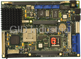
The SBC-MediaGX is a high-performance, high-functionality multimedia PC/AT compatible
processor board designed to be embedded into OEM equipment. It contains all the standard
features found in a PC/AT system with some embedded and multimedia additions. These
include silicon disk drive, Ethernet, 16-bit SoundBlaster, PC/104-Plus expansion bus, MMX-
enhanced CPU and high performance flat panel VGA controller.
Once you have completed development the board can be purchased in the following standard
variants:-
SBC-MediaGX-233-M0-F0 233MHz CPU, No DRAM, No Flash
SBC-MediaGX-233-M0-F8 233MHz CPU, No DRAM, 8MB Flash
SBC-MediaGX-233-M32-F0 233MHz CPU, 32MB DRAM, No Flash
SBC-MediaGX-233-M32-F8 233MHz CPU, 32MB DRAM, 8MB Flash
Other memory and flash variants may be available including:-
F4 - 4MB Flash
F16 - 16MB Flash
M64 - 64MB DRAM
M128 - 128MB DRAM
Contact Arcom Control systems sales for pricing and availability.
Revision History
Manual PCB Comments
Issue A V1 Iss3 990611 Initial Release
Issue B V1 Iss3 990715 [ECO 2830]
Page 5
CONTROL SYSTEMS
2192-10048-000-000 J629 SBC-MediaGX
Features
• CPU:
� National/Cyrix MediaGX 233MHz MMX-enhanced processor
• Chipset:
� National/Cyrix CX5530 I/O Companion
• Cache:
� 16K L1 write-back cache
• BIOS
� Award Software PCI Plug and Play BIOS in Flash EPROM
� Intel/Chips & Technologies 69000 HiQVideo BIOS
� Onboard reprogramming
• System Memory:
� Up to 128MB Unbuffered 3.3V SDRAM
• Silicon Disk
� Up to 16MB Intel Strata Flash
� Datalight FlashFX Flash filling system.
• Video:
� Intel/Chips and Technologies 69000 HiQVideo Controller
� 2MB integrated SDRAM
� XVGA for CRT and Flat panel displays
� 32-bit PCI Local bus interface
� VGA BIOS integrated into system ROM
� Simultaneous CRT and Flat panel display
• Integrated I/O
� NS97317 with built in Real Time Clock and Keyboard controller.
• Audio
� Cyrix XpressAAUDIO 16-bit SoundBlaster compatible.
� National LM4548 CODEC.
� Line IN, Line OUT and Microphone
• Enhanced IDE
� Bus Mastering mode, up to two devices
� Supports PIO Mode 4 or Ultra DMA/33 Hard Disk and ATAPI CD-ROM
• FDD Interface
� Supports two floppy drives 360KB, 720KB, 1.2MB, 1.44MB, 2.88MB
• Parallel Port
� High speed parallel port SPP/EPP/ECP mode.
� BIOS Configurable
• Serial Ports
� Four 16C550 compatible high speed UART's
� 3 x RS232 and 1 x RS232/422/485 Interfaces
Page 6
CONTROL SYSTEMS
J629 SBC-MediaGX 2192-10048-000-000
• USB Interface
� Two Universal Serial Bus (USB) interfaces
• Touchscreen
� 4 wire analogue resistive touchscreen controller
• Network support
� Realtek RTL8139A 10/100-BASETX Ethernet controller
� 32-bit PCI interface
• Expansion
� PC/104-Plus expansion bus
� 8/16 bit ISA compatible interface
� 32-bit PCI compatible interface
• Software Compatibility
� Datalight ROM-DOS operating system license supplied with each board
� Windows 95/98/NT/CE, Linux, QNX
� Other 80x86 compatible software applications.
• Size
� EBX Compatible footprint 5.75" x 8.00" (146mm x 203mm)
Page 7
CONTROL SYSTEMS
2192-10048-000-000 J629 SBC-MediaGX
Getting Started
The development kit contains a "Quickstart" manual that has been designed to enable users
to set-up and start using the board as soon as possible. You should read this manual and follow
the steps defining how to set-up the board. Once you have completed this task you will have
a working SBC-MediaGX system and can start adding other peripherals to enable you to start
development.
The section below has been designed to guide you through setting up and using some of the
features of the SBC-MediaGX. If you would like more detailed information on any aspect of the
board refer to the "Detailed Hardware Description" section of this manual.
Using the SBC-MediaGX
The SBC-MediaGX uses an Award Software PCI BIOS (Basic Input-Output System) to provide
support for the board. The BIOS has a built-in setup program that allows users to modify the
basic system configuration. The setup program can be invoked during the power on sequence
by pressing the key when prompted or by pressing key during the POST routine. The USB
function is enabled/disabled in the 'Chipset Features' menu. Once this device has been
enabled the PCI Plug and Play BIOS will set up the control registers and the device will be
available for use. The standard USB connector is a 4 way socket which provides power and
data signals to the USB peripheral. The 10-way header PL8 has been designed to be
compatible with PC expansion brackets which support two USB sockets (Refer to the USB
section in this manual and Appendix A for more details).
Page 12
CONTROL SYSTEMS
J629 SBC-MediaGX 2192-10048-000-000
The USB device will be supplied with a driver that must be installed to enable the device to be
used (Refer to the documentation supplied with the device).
Using the Ethernet Interface
The Realtek RTL8139A Ethernet controller will be configured by the Award Plug and Play BIOS
during the POST process. Drivers for various operating systems are supplied on the support
CD-ROM, the appropriate driver must be loaded before the ethernet interface can be used.
Connection is made via the 8 way RJ45 connector PL1. A second connector PL6 provides
outputs that can be used to control LED's for TX, RX and LINK status.
Page 13
CONTROL SYSTEMS
PL22
2192-10048-000-000 J629 SBC-MediaGX
Links and Connectors
Links
There are thirteen user selectable links on the SBC-MediaGX. The following section provides
details on these links. The '+' sign indicates the default position for each link.
Page 14
CONTROL SYSTEMS
PL18
PL19
PL20
DIMM 1
PL1
PL2
PL4
PL3
PL5
A
LK1
B
PL6
LK2
LK4
IC6
LK3 LK5 LK6
PL10
PL14
PL15
PL16
IC11 B
LK8
LK7
LK9
A
IC17
LK10
B A
PL21 LK11
LK12
PL23
B A
PL26 PL24
LK13
PL28
PL27
PL25
J629 SBC-MediaGX 2192-10048-000-000
LK1 - COM3 Signal assignment.
COM3 can be used to support either a standard RS232 serial interface or the onboard
touchscreen controller interface. This link has been provided to select between these two
functions.
LK1-1 LK1-2 Description
A+ A+ RS232 Interface selected
A B Not valid combination
B A Not valid combination
B B Touchscreen Controller Interface selected
LK2 - COM3 IRQ routing
This link is used to select which IRQ signal is connected to the COM3 serial port.
LK2 Description
A IRQ4
B + IRQ11
LK3 - COM4 IRQ routing
This link is used to select which IRQ signal is connected to the COM4 serial port.
LK2 Description
A IRQ3
B + IRQ10
LK4, LK5 and LK6 - RS485/422 configuration
These links are used to configure the RS485/422 serial interface. They can be used to
enable/disable the RS485 receive buffer and RS485/422 line termination (See ‘RS485/422’
section for more details).
LK4 Description
Fit+ RS422 termination resistor connected
Omit RS422 termination resistor disconnected
LK5 Description
Fit RS485 Receiver enabled
Omit+ RS485 Receiver disabled
LK6 Description
Fit+ RS485 termination resistor connected
Omit RS485 termination resistor disconnected
Page 15
CONTROL SYSTEMS
2192-10048-000-000 J629 SBC-MediaGX
LK7 - Watchdog Timer Enable
This link has been provided to enable/disable the watchdog function. When the link is in the
enable position the watchdog timer can be started by writing to I/O location 93H (See the
‘Watchdog Timer’ section for more details).
LK7 Description
Fit Enabled
Omit+ Disabled
LK8 - Watchdog Timer timeout selection
The watchdog timer has two pre-configured timeout delays, these are either 2 or 8 seconds.
This link can be used to select between the two timeout periods.
LK8 Description
Fit 2 second timeout
Omit+ 8 second timeout
LK9 - Clear CMOS/ Battery disable
A battery link is fitted that is used to prevent drain on the battery during shipment. This link can
also be used to clear the contents of the CMOS RAM.
LK1 Description
A Battery Backup enabled
B + Battery Backup Disabled (CMOS RAM cleared)
LK10 - LCD Backlight Supply Voltage
This link has been provided to enable selection of the LCD backlight supply voltage
(BLKSAFE). Two options are available either +5V or +12V (Note:- If +12V is selected this
voltage must be supplied from an external source via the power connector PL9).
LK10 Description
A+ +5V Backlight
B +12V Backlight
LK11 - LCD Panel power supply voltage
This link has been provided to enable selection of the LCD panel supply voltage (VDDSAFE).
Two options are available either +5V or +3.3V.
LK11 Description
A+ +5V Supply
B +3.3V Supply
Page 16
CONTROL SYSTEMS
J629 SBC-MediaGX 2192-10048-000-000
LK12 & LK13 - User Links
These two links are user configuration links. They have no function on the SBC-MediaGX, but
can be used by an application program to signify configuration setting. The position of these
links can be read via the special function I/O register at address 259H (See the ‘User Link’
section for details).
LK12 Description
Fit+ Bit 1 of 259H ‘Logic 1’
Omit Bit 1 of 259H ‘Logic 0’
LK13 Description
Fit+ Bit 2 of 259H ‘Logic 1’
Omit Bit 2 of 259H ‘Logic 0’
Connectors
There are twenty eight connectors on the SBC-MediaGX that allow you to connect external
devices such as keyboard, floppy disk drives, hard disk drives, printers etc. Detailed pin
assignments are shown in Appendix A.
Connector Description
PL1 Ethernet Interface
PL2 COM3 RS232 Serial Port
PL3 COM4 RS232 Serial Port
PL4 COM4 RS422/485 Serial Port
PL5 CPU Fan Power
PL6 Ethernet Controller Status LED’s
PL7 PS/2 Keyboard
PL8 USB Serial Port
PL9 PS/2 Mouse
PL10 PC/104-Plus Expansion
PL11 4-wire Analogue Resistive Touchscreen
PL12 EBX Power Supply Connector
PL13 General Purpose I/O
PL14 Reset Switch
PL15 Suspend/Resume Switch
PL16 PC Speaker
PL17 Parallel Port Interface
PL18 Floppy Disk Interface
PL19 COM2 RS232 Serial Port
PL20 COM1 RS232 Serial Port
PL21 VGA CRT Interface
PL22 IDE Interface
PL23 64-way PC/104 Expansion
PL24 Flash Access LED
PL25 In-System-Program header
PL26 40-way PC/104 Expansion
PL27 Audio Functions
PL28 VGA Flat Panel Interface
Page 17
CONTROL SYSTEMS
2192-10048-000-000 J629 SBC-MediaGX
AWARD BIOS SETUP
The Award BIOS ROM has a built-in Setup program that allows users to modify the basic
system configuration. This type of information is stored in battery-packed RAM so that it retains
the Setup information when the power is turned off.
ENTERING SETUP
Power on the computer and press immediately will allow you to enter Setup. The other
way to enter Setup is to power on the computer, when the below message appears briefly at
the bottom of the screen during the POST (Power On Self Test), press key of
simultaneously press keys.
Control Keys
Up Arrow Move to previous item
Down Arrow Move to next item
Left Arrow Move to the item in the left hand
Right Arrow Move to the item in the right hand
Esc Key Main Menu Quit and not to save changes to CMOS
Status Page setup menu and Option Page
Setup Menu Exit current page and return to Main Menu
PgUpKey Increase the numeric value or make changes
PgDnKey Decrease the numeric value or make changes
F1 Key General help, only for Status Page Setup
Menu and Option Setup
Menu
F2 Key Change colour from total 16 colours
F3 Key Calendar, only for Status Page Setup Menu
F4 Key Reserved
F5 Key Restore the previous CMOS value from BIOS, only for Option
Page Setup Menu
F6 Key Load the default CMOS value from BIOS default table, only for
Option Page Setup Menu
F7 Key Load the default
F8 Key Reserved
F9 Key Reserved
F10 Key Save all the CMOS changes, only for Main Menu
Page 18
CONTROL SYSTEMS
J629 SBC-MediaGX 2192-10048-000-000
GETTING HELP
MAIN MENU
The on-line description of the highlighted setup function is displayed at the bottom of the
screen.
Status Page Setup Menu/Option Page Setup Menu
Press F1 to pop up a small help window that describes the appropriate keys to use and
the possible selections for the highlighted item. To exit the Help Window press key. In the
'BIOS Features' screen set boot sequence to CD-ROM, C, A and in the 'Chipset Features'
screen enable USB support if required. Exit Setup and save changes.
Insert the Windows 98 CD into the drive and reboot the system.
A prompt will appear to enable you to start installing Windows 98. Complete installation as
described in the Windows 98 user manual. After installation the following drivers can be
installed.
Page 36
CONTROL SYSTEMS
J629 SBC-MediaGX 2192-10048-000-000
Installing Cyrix MediaGX drivers
Using the Run command on the Start menu select the following file from the support CD-ROM
D:\Windows9x\Cyrix MediaGX Certified Win9x Drivers 4.0
You will be prompted for the Windows 98 CD when required.
If you are asked to insert the disk labelled 'XpressAUDIO™ driver disk' insert the support CD
and supply the path:-
D:\Windows\Audio 5.05.00.1005
Installing the Chips HiQ 69000 Video driver
Restart Windows when prompted. The XpressAUDIO and PCI Bridge will be detected when
the operating system loads.
Using the Run command on the Start menu select the following file from the support CD-ROM
D:\Windows9x\98 Display 6.0.0\w98600
Restart Windows when prompted to ensure the driver is detected.
Installing RealTek Ethernet Drivers
Choose PCI Ethernet Controller from the system icon in 'Control Panel'. Select 'Properties
General' and select 'Reinstall Driver'. Select 'Search for a driver from specified location' and
specify:-
D:\Ethernet\Win98
When prompted for the location of the .CAB file enter
D:\Ethernet\Win98
The Windows 98 installation CD may be required to complete installation. Restart Windows
98 when prompted.
Windows NT4.0 Driver Support
Before installing Windows NT 4.0 power up the board and enter Setup using the key.
In the 'BIOS Features' screen set boot sequence to CDROM, C, A .Exit Setup and save
changes.
Insert the Windows NT 4.0 CD into the drive and reboot the system.
The CD-ROM will be detected as
IDE CD-ROM (ATAPI 1.2)/PCI IDE Controller
You do not need to select any additional SCSI adapters, CD-ROM drives or special disk
controllers.
Install NT 4.0 on an NTFS partition. When prompted ,select 'Do not connect this computer to
a network at this time' and leave the video controller configured as standard VGA. If you would
like to install Windows NT 4.0 Service pack 4. Select the following file form the support CD-
ROM once NT 4.0 has completed installation.
D\NT4SP4\SP4I386.EXE
Page 37
CONTROL SYSTEMS
2192-10048-000-000 J629 SBC-MediaGX
Installing Cyrix Audio drivers
Insert support CD-ROM in drive and from the Start menu select 'Control Panel' ->'Multimedia'
and 'Devices'. Select 'Audio' and then 'Add' followed by 'Unlisted or Updated Driver'. Enter
the following path:-
D:\Windows NT4\Audio 1.0
Select the 'XpressAUDIO™ Driver'. This driver does not autodetect the hardware, therefore
the I/O, IRQ and DMA settings must be identical to those specific in the BIOS Setup screen.
Default values are
Audio I/O Base Address 220H
MPU-401 I/O Base Address 330H
Audio IRQ Select IRQ5
Audio Low DMA Select DMA 1
Audio High DMA Select DMA 5
Installing Chips HiQ 69000 Video Drivers
Insert support CD-ROM in drive and from the Start menu select 'Control Panel' then select
'Display'->'Settings'->'Display Type' and 'Change'. Select 'Have Disk' and enter the following
path:-
D:\Windows NT4\Display 1.2.9
Select the OEMSETUP>INF file, this will start installation of the Chips 69000 Video drivers.
When prompted restart Windows NT.
Install RealTek Ethernet Drivers
Create a new directory on your NT drive (i.e. C:\Ethernet)and copy the contents of the
following directory on the support CD-ROM:-
D:\Ethernet\Winnt\*.*
From the Start menu select 'Control Panel' and 'Network'. Select 'Wired to the Network',
choose 'Select from List' and 'Have Disk'.
Enter the path of your new directory.
Select 'The RTL8139 Fast Ethernet Adapter'. Select the protocols you require. When
prompted insert the Windows NT installation CD-ROM into the drive. Complete installation as
described in the Windows NT documentation.
Other Software Support
The support CD-ROM also contains the following material:-
1. Microsoft Internet Explorer 5.0
2. Mitsumi Mouse Driver (For DOS)
3. Adobe Acrobat Reader 3.0
4. Example source code for:-
i) General purpose I/O.
ii) LM75 Temperature monitor.
iii) RS485/422 Serial Communications.
iv) Touchscreen Controller.
Please refer to the documentation on the CD-ROM for the latest information.
Page 38
CONTROL SYSTEMS
J629 SBC-MediaGX 2192-10048-000-000
Hardware Support Information
As the SBC-MediaGX is a fully compatible PC/AT processor board any standard PC reference
guide will provide information on hardware aspects of the board. The following material has
been included on the support CD-ROM as it relates to specific features of the board which may
not be available from other sources. This information is stored in the REFERENCE directory:-
1. National /Cyrix MediaGX data sheet.
2. National / Cyrix CX5530 data sheet.
3. Intel/Chips and Technologies 69000 data sheet, OEM reference guide and application notes
4. National Semiconductor NS97317 Super I/O controller data Sheet
5. National Semiconductor LM4548 AC97 Audio CODEC data sheet.
6. National Semiconductor LM75 data sheet.
7. RealTek RTL8139A data sheet.
8. Intel Strata Flash Data Sheet.
9. PC/104 Specification.
10. PC/104-Plus Specification.
11. EBX Specification.
If you are trying to locate information on a specific function which is not included above then
refer to Appendix E which contains references to some relevant internet sites.
Please refer to the documentation on the CD-ROM for the latest information.
Page 39
CONTROL SYSTEMS
2192-10048-000-000 J629 SBC-MediaGX
Detailed Hardware Description
The following section provides a detailed description of the functions provided by the SBC-
MediaGX. This information may be required during development once you have started adding
extra peripherals or are starting to use some of the embedded features.
Processor
The National/Cyrix MediaGX processor is an MMX-Enhanced Pentium class processor. It has
been designed to provide a low power, low cost fully integrated PC/AT compatible system . The
MediaGX is a 64-bit x86 compatible device and has 16K L1 write-back cache integrated into
the processor. The device also contains an integrated floating point unit. A 233MHz part is
used on the SBC-MediaGX, this part is supplied with a 33MHz clock signal and multiplied
within the device.
The processor has two supply rails the core is powered from a +2.9V source and the I/O is
powered from +3.3V. These voltages are generated on the SBC-MediaGX from the main +5V
supply input.
Along with the CX5530 I/O companion chip the MediaGX provides a Synchronous DRAM
controller, VGA Video Controller, PCI 2.1 compatible bus controller, 32-bit IDE controller,
SoundBlaster compatible audio device, PCI-ISA bus bridge, standard ISA bus motherboard
peripherals and a dual USB controller.
The MediaGX processor is packaged in a standard Socket 7 compatible Pin Grid Array, but is
not pin-pin compatible with any other Socket 7 device. Therefore this board will not support any
other processor from an alternative manufacturer. The board will always be supplied with a
processor and heatsink fitted to the board, and will be configured for the correct clock multiplier
and voltage settings.
The MediaGX processor is a low power device, a passive heatsink has been used to support
this device on the SBC-MediaGX. This heatsink provides the correct cooling to enable the
processor to operate at ambient temperatures up to 60ºC.
Memory
The SBC-MediaGX supports three types of memory device, the system memory that is
provided by a Synchronous DRAM module, the BIOS EPROM and the Flash EPROM array.
Synchronous DRAM Interface
A single 168-pin Dual-In-Line Memory Module (DIMM) socket is used to support up to 128M
bytes of synchronous DRAM. This interface is designed to support 16MB, 32MB 64MB or
128MB modules which are 3.3V compatible and meet the PC100 timing specification. The
DIMM socket is designed to ensure that only the correct type of memory is installed.
The Award BIOS will automatically detect the amount of memory inserted into this socket
during the power up process and set the appropriate registers correctly with the MediaGX
processor. The BIOS can also be configured to perform an exhaustive test on this memory
during the POST process to ensure it is functioning correctly. This will cause the boot time to
be increased and may be disabled if this is important.
Page 40
CONTROL SYSTEMS
J629 SBC-MediaGX 2192-10048-000-000
BIOS EPROM
A 256K byte Flash EPROM device is used to store the BIOS code. This device can be
reprogrammed in suit using the AWDFLASH utility supplied on the support CD-ROM (See the
‘Software Support’ section for details). The BIOS stored in this device is compressed to save
space and is uncompressed during the power up process. The system BIOS is copied into
shadow RAM between 0E0000H and 0FFFFFH, and the VGA BIOS is copied to 0C0000H.
The flash device is a +5V only device and there are no link settings required to enable
programming.
Flash Memory/Silicon Disk
The SBC-MediaGX board supports up to 16Mbytes of flash memory. This memory is
configured to be a read/write silicon disk drive. The Datalight FlashFX flash filling system will
automatically be loaded during the POST routine to enable the flash drive to be accessed. The
flash drive uses a 16K memory window at 0DC000-0DFFFF to access the devices and two I/O
address locations are used to select the appropriate flash area. The I/O registers are shown
below for information, under normal circumstances the FlashFX driver should be used to
access this memory. The FLASH status LED will illuminate whenever the Flash drive is
accessed.
258H I/O Write
Bit No. Paged Address Register 0
0 Address Bit A14
1 Address Bit A15
2 Address Bit A16
3 Address Bit A17
4 Address Bit A18
5 Address Bit A19
6 Address Bit A20
7 Address Bit A21
259H I/O Write
Bit No. Paged Address Register 1
0 Address Bit A22
1 Address Bit A23
2 No function
3 No function
4 No function
5 No function
6 No function
7 Flash Reset/Power down
Bit 7 0 = device is reset/powered down
1 = device is enabled
Page 41
CONTROL SYSTEMS
2192-10048-000-000 J629 SBC-MediaGX
259H I/O Read
Bit No. Paged Address Register 1
0 Flash Busy Signal (0 = BUSY)
1 User link 1 LK12
(0 = CLOSED, 1 = OPEN)
2 User link 2 LK13
(0 = CLOSED, 1 = OPEN)
3 No function
4 No function
5 No function
6 No function
7 No function
These two registers will be reset to 00h (write) on power up/reset. This ensures that the
Register 1 Bit 7 is 0, i.e. Flash is disabled and write protected.
Memory Map
The following table shows the memory map for the SBC-MediaGX.
Address Block Size Description
0FFFC0000H 256K System BIOS ROM
07FFFFFFH - Extended memory limit
(Depending on SDRAM
fitted)
00100000H 127M Extended memory
000E0000H 128K System BIOS ROM and
embedded SETUP
000DC000H 16K FlashFX BIOS extension and
Flash Disk Window
000CC000H 64K Directed to PC/104 bus
000C0000H 48K VGA BIOS extension
000A0000H 128K Video RAM
00000000H 640K System RAM
Page 42
CONTROL SYSTEMS
J629 SBC-MediaGX 2192-10048-000-000
I/O Map
The PC/AT I/O address map is limited to 1K addresses. This is because only the lower ten
address lines were originally used to decode I/O devices. The remaining lines were treated as
undefined. Therefore the usable address range is from 0-3FFH, above this range devices are
imaged and will be accessed throughout the entire 64K I/O address range of the processor.
The following table shows the I/O address mapping for the SBC-MediaGX. If expansion
boards are added via the PC/104 interface you should ensure that they are configured to be at
a free address location. Otherwise they will not function correctly and may even cause the
SBC-MediaGX board to stop operating.
Device I/O Location (Hex)
DMA Controller 1 000-00F
Interrupt Controller 1 020-021
Timer/Counter 040-043
Keyboard/Mouse 060-064
Real Time Clock 070-071
DMA Page Registers 080-08F
Watchdog Timer 093
Interrupt Controller 2 0A0-0A1
DMA Controller 2 0C0-0DF
Audio 220-22F
Flash Paging Registers 258-259
RS232 Power-down Latch 260
COM4 2E8-2EF
COM2 2F8-2FF
MPU-401 330-33F
Parallel Port 378-37F
Video Controller 3B0-3BB, 3C0-3CF, 3D0-3DF
COM3 3E8-3EF
Floppy Disk 3F0-3F7
COM1 3F8-3FF
Page 43
CONTROL SYSTEMS
2192-10048-000-000 J629 SBC-MediaGX
Graphics Controller
An Intel/Chips and Technologies 69000 HiQVideo graphics controller is integrated onto the
SBC-MediaGX. This device is used to provide a high performance flat panel/CRT video
controller.
The flat panel display output can be used to support monochrome single scan STN, dual scan
STN, TFT, EL and Plasma displays. The TFT output can be used to support up to 36 bit
displays.
The 69000 contains 2M bytes of synchronous DRAM included within the device. This memory
is used to support the standard VGA frame buffer and can be used to provided an extra buffer
when driving a dual scan panel to synchronise the display data.
The following table shows the video resolutions supported by the 69000 with the corresponding
number of bits per pixel.
Resolution Bit Per Pixel
640 x 480 8/16/24
800 x 600 8/16/24
1024 x 768 8/16
1280 x 1024 8
The flat panel and CRT interface signals are routed to two separate connectors, both displays
can be driven simultaneously. The ability to drive both displays is dependant on the particular
timing parameters of the flat panel display. It is not always possible to select appropriate clock
rates to achieve an output on the CRT and flat panel displays.
The CRT output signals are routed to a 16-way 0.1" boxed header PL21. These signals will
normally be connected directly to a VGA compatible CRT monitor. A suitable cable is provided
as part of the SBC-MediaGX development kit. The following table shows the connection details
for this cable. The CRT signals may be affected by noise and therefore this cable should be
keep as short as possible and should be routed away from other signals to stop any crosstalk.
PL21 Pin Signal Name 15 way D-Type
High Density
1 RED 1
2 Ground 6
3 GREEN 2
4 No Connection 4
5 BLUE 3
6 Ground 7
7 No Connection 9
8 No Connection 11
9 Ground 8
10 Ground 5
11 Ground 10
12 HSYNC 13
13 No Connection 12
14 VSYNC 14
15 No Connection 15
16 No Connection -
Page 44
CONTROL SYSTEMS
J629 SBC-MediaGX 2192-10048-000-000
The flat panel signals are routed to a 68 way Thomas & Betts SYSTEM311 high-density
connector (PL28). These signals provide the flat panel data and control signals. The flat panel
interface can be configured to drive various types of panel. Each interface redefines the
function of the panel data lines.
The following table provides a cross reference between the flat panel output signals and their
function when configured for different displays.
Mono Mono Mono Colour Colour Colour Colour Colour Colour Colour Colour Colour
SS DD DD TFT TFT TFT TFT- STN- STN- STN- STN- STN-
HR SS SS DD DD DD
8-Bit 8-Bit 16- 9/12/16 18/24 36 Bit 18/24- 8-Bit 16-Bit 8-Bit 16-Bit 24-Bit
Pin
Bit Bit Bit Bit (4bp) (4bp) (4bp) (4bp)
Name
P0 D0 UD3 UD7 B0 B0 FB0 FB0 R1 R1 UR1 UR0 UR0
P1 D1 UD2 UD6 B1 B1 FB1 FB1 B1 G1 UG1 UG0 UG0
P2 D2 UD1 UD5 B2 B2 FB2 FB2 G2 B1 UB1 UB0 UB0
P3 D3 UD0 UD4 B3 B3 FB3 FB3 R3 R2 UR2 UR1 LR0
P4 D4 LD3 UD3 B4 B4 FB4 SB0 B3 G2 LR1 LR0 LG0
P5 D5 LD2 UD2 G0 B5 FB5 SB1 G4 B2 LG1 LG0 LB0
P6 D6 LD1 UD1 G1 B6 SB0 SB2 R5 R3 LB1 LB0 UR1
P7 D7 LD0 UD0 G2 B7 SB1 SB3 B5 G3 LR2 LR1 UG1
P8 LD7 G3 G0 SB2 FG0 B3 UG1 UB1
P9 LD6 G4 G1 SB3 FG1 R4 UB1 LR1
P10 LD5 G5 G2 SB4 FG2 G4 UR2 LG1
P11 LD4 R0 G3 SB5 FG3 B4 UG2 LB1
P12 LD3 R1 G4 FG0 SG0 R5 LG1 UR2
P13 LD2 R2 G5 FG1 SG1 G5 LB1 UG2
P14 LD1 R3 G6 FG2 SG2 B5 LR2 UB2
P15 LD0 R4 G7 FG3 SG3 R6 LG2 LR2
P16 R0 FG4 FR0 LG2
P17 R1 FG5 FR1 LB2
P18 R2 SG0 FR2 UR2
P19 R3 SG1 FR3 UG3
P20 R4 SG2 SR0 UB3
P21 R5 SG3 SR1 LR3
P22 R6 SG4 SR2 LG3
P23 R7 SG5 SR3 LB3
P24 FR0
P25 FR1
P26 FR2
P27 FR3
P28 FR4
P29 FR5
P30 SR0
P31 SR1
P32 SR2
P33 SR3
P34 SR4
P35 SR5
SHF SHF SHF SHF SHF SHF SHF SHF SHF SHF SHF SHF SHF
CLK CLK CLK CLK CLK CLK CLK CLK CLK CLK CLK CLK CLK
Pixels/ 8 8 16 1 1 2 2 2-2/3 5-1/3 2-2/3 5/1/3 8
Clock
Page 45
CONTROL SYSTEMS
2192-10048-000-000 J629 SBC-MediaGX
The display signals are +3.3V compatible and may be used to drive +5V panels, the input
threshold level on the display should be verified to ensure it is compatible. If the display needs
higher level signals then the panel data may be buffered off board by +3.3V to +5V translators.
The SBC-MediaGX contains power control circuitry for the flat panel and backlight controller
supplies. The flat panel can be supplied with a switched +3.3V or 5V supply depending on the
position of LK11, and the backlight controller can be supplied with either +5V or +12V
depending on the position of LK10 (See the ‘link’ section for details).
The supply voltages are controlled by the 69000 during power up/down, to ensure that the
panel is not damaged due to the input signals being incorrectly configured. The backlight can
also be switched ON/OFF during normal operation to preserve the life of the tube.
The flat panel signals are configured by the VGA BIOS during the power up process. The
default BIOS is designed to drive the 6.5" NEC TFT panel that is supplied as part of the flat
panel development kit. If you are using a different type of panel then the BIOS will need to be
modified to configure the device correctly. The support CD-ROM contains BIOS image files for
flat panel displays that have been tested by Arcom Control Systems. These images can be
programmed into the BIOS EPROM using the AWDFLASH utility (See the ‘Software Support’
section for details). The CD-ROM also contains connection information for each of these
displays.
If the display you wish to use in your application is not listed on the CD-ROM, then contact
Arcom Control Systems technical support at support@arcom.co.uk as the list of displays is
continually updated.
The support CD-ROM contains drivers for Windows 3.11, Windows 95, Windows 98 and
Windows NT 4.0. Other drivers may be available from the Intel internet site at www.intel.com.
The drivers supplied can be used to support standard video orientation as well as portrait mode
for some operating systems.
Interrupt Assignments
The SBC-MediaGX233 contains two 8259 interrupt controllers, which are cascaded in the
standard PC/AT compatible format. The table below shows the IRQ routing of the on-board
devices.
IRQ Usage
0 8254 Timer
1 Keyboard
2 Cascade
3 COM2/COM4
4 COM1/COM3
5 Audio Controller
6 Floppy Disk
7 Printer
8 Real Time Clock
9 Unassigned
10 Ethernet/COM4
11 69000 VGA/COM3
12 Mouse
13 Coprocessor
14 IDE
15 Universal Serial Bus (USB)
Page 46
CONTROL SYSTEMS
J629 SBC-MediaGX 2192-10048-000-000
These IRQ signals are routed to the PC/104 interface as well as the onboard devices. PC/104
boards can only use these signals if they are unassigned or the onboard device is disabled.
Some of the interrupt lines are connected to PCI devices on board these are the Ethernet
controller, VGA controller and USB device. During the Plug and Play BIOS configuration these
devices are configured to use an available IRQ line. The table shows the default IRQ routing
for these devices. If the devices are disabled or an adapter card is plugged into the PC/104-
Plus interface which requires an interrupt this routing may change.
Before using these interrupts check that the appropriate line is not already configured for
another device. If you need to free up a particular interrupt it may be possible by setting the
'PNP/PCI Configuration' in the BIOS setup screen. If an interrupt line is selected to support
'Legacy ISA mode' it will not be used by the Plug and Play BIOS and will remain free for ISA
bus use. This will normally only apply to IRQ lines that are greater than IRQ9 as the lower order
interrupts are already assigned to ISA bus devices.
Care should be taken when configuring these interrupts as you may find that particular
combinations do not provide a working solution. This may be due to two or more PCI devices
being routed to the same IRQ line. Although this is allowable in the PCI specification, not all
device drivers provide the ability to share the interrupts.
DMA Controller
There are two 8237 DMA controllers on the SBC-MediaGX. These controllers are cascaded in
a standard PC/AT style. DMA channels 0-3 are used to support 8-bit devices and DMA
channels 4-7 support 16-bit devices. DMA channel 4 is used to provide cascading between the
two controllers and therefore is unavailable for use. The table below shows the default
assignment for the DMA channels on the SBC-MediaGX.
DMA Usage
0 Unassigned
1 Audio Controller
2 Floppy Disk Interface
3 Parallel Port (ECP Mode)
4 Cascade
5 Audio Controller
6 Unassigned
7 Unassigned
The DMA signals are routed to the PC/104 interface as well as the onboard devices. They may
only be used if they are unassigned or the onboard peripheral is disabled.
IDE Interface
The SBC-MediaGX has a single Integrated Drive Electronics (IDE) controller that supports up
to two hard disk drives. The disk drives are connected via a 1:1 40-way ribbon cable using
PL22. One drive must be configured as a 'MASTER' and the other drive as a 'SLAVE'. An IDE
compatible CD-ROM drive can also be used and should be configured as the 'SLAVE' device.
The BIOS will automatically detect which devices are connected via this interface and
configure the controller correctly. The BIOS can be configured to make either the hard disk
drive or CD-ROM the default boot device.
If a hard disk drive is attached to this interface the default configuration will cause the drive to
be used as the standard boot device and the flash disk if present will become the next available
drive.
Page 47
CONTROL SYSTEMS
2192-10048-000-000 J629 SBC-MediaGX
The IDE controller is a 32-bit PCI device and supports Ultra DMA/33 mode of operation. The
IDE controller also supports Bus Mastering mode and a suitable driver is supplied on the
support CD-ROM. The 32-bit interface provides a much faster access speed than the original
ISA style interface.
Floppy Disk Controller
The floppy disk interface is designed to support up to two standard floppy disk drives.
Connections are made via a 34-way 0.1" boxed header PL18 (See Appendix A for pin
assignment details). All standard capacities including 360KB, 720KB, 1.2MB,1.44MB and
2.88MB are supported. The BIOS must be configured appropriately for the desired format
using the Setup program. The default BIOS configuration supports a single 1.44MB floppy disk
drive configured as DRIVE A: and if this drive contains a bootable floppy when the board is
powered up it will be used as the default boot device. If no drive is present the BIOS will
continue to operate correctly.
The floppy disk drive cable should have three connectors, two which are connected directly 1:1
and one which has pins 10-16 twisted. If only one drive is required it should be connected via
the twisted cable and the drive should be setup to use drive select 1. If two drives are required
the second drive should also be configured for drive 1 but should be connected via the straight
connector. This connection does not provide power and therefore a separate cable from the
main supply should be used.
The floppy disk interface is decoded in I/O address space at 3F0-3F7H and uses IRQ6 and
DMA channel 2.
Real Time Clock (RTC)
The Real Time Clock (RTC) is fully compatible with the PC/AT standard clock device. The date
and time functions are stored in the real time clock when the main power is removed if the
battery backup supply is enabled (See LK3 description). As well as providing time and date
information the Real Time Clock is used to store the BIOS settings. The RTC is decoded in I/O
address space at 70-71H and is connected to IRQ8. The RTC registers are accessed via an
indexed addressing mechanism. I/O location 70 is used to select the appropriate register and
71H is used to access the data.
The maximum rated current for the RTC is 2uA and the battery backup supply is provided by
a Lithium coin cell with a capacity of 180mA. This battery will provide sufficient support for at
least 10 years. The battery is disabled during shipment to prolong the useful life. If the board
is going to be placed out of service for long periods of time then the battery should also be
disabled. If the main supply is present on the board the battery automatically gets disconnected
from the RTC circuitry.
The accuracy of the RTC is based on the operation of the 32.768KHz watch crystal. This will
provide an accuracy of – 1 minute per month if the board is in an ambient environment of
”
+25C. When the board is operated outside this temperature then the accuracy may be
degraded.
Keyboard/Mouse Controller
An 8042 compatible keyboard controller provides support for a standard PC/AT keyboard and
mouse. Both interfaces use a 6-pin mini-DIN style connector, the keyboard is connected via
PL7 and mouse via PL9. The keyboard controller is decoded at I/O address location 60-64H
and uses IRQ1 for keyboard and IRQ12 for mouse support. Power for the keyboard and mouse
is sourced form the +5V supply and a resettle fuse protects the board if either interface is short
circuited.
Page 48
CONTROL SYSTEMS
J629 SBC-MediaGX 2192-10048-000-000
The development kit is supplied with a PS/2 to AT adapter cable that can be used to convert
between the mini-DIN connector and the standard AT style connector. The development kit
also contains a PS/2 mouse that will plug directly into PL9.
The Award BIOS will automatically detect the presence of the keyboard and mouse and
provide support. If these devices are not plugged in the BIOS will continue to operate correctly.
Ethernet Controller
A RealTek RTL8139A Ethernet controller provides 10/100-BASETX interface. This is a 32-bit
PCI device that is configured by the Plug and Play BIOS during power ON. The device provides
compliance with IEEE802.3u 100BASE-T specification and IEEE 802.3x Full Duplex Flow
Control.. A 93C46 EEPROM is used to store configuration data and ID information.
An 8-way RJ45 connector is used to provide signals (See Appendix A for pin assignment
details).
A second connector PL6 also provides users with status signals that are designed to drive
LED's. The status lines provide TX, RX and LINK status. The output lines sink current when
switched ON therefore the anode of each device should be connector to PL6 pin 1 and the
cathode to the appropriate status line.
The support CD-ROM contains drivers for most operating systems and network software.
These are stored in the ETHERNET directory.
16-Bit SoundBlaster
The Audio support provided on the SBC-MediaGX is fully compatible with the 16-bit
SoundBlaster interface. This device provides support for stereo Line IN and Line OUT and
mono Microphone input. The SoundBlaster is supported via the Cyrix 'XpressAUDIO™'
software which is built into the BIOS code.
A National Semiconductor LM4548 AC97 Audio CODEC is used to provide the output and mix
signals from the input sources. The CODEC can be used to set the output level of each source
and provide a composite signal. There is no amplifier onboard and the output must be
connected to either active speakers or an amplifier module.
Connection is made via a 10-way 0.1" header PL27 (See Appendix A for pin assignments).
The Audio device is connected to the PCI bus and to ensure backward compatibility it must be
setup to respond to standard audio I/O address mapping and IRQ, DMA signals. The BIOS can
be configured to set the appropriate locations. The following settings are configured in the
BIOS as default. These can be modified during POST by entering setup and selecting the
'Integrated Peripherals' screen.
Audio I/O Base Address 220H
MPU-401 I/O Base Address 330H
Audio IRQ Select IRQ5
Audio Low DMA Select DMA 1
Audio High DMA Select DMA 5
Drivers are supplied on the support CD-ROM for Windows 95, Windows 98 and Windows NT
4.0.
Page 49
CONTROL SYSTEMS
2192-10048-000-000 J629 SBC-MediaGX
Watchdog Timer
The SBC-MediaGX contains a watchdog timer, which can be used to protect against erroneous
software. There are two timeout periods available either 2 or 8 seconds depending on the
position of LK8. The watchdog timer is disabled by a RESET and can be started by performing
an I/O write to location 93H (Any value will cause the timer to start). If another I/O write to this
location is not performed within the timeout period the board will be RESET. Writes must be
continually performed to enable the board to function correctly, there is no software disable
mechanism once the timer is started.
The watchdog timer can be disabled permanently by removing user link LK7. This feature may
be useful during debug/development.
User Links
There are two user links on the SBC-MediaGX LK12 and LK13. The status of these user links
can be read via I/O address 259H bits 1 and 2. If the link is made then the corresponding bit
will be read as a logic '0' (See the link section for further details). These links do not have any
defined function on the board, therefore can be used to select options in the application
program.
USB Interface
There are two Universal Serial Bus (USB) interfaces on the SBC-MediaGX. These interfaces
have been designed to support the Open Host Controller Interface (OpenHCI).
There are four signal lines associated with each USB channel, VBUS, DATA+,DATA- and GND.
A USB power control switch is used to control the power and protect against short circuit
conditions. This can be enabled/disabled by the processor and the USB function needs to be
enabled in the BIOS to ensure that power is supplied to each device. The USB feature is
controlled via the setup program and is displayed in the 'Chipset Features' screen.
PL8
USB Port USB Port
1 2
VBUS
VBUS
DATA-
DATA-
DATA+
DATA+
GND GND
Page 50
CONTROL SYSTEMS
J629 SBC-MediaGX 2192-10048-000-000
If the USB voltage is short circuited or more than 500mA is drawn from either supply the switch
will turn OFF the power supply and automatically protect the device and board. The VBUS
signal is derived from the +5V supply via the SBC-MediaGX.
Windows 98 automatically supports the USB features and Windows 95 can be used if the
appropriate service pack is installed. Drivers will be supplied for the various operating systems
with each USB device.
The USB support in Windows 95 is first-generation and the drivers suffer from various
limitations. Microsoft recommends only using Windows 98 and Windows 2000 if USB support
is required. Most USB peripherals are only supplied with drivers for these operating systems.
If you are looking for details on the USB bus, or would like to determine whether particular
peripherals are available then look at the following internet site www.usb.org.
Touchscreen Controller
The four wire analogue resistive touchscreen interface can be used in place of the standard
COM3 RS232 interface. A user link LK1 is used to select between the RS232 interface
(Position 'A') or the touchscreen interface (Position 'B'), see link section for further details. A
second user link LK2 can also be used to select which IRQ line is used to indicate that a touch
has occurred.
The touchscreen controller contains an 8-bit analogue to digital converter and transmits a
serialised bit stream corresponding to the A/D outputs. Each time the touch panel position is
reported, the X co-ordinate value is transmitted as an unsigned 8-bit value followed by the Y
co-ordinate value, which is also an unsigned 8 bit value. The Y co-ordinate value is then sent
again to distinguish between X and Y values.
The serial data is transmitted in the following format:-
Baud: 4800
Parity: None
Bits: 8
Stop bit: 1
The support CD contains some example source code that can be used as a basis for
driver/application development for Windows 95/98/NT other operating systems.
General Purpose I/O
Eight general purpose I/O lines are provided on the SBC-MediaGX. These lines are routed to
a 20 way 0.1" header PL13. The header provides unbuffered and buffered versions of the lines.
The buffered version can be used to drive higher output current up to 24mA per output than
the unbuffered version.
The I/O lines are connected to GPIO line from the NS97317 Super I/O controller. The table
below shows the relationship between the GPIO lines on the super I/O device and the I/O lines
on PL13.
Page 51
CONTROL SYSTEMS
2192-10048-000-000 J629 SBC-MediaGX
NS97317 GPIO Line PL13 GPIO Line
GPIO20 I/O0
GPIO21 I/O1
GPIO23 I/O2
GPIO24 I/O3
GPIO16 I/O4
GPIO37 I/O5
GPIO12 I/O6
GPIO17 I/O7
The following diagram shows the configuration of each I/O line
+5V
10k
I/O
Ns973127
Bufferd I/O
GPIO Line
PL3
1/8 74HCT244
The NS97317 GPIO lines must be configured using the registers built into the device to ensure
they function correctly. Various features can be programmed for each pin including direction
control and pull up/down resistors. As the GPIO lines also share pins with dedicated functions
these must be disabled if the line is to be used.
The support CD-ROM contains some example 'C' source code that can be used to configure
the signals.
CPU Temperature Sensor
An LM75 temperature monitor IC is located under the CPU socket on the SBC-MediaGX. This
device can be used to monitor the ambient temperature and provide feedback if the
2
temperature rises above a predefined level. The LM75 has an I C bus interface and is
connected to three I/O lines form the Super I/O controller. The following table shows the
connection details:-
NS97317 Line LM75 Signal Name
GPIO10 SDA
GPIO11 SCL
P12 OS
Data sheet's for the LM75 and NS97317 are supplied on the support CD-ROM. There is also
an example program that shows how to configure the device and check the output level. The
output form the LM75 will normally be high, but will go to logic '0' when the threshold level is
reached. The output will stay at logic 'O' until the temperature has fallen below the hysterises
level. This output can be used to slow down the CPU and provide user warning if the ambient
temperature becomes excessive.
Page 52
CONTROL SYSTEMS
J629 SBC-MediaGX 2192-10048-000-000
PC/104-Plus Interface
The PC/104-Plus interface supports 8/16 bit ISA style PC/104 signals and 32-bit PCI style
PC/104-Plus signals. Add on boards can be used to enhance the functionality of the main
board. The PC/104 standard has been adopted by a wide range of companies and boards are
available which support various types of interface. This bus can be used to add digital I/O,
analogue I/O, serial ports, video capture devices, PC CARD interfaces etc.
Any board plugged into this interface will be accessed as if it were part of the main board,
therefore it may conflict with I/O and memory devices onboard if it has not been correctly
configured. Before using an expansion board you should check that it can be configured to
work along side the peripherals already incorporated onboard.
The PC/104 bus signals are fully compatible with the ISA bus electrical timing definitions. Some
IRQ and DMA signal lines may be associated with onboard devices and are therefore are not
free to be used by add on boards.
The PC/104-Plus signals are PCI 2.1 compliant and can be used to interface to 32-bit 33MHz
compatible PC/104-Plus modules. The PC/104-Plus bus supports a maximum of four add on
cards and provides individual clock and some dedicated control signals for each card. Refer to
the PC/104-Plus specification supplied on the support CD-ROM for further details.
Serial Ports
There are four high speed 16550 serial UART's on the SBC-MediaGX. All four channels are
fully software compatible with the 16550 and can be used as standard RS232 serial interfaces.
The table below shows the configuration for each channel.
Port I/O Address IRQ Connector
RS232 RS422/485
COM1 3F8-3FFH IRQ4 PL20 N/A
COM2 2F8-2FFH IRQ3 PL19 N/A
COM3 3E8-3EFH IRQ4 (or IRQ11) PL2 N/A
COM4 2E8-2EFH IRQ3 (or IRQ10) PL3 PL4
The RS232 signals are routed to 10 way 0.1" boxed header which are designed to provide
direct connection to 9 way D-type plugs. The serial ports provide support for various baud rates
up to a maximum of 115Kbaud. The Award BIOS will detect the serial ports during the POST
process and configure the baud rate, data, stop bits etc.
The table above provides details of the IRQ signal associated with each channel. If the
standard IRQ3 and IRQ4 assignments are used then only one of the channels can be
configured to use each interrupt. If your system requires more than two interrupts then the
other ports can be configured to use IRQ10 and IRQ11. These interrupts may be assigned to
PCI devices during the Plug and Play BIOS initialisation. Therefore you should select 'Legacy
ISA' for these interrupts in the 'PNP/PCI Configuration' setup screen.
Note:- COM3 can be used to support either the standard RS232 interface or if the Touchscreen
interface is required then this is accessed via this port (Refer to the ‘Touchscreen’ section for
details).
RS422/485 Interfaces
The COM4 serial interface can be used to support RS232/RS422 and RS485 interfaces. The
default configuration has been selected to enable RS232 operation.
RS422
The RS422 interface provides full duplex communication. The signals available are TXA,
TXB, RXA ,RXB and Ground. The maximum cable length for an RS422 system is 4000ft and
it supports 1 driver and up to 10 receivers. To enable RS422 operation LK5 should be
Page 53
CONTROL SYSTEMS
2192-10048-000-000 J629 SBC-MediaGX
removed and the RTS line from COM4 should be at logic '0'. LK4 and LK6 should be made
if the board is at the end of the network.
RS485
This is a half-duplex interface that provides combined TX and RX signals. PL4 pin 5 provides
TXB/RXB and pin 6 provides TXA/RXA. A ground connection is also required for this
interface. The maximum cable length for this interface is the same as RS422(4000ft), but
RS485 supports up to 32 transmitters and receivers on a single network. Only one transmitter
should be switched on at a time. The SBC-MediaGX uses the RTS signal to control
transmission, when this signal is at logic '1' the driver is switched OFF and data can be
received from other devices. When the RTS line is at logic '0' the driver is ON. Any data which
is transmitted from the SBC-MediaGX will be automatically echoed back to the receiver. This
enables the serial communications software to detect that all data has been sent and disable
the driver when required. LK5 should be made to the enable RS485 interface. LK4 and
Lk6 should be made if the SBC-MediaGX is at the end of the network.
Parallel Port
The parallel port is fully IEEE1284 compatible and provides Standard Parallel Port (SPP),
Enhanced Parallel Port (EPP) and Extended Capabilities Ports (ECP) support. The parallel
port is decoded at I/O address location 378-37FH (LTP1) and uses IRQ7. In ECP mode the
BIOS can be used to select a appropriate DMA channel, the default channel is DMA 3.
The parallel port has built in protection circuitry to protect against powered devices being
connected when the main supply is removed and damaging the device. Each data and control
signal is designed to source/sink 14mA maximum.
The parallel port connector PL17 is a 26 way 0.1" boxed header. The pin assignment of this
connector has been designed to provide 1:1 connection to an IDC 25-way D-Type socket (See
Appendix A for details). The socket will be compatible with a standard PC parallel port
connector.
The parallel port can be used to connect an external printer, tape drive, disk drive, scanner etc.
Power Supply
The SBC-MediaGX is designed to operate from a single +5V +/- 5% (4.75V to +5.25V) supply.
The power connector PL12 has two +5V connection and three ground connections. These
connections are communed on board. PL12 also has a +12V connection defined. This supply
is not required for the SBC-MediaGX under normal operation, but may be used to supply +12V
to the FAN connector, PC/104 stack and BIOS EPROM if required.
Two other supply voltages are present on the board these are +2.9V and +3.3V. These
supplies are required for the CPU core and on board devices. The +3.3V supply is routed to
the PC/104-Plus header to enable it to be used by additional cards, and can be used to power
+3.3V flat panels via PL28.
The +5V supply is monitored automatically onboard and if this supply falls below 4.63V the
board will be placed in RESET. When the power supply rises above this threshold voltage the
board will start to operate again. This power supply monitor will ensure that the board does not
hang if the supply voltage fails at any point.
The BIOS has built in power management which can be enabled by the Setup program during
the POST process. Various aspects of the board can be controlled by the power management
software. The board can be placed in a power down state and woken using external input from
the mouse, keyboard, serial ports, real time clock etc. The power management software is
designed to monitor activity and will start to slow down the CPU and switch OFF functions if
Page 54
CONTROL SYSTEMS
J629 SBC-MediaGX 2192-10048-000-000
long periods of inactivity are detected.
The SBC-MediaGX has a dedicated I/O register that can be used to power down the RS232
serial buffers if they are not required. Each buffer has an individual control line therefore they
can be switched ON and OFF in any combination. The default configuration for these buffers
at power ON is to be enabled. This ensures that the board operates correctly when first
powered. Once running the buffers can be disabled during periods of inactivity. The register is
located at I/O address 260H and the bit definitions are shown in the table below:-
I/O 260H Write
Bit Description Operation
0 Shutdown COM1 0 = Enabled (Default)
1 = Disabled
1 Shutdown COM2
2 Shutdown COM3
3 Shutdown COM4
4 No Function
5 No Function
6 No Function
7 No Function
Page 55
CONTROL SYSTEMS
2192-10048-000-000 J629 SBC-MediaGX
Status LED's
There are three status LED's on-board the following table describes their functions:-
LED
Colour Name Description
1 Red Flash Access Each time the flash array is accessed this LED will
illuminate.
2 Green Power ON during normal operation.
3 Yellow Suspend ON during Suspend Mode, Power LED will extinguish.
PC Speaker
An 8 ohm speaker may be connected to PL16. The speaker can be used to notify the user of
an error condition during POST or normal operation. The speaker output is controller by
counter 2 output of the 8254 counter/timer (Refer to PC software programming guides for more
information).
The speaker output is also fed to the Audio CODEC and will be mixed with the standard audio
output.
Suspend/Resume Switch
If the power management features are enabled the processor will be switched into a suspend
state after a defined period of inactivity. A momentary switch connected between pin 1 and 2
of PL15 will cause the board to return from this suspend state when pressed. Pressing this
switch during normal operation will immediately cause the system to enter the suspend state.
During suspend all CPU operations will be halted and the board will be placed in a low power
state. Once the board comes out of this state execution will continue from the point where it
entered the suspend state.
RESET Switch
A momentary switch may be connected between pin 1 and 2 of PL14. If the switch is pressed
it will cause the board to be reset. All onboard devices will be reinitialised and the BIOS will
start executing from the top of memory. This may be useful during development to restart the
board after a software crash.
CPU Fan Control
The CPU fan connector PL5 can be used to supply power to a +5V or +12V Fan. The centre
pin of this connector is used to source power. The other two pins are connected to ground
when the FAN is switched ON. The BIOS will switch the FAN OFF if the board enters the
suspend mode. Selection between +5V and +12V is performed at assembly time. The default
setting supports a +12V fan.
The SBC-MediaGX uses a passive heatsink as standard and therefore this connector is not
normally used. If the board is going to be used in a particular environment where the ambient
temperature may exceed the current limits a fan may be required. Please contact Arcom
Control Systems technical support for further information.
Page 56
CONTROL SYSTEMS
J629 SBC-MediaGX 2192-10048-000-000
Appendix A - Connector details
PL1 - Ethernet RJ45
8 way RJ45
Pin Signal Name
1 TX+
2 TX-
3 RX+
4 No Connect
5 No Connect
6 RX-
7 No Connect
8 No Connect
PL2 - COM3 RS232 Serial Port
10 pin 0.1" boxed pin header.
Pin Signal Name Pin Signal Name
1 DCD 2 DSR
3 RXD 4 RTS
5 TXD 6 CTS
7 DTR 8 RI
9 GND 10 No Connect
PL3 - COM4 RS232 Serial Port
10 pin 0.1" boxed pin header.
Pin Signal Name Pin Signal Name
1 DCD 2 DSR
3 RXD 4 RTS
5 TXD 6 CTS
7 DTR 8 RI
9 GND 10 No Connect
PL4 - COM4 RS485/422 Serial Port
10 pin 0.1" boxed pin header
Pin Signal Name Pin Signal Name
1 No Connect 2 No Connect
3 Ground 4 Ground
5 TXB/(RXB 485) 6 TXA/(RXA 485)
7 RXB 8 RXA
9 Ground 10 No Connect
PL5 - CPU Fan
3 way 0.1" pin header
Pin Signal Name
1 Ground
2 +12V
3 Ground
Page 57
CONTROL SYSTEMS
2192-10048-000-000 J629 SBC-MediaGX
Note:- Pin 2 may be configured to provide +5V in place of +12V. This is an assembly option
and cannot be configured by the user.
PL6 - Ethernet Status LED's
4 way 0.1” pin header
Pin Signal Name
1 +5V
2 RX LED
3
Link LED
4
TX LED
PL7- PS/2 Keyboard
6-pin Mini-DIN
Pin Signal Name
1 KB DATA
2 No Connect
3 Ground
4 +5V
5 KB CLOCK
6 No Connect
PL8 - USB Ports
10 way 0.1" pin header
Pin Signal Name Pin Signal Name
1 VBUS-1 2 VBUS-2
3 DNEG-1 4 DNEG-2
5 DPOS-1 6 DPOS-2
7 Ground 8 Ground
9 Ground 10 Ground
PL9- PS/2 Mouse
6-pin Mini-DIN
Pin Signal Name
1 MS DATA
2 No Connect
3 Ground
4 +5V
5 MS CLOCK
6 No Connect
Page 58
CONTROL SYSTEMS
J629 SBC-MediaGX 2192-10048-000-000
PL10 - PC/104-Plus Connector
120-pin 2mm Non-Stackthrough PC/104-Plus compatible connector.
Pin Row A Row B Row C Row D
1 Ground/Key Reserved +5V AD00
2 VI/O AD02 AD01 +5V
3 AD05 Ground AD04 AD03
4 /CBEO AD07 Ground AD06
5 Ground AD09 AD08 Ground
6 AD11 VI/O AD10 M66EN
7 AD14 AD13 Ground AD12
8 +3.3V /CBE1 AD15 +3.3V
9 /SERR Ground /SB0 PAR
10 Ground /PERR +3.3V SDONE
11 /STOP +3.3V /LOCK Ground
12 +3.3V /TRDY Ground /DEVSEL
13 /FRAME Ground /IRDY +3.3V
14 Ground AD16 +3.3V /CBE2
15 AD18 +3.3V AD17 Ground
16 AD21 AD20 Ground AD19
17 +3.3V AD23 AD22 +3.3V
18 IDSEL0(AD20) Ground IDSEL1(AD21) IDSEL2(AD22)
19 AD24 /CBE3 VI/O IDSEL3(AD23)
20 Ground AD26 AD25 Ground
21 AD29 +5V AD28 AD27
22 +5V AD30 Ground AD31
23 /REQ0 Ground /REQ1 VI/O
24 Ground /REQ2 +5V /GNT0
25 /GNT1 VI/O /GNT2 Ground
26 +5V CLK0 Ground CLK1
27 CLK2 +5V CLK3 Ground
28 Ground /INTD +5V /RST
29 +12V /INTA INTB /INTC
30 -12V Reserved Reserved Ground/Key
Note:- -12V connection is a no connect.
PL11 - Touchscreen
4 way Dubox header
Pin Signal Name
1 X+
2 X-
3 Y+
4 Y-
Page 59
CONTROL SYSTEMS
2192-10048-000-000 J629 SBC-MediaGX
PL12 - Power Connector
7-pin locking power connector, Molex part number 26-60-4070.
Pin Signal Name
1 +5V
2 Ground
3 Ground
4 +12V
5 +3.3V (Not Used)
6 Ground
7 +5V
PL13 - General Purpose I/O lines
20 way 0.1" pin header
Pin Signal Name Pin Signal Name
1 +5V 2 +5V
3 GPIO0 4 GPIO1
5 GPIO2 6 GPIO3
7 GPIO4 8 GPIO5
9 GPIO6 10 GPIO7
11 Ground 12 Ground
13 Buffered GPIO0 14 Buffered GPIO1
15 Buffered GPIO2 16 Buffered GPIO3
17 Buffered GPIO4 18 Buffered GPIO5
19 Buffered GPIO6 20 Buffered GPIO7
PL14 - RESET Connector
2 way Dubox header
Pin Signal Name
1 Reset Input
2 Ground
PL15 - Suspend/Resume
2 way Dubox header
Pin Signal Name
1 Suspend Signal
2 Ground
PL16 - Speaker
2 way Dubox header
Pin Signal Name
1 Positive
2 Negative
Page 60
CONTROL SYSTEMS
J629 SBC-MediaGX 2192-10048-000-000
PL17 - Printer Port (LTP1)
26 way 0.1" boxed pin header
Pin Signal Name Pin Signal Name
1 /STROBE 2 /AUTO
3 D0 4 /ERROR
5 D1 6 /INIT
7 D2 8 /SELECT
9 D3 10 Ground
11 D4 12 Ground
13 D5 14 Ground
15 D6 16 Ground
17 D7 18 Ground
19 /ACK 20 Ground
21 BUSY 22 Ground
23 PAPER END 24 Ground
25 SELECT 26 No Connect
Note:- This pin-out is designed to provide a 1:1 connection to a 25 way IDC D-Type socket.
PL18 - Floppy Disk Interface
34 way 0.1" boxed pin header
Pin Signal Name Pin Signal Name
1 Ground 2 DENSEL
3 Ground 4 No connect
5 No connect 6 DRATE
7 Ground 8 /INDEX
9 Ground 10 /MTR0
11 Ground 12 /DRV1
13 Ground 14 /DRV0
15 Ground 16 /MTR1
17 Ground 18 DIR
19 Ground 20 /STEP
21 Ground 22 /WDATA
23 Ground 24 /WGATE
25 Ground 26 /TRK0
27 Ground 28 /WP
29 Ground 30 /RDATA
31 Ground 32 HDSEL
33 Ground 34 DSKCHG
Page 61
CONTROL SYSTEMS
2192-10048-000-000 J629 SBC-MediaGX
PL19 - COM2 RS232 Serial Port
10 pin 0.1" boxed pin header.
Pin Signal Name Pin Signal Name
1 DCD 2 DSR
3 RXD 4 RTS
5 TXD 6 CTS
7 DTR 8 RI
9 GND 10 No Connect
Note:- This pin-out is designed to provide a 1:1 connection to a 9 way IDC D-Type plug.
PL20 - COM1 RS232 Serial Port
10 pin 0.1" boxed pin header.
Pin Signal Name Pin Signal Name
1 DCD 2 DSR
3 RXD 4 RTS
5 TXD 6 CTS
7 DTR 8 RI
9 GND 10 No Connect
Note:- This pin-out is designed to provide a 1:1 connection to a 9 way IDC D-Type plug.
PL21 -VGA CRT connector
16 way 0.1" boxed pin header
Pin Signal Name Pin Signal Name
1 RED 2 Ground
3 GREEN 4 No Connect
5 BLUE 6 Ground
7 No Connect 8 No Connect
9 Ground 10 Ground
11 Ground 12 HSYNC
13 No Connect 14 VSYNC
15 No Connect 16 No Connect
Page 62
CONTROL SYSTEMS
J629 SBC-MediaGX 2192-10048-000-000
PL22 - IDE Disk Interface
40 way 0.1" boxed pin header
Pin Signal Name Pin Signal Name
1 /RESET 2 Ground
3 D7 4 D8
5 D6 6 D9
7 D5 8 D10
9 D4 10 D11
11 D3 12 D12
13 D2 14 D13
15 D1 16 D14
17 D0 18 D15
19 Ground 20 No Connect
21 DREQ 22 Ground
23 /IOW 24 Ground
25 /IOR 26 Ground
27 /IOCHRDY 28 Ground
29 DACK 30 Ground
31 INTR 32 /IOCS16
33 SA1 34 No Connect
35 SA0 36 SA2
37 /CS0 38 /CS1
39 LED 40 Ground
Page 63
CONTROL SYSTEMS
2192-10048-000-000 J629 SBC-MediaGX
PL23 & PL26 - PC/104 Connector
Row A & B - 64 way 0.1" Non-Stackthrough PC/104 compatible connector
Row C & D - 40 way 0.1" Non-Stackthrough PC/104 compatible connector
Pin Row A Row B Row C Row D
0 - - Ground Ground
1 /IOCHCK Ground /SBHE /MEMCS16
2 D7 RSTDRV LA23 /IOCS16
3 D6 +5V LA22 IRQ10
4 D5 IRQ9 LA21 IRQ11
5 D4 -5V LA20 IRQ12
6 D3 DRQ2 LA19 IRQ15
7 D2 -12V LA18 IRQ14
8 D1 /ENDXFR LA17 /DACK0
9 D0 +12V /MEMR DRQ0
10 IOCHRDY KEY /MEMW /DACK5
11 AEN /SMEMW D8 DRQ5
12 A19 /SMEMR D9 /DACK6
13 A18 /IOW D10 DRQ6
14 A17 /IOR D11 /DACK7
15 A16 /DACK3 D12 DRQ7
16 A15 DRQ3 D13 +5V
17 A14 DACK1 D14 MASTER
18 A13 DRQ1 D15 Ground
19 A12 /REFRESH KEY Ground
20 A11 SYSCLK - -
21 A10 IRQ7 - -
22 A9 IRQ6 - -
23 A8 IRQ5 - -
24 A7 IRQ4 - -
25 A6 IRQ3 - -
26 A5 /DACK2 - -
27 A4 TC - -
28 A3 BALE - -
29 A2 +5V - -
30 A1 OSC - -
31 A0 Ground - -
32 Ground Ground - -
Note:- -5V and -12V connections are no connects.
Page 64
CONTROL SYSTEMS
J629 SBC-MediaGX 2192-10048-000-000
PL24 - Flash Access LED
2 way 0.1" pin header.
Pin Signal Name
1 Anode
2 Cathode
PL25 - In-System-Programming header
This connector is used at assembly time only.
PL27 - 16-bit SoundBlaster
10 way 0.1" pin header
Pin Signal Name Pin Signal Name
1 Ground 2 MIC IN
3 Ground 4 LEFT IN
5 Ground 6 RIGHT IN
7 Ground 8 LEFT OUT
9 Ground 10 RIGHT OUT
Page 65
CONTROL SYSTEMS
2192-10048-000-000 J629 SBC-MediaGX
PL28 - Flat Panel Interface Connector
68 way Thomas & Betts SYSTEM 311 header
Pin Signal Name Pin Signal Name
1 Ground 2 P0
3 P1 4 P2
5 Ground 6 P3
7 P4 8 P5
9 Ground 10 P6
11 P7 12 P8
13 Ground 14 P9
15 P10 16 P11
17 Ground 18 P12
19 P13 20 P14
21 Ground 22 P15
23 P16 24 P17
25 Ground 26 P18
27 P19 28 P20
29 Ground 30 P21
31 P22 32 P23
33 Ground 34 P24
35 P25 36 P26
37 Ground 38 P27
39 P28 40 P29
41 Ground 42 P30
43 P31 44 P32
45 Ground 46 P33
47 P34 48 P35
49 Ground 50 SHFCLK
51 Ground 52 LP
53 Ground 54 M
55 Ground 56 FLM
57 Ground 58 ENAVDD
59 Ground 60 Ground
61 VDDSAFE 62 BLKSAFE
63 Ground 64 Ground
65 ENABLK 66 ENAVEE
67 Ground 68 Ground
Page 66
CONTROL SYSTEMS
J629 SBC-MediaGX 2192-10048-000-000
Appendix B - Specification
CPU National/Cyrix MediaGX MMX-enhanced processor
Memory 16MB, 32MB, 64MB, 128MB 3.3V unbuffered SDRAM DIMM Module.
4M, 8M, 16M Intel Strata Flash
256K Flash BIOS EPROM
VGA Video Intel/Chips and Technologies 69000 HiQVideo
2M SDRAM Video Memory
Resolution 640 x 480 8/16/24 bpp
800 x 600 8/16/24 bpp
1024 x 768 8/16 bpp
1280 x 1024 8 bpp
Peripherals Serial COM1,COM2,COM3 RS232
COM4 RS232/422/485
Parallel SPP/EPP/ECP
Keyboard PS/2 Style
Mouse PS/2 Style
Floppy 2 drives supported
IDE 2 drives supported
Audio 16-bit SoundBlaster compatible
Touchscreen 4-wire analogue resistive
USB Dual channel support
Expansion PC/104-Plus Interface
Temperature Operating -20” to +60”C
Storage -40” to +85”C
Humidity 10% to 90% RH (Non-condensing)
Real Time Clock Accuracy +/- 1min/month
Software Datalight ROM-DOS operating system.
Datalight FlashFX flash filing system
Power Requirements +5V +/- 5% 1.9A (typical), 3A (max)
Battery 3.0V Lithium 180mAH (CR2032 Coin Cell)
Maximum discharge current 2uA
Dimensions EBX Compatible Format
5.75" x 8.00"
146mm x 203mm
Weight 400g
MTBF Based on MIL-SPEC-217F using generic failure rates.
Page 67
CONTROL SYSTEMS
2192-10048-000-000 J629 SBC-MediaGX
Appendix C - SBC-MediaGX Mechanical Diagram
Page 68
CONTROL SYSTEMS
J629 SBC-MediaGX 2192-10048-000-000
Appendix D - SBC-MediaGX FPIF
The SBC-MediaGX development kit contains a small interface board for the flat panel signals.
The flat panel connector on the SBC-MediaGX is a 68 way high density IDC style connector.
When attaching flat panels during development it is difficult to connect to the ribbon cable.
Therefore the Flat Panel Interface Board (FPIF) was developed to route the signals to more
conventional style connectors.
The FPIF board has four connectors:-
PL1 is a 68 way SYSTEM311 IDC style connector which is pin-pin compatible with the flat
panel connector on the SBC-MediaGX and is designed to be connected via a 1:1 ribbon cable.
PL2 is a 60 way 0.1' boxed header. This connector contains the panel data and control signals
for the flat panel display. A suitable 'Crimp and Poke' style connector can be obtained from
various sources for this connector and this allows easy connection to different styles of flat
panel display. A suitable cable is supplied in the kit which interfaces to the NEC 6.5" flat panel.
PL3 is a 6 way Dubox style connector that is designed to interface to the backlight inverter.
PL4 is a 2 way Dubox header that can be used to add a CONTRAST potentiometer for the
backlight brightness.
The following tables show the pin assignment for each connector.
PL1 - SBC-MediaGX Interface Connector
68 way SYSTEM311 header
See connection details for PL28 on SBC-MediaGX in Appendix A.
Page 69
CONTROL SYSTEMS
2192-10048-000-000 J629 SBC-MediaGX
PL2 - Flat Panel Interface Connector
60 way 0.1" boxed header
Pin Signal Name Pin Signal Name
1 Ground 2 P0
3 P1 4 P2
5 Ground 6 P3
7 P4 8 P5
9 Ground 10 P6
11 P7 12 P8
13 Ground 14 P9
15 P10 16 P11
17 Ground 18 P12
19 P13 20 P14
21 Ground 22 P15
23 P16 24 P17
25 Ground 26 P18
27 P19 28 P20
29 Ground 30 P21
31 P22 32 P23
33 Ground 34 P24
35 P25 36 P26
37 Ground 38 P27
39 P28 40 P29
41 Ground 42 P30
43 P31 44 P32
45 Ground 46 P33
47 P34 48 P35
49 Ground 50 SHFCLK
51 Ground 52 LP
53 Ground 54 M
55 ENAVEE 56 FLM
57 Ground 58 Ground
59 Ground 60 VDDSAFE
PL3 - Backlight Inverter
6 way Dubox header
Pin Signal Name
1 Ground
2 Ground
3 BLKSAFE
4 BLKSAFE
5 Brightness Control Low
6 Brightness Control High
PL4- Contrast Potentiometer
2 way Dubox header
Pin Signal Name
1 Brightness Control Low
2 Brightness Control High
Page 70
CONTROL SYSTEMS
J629 SBC-MediaGX 2192-10048-000-000
SBC-MediaGX FPIF Diagram
Page 71
CONTROL SYSTEMS
2192-10048-000-000 J629 SBC-MediaGX
Connection Details for 6.5" NEC display (NL6448AC20-06)
The following table provides connection details for the 6.5" NEC flat panel which is supplied as
part of the flat panel development kit. The table shows connections for the FPIF board and also
for the SBC-MediaGX directly.
Signal Name SBC-MediaGX PL28 FPIF1 PL2 DF9M-31 D-type
VDD SAFE 61 60 28,29
M 54 54 27
FLM 56 56 4
LP 52 52 3
SHCLK 50 50 2
P3 6 6 21
P2 4 4 20
P5 8 8 23
P4 7 7 22
P7 11 11 25
P6 10 10 24
P10 15 15 13
P11 16 16 14
P13 19 19 16
P12 18 18 15
P15 22 22 18
P14 20 20 17
P19 27 27 7
P18 26 26 6
P21 30 30 9
P20 28 28 8
P23 32 32 11
P22 31 31 10
Ground 1,5,25,49,59 1,5,25,49,5 1,5,12,19,16
9
Page 72
CONTROL SYSTEMS
J629 SBC-MediaGX 2192-10048-000-000
Appendix E - Reference Information
Arcom Control Systems
Product information, product notices, updated drivers and support material.
24hr-Online ordering System
www.arcomcontrols.com
PC/104 Consortium
PC/104 and PC/104-Plus Specifications. Vendor information and available add on products.
www.pc104.org
USB Information
Universal Serial Bus (USB) Specification and product information.
www.usb.org
National Semiconductor
National Cyrix MediaGX processor and Super I/O documentation
www.natsemi.com
PCISIG PCI Special Interest Group
PCI standard information
www.pcisig.com
Intel/Chips and Technologies
69000 VGA Controller Information and drivers available for download.
www.intel.com
Datalight Inc.
ROM-DOS and FlashFX information.
www.datalight.com
Realtek
Ethernet controller drivers available for download.
www.realtek.com.tw
Award Software
BIOS documentation and support material.
www.award.com
Page 73
CONTROL SYSTEMS
2192-10048-000-000 J629 SBC-MediaGX
Appendix F - Troubleshooting
The SBC-MediaGX board is delivered 'Ready to Run' and will automatically start running and
load an operating system. Either from flash memory or disk drive when power is applied. Once
the board is running the information in this manual will provide you with guidelines and
connection details for attaching peripherals and using the board.
If you are experiencing problems with a particular feature of the board, please refer to the
relevant documentation to ensure that the board is configured correctly. If you are still
experiencing problems then contact Arcom Control Systems technical support team who will
be able to offer advice and investigate the problem.
If the board does not start running when power is applied, and the display remains blank, then
there may be a problem with the system configuration. Follow the steps below to determine the
cause of the problem:-
1)
Switch OFF the SBC-MediaGX and disconnect from the power supply. Switch ON the supply
and measure the output voltage with a digital voltmeter (DVM). This should be between
+4.75V and +5.25V. If this is incorrect adjust and re-apply power to the board. If the board
does not work go to step 2.
With the power supply connected and switched ON. Check the voltage at the power
2)
connector PL12 between pin 1 (+5V) and pin 2 (GND). If this voltage is outside the tolerance
in step 1, adjust the main supply until it meets the specification. The board should
automatically start running when the supply reaches the minimum voltage, but switch OFF
and ON again to make sure that the board starts correctly. If the board does not work go to
step 3.
3)
With the power supply switched OFF remove the SDRAM module from the DIMM socket and
re-insert. Ensure that the module is correctly aligned and the tabs are closed on the DIMM.
Switch the power ON and check to see if the board powers up correctly, if the board is still
not working go to step 4.
4)
Remove any PC/104 adapter cards plugged into the SBC-MediaGX. Apply power and check
to see if the board starts up. If the board starts working check the link settings on the PC/104
boards and adjust any settings that may conflict with the SBC-MediaGX. Once the settings
have been checked then plug each board in on its own to isolate any particular board which
is causing the problem. If the board does not work when the PC/104 boards are removed go
to step 5.
5) Check all link settings are in the default location listed in the 'Links’ section of the manual and
remove all cables except the VGA Cable (or flat panel cable), keyboard cable and power
supply cable. Apply power and check to see if the board starts up correctly.
If you have completed the tasks outlined above and the board still fails to operate, then it will
need to be returned to Arcom Control Systems for repair. Please contact the technical support
department for details on returning the board.
Page 74
CONTROL SYSTEMS
Frequently asked questions
How does Industrial Trading differ from its competitors?

Is there a warranty for the SBC-MediaGX-233-M0-F0?
Which carrier will Industrial Trading use to ship my parts?
Can I buy parts from Industrial Trading if I am outside the USA?
Which payment methods does Industrial Trading accept?
Why buy from GID?

Quality
We are industry veterans who take pride in our work

Protection
Avoid the dangers of risky trading in the gray market

Access
Our network of suppliers is ready and at your disposal

Savings
Maintain legacy systems to prevent costly downtime

Speed
Time is of the essence, and we are respectful of yours
Related Products
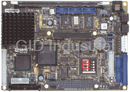
ARCOM 6080-00629-001-103 CPU Board - Fan-less EBX form factor board, based on the 233MHz MMX-enhance...
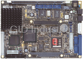
ARCOM 6081-00629-001-103 CPU Board - Fanless EBX form factor board, based on the 233MHz MMX-enhanced...
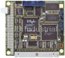
386EX PC/104 Single Board Computer
386EX PC/104 Single Board Computer
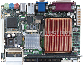
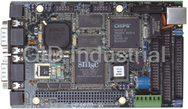
Arcom ELAN-104NC QNX Development Kit | CPU Board with PC/104 Compatible Embedded Processor Card
Request a Quote

The quote request has been received
Close

Facing challenges or have inquiries? Feel free to contact us!
Call Us +1-469-283-2440
What they say about us
FANTASTIC RESOURCE
One of our top priorities is maintaining our business with precision, and we are constantly looking for affiliates that can help us achieve our goal. With the aid of GID Industrial, our obsolete product management has never been more efficient. They have been a great resource to our company, and have quickly become a go-to supplier on our list!
Bucher Emhart Glass
EXCELLENT SERVICE
With our strict fundamentals and high expectations, we were surprised when we came across GID Industrial and their competitive pricing. When we approached them with our issue, they were incredibly confident in being able to provide us with a seamless solution at the best price for us. GID Industrial quickly understood our needs and provided us with excellent service, as well as fully tested product to ensure what we received would be the right fit for our company.
Fuji
HARD TO FIND A BETTER PROVIDER
Our company provides services to aid in the manufacture of technological products, such as semiconductors and flat panel displays, and often searching for distributors of obsolete product we require can waste time and money. Finding GID Industrial proved to be a great asset to our company, with cost effective solutions and superior knowledge on all of their materials, it’d be hard to find a better provider of obsolete or hard to find products.
Applied Materials
CONSISTENTLY DELIVERS QUALITY SOLUTIONS
Over the years, the equipment used in our company becomes discontinued, but they’re still of great use to us and our customers. Once these products are no longer available through the manufacturer, finding a reliable, quick supplier is a necessity, and luckily for us, GID Industrial has provided the most trustworthy, quality solutions to our obsolete component needs.
Nidec Vamco
TERRIFIC RESOURCE
This company has been a terrific help to us (I work for Trican Well Service) in sourcing the Micron Ram Memory we needed for our Siemens computers. Great service! And great pricing! I know when the product is shipping and when it will arrive, all the way through the ordering process.
Trican Well Service
GO TO SOURCE
When I can't find an obsolete part, I first call GID and they'll come up with my parts every time. Great customer service and follow up as well. Scott emails me from time to time to touch base and see if we're having trouble finding something.....which is often with our 25 yr old equipment.
ConAgra Foods