

 Manufacturers
ALLEN-BRADLEY 1785-L26B

Description
Allen-Bradley 1785-L26B Protected PLC-5/20 Controller 16Kb Word SRAM
Part Number
1785-L26B
Price
Request Quote
Manufacturer
ALLEN-BRADLEY
Lead Time
Request Quote
Category
Programmable Controllers
Specifications
Agency Certification(when product is marked)
CSA Class I, Division 2, Groups A, B, C, D, UL listed, CE marked for all applicable directives
Backplane Current
PLC-5/11, -5/20, -5/30 ; 2.3 A, PLC-5/40, -5/40L, -5/60,-5/60L -5/80 ; 3.3 A
Battery
1770-XYC
Communication
DH+ (trunk line: 3,048 cable-m (10,000 cable-ft);drop line: 30.4 cable-m (100 cable-ft), DH using 1785-KA, Serial remote I/O, extended-local I/O (PLC-5/40L and -5/60L processors only)
Environmental Conditions
Operating Temperature. 0 to 60° C (32-140° F), Storage Temperature –40 to 85° C (–40 to 185° F)
Hardware Addressing
2-slot, Any mix of 8-pt modules, 16-pt modules must be I/O pairs, No 32-pt modules 1-slot, Any mix of 8- or 16-pt modules, 32-pt modules must be I/O pairs, 1/2-slot – Any mix of 8-,16-, or 32-pt modules
Heat dissipation
PLC-5/11, -5/20, -5/30 ; 41.30 BTU/hr, PLC-5/40, -5/40L, -5/60,-5/60L -5/80 ; 59.04 BTU/hr
I/O Modules Bulletin
1771 I/O including 8-, 16-, 32-pt, and intelligent modules
Keying
Between 40 and 42, Between 54 and 56
Location
1771-A1B, -A2B, A3B, -A3B1, -A4B, chassis, left-most slot
Maximum I/O
512 (any mix or analog) or 512 in + 512 out (complementary)
Maximum Number of I/O Chassis
Total:13/Extt Local:0/Remote:12
Maximum Number of I/O Racks
4(0-3)
Maximum User Memory Words
16K
Memory modules
1785-ME16 1785-ME64, 1785-ME32 1785-M100
Relative Humidity
5 to 95% (without condensation)
Shock
Operating 30 g peak acceleration for 11±1 ms duration, Non-operating 50 g peak acceleration for 11±1 ms duration
Time-of-Day Clock/Calendar
Maximum Variations at 60° C ± 5 min per month, Typical Variations at 20° C ± 20 s per month, Timing Accuracy:1 program scan
Types of Communication Ports
1 DH+ (Fixed) 1 DH+/Remote I/O (Adapter or Scanner)1 serial port, configurable for RS-232 and 423 and RS-422A compatible
Typical Discrete I/O Scan
0.5 ms / extended-local I/O adapter,10 ms / remote I/O rack at 57.6 kbps ,7 ms / remote I/O rack at 115.2 kbps ,3 ms / remote I/O rack at 230.4 kbps
Vibration(operating and non-operating)
1 g @ 10 to 500 Hz, 0.012 inches peak-to-peak displacement
Features
- 512 through 3072 maximum forcible I/O in any mix
- Advanced instruction set including file handling, sequencer, diagnostic, shift register, immediate I/O, and program control instructions
- Ladder-logic and structured-text programming
- Multiple main control programs for segregation of control tasks
- Processor input interrupts and global status flags
- Programmable fault response for reacting to a fault before the system goes down
- Protected memory selectable by word on selected processors
- Timed interrupt routine for examining specific information at specific time intervals
- Up to 50,176 maximum non-forcible I/O
Datasheet

Extracted Text
Allen-Bradley
Enhanced
Quick Start
PLC-5
Programmable
Controller
(Cat. No. 1785-L11B,
-L20B, -L30B, -L40B,
-L40L, -L60B, -L60L,
-L80B)
Important User Because of the variety of uses for the products described in this
publication, those responsible for the application and use of this
Information
control equipment must satisfy themselves that all necessary steps
have been taken to assure that each application and use meets all
performance and safety requirements, including any applicable laws,
regulations, codes and standards.
The illustrations, charts, sample programs and layout examples
shown in this guide are intended solely for purposes of example.
Since there are many variables and requirements associated with any
particular installation, Allen-Bradley does not assume responsibility
or liability (to include intellectual property liability) for actual use
based upon the examples shown in this publication.
Allen-Bradley publication SGI-1.1, Safety Guidelines for the
Application, Installation, and Maintenance of Solid-State Control
(available from your local Allen-Bradley office), describes some
important differences between solid-state equipment and
electromechanical devices that should be taken into consideration
when applying products such as those described in this publication.
Reproduction of the contents of this copyrighted publication, in
whole or in part, without written permission of Allen-Bradley
Company, Inc., is prohibited.
Throughout this manual we use notes to make you aware of safety
considerations:
ATTENTION: Identifies information about practices
or circumstances that can lead to personal injury or
!
death, property damage or economic loss.
Attention statements help you to:
• identify a hazard
• avoid the hazard
• recognize the consequences
Important: Identifies information that is critical for successful
application and understanding of the product.
PLC, PLC-5/11, -5/20, -5/30, -5/40, -5/40L, -5/60, -5/80, PLC-5, and DH+ are trademarks of Allen-Bradley Company, Inc
Preface
Preface
Read this preface to familiarize yourself with the rest of the manual.
This preface covers the following topics:
• who should use this manual
• the purpose of this manual
• how to use this manual
• conventions used in this manual
• Rockwell Automation support
Who Should Use To use this manual, you should understand programmable controllers
and be able to interpret the ladder logic instructions required to
This Manual
control your application. For more information, see the documents
listed on the following page or contact your local Rockwell
Automation representative.
Purpose of This Manual This manual is for users of the Enhanced PLC-5® processor. It:
• presents you with the basic information you need to get your
system up and running
• provides “memory jogger” information, such as specific bit and
switch settings for modules
• includes high-level procedures with cross-references to other
manuals for more detail
How to Obtain a User Manual There is a user manual associated with this product that contains
detailed information about configuring, programming, and using a
PLC-5 processor. To obtain a copy of the Enhanced and Ethernet
PLC-5 Programmable Controllers User Manual, publication number
1785-6.5.12, you can either:
• view or download an electronic version from the internet:
www.theautomationbookstore.com
• purchase a hardcopy from the internet:
www.theautomationbookstore.com
• contact your local distributor or Rockwell Automation
representative to place an order.
See the table on the next page for other related publications.
Publication 1785-10.4 - November 1998
P-2 Preface
Related Documentation
The following documents contain additional information concerning
the products discussed in this manual.
For more information about: See this document: Publication number:
Enhanced PLC-5 programmable controllers Enhanced and Ethernet PLC-5 Programmable Controllers User Manual 1785-6.5.12
Universal 1771 I/O chassis Universal I/O Chassis Installation Instructions 1771-2.210
power supply Power Supply Modules (1771-P4S, -P6S, -P4S1, -P6S1) 1771-2.135
Installation Instructions
Enhanced and Ethernet PLC-5 Programmable Controllers User Manual 1785-6.5.12
DH+® network
Data Highway/Data Highway Plus/Data Highway II/Data Highway-485 1770-6.2.2
Cable Installation Instructions
communication cards 1784-KTx Communication Interface Card User Manual 1784-6.5.22
Allen-Bradley Publication Index (for your specific communication card) SD499
cables Enhanced and Ethernet PLC-5 Programmable Controllers User Manual 1785-6.5.12
batteries Allen-Bradley Guidelines for Lithium Battery Handling and Disposal AG-5.4
grounding and wiring Allen-Bradley Allen-Bradley Programmable Controller Wiring and Grounding Guidelines 1770-4.1
programmable controllers
current Allen-Bradley documentation, Allen-Bradley Publication Index SD499
including ordering instructions
terms and definitions Allen-Bradley Industrial Automation Glossary AG-7.1
Common Techniques Used in We use the following conventions throughout this manual:
This Manual
• Bulleted lists provide information, not procedural steps.
• Numbered lists provide sequential steps or hierarchical
information.
We use this symbol to indicate additional references you can use
when you need more information about a particular topic.
Publication 1785-10.4 - November 1998
Preface P-3
Rockwell Automation Support Rockwell Automation offers support services worldwide, with over
75 sales/support offices, 512 authorized distributors, and 260
authorized systems integrators located throughout the United States
alone, plus Rockwell Automation representatives in every major
country in the world.
Local Product Support
Contact your local Rockwell Automation representative for:
• sales and order support
• product technical training
• warranty support
• support service agreements
Technical Product Assistance
If you need to contact Rockwell Automation for technical assistance,
call your local Rockwell Automation representative.
Your Questions or Comments about This Manual
If you discover a problem with this manual, please notify us of it
by completing and sending the enclosed Publication Problem Report
(at the back of this manual).
If you have any suggestions about how we can make this manual
more useful to you, please contact us at the address below:
Allen-Bradley Company, Inc.
Automation Group
Technical Communication
1 Allen-Bradley Drive
Mayfield Heights, OH 44124-6118
Telephone: (440) 646-5000
FAX: (440) 646-4320
Publication 1785-10.4 - November 1998
Table of Contents
Overview Chapter 1
What You Need to Do . . . . . . . . . . . . . . . . . . . . . . . . . . . . . . . . . . . . . . 1-1
Identifying the Processor’s Front Panel Components . . . . . . . . . . . . . . 1-2
Components You Need . . . . . . . . . . . . . . . . . . . . . . . . . . . . . . . . . . . . . 1-4
Compliance to European Union Directives . . . . . . . . . . . . . . . . . . . . . . 1-4
EMC Directive. . . . . . . . . . . . . . . . . . . . . . . . . . . . . . . . . . . . . . . . . . 1-4
Low Voltage Directive . . . . . . . . . . . . . . . . . . . . . . . . . . . . . . . . . . . 1-4
Set up the Hardware Chapter 2
Install the Hardware. . . . . . . . . . . . . . . . . . . . . . . . . . . . . . . . . . . . . . . . 2-2
Configure the I/O Chassis . . . . . . . . . . . . . . . . . . . . . . . . . . . . . . . . . 2-2
Ground the I/O Chassis . . . . . . . . . . . . . . . . . . . . . . . . . . . . . . . . . . . 2-4
Install the Power Supply . . . . . . . . . . . . . . . . . . . . . . . . . . . . . . . . . . 2-4
Install the PLC-5 Processor . . . . . . . . . . . . . . . . . . . . . . . . . . . . . . . . 2-5
Power Up the System. . . . . . . . . . . . . . . . . . . . . . . . . . . . . . . . . . . . . 2-6
Install the I/O Modules . . . . . . . . . . . . . . . . . . . . . . . . . . . . . . . . . . . 2-6
Connect the Personal Computer to the PLC-5 Processor . . . . . . . . . . . 2-6
Set up the Software Chapter 3
Install the Software and Set Up the Programming System . . . . . . . . . . 3-1
Start the Programming Software . . . . . . . . . . . . . . . . . . . . . . . . . . . . . . 3-1
Power Up the System. . . . . . . . . . . . . . . . . . . . . . . . . . . . . . . . . . . . . . . 3-2
Troubleshoot the Processor Chapter 4
Use the PLC-5 Processor Status Indicators . . . . . . . . . . . . . . . . . . . . . . 4-1
System
Troubleshoot General Problems . . . . . . . . . . . . . . . . . . . . . . . . . . . . 4-1
Troubleshoot the Processor Communication Channels. . . . . . . . . . . 4-2
Specifications Appendix A
General. . . . . . . . . . . . . . . . . . . . . . . . . . . . . . . . . . . . . . . . . . . . . . . . . A-1
Battery Specification . . . . . . . . . . . . . . . . . . . . . . . . . . . . . . . . . . . . . . A-2
Battery Type . . . . . . . . . . . . . . . . . . . . . . . . . . . . . . . . . . . . . . . . . . A-2
Average Battery Lifetime Specifications. . . . . . . . . . . . . . . . . . . . . A-2
Processor Specifications . . . . . . . . . . . . . . . . . . . . . . . . . . . . . . . . . . . A-3
Publication 1785-10.4 - November 1998
Chapter 1
Overview
This quick start is designed to provide you with the information you
need to get your system up and running quickly. Use this document if
you are knowledgeable about Enhanced PLC-5 products, but may not
have used one or more of them recently. The information we provide
is geared to “jog your memory”.
What You Need to Do If you need more information, see the Enhanced and Ethernet PLC-5
Programmable Controllers User Manual, publication number
1785-6.5.12 (see page P-1 for information about how to obtain a copy
of this manual).
PC with
Programming
Software
Set up the Hardware
(Chapter 2)
Set up the Software
(Chapter 3)
PLC-5/20 Internal
Processor Power Supply
Troubleshoot the
Processor System
(Chapter 4)
Data Highway
Plus
Publication 1785-10.4 - November 1998
1-2 Overview
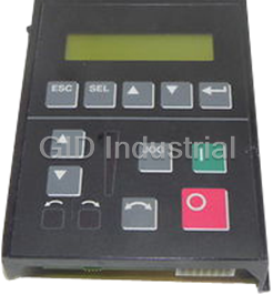
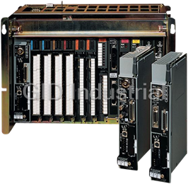
Identifying the Processor’s Front These pictures show the Enhanced PLC-5 processor front panel
components.
Panel Components
PLC-5/11, -5/20, and -5/26 Processor Front Panel
PLC-5/11 Processor
battery indicator (red when
the battery is low)
processor RUN/FAULT
indicator (green when
running; red when faulted)
keyswitch; selects processor mode
force indicator (amber when
I/O forces are enabled)
channel 0 communication
channel 0-25-pin D-shell serial port;
status indicator (green when
supports standard EIA RS-232C and
the channel is communicating)
RS-423 and is RS-422A compatible
Use this port with ASCII or DF1
Install memory module here.
full-duplex, half-duplex master, and
half-duplex slave protocols. The port's
default configuration supports processor
programming:
DF1 point-to-point one stop-bit
2400 bps BCC error check
Install battery here
no parity no handshaking
channel 1A status indicator
(lights green and red)
channel 1B status indicator
8-pin mini-DIN, DH+ programming
(lights green and red)
terminal connection parallel to
channel 1B communication port;
channel 1A
its default configuration is remote
I/O scanner
channel 1A communication port; for
the PLC-5/11 processor, the default
PLC-5 family member designation
configuration is DH+
channel 1A communication port;
this 3-pin port is a dedicated DH+ port
PLC-5/30 Processor Front Panel
battery indicator (lights red when the
battery is low)
processor RUN/FAULT indicator (green
when running; red when faulted)
force indicator (amber when
I/O forces are enabled)
keyswitch; selects processor mode
channel 0 communication status indicator
(green when the channel is communicating)
channel 0-25-pin D-shell serial port; supports standard
EIA RS-232C and RS-423 and is RS-422A compatible
Use this port with ASCII or DF1 full-duplex, half-duplex
master, and half-duplex slave protocols. The port's
default configuration supports processor programming:
DF1 point-to-point one stop-bit
channel 1A status indicator
2400 bps BCC error check
(lights green and red)
no parity no handshaking
channel 1B status indicator (lights green and red)
8-pin mini-DIN, DH+ programming terminal
connection parallel to channel 1A
Install memory module here
channel 1A communication port;
its default configuration is DH+
Use these labels to write information about the
channel: communication mode, station addresses, etc.
channel 1B communication port;
its default configuration is remote I/O scanner
Install battery here
PLC-5 family member designation
Publication 1785-10.4 - November 1998
Overview 1-3
PLC-5/40, -5/46, -5/60, -5/80, and -5/86 Processor Front Panels
battery indicator (red when the battery is low)
processor RUN/FAULT indicator (green when
running; red when faulted)
keyswitch; selects processor mode
force indicator (amber when I/O forces are enabled)
channel 0 communication status indicator
(green when the channel is communicating)
channel 2A status indicator
(lights green and red)
8-pin mini-DIN, DH+ programming
terminal connection parallel to channel
2A when channel 2A is configured for
channel 2B status indicator (lights green and red)
DH+ communications
channel 0-25-pin D-shell serial port; supports standard
EIA RS-232C and RS-423 and is RS-422A compatible
channel 2A communication port;
Use this port with ASCII or DF1 full-duplex, half-duplex
its default configuration is unused
master, and half-duplex slave protocols. The port's
default configuration supports processor programming:
channel 2B communication port;
its default configuration is unused
DF1 point-to-point one stop-bit
2400 bps BCC error check
no parity no handshaking
channel 1A status indicator
(lights green and red)
channel 1B status indicator (lights green and red)
8-pin mini-DIN, DH+ programming terminal
connection parallel to channel 1A
Use these labels to write information about the
channel: communication mode, station addresses etc.
channel 1A communication port;
its default configuration is DH+
Install memory module here
channel 1B communication port;
its default configuration is remote I/O scanner
PLC-5 family member designation
Install battery here
ATTENTION: Make sure you understand the anti-static environment.
The processor is shipped in a static-shielded container to guard against
!
electrostatic damage. Electrostatic discharge can damage integrated
circuits or semiconductors in the processor module if you touch
backplane connector pins. It can also damage the module when you set
configuration plugs or switches inside the module. Avoid electrostatic
damage by observing the following precautions.
• Remain in contact with an approved ground point while handling the
module (by wearing a properly grounded wrist strap).
• Do not touch the backplane connector or connector pins.
• When not in use, keep the module in its static-shielded container.
Wrist strap
Publication 1785-10.4 - November 1998
1-4 Overview
Components You Need
Product name: Catalog number:
Hardware
Enhanced PLC-5 processor 1785-L11B, -L20B, -L30B, -L40B, -L40L, -L60B,
with 2 keys -L60L, -L80B
Lithium Battery 1770-XYC
(in a clear bag)
I/O chassis 1771-A1B, -A2B, -A3B, -A3B1, -A4B
Power supply 1771-P4S, -P6S, -P4S1, -P6S1
Programming System
PC Check your programming software documentation for
system requirements, such as memory, etc.
PLC-5 programming Choose a programming software package that is
software compatible with Enhanced PLC-5 processors.
communication module DH+ interface and interconnect cable
Important: In this manual, we assume you are using a brand-new
Enhanced PLC-5 processor out of the box.
Compliance to If this product has the CE mark it is approved for installation within
the European Union and EEA regions. It has been designed and tested
European Union Directives
to meet the following directives.
EMC Directive
This product is tested to meet Council Directive 89/336/EEC
Electromagnetic Compatibility (EMC) and the following standards,
in whole or in part, documented in a technical construction file:
• EN 50081-2EMC – Generic Emission Standard, Part 2 –
Industrial Environment
• EN 50082-2EMC – Generic Immunity Standard, Part 2 –
Industrial Environment
This product is intended for use in an industrial environment.
Low Voltage Directive
This product is tested to meet Council Directive 73/23/EEC Low
Voltage, by applying the safety requirements of EN 61131-2
Programmable Controllers, Part 2 – Equipment Requirements and
Tests.
For specific information required by EN 61131-2, see the appropriate
sections in this publication, as well as the following Allen-Bradley
publications:
• Industrial Automation Wiring and Grounding Guidelines For
Noise Immunity, publication 1770-4.1
• Guidelines for Handling Lithium Batteries, publication AG-5.4
• Automation Systems Catalog
Publication 1785-10.4 - November 1998
Chapter 2
Set up the Hardware
Install the hardware
Install the hardware
(page 2-2)
PC with
1
(page 2-2)
Programming
Software
Connect the personal computer
Connect the personal computer
to the PLC-5 processor
2
to the PLC-5 processor
(page 2-6)
(page 2-6)
Internal
PLC-5/20
Power Supply
Processor
Data Highway
Plus
For more information, see the Enhanced and Ethernet User Manual,
publication number 1785-6.5.12.
Publication 1785-10.4 - November 1998
12 3 4 5 6 7 8
O
N
O
F
F
2-2 Set up the Hardware
Install the Hardware Configure the I/O Chassis
1 Set the backplane switches.
Pressed in
at top ON (closed)
Pressed in Switch
Last State
at bottom OFF (open)
1
Outputs of this I/O chassis remain in their last state when
on
1 1
a hardware failure occurs.
Outputs of this I/O chassis are turned off when a
off
1
hardware failure occurs.
Always
Switches
Off
Addressing
45
off off 2 - slot
off on 1 - slot
on off 1/2 - slot
on on Not allowed
Switches
EEPROM Transfer
67
2, 3
off off EEPROM memory transfer to processor memory at power-up. ` ´
EEPROM memory transfers to processor memory if processor memory
on on
not valid.
4
EEPROM memory does not transfer to processor memory. ˆ
on off
Switch
Processor Memory Protection
8
Processor memory protection disabled.
off
5
Processor memory protection enabled. ˜
on
1 Regardless of this switch setting, outputs are turned off when any of the following occurs:
- processor detects a runtime error
- an I/O chassis backplane fault occurs
- you select program or test mode
- you set a status file bit to reset a local rack
2` If an EEPROM module is not installed and processor memory is valid, the processor's PROC LED indicator blinks,
and the processor sets S:11/9, bit 9 in the major fault status word. To clear this fault, change the processor from
program mode to run mode and back to program mode.
3
´ If the processor's keyswitch is set in REMote, the processor enters remote RUN after it powers up and has its
memory updated by the EEPROM module.
4
ˆ A processor fault (solid red PROC LED) occurs if processor memory is not valid.
5˜ You cannot clear processor memory when this switch is on.
19309
Publication 1785-10.4 - November 1998
O1 2 34 5 6 78
N
O
F
F
Set up the Hardware 2-3
2
Set the power supply
configuration jumper.
Are you using a power
supply module in
PLC-5/20
3 Install the keying bands.
the chassis?
Processor
YN
2
4
6
8
10
12
14
16
18
Keying
20
22
Bands
24
26
28
30
32
YN
34
36
38
40
42
44
46
48
50
52
54
56
between
- 40 & 42
- 54 & 56
20609-M
Configuring an I/O rack for a local PLC-5 is different than
configuring a remote I/O rack using a 1771-ASB module. For more
information about configuring a remote I/O rack using a 1771-ASB
module, see the following:
• Remote I/O Adapter Module User Manual, publication number,
1771-6.5.83
• Enhanced and Ethernet PLC-5 Programmable Controllers User
Manual, publication number 1785-6.5.12
For more information, see the Universal I/O Chassis installation
instructions, publication number 1771-2.10.
Publication 1785-10.4 - November 1998
2-4 Set up the Hardware
Ground the I/O Chassis
Enclosure
Grounding Electrode
Conductor
Ground
Bus
To Grounding
Electrode System
Ground Lug
Nut and
Captive Washer
Star
Washer
Ground Lug
I/O Chassis Wall
20626-M
For more information, see the Allen-Bradley Programmable
Controller Wiring and Grounding Guidelines, publication number
1770-4.1.
Install the Power Supply
1 Set the jumpers on
the back side of the
power supply like this:
Locking
Bar
2 Connect the power cord to the 120V ac
connector of the power supply module.
This side plugs into connector on the module.
insert wire insert wire
here here
or
place tool here
place tool here
3 Install the power supply in the chassis
20619-M
and snap the module-locking bar over
the modules
Publication 1785-10.4 - November 1998
Set up the Hardware 2-5
For more information, see the Power Supply Modules
(1771-P4S, -P6S, -P4S1, -P6S1) Installation Instructions, publication
number 1771-2.135 or the AC (120/220V) 16A Power Supply
(1771-P7 Series B/C) Installation Instructions, publication number
1771-5.39.
Install the PLC-5 Processor
1Define the DH+ Station Address of Channel 1A
by setting switch assembly SW-1 on the back of
the processor. (See the side of the processor if
you want to use another address.)
Locking Bar
side view of processor
Lift Ejector Tab
PLC-5/20
1 2 3 4 5 67
Processor
Battery Connector
side view
Battery Cover
For series E and later processors:
down
use this switch to select baud rate
57.6 Kbaud
For series D and earlier processors:
+
up
this switch is always off
230 Kbaud
Card Guides
20610-M
2
Specify the digital interface of channel 0.
-
bottom view of PLC-5/11 and -5/20 processor
Battery
Front of
Processor
For detailed information about handling and disposing of the battery
More
as well as other important guidelines, see publication AG-5.4.
12 3 4 5 6 7 8 9 10
For more information, see the Enhanced and Ethernet PLC-5 bottom view of PLC-5/30, -5/40, -5/40L, -5/60,
More
-5/60L and -5/80 processor
Programmable Controllers User Manual, publication number
1785-6.5.12.
Front of
Processor
side view
12345 67 8 910
OFF
3 To install the battery, slide the battery-side
connector into the processor-side connector
until you hear them snap together, and attach
the battery cover.
4 Install the processor module.
Publication 1785-10.4 - November 1998
2-6 Set up the Hardware
Power Up the System
Power up the system. Check the LED display on the processor. If
your system is operating properly, the PROC LED should be steady
red. If the PROC LED is not red, see chapter 4 for troubleshooting
information before you install any I/O modules.
Install the I/O Modules
Locking
Bar
Install each I/O module and connect
the wiring arm.
Card Guides
20618-M
For more information, see the installation instructions or user manual
for the particular module you are installing.
Connect the Personal For more information, see:
Computer to the
• Enhanced and Ethernet PLC-5 Programmable Controllers User
Manual, publication number 1785-6.5.12
PLC-5 Processor
• the documentation provided with your communication card
• Data Highway/Data Highway Plus/Data Highway II/Data
Highway 485 Cable Installation Manual, publication 1770-6.2.2
Publication 1785-10.4 - November 1998
Chapter 3
Set up the Software
Install the software
1
Start the programming software
2
Powerup the system
3
The following instructions are general. For specific information, see
the documentation set for your particular software package.
Install the Software and Set Before you install your programming software, make certain you
meet the system requirements for that software – sufficient disk
Up the Programming System
space, memory, etc. Then, follow the procedures outlined in the
software documentation to install the software and configure
communication.
Start the Start the programming software by following the procedures
described in your programming software documentation.
Programming Software
If you have difficulty, verify that the power supply is turned on.
To monitor your system as you configure and run it, check the
processor LED display for the following indicators:
This LED: lights when:
COMM you establish DH+ communication
BATT no battery is installed or the battery voltage is low
REM I/O you establish Remote I/O communication
ADAPT the processor is in adapter mode
FORCE forces are present in your ladder program
Publication 1785-10.4- November 1998
3-2 Set up the Software
Power Up the System Power up the system if you have not done so already. Check the LED
display on the processor. If your system is operating properly, the
PROC LED should be steady red and the message “Processor RAM
is faulted. Press
Frequently asked questions
How does Industrial Trading differ from its competitors?

Is there a warranty for the 1785-L26B?
Which carrier will Industrial Trading use to ship my parts?
Can I buy parts from Industrial Trading if I am outside the USA?
Which payment methods does Industrial Trading accept?
Why buy from GID?

Quality
We are industry veterans who take pride in our work

Protection
Avoid the dangers of risky trading in the gray market

Access
Our network of suppliers is ready and at your disposal

Savings
Maintain legacy systems to prevent costly downtime

Speed
Time is of the essence, and we are respectful of yours
Related Products
Allen Bradley 1201-HCS2 Programmer/Controller with Digital Speed Control & Upload/Download Capable
Allen-Bradley 1785-L46C15 Protected PLC-5/40C for ControlNet Phase 1.5

Allen-Bradley 1785-L86B Protected PLC-5/80 Controller 100Kb Word SRAM

Allen-Bradley 1785-LTR Modified PLC-5/15 Processor Module 6Kb Memory
Request a Quote

The quote request has been received
Close

Facing challenges or have inquiries? Feel free to contact us!
Call Us +1-469-283-2440
What they say about us
FANTASTIC RESOURCE
One of our top priorities is maintaining our business with precision, and we are constantly looking for affiliates that can help us achieve our goal. With the aid of GID Industrial, our obsolete product management has never been more efficient. They have been a great resource to our company, and have quickly become a go-to supplier on our list!
Bucher Emhart Glass
EXCELLENT SERVICE
With our strict fundamentals and high expectations, we were surprised when we came across GID Industrial and their competitive pricing. When we approached them with our issue, they were incredibly confident in being able to provide us with a seamless solution at the best price for us. GID Industrial quickly understood our needs and provided us with excellent service, as well as fully tested product to ensure what we received would be the right fit for our company.
Fuji
HARD TO FIND A BETTER PROVIDER
Our company provides services to aid in the manufacture of technological products, such as semiconductors and flat panel displays, and often searching for distributors of obsolete product we require can waste time and money. Finding GID Industrial proved to be a great asset to our company, with cost effective solutions and superior knowledge on all of their materials, it’d be hard to find a better provider of obsolete or hard to find products.
Applied Materials
CONSISTENTLY DELIVERS QUALITY SOLUTIONS
Over the years, the equipment used in our company becomes discontinued, but they’re still of great use to us and our customers. Once these products are no longer available through the manufacturer, finding a reliable, quick supplier is a necessity, and luckily for us, GID Industrial has provided the most trustworthy, quality solutions to our obsolete component needs.
Nidec Vamco
TERRIFIC RESOURCE
This company has been a terrific help to us (I work for Trican Well Service) in sourcing the Micron Ram Memory we needed for our Siemens computers. Great service! And great pricing! I know when the product is shipping and when it will arrive, all the way through the ordering process.
Trican Well Service
GO TO SOURCE
When I can't find an obsolete part, I first call GID and they'll come up with my parts every time. Great customer service and follow up as well. Scott emails me from time to time to touch base and see if we're having trouble finding something.....which is often with our 25 yr old equipment.
ConAgra Foods