

 Manufacturers
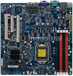
AAEON 9LIF5

Description
Intel Socket 478, Intel 845GE + ICH4, Micro-ATX Motherboard
Part Number
9LIF5
Price
Request Quote
Manufacturer
AAEON
Lead Time
Request Quote
Category
Single Board Computers
Specifications
System Chipset
Intel 845GV
Form Factor
Micro ATX
Ethernet Chipset
VIA VT6105
Datasheet

Extracted Text
9LIF5 Intel Socket 478 Intel 845GE + ICH4 Micro-ATX Motherboard User’s Guide Version 1.0 Federal Communications Commission Statement This device complies with FCC Rules Part 15. Operation is subject to the following two conditions: * This device may not cause harmful interference. * This device must accept any interference received, including interference that may cause undesired operation. This equipment has been tested and found to comply with the limits for a Class B digital device, pursuant to Part 15 of the FCC Rules. These limits are designed to provide reasonable protection against harmful interference in a residential installation. This equipment generates, uses, and can radiate radio frequency energy. If this equipment is not installed and used in accordance with the manufacturer's instructions, it may cause harmful interference to radio communications. However, there is no guarantee that interference will not occur in a particular installation. If this equipment does cause harmful interference to radio or television reception, which can be determined by turning the equipment off and on, the user is encouraged to try to correct the interference by one or more of the following measures: * Reorient or relocate the receiving antenna. * Increase the separation between the equipment and receiver. * Connect the equipment to an outlet on a circuit different from that to which the receiver is connected. * Consult the dealer or an experienced radio/TV technician for help. The use of shielded cables for connection of the monitor to the graphics card is required to assure compliance with FCC regulations. Changes or modifications to this unit not expressly approved by the party responsible for compliance could void the user's authority to operate this equipment. Canadian Department of Communications Statement This digital apparatus does not exceed the Class B limits for audio noise emissions from digital apparatuses set out in the Radio Interference Regulations of the Canadian Department of Communications. Manufacturer's Disclaimer Statement The information in this document is subject to change without notice and does not represent a commitment on the part of the vendor. No warranty or representation, either expressed or implied, is made with respect to the quality, accuracy or fitness for any particular purpose of this document. The manufacturer reserves the right to make changes to the content of this document and/or the products associated with it at any time without obligation to notify any person or organization of such changes. In no event will the manufacturer be liable for direct, indirect, special, incidental or consequential damages arising out of the use or inability to use this product or documentation, even if advised of the possibility of such damages. This document contains materials protected by copyright. All rights are reserved. No part of this manual may be reproduced or transmitted in any form, by any means or for any purpose without expressed written consent of its authors. Product names appearing in this document are mentioned for identification purposes only. All trademarks, product names or brand names appearing in this document are registered property of their respective owners. Printed in Taiwan. TABLE OF CONTENTS Chapter 1 Introduction ................................................................ 1 1-1 Product Specifications........................................................................................ 1 1-2 Package Contents ............................................................................................... 2 1-3 Motherboard Layout ......................................................................................... 3 Chapter 2 Hardware Setup.......................................................... 4 2-1 Installing a CPU Processor for Socket 478 ...................................................... 4 2-2 Setting Your CPU’s Parameters........................................................................ 5 2-3 Main Memory Configuration............................................................................ 7 2-4 Connector and Jumper Settings........................................................................ 8 Chapter 3 BIOS Setup Program................................................ 20 3-1 Standard CMOS Setup .................................................................................... 21 3-2 Advanced BIOS Features................................................................................. 22 3-3 Advanced Chipset Features............................................................................. 25 3-4 Integrated Peripherals ..................................................................................... 27 3-5 Power Management Setup............................................................................... 30 3-6 PNP/PCI Configurations ................................................................................. 33 3-7 PC Health Status .............................................................................................. 34 3-8 Frequency / Voltage Control............................................................................ 35 3-9 Load Fail-Safe Defaults ................................................................................... 36 3-10 Load Optimized Defaults............................................................................... 36 3-11 Supervisor Password & User Password Setting .......................................... 36 3-12 Save and Exit Setup ....................................................................................... 37 3-13 Exit Without Saving ....................................................................................... 37 Chapter 4 DRIVER Setup.......................................................... 38 4-1 Intel Chipset Software Installation Utility…………………………………..38 4-2 Intel Application Accelerator………………………………………………...40 4-3 Video Application……………………………………………………………. 43 4-4 DirectX 9.0 Setup……………………………………………………………. .45 4-5 Audio Driver Setup……………………………………………………………47 4-6 LAN Driver……………………………………………………………………49 4-7 USB 2.0 Driver………………………………………………………………...49 Chapter 1 Chapter 1 Introduction 1-1 Product Specifications Processor - Supports Intel Celeron/Pentium 4 Socket 478 CPU - Supports Intel Celeron/Pentium 4 system bus at 400/533MHz Chipset - Intel 845GV + ICH4 Main Memory - Supports two 184 pin DDR DIMMs up to 2GB - Supports PC1600/2100/2700 DDR SDRAM modules Expansion Slots - Three 32-Bit PCI slots (v2.2 compliant) On-board video subsystem - Integrated 2D/3D graphics accelerator - Full frame DVD audio and video playback - Integrated 24- bit 230 MHz RAMDAC - Shared system memory uses Intel D.V.M. technology Audio Subsystem via AC-Link - With external high quality AC’97 Codec - Complete software driver support for Windows® OS Two UltraDMA-66/100 IDE Ports - Supports PIO Mode 4 up to 16.6MBps, Multi-Word DMA Mode 2 and Ultra DMA mode 5 up to 100MB/s with Bus Mastering - Bus-Mastering software drivers for all common multi-tasking operating systems Embedded USB 2.0 Controller - Three UHCI USB 1.0 Controllers support total 6 USB 1.0 Ports - One EHCI USB 2.0 Controller supports the same 6 ports for USB 2.0 High-Speed Device@ 480 Mb/s Transfer Rates - Optional USB adapter for additional USB 2.0 / 1.1 ports 1 Chapter 1 On-board Super I/O Controller - ITE 8712 LPC I/O with system monitor hardware - Two UARTs support serial port and IR function (up to 115.2Kbps) for HPSIR and ASKIR - One SPP/ECP/EPP parallel port - One floppy disk drive connector supports up to 2.88MB - Integrates smart card reader function and interface, to be qualified for meeting PC/SC standard Embedded System Monitoring - 8 external voltage inputs - 1 temperature sensor for CPU - 2 Fan speed (CPU and system) monitoring with on/off control in suspend Fast Ethernet Controller - Onboard VIA VT6105 LOM supports 10/100Mb Fast Ethernet Boot-Block Flash ROM - Award system BIOS supports PnP, APM, DMI, ACPI, & Multi-device booting features. 1-2 Package Contents This product comes with the following components: 1. Motherboard x 1 2. 40-Pin UDMA-100 IDE Cable x 1 Blue to motherboard, Gray to Master and Black to Slave 3. 34-Pin floppy Disk Drive Cable x 1 4. User’s Guide x 1 5. Driver CD x 1 2 Chapter 1 1-3 Motherboard Layout 3 Chapter 2 Chapter 2 Hardware Setup If your motherboard has already been installed in your computer you may still need to refer to this chapter if you plan to upgrade your system's hardware. This motherboard is electrostatic sensitive. Do not touch without wearing proper safety item and make sure to disconnect the power cable from the power source before performing any work on your motherboard. Not doing so may result in electrical shock! 2-1 Installing a CPU Processor for Socket 478 The Intel® Socket 478, designed for the Pentium 4 processor, has been incorporated as a standard motherboard specification. To insert your CPU into the Socket 478 please follow the steps below: 1. Locate the 478-pin CPU socket on the motherboard. 2. Unlock the socket by pressing the lever sideways, and then open it up to a 90-degree angle. 3. Locate a Gold Mark on the top surface of the CPU, which is close to one of the CPU corners. The same corner may also be cut off, leaving a noticeable notch in the CPU's corner. These markings indicate Pin 1 on the CPU. 4. Gently insert the CPU with Gold Mark/Pin 1 at the same corner of Socket 478, which is located close to the end of the lever. Allow the weight of the CPU to push itself into place. Do not apply extra pressure as doing so may result in damage to your CPU. 5. When the CPU is correctly inserted, close the lever with your finger on top of the CPU to make sure the CPU is properly embedded into the socket. 6. Insert an appropriate heat sink and fan for proper heat dissipation. Installing a standard Intel® specified heat sink with cooling fan is necessary for proper heat dissipation from your CPU. Failing to install these items may result in overheating and possible damage to your CPU. In order to boot up with a newly installed CPU, AC Power must be switched off before installation. 4 Chapter 2 2-2 Setting Your CPU’s Parameters “Hyper-Threading Technology” Basic requirements for Hyper-Threading Technology: - CPU: An Intel® Pentium® 4 Processor with HT Technology; - Chipset: An Intel® Chipset that supports HT Technology; - BIOS: A BIOS that supports HT Technology and has it enabled; and - OS: An operating system that supports HT Technology. Boxed Processor FSB Chipset Support � 800 MHz FSB processors require a new chipset � Willamette (0.18) processors are not supported on 875/865 chipsets Processor FSB HTT Supporting Non-Supporting Chipsets Chipsets Intel Pentium 4 Processor 800 MHz Yes 875P, 865G/PE 865P, 850E, 845(all) Intel Pentium 4 Processor 533 MHz Yes 865G/PE/P, 850E, 845GL (3.06GHz) 845(all) Intel Pentium 4 Processor 533 MHz& 400 No 865G/PE/P, 850E, N/A (1.6AGHz, 1.8AGHz, MHz 845(all) 2.0AGHz and above) Intel Celeron Processor (2.0GHz and above) Intel Pentium 4 Processor 400 MHz No 850E, 845(all) 865 (all), 875P (2.0GHz, 1.8 GHz, 1.6GHz and below) Intel Celeron Processor (1.8GHz and below) 5 Chapter 2 Frequency Configuration: This motherboard uses a new user-friendly technology that enables the user to setup a main board’s CPU parameters through an easy to use BIOS setup procedure. It is no longer necessary to make many jumper settings as on conventional motherboard. After installing all your hardware into your PC system, you can manually configure your CPU clock ratio and CPU clock according to your processor’s specifications. After turning on your system’s power, enable the CMOS Setup Utility by pressing the delete key when your BIOS identification screen appears, then go to the Frequency/ Voltage control option and select your CPU clock ratio and CPU clock speed (please refer to Chapter3 for more details). How to Derive your CPU Core Speed? � CPU Core Speed = CPU Clock * Core/Bus Ratio You do not need to change any voltage settings because this board will automatically set your CPU voltage. Any attempt to operate beyond product specifications is not recommended. We are not responsible for damages caused by inadequate operation or settings beyond product specifications. 6 Chapter 2 2-3 Main Memory Configuration The DDR SDRAM memory system consists of two banks and can support the memory size up to 1 GB per DIMM. If you only use one bank, it does not matter which one you use and if you use two or more banks, it does not matter which bank you install first. To install your DDR Modules please follow these steps: 1. Unlock a DIMM socket by pressing the retaining clips outward. The DDR Modules has only one notch at the center of module. The DDR module will only fit in the right position. 2. Insert the DDR Module vertically into the DIMM slot, with the correct alignment. Then push it in until the golden finger on the memory module is deeply inserted into the socket. 3. The plastic clip on each side of the DIMM slot will automatically close to hold the DDR Modules in place. 7 Chapter 2 2-4 Connector and Jumper Settings Connectors are used to link the system board with other parts of the system, including the power supply, the keyboard, and the various controllers on the front-panel of the system case. The power supply connector is the last connection to be made while installing a motherboard. Before connecting the power supply, please make sure it is not connected to the power source. PW1 / 2 (ATX Power Supply Connector) The power cord leading from the system's power supply to the external power source must be the very last part connected when assembling a system. The ATX power supply provides a single 20-pin connector interface, which incorporates standard +/-5V, +/-12V, optional 3.3V and Soft-power signals. The Soft power signal, a 5V trickle supply is continuously supplied when AC power is available. When the system is in the Soft-Off mode, this trickle supply maintains the system in its minimum power state. The ATX 12V power supply has a new +12V (4-pin) and +5V/3.3V (6-pin) auxiliary power connector to enable the delivery of more +12 VDC and +5/3.3V VDC current to the motherboard. Power-On By Modem While in Soft-Off state, if an external modem ring-up signal occurs, the system activates and can be remotely accessed. You may enable this function in the BIOS's Power Management Setup menu. (See section 3. 5) 8 Chapter 2 Blinking LED in Suspend Mode While in Suspend mode, the LED light on the front panel of your computer will flash. Suspend mode is entered by pressing the Override Power Button, pushing the Green button on your ATX case, or enabling the Power Management and Suspend Mode options in BIOS's Power Management menu. (See section 3.5) Poly-fuse Over Current Protection The poly-fuse protects the system from dangerous voltages that the system might be exposed to via the keyboard or USB connector. In case of such exposure, the poly-fuse will immediately be disconnected from the circuit, just like a normal fuse. After being disconnected for a certain period of time, the poly-fuse will return to its normal state. Then the keyboard or USB connector can function properly again. Unlike conventional fuses, the poly-fuse does not have to be replaced, relieving the user from such inconveniences. CN1A (Front Panel Connector) 1. PWR-SW (Over-ride Power Button Connector) The power button on the ATX chassis can be used as a normal power switch as well as a device to activate Advanced Power Management Suspend mode. This is a power-saving mode used for saving electricity when the computer is idle for long periods of time. The Soft-OFF by PWR-BTTN function in BIOS's Power Management Setup menu must be set to [Delay 4 Sec.] to activate this function. When the Soft-OFF by PWR-BTTN function is enabled, pushing the power button rapidly will switch the system to Suspend mode. Any occurrence of external activities such as pressing a key on the keyboard or moving the mouse will bring the system back to Full-On. Pushing the button while in Full-On mode for more than [4 seconds] will switch the system completely off. See Over-ride Power Button Operation diagram. 9 Chapter 2 2. P-LED (Power LED Connector) The power indicator LED shows the system's power status. It is important to pay attention to the correct cable and pin orientation (i.e. be careful not to reverse the order of these two connectors.) 3. G-BTN/G-LED (Green Button Switch/LED Connector) Some ATX cases provide a Green button switch, which is used to put the system in Suspend mode. While in Suspend mode, the power supply to the system is reduced to a trickle, the CPU clock is stopped, and the CPU core is in its minimum power state. The system is activated whenever the keyboard or mouse is touched. The system resumes in different ways as defined by Power Management Setup screen in BIOS. 4. RESET (System Reset Switch Connector) This connector should be connected to the reset switch on the front panel of the system case. The reset switch allows you to restart the system without turning the power off. 5. SPEAKER (Speaker Connector) This 4-pin connector connects to the case-mounted speakers. 6. HD-LED (IDE Activity LED Connector) The IDE activity LED lights up whenever the system reads/writes to the IDE devices. FD1 (Floppy Connector) The motherboard provides a standard floppy disk drive connector that supports 360K, 720K, 1.2M, 1.44M and 2.88M floppy disk types. Use this connector to connect to a floppy disk drive of 34 pins. 10 Chapter 2 IDE1 / 2 (IDE Hard-Disk Connector) The motherboard has a 32-bit Enhanced PCI IDE and Ultra ATA66/100 controller that provides PIO mode 0~4, Bus Master, and Ultra ATA66/100 function. This connector is used for connecting 40 pin ATAPI devices. IDE 1 only connects two IDE devices. (Primary Master/Slave) IDE 2 only connects two IDE devices. (Secondary Master/Slave) JP1 (CMOS Clear Jumper) Pin Definition 1-2 Normal (default) 2-3 Clear CMOS Data There is a CMOS RAM on board that has a power supply from external battery to keep the data and system configuration. To clear the contents of the CMOS, please follow the steps below. 1. Disconnect the system power supply from the power source. 2. Set the jumper cap at location [2-3] for <5 seconds>, and then set it back to the default position. 11 Chapter 2 3. Connect the system's power and then start the system. 4. Enter BIOS's CMOS Setup Utility and choose Load Optimized Defaults. Type [Y] and then press [Enter] to continue. 5. Set the system configuration in the Standard CMOS Setup menu. JP6 / 6A (Enable/Disable USB 0/1, 2/3 Device Wake-Up Jumper) Pin Definition 1-2 Disable (default) 2-3 Enable JP6 � USB 0/1 JP6A � USB 2/3 An USB keyboard hot key or an USB mouse click can activate this board. To use this function, select a hot key of your choice at the USB Resume from S3 option under Wake Up Events in the BIOS's Power On Management screen. You must also set this jumper's cap to pins 2-3 to use this function. CN17 (Blue LED Mode Jumper) These features work entirely the same as the power indicator LED, both shows the system’s power status. The only difference is that this one is blue while the other is red LED. 12 SENSE Chapter 2 FAN1 / 2 (CPU/System Cooling Fan Connectors) Connect the CPU/system/case-cooling fan to FAN1/2. The wiring and plugging may vary depending on the manufacturer. On standard fans, the yellow wire is positive (+12V), green is SENSE, and the black wire is ground. CN2 / 2A (CD-ROM Audio-in Connector) Use the audio cable enclosed with your CD-ROM disk drive to connect the CD-ROM to your motherboard. This will enable your CD-ROM's audio function. 13 Chapter 2 CN5 [WOL (Wake-on-LAN) Connector] Enable the Wake Up On LAN selection in BIOS's Power Management Menu to use this function. The capability to remotely manage PCs on a network is a significant factor in reducing administrative and ownership costs. Magic Packet technology is designed to give WOL capability to LAN controller. This header is used to connect an add-in NIC (Network Interface Card) that gives WOL capability to the motherboard. CN5A [WOM (Wake-on-Modem) Connector] Enable the Wake Up On Modem selection in BIOS's Power Management Menu to use this function. This header is used to connect an add-in modem card, which gives WOM capability to the motherboard. 14 Chapter 2 CN23/CN23A (USB 2/3 and 4/5 Connectors): If you want to use an USB Keyboard, you must enable the USB keyboard support function in BIOS's Integrated Peripherals menu (See Section 3.4). This board contains an USB Host controller and a root hub with two connectors is included for an optional USB Adaptor (USB 2/3 and 4/5). CN24 (Front Audio Connector) This connector gives you the option of a front-panel audio-jack cable ext. to be plugged into a special custom-designed system case. Simply remove the two jumper caps at pin [5-6] and [9-10] then plug it into the (optional) cable ext. connector. Pins [5-6] and [9-10] are shorted (default) to enable the back-panel audio function. 15 Chapter 2 IR1 (IR Connector) Select a COM2 Mode in BIOS's Integrated Peripherals menu the COM2 port to support IR function. (See section 3.4 Super I/O Device of Integrated Peripherals) JP5 (Power On by Keyboard) Pin Definition 1-2 Disable (default) 2-3 Enable The PS/2 keyboard (hot key) can turn on the board. To use this function, select a hot key of your choice from BIOS’s Power On Management screen ->Wake Up Events -> PS2 KB Wakeup option. You must also set this jumper’s cap to pins 2-3 to use this function. 16 Chapter 2 CN3 (Auxiliary Audio-in Connector) This connector is for the use of Auxiliary Audio-in Device. CN7 (Smart Card Reader Connector): This connector must be connected to an optional Smart card reader. 17 Chapter 2 JP11 (On-Board LAN) This function allows you to enable or disable the on-board LAN. You must set the jumper cap to pins 1-2 to enable or pins2-3 to disable this function. COM 2 (Serial port / COM Headers) This 9-pin connector is used for connecting a serial-port ribbon cable to an additional COM port. 18 Chapter 2 JP23 (Green LED Mode Jumper) This cap is to setup Green LED flash mode. (Optional) 19 Chapter 3 Chapter 3 BIOS Setup Program Phoenix-Award BIOS ROM has a built-in setup program that allows users to modify the basic system configuration. This information is stored in CMOS RAM so that it can retain the setup information, even when the power is turned off. To enter the Phoenix-Award BIOS setup program press [Delete] when you Power on or reboot the computer system. The primary screen as shown in Figure 3-1 is a list of the menus and functions available in the setup program. Select the desired item by your arrow keys and press enter to make the changes. Operating commands are located at the bottom of this and all other BIOS screens. When a field is highlighted, on-line help information is displayed on the right side of the screen. Figure 3-1 20 Chapter 3 3-1 Standard CMOS Setup The Standard CMOS Setup allows users to configure system components such as hard disk drive, floppy disk drive and video display as well as date, time and boot-up error signaling. This configuration menu should be changed when installing a motherboard for the first time, changing hardware in your system such as the HDD, FDD, video display, or when the CMOS data has been lost or contaminated. Choose the Standard CMOS Setup option from the CMOS Setup Utility menu (Figure 3-1) to display the following screen. Figure 3-2 Date/Time Set the date and time of the system. Do not skip this function as all of your timed events such as power management, saving files, etc are based on this timer. IDE (Primary/Secondary; Master/Slave) This category identifies up to four IDE hard disk drives that have been installed in the computer. This section does not show information on other IDE devices such as CD-ROM drives or other hard drive type such as SCSI drives. Drive A/B Select different Floppy device Model. Available options are [None], [360K, 5-1/4 in], [1.2M, 5-1/4 in], [720k, 3-1/2 in], [1.44M, 3-1/2 in], and [2.88M, 3-1/2 in]. Video Select the type of video adapter present in your system. You can ignore this setting if you are using a VGA monitor; VGA BIOS will automatically configure this setting. 21 Chapter 3 Halt On When the system is powered on, BIOS performs a series of diagnostic tests called POST (Power On Self Test). This function stops the computer if BIOS detects a hardware error. You can tell BIOS to halt on all errors, no errors, or not to halt on specific errors. 3-2 Advanced BIOS Features By choosing the Advanced BIOS Features option from the CMOS Setup Utility menu (Figure 3-1), the screen below is displayed. This sample screen contains the manufacturer's default values for the motherboard. Figure 3-3 Virus Warning When you set as enabled, you receive a warning message if a program (specifically, a virus) attempts to write to the boot sector or the partition table of the hard disk drive. Many disk diagnostic programs that access the boot sector table can trigger the virus-warning message. If you plan to run such a program, we recommend that you first disable the virus warning. CPU L1 & L2 Cache Cache memory is much faster than conventional DRAM system memory. These fields allow you to enable or disable the CPUs Level 1 built-in cache and Level 2 external cache. Both settings are left enabled to significantly increase the performance of your computer. 22 Chapter 3 Hyper –Threading Technology Available options are [Enabled] and [Disabled]. Select [Enable] to support Hyper-Threading Technology and vice versa. Quick Power On Self Test (POST) Enable this function to reduce the amount of time required to run the POST (Power On Self Test). BIOS will save time by skipping some items during POST. It is recommended that you disable this setting. Discovering a problem during boot up is better than loosing data during your work. First/Second/Third/Boot Other Device This option sets the sequence of drives BIOS attempts to boot from after POST completes. BIOS will search these drives for an operating system. Swap Floppy Drive Enabling this function will swap the floppy drive assignment so that drive A will function as drive B, and drive B will function as drive A. Note that the boot sequence assignment mentioned directly above does not include booting from floppy drive B. This function is useful if floppy drives B and A are of a different format and you want to boot from floppy drive B. Boot up Floppy Seek This is a set up check for floppy power-on after starting the computer system. Boot Up NumLock Status This function defines the keyboard's number pad as number keys or arrow keys. If it is set at on the number keys will be activated, if it is set at off the arrow keys will be activated. Gate A20 Option: This allows you to set the Gate A20 status. When set to [Fast], Gate A20 is controlled by chipset. When set to [Normal], Gate A20 is controlled by a specific pin from the keyboard controller. Available options are [Fast] and [Normal]. Keyboard Interface 1. Typematic Rate Setting When enabled, you can set the following two typematic control items. When disabled, the keyboard controller determines keystrokes arbitrarily in your system. 2. Typematic Rate (Chars/Sec) The typematic rate sets the rate at which characters on the screen repeat when a key is pressed and held down. 23 Chapter 3 3. Typematic Delay (Msec) The typematic delay sets how long after you press a key that a character begins repeating. Security Option The Supervisor and/or User Password functions shown in Figure 3-1 must be set to take advantage of this function. See Section 3.11 for password setting information. When the Security Option is set to System, a password must be entered to boot the system or enter the BIOS setup program. When the Security Option is set to Setup, a password is required to enter the BIOS setup program. APIC Mode This item can enable or disable the APIC (Advanced Programmable Interrupt Controller). Due to compliance to PC2001 design guide, the system is able to run in APIC mode. Enabling APIC mode will expand available IRQs resources for the system. Available options are [Enabled] and [Disabled]. MPS Version Control For OS This item allows you to select which MPS (Multi-Processor Specification) version to be used for the operating system. You need to select the MPS version that is supported by your operating system. To find out which version to use, consult the vendor of your operating system. Available options are [1.4] and [1.1]. OS Select (For DRAM >64MB) If your system's DRAM is larger than 64MB and you are running OS/2, select OS/2 as the item value. Otherwise, set the item value to Non-OS/2 for all other operating systems. Small Logo (EPA) Show This setup allows photo that is EPA. Logo. Show POST CODE Enabling this function can show POST error code on the screen before proceeding to operating system. 24 Chapter 3 3-3 Advanced Chipset Features By choosing the [Advanced Chipset Features] option from the CMOS Setup Utility menu (Figure 3-1), the screen below is displayed. This sample screen contains the manufacturer's default values for the motherboard. Figure 3-4 All of the above settings have been determined by the motherboard manufacturer and should not be changed unless you are absolutely sure of what you are doing. Explanation of the DRAM timing and chipset features setup is lengthy, highly technical and beyond the scope of this manual. Below are some abbreviated descriptions of the functions in this setup menu. DRAM Timing Selectable The function allows you to enable or disable the DRAM timing by SPD. It is recommended to keep the default setting for a stable system operation. CAS Latency Time This item controls the latency between DRAM read command and the time the data actually becomes available. Active to Precharge Delay This item controls the number of DRAM clocks used for DRAM parameters. DRAM RAS# to CAS# Delay This item controls the latency between DRAM active command and read/write command. 25 Chapter 3 DRAM RAS# Precharge This item controls the idle clocks after issuing precharge command to the DRAM. System BIOS Cacheable Enabling this function allows caching of the system BIOS ROM at F0000h-FFFFFh, resulting in better system performance. However, if any program writes to this memory area, a system error may result. It is advised to leave this setting. Caching the system BIOS results in better performance than shadowing the system BIOS. Video BIOS Cacheable Enabling this function will allows caching of the video RAM, resulting in better system performance. However, if any programs write to this memory area, a system error may occur. Memory Hole at 15M-16M Enabling this function will reserve the memory address space between 15MB and 16MB for ISA expansion cards. However, it will also result in not allowing the system to have access to memory above 16MB. Please note that some expansion cards require this setting to be enabled. The default setting is Disabled. If Auto Configuration is enabled, you must set the DRAM timing function to 60ns or 70ns, depending on the type of DRAM you install. Delayed Transaction Available options: [Disabled] and [Enabled]. Delay Prior to Thermal Available options: None, 4, 8, 16, and 32 min. AGP Aperture Size This function determines the amount of system memory that is given to the AGP card. Options range from 4MB to 256MB. This is a dynamic memory allotment in that the AGP card will only use the amount of memory that it needs. The remaining memory, which is not in use, will be available for the system. For example, if 16MB is allotted to the AGP card and the card only needs 8MB, the remaining 8MB will be available for system use. On-Chip VGA This enables / disables the onboard VGA functions. By default it is set to [Enabled]. On-Chip Frame Buffer Size The onboard VGA will share system’s memory buffer. You may adjust the size of the shared buffer size. Available options: [1MB], [8MB] 26 Chapter 3 Flash BIOS Protection The motherboard manufacturer developed BIOS protection technology that protects the System BIOS from accidental corruption by unauthorized users or computer viruses. When enabled, the BIOS data cannot be changed when attempting to update BIOS with the FLASH utility. When disabled, the BIOS data can be updated by using the FLASH utility. 3-4 Integrated Peripherals This section provides information on setting peripheral devices. By choosing the Integrated Peripherals option from the CMOS Setup Utility menu (Figure 3-1), the screen below is displayed. This sample screen contains the manufacturer's default values for the motherboard. Figure 3-5 OnChip IDE Device Press [Enter] to enter the sub-menu, which contains the following items for advanced control: 1. On-Chip Primary/Secondary PCI IDE You can set this to disable the On Chip IDE controller if you are going to add a higher performance IDE board 2. IDE Primary/Secondary Master/Slave PIO The four IDE PIO (programmed Input/Output) fields let you set a PIO mode (0-4) for each IDE device that the internal PCI IDE interface supports. Modes 0 through 4 27 Chapter 3 provide successively increased performance. In Auto mode, the system automatically determines the best mode for each device. 3. IDE Primary/Secondary Master/Slave UDMA Ultra DMA implementation is possible only if your IDE device supports it and your operating environment contains a DMA driver. If both your hard drive and software support Ultra DMA, select [Auto] to enable BIOS support. 4. IDE HDD Block Mode Block mode is also called block transfer, multiple commands, or multiple sector read/write. If your IDE hard drive supports block mode, select Enabled to auto-detect the optimal number of block read/writes per sector the drive can support. OnChip PCI Device This section provides information for setting onboard device. By choosing the Integrated Peripherals option from the CMOS Setup Utility menu (Figure 3-5), the screen below is displayed. This sample screen contains the manufacturer's default values for the motherboard Press [Enter] to enter the sub-menu, which contains the following items for advanced control: 1. AC97 Audio This feature allows you to enable/disable the on-board AC97 audio function. 2. AC97 Modem This item allows you to enable/disable the MCP chipset’s feature to support MC97 Modem. Super IO Device This section provides information on setting Super I/O device. By choosing the Integrated Peripherals option from the CMOS Setup Utility menu (Figure 3-5), the screen below is displayed. This sample screen contains the manufacturer's default values for the motherboard. Press [Enter] to enter the sub-menu, which contains the following items for advanced control: 1. Onboard FDC Controller Select Enabled if your system has a floppy disk controller (FDC) installed on the system board and you wish to use it. If you install an add-in FDC or the system has no floppy drive, select Disabled in this field. 2. Onboard Serial Port 1/2 Select an address and corresponding interrupt for the first and second serial ports. Available options are [3F8/IRQ4], [2E8/IRQ3], [3E8/IRQ4], [2F8/IRQ3], [Disabled], and [Auto]. 28 Chapter 3 3. UART Mode Select This function allows you to select an operating mode for the second serial port. (Normal RS-232C serial port / IRDA / SCR / ASKIR 0.57-MB/sec infrared port) 4. UR2 Duplex Mode Available options: [Half] and [Full]. 5. Onboard Parallel Port Select a logical LPT port address and corresponding interrupt for the physical parallel port. 6. Parallel Port Mode Select an operating mode for the onboard parallel (printer) port. Select SPP unless you are certain your hardware and software support one of the other available modes. 7. ECP Mode Use DMA This item automatically specifies a DMA channel 1 or 3 for the parallel port when it is set to [EPP] or [ECP+EPP] mode. 8. Game Port Address This item disables or assigns the address of the Game port. Available options are [Disable], [201] and [209]. 9. Midi Port Address This item disables or assigns the address of the Midi port. Available options are [Disable], [300] and [330]. 10. Midi Port IRQ This item specifies an IRQ for the Midi port. Available options are [5] and [10]. USB Controller/USB 2.0 Controller Enable the on-board Universal Serial Bus (USB V1.1) controller if you want to connect an USB device to your system. Note that if this setting is disabled, you can still temporarily use a USB keyboard during boot up so that you can enter BIOS and enable this setting. If you pass the boot up stage without enabling this function, your PS/2 keyboard will no longer work. USB Keyboard Support Select Enabled if your system has a USB keyboard installed on the system board. If your system has no USB keyboard, select Disabled in this field. Init Display First This function allows users to choose AGP or PCI slot to initialize display. 29 Chapter 3 3-5 Power Management Setup This section provides information on the Green PC power management functions. By choosing the Power Management Setup option from the CMOS Setup Utility menu (Figure 3-1), the screen below is displayed. This sample screen contains the manufacturer's default values for the motherboard. Figure 3-6 ACPI Suspend Type This feature allows user to select a suspend type for the operating system to turn off peripherals devices, such as CD-ROM players, when they are not in use. Run VGABIOS if S3 Resume Available options: [Auto], [Yes] and [No]. Power Management Power management allows the computer to save electricity when it is not in use by entering increasingly deep power saving modes. Video Off Method This function serves as both a screen saver and power saver for monitors. See the next function, Video Off After, for setting the video timer. 1. Blank - BIOS will only blank the monitor's screen. The electricity saved in this mode is negligible and this function is only used as a screen saver to prevent screen damage while the screen is on but not in use. 30 Chapter 3 2. V/H SYNC+Blank - The system turns off the vertical and horizontal synchronization ports, writes blanks to the VGA buffer and the monitor's electron gun turns off. This function requires a monitor with Green features in order to take advantage of the power saving function. If you enable this function and do not have a Green monitor, the result will be the same as if you had selected Blank. This function serves as both a screen saver and a power saver. 3. DPMS Supported - Select this option if your video card supports the Display Power Management Signaling (DPMS) standard (i.e., you have a monitor that supports Green features). Use software supplied by your video subsystem to set video power management options. Video off In Suspend This setting determines when the monitor enters power saving mode if it is set to Yes. The Power Management function must be enabled to use this function. Suspend Type Available options: [Stop Grant] and [Pwr-On Suspend]. MODEM Use IRQ If your computer has a modem use this function to tell BIOS which IRQ is being occupied by the modem card. When the system is in Green mode, the modem requires an IRQ assignment to wake up the system and perform tasks. This assignment is compliant with the APM 1.2 compliant operating systems. Suspend Mode The Power Management function must not be set to disabled to enable this function. If the system runs in Standby mode and the Suspend timer expires, all devices regulated by power management will shut off and the CPU speed will be 0 MHz. HDD Power Down Shuts down any IDE hard disk drives in the system after a period of inactivity as set in this user configurable field. This feature does not affect SCSI hard drives. Soft-Off by PWR-BTTN When set to Delay 4 Sec., this function allows the power button to put the system in Suspend, a power saving mode. When set to Instant-Off the Soft-Off by PWR-BTN function is disabled and the computer turns completely off when the power button is pressed. Primary/Secondary IDE 0/1 Available options: [Disabled] and [Enabled]. FDD, COM, LPT Port Available options: [Disabled] and [Enabled]. 31 Chapter 3 PCI PIRQ [A-D]# Available options: [Disabled] and [Enabled]. Wake up Events 1. Power On By PCI / Onbd LAN When enabled, a PCI interface that receives a signal will wake up the system from soft off and green mode. 2. Power On by Modem When enabled, a Modem will be able to receive a signal and wake up the system from soft off and green mode. You should connect the modem to the COM port and call your PC to power on. 3. Wake Up on LAN (WOL) When enabled, a LAN that receives a signal will wake up the system from soft off and green mode. 4. USB KB Wake-Up From S3 Allows the activity of USB device to wake up the system from S3 power saving modes. Settings are [Enabled] and [Disabled]. 5. Power On by Alarm When enabled, this setting allows the system to turn back on at a designated time of the month. User must designate date of month and time of day. This function is only available when using an ATX power supply and the Software Power-Off function to turn off the computer. 6. POWER ON Function This controls whether the PS/2 mouse or keyboard can power on the system. Available settings are [Password], [Hot KEY], [Mouse Move], [Mouse Click], [BUTTON ONLY] and [Keyboard 98]. 7. KB Power ON Password Sets keyboard power on password to protect the system. 8. Hot Key Power On Available options: [Ctrl-F1] through [Ctrl-F12]. 32 Chapter 3 3-6 PNP/PCI Configurations This section provides IRQ and DMA setting information. By choosing the PNP/PCI Configuration option from the CMOS Setup Utility menu (Figure 3-1), the screen below is displayed. This screen contains the manufacturer's default values for the motherboard. Figure 3-7 Reset Configuration Data If you want to reset CMOS IRQ divide hardware device, please selected to [Enabled]. Resources Controlled By When set to Manual the system BIOS will not refer to the ESCD for IRQ & DMA information. Instead, it will refer to the items in the setup menu for assigning IRQ & DMA. When set to Auto the system BIOS will refer to the ESCD for all legacy information. ESCD (Extended System Configuration Data) provides a detailed format of the configuration data structures stored in flash memory. Each data structure defines the resources used by a device or a card in the system. This includes legacy and PCI/ISA PnP devices. PCI/VGA Palette Snoop When set to [Enabled], multiple VGA devices operating on different buses can handle data from the CPU on each set of palette registers on every video device. Bit 5 of the command register in the PCI device configuration space is the VGA Palette Snoop bit (0 is disabled). Available options are [Enabled] and [Disabled]. FDD IRQ Can Be Free This function allows user to choose if the FDD IRQ can be freed up. The default setting is [Yes] and this does not allow the IRQ to be free. 33 Chapter 3 3-7 PC Health Status By choosing the PC Health Status option from the CMOS Setup Utility menu (Figure 3-1), the screen below is displayed. This field shows you the current system temperature/external voltages input and the current CPU FAN and System FAN operating speed. Figure 3-8 Shutdown Temperature: This item allows you to set the shutdown temperature level for the processor. When the processor reaches the temperature you set, the system will shutdown. This function only works in ACPI-aware OS (such as Windows 98 / ME / 2000). Available options are [70°C/158°F], [65°C/149°F] and [60°C/140°F] 34 Chapter 3 3-8 Frequency / Voltage Control By choosing the Frequency/Voltage Control option from the CMOS Setup Utility menu (Figure 3-1), the screen below is displayed. This sample screen contains the manufacturer's default values for the motherboard. Figure 3-9 Memory Frequency For Please leave the default setting [Auto] for a stable system operation. Auto Detect PCI Clk Enabling this function will auto-detect PCI/DIMM clock. Spread Spectrum Available options are: [Disabled], [+/- 0.25%], [+/- 0.35%], [+/-0.45%], [-0.5%]. Any attempt to operate beyond product specifications is not recommended. We do not guarantee the damages or risks caused by inadequate operation or beyond product specifications. 35 Chapter 3 3-9 Load Fail-Safe Defaults Load Fail-Safe Defaults loads the default BIOS values directly from the CMOS Setup Utility menu (Figure3-1). These settings should be used to bring the system back to a functional level if the system does not respond to the Optimized Defaults. 3-10 Load Optimized Defaults Load Optimized Defaults loads the default system values directly from the CMOS Setup Utility menu (Figure3-1). If the stored record created by the setup program becomes corrupted and therefore unusable, these defaults will be loaded automatically when you turn on the computer. 3-11 Supervisor Password & User Password Setting There are four different variables that control password settings. The first two are located under the Security Option function in BIOS Features Setup Menu (Figure 3-1). When the Security Option function is set to Setup, a password is required to enter BIOS and change BIOS settings. When the Security Option function is set to System, a password is required to enter both BIOS and the computer's operating system (for example Windows 98) found on the boot drive. The third and fourth variables are user password and supervisor password selected in BIOS (Figure 3-1). The main purpose of separating user and supervisor is to allow only the supervisor to have control over the settings in BIOS. The user, on the other hand, is only allowed to access the computer's operating system and change the user password in BIOS. When there is no supervisor password set, the user password controls access to all BIOS settings. 36 Chapter 3 3-12 Save and Exit Setup If you select this and type [Y] (for Yes) followed by [Enter], the values entered in the setup utilities will be recorded in the CMOS memory of the BIOS chip. 3-13 Exit Without Saving Selecting this option and pressing [Y] followed by [Enter] key lets you exit the Setup program without recording any new values or changing old ones. 37 Chapter 4 Chapter 4 DRIVER Setup Insert the support CD that come with your motherboard into your CD-ROM drive and double-click the CD drive icon in [My computer] to open the setup screen. 4-1 Intel Chipset Software Installation Utility 1. Click [Intel Chipset Software Installation Utility] 2. Click [Next >] to start software installation. 38 Chapter 4 3. Click [Yes] to accept the license agreement. 4. Please, select [Next >] to continue. 39 Chapter 4 5. Click [Finish] to complete the software installation. 4-2 Intel Application Accelerator 1. Click [Intel Application Accelerator] 40 Chapter 4 2. Click [Yes] to accept the license agreement. 3. Please select a folder where the program will be installed and click [Next >] to proceed. 41 Chapter 4 4. Click [Next >] to continue installation. 5. Please select [Yes] for restarting computer now or [No] for restart later, then click [Finish] to complete the installation. 42 Chapter 4 4-3 Video Application 1. Click [Video Application] 2. Click [Next >] to begin the installation process. 43 Chapter 4 3. Click [Yes] to accept the license agreement. 4. Please select [Yes] for restarting computer now or [No] for restart later, then click [Finish] to complete the installation. 44 Chapter 4 4-4 DirectX 9.0 Setup 1. Click on [DirectX 9.0] 2. After reading the license agreement, please select [I accept the agreement] and click [Next] to continue the setup if you accept the agreement. If not, please select [I don’t accept the agreement] to end the setup. 45 Chapter 4 3. Please click [Next] to start installation. 4. Please click [Finish] to restart computer. 46 Chapter 4 4-5 Audio Driver Setup 1. Click [Audio Driver] 2. Click [Next >] to continue installation. 47 Chapter 4 3. Please select [Yes] for restarting computer now or [No] for restart later, then click [Finish] to complete the installation. 48 Chapter 4 4-6 LAN Driver 1. Please click [LAN Driver]. 2. Please wait a few seconds and when the following image appears, click [OK] to finish the installation. 4-7 USB 2.0 Driver Open Device Manager and open the properties for the USB 2.0 host controller. Select 'Update Driver'. Point the installer to the folder with the USB 2.0 drivers. It should select from CD-ROM:\intel\usb2\win2k_XP\ich5usb2_win2k (for Win 2000 /XP) or CD-ROM:\intel\usb2\win98&me (for 98se / ME) and then install the system files. The host controller should be installed correctly when Device Manager is updated after the install. 49 NOTE NOTE All rights are reserved for the products and corporate names/logos that appear in this manual to their original owners. We reserve all the rights to change this manual. All information is subject to change without notice. AAEON Customer Services Each and every AAEON product is built to meet your exact needs and specifications to ensure excellent performance in the harsh and demanding conditions, which are typical in industrial environments. Whether the new AAEON equipment is designed for the laboratory or the factory floor, you can be assured that the product will provide the reliability and ease of operation for which the name AAEON has come be known. Your satisfaction is our primary concern, and here is a guide of the services for AAEON customers. To get the full benefit of our services, please follow the instructions below carefully. Technical Support We trust you will get outstanding performance from our products. However, if you run into technical difficulties, we are here to help. For the most frequently asked questions, you can easily find answers in your product documentation. These answers are normally much more detailed than the ones we can provide over the phone. Therefore, please consult this manual first. If you still cannot find the answer, gather all the information and questions that apply to your problem, and with the product close at hand, call your dealer. Our dealers are well trained and ready to give you the support you need to get the most from your AAEON product. In fact, most problems reported are minor and can be easily solved over the phone. In addition, professional technical support is available from AAEON application 50 How To Contact AAEON Electronics, Inc. engineers every business day. We are always ready to give advice on application requirements or specific information on the installation and operation of any of our products. For technical assistance, contact: AAEON Electronics, Inc. 3 Crown Plaza Hazlet, NJ 07730-2496 USA TEL: (732) 203-9300, Xt. 125 (8:30 AM to 6:00 PM Eastern Time, Monday to Friday) FAX: (732) 203-9311 Product Warranty AAEON warrants to you, the original purchaser, that each of its products will be free from defects in materials and workmanship for two years from the date of purchase. This warranty does not apply to any products that have been repaired or modified by unauthorized personnel, or those products that have been misused, abused, installed improperly or altered accidentally. AAEON assumes no liability under the terms of this warranty as a consequence of such events. Because of AAEON’s high quality control standards and rigorous testing, most of our customers never need to use our repair service. If an AAEON product is defective, it will be repaired or replaced at no charge during the warranty period. For out-of-warranty repairs, you will be billed according to the cost of replacement materials, service time, and freight. Please consult your dealer for more details. If you think you have received a defective product, follow these steps: 1. Collect all the information about the problem encountered. For example, CPU type and speed, AAEON product used, other hardware and software used, etc. Note anything abnormal and list any on-screen messages you get when the problem occurs. 2. Please have at hand your manual, product, and other helpful information before calling your dealer to describe your problem. 51 3. If your problem is diagnosed as defective, please manage to obtain an RMA (Return Material Authorization) number from your dealer. This allows us to deal with your return quickly. 4. Carefully pack the defective product, a fully completed Repair and Replacement Order Card, and a photocopy proof of purchase date (such as your sales receipt) in a shippable container. A product returned without the proof of the purchase date is not eligible for warranty service. 5. Write the RMA number visibly on the outside of the package and ship it out freight prepaid. Thank you for your purchase of an AAEON product! 52 How To Contact AAEON Electronics, Inc. 53
Frequently asked questions
How does Industrial Trading differ from its competitors?

Is there a warranty for the 9LIF5?
Which carrier will Industrial Trading use to ship my parts?
Can I buy parts from Industrial Trading if I am outside the USA?
Which payment methods does Industrial Trading accept?
Why buy from GID?

Quality
We are industry veterans who take pride in our work

Protection
Avoid the dangers of risky trading in the gray market

Access
Our network of suppliers is ready and at your disposal

Savings
Maintain legacy systems to prevent costly downtime

Speed
Time is of the essence, and we are respectful of yours
Related Products
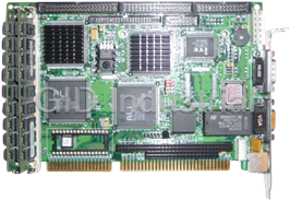
486DX5-133 Half-size CPU Card with LCD, Ethernet, & SSD
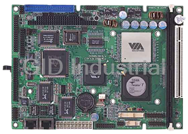
VIA C3 / Eden Low Power Processors
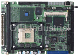
Compact Board with Intel Pentium 4/ Celeron Processors
Entry Level Intel Xeon Server Board, UDIMM RAM/VGA/GbE x 2 LAN/2 USB
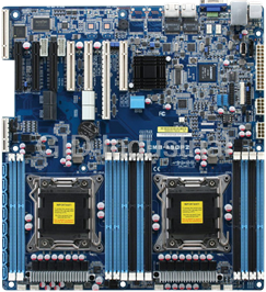
High Performance Server Board with Dual Intel Xeon Processors, RDIMM/UDIMM/LRDIMM RAM, VGA, 2 GbE LA...
Request a Quote

The quote request has been received
Close

Facing challenges or have inquiries? Feel free to contact us!
Call Us +1-469-283-2440
What they say about us
FANTASTIC RESOURCE
One of our top priorities is maintaining our business with precision, and we are constantly looking for affiliates that can help us achieve our goal. With the aid of GID Industrial, our obsolete product management has never been more efficient. They have been a great resource to our company, and have quickly become a go-to supplier on our list!
Bucher Emhart Glass
EXCELLENT SERVICE
With our strict fundamentals and high expectations, we were surprised when we came across GID Industrial and their competitive pricing. When we approached them with our issue, they were incredibly confident in being able to provide us with a seamless solution at the best price for us. GID Industrial quickly understood our needs and provided us with excellent service, as well as fully tested product to ensure what we received would be the right fit for our company.
Fuji
HARD TO FIND A BETTER PROVIDER
Our company provides services to aid in the manufacture of technological products, such as semiconductors and flat panel displays, and often searching for distributors of obsolete product we require can waste time and money. Finding GID Industrial proved to be a great asset to our company, with cost effective solutions and superior knowledge on all of their materials, it’d be hard to find a better provider of obsolete or hard to find products.
Applied Materials
CONSISTENTLY DELIVERS QUALITY SOLUTIONS
Over the years, the equipment used in our company becomes discontinued, but they’re still of great use to us and our customers. Once these products are no longer available through the manufacturer, finding a reliable, quick supplier is a necessity, and luckily for us, GID Industrial has provided the most trustworthy, quality solutions to our obsolete component needs.
Nidec Vamco
TERRIFIC RESOURCE
This company has been a terrific help to us (I work for Trican Well Service) in sourcing the Micron Ram Memory we needed for our Siemens computers. Great service! And great pricing! I know when the product is shipping and when it will arrive, all the way through the ordering process.
Trican Well Service
GO TO SOURCE
When I can't find an obsolete part, I first call GID and they'll come up with my parts every time. Great customer service and follow up as well. Scott emails me from time to time to touch base and see if we're having trouble finding something.....which is often with our 25 yr old equipment.
ConAgra Foods