yA,C;KAWA
AC SERVO. DRIVES
BULLETIN
ALL DIGITAL, FOR SPEED CONTROL
SERVOMOTOR: TYPES USAMED, USAFED, USAGED,
USADED, USASEM (With Optical Encoder)
SERVOPACK • TYPE CACR-SRE---_BEI'-____-I
YAS KAWA TSE-S800-11.1 E
YASKAWA all-digital AC Servo Drives provide mechatronics drives for
the most advanced FA and FMS including robots and machine tools. I
These drives are the result of the most advanced servo drive manufac-
turing technology available anywhere in the world.
For your mechatronics systems, take advantage of the flexible
combination of our AC SERVOMOTOR and SERVOPACK to achieve
quick response and smooth, powerful operation even at low-speed
range.
FEATURES
• Compact design and simple wiring
• Stable operation with all digital control
(Stableadjustmentwith parameter) I
"Ira
• Versatile Functions (torque control, soft start, etc)
• High reliability
q
592-77
M Series F Series G Series S Series D Series . SERVOPACK
CONTENTS
1, RATINGS AND SPECIFICATIONS / 1 6.8 APPLICATION / 57
1. 1 RATINGS AND SPECIFICATIONS OF 6.9 MOTOR SPEED AND
M SERIES AC SERVOMOTORS / 1 TORQUE MEASUREMENT / 59
1.2 RATINGS AND SPECIFICATIONS OF 7, USER CONSTANTS I 62
F SERIES AC SERVOMOTORS ! 3
1.3 RATINGS AND SPECIFICATIONS OF 8, MONITOR PANEL OPERATION I 66
G SERIES AC SERVOMOTORS / 5
8.1 SWITCH.OPERATION / 66
1.4 RATINGS AND SPECIFICATIONS OF
S SERIES AC SERVOMOTORS / 7 8.2 FUNCTIONS OF MONITOR PANEL / 67
1.5 RATINGS AND SPECIFICATIONS OF 8.3 STATUS INDICATION MODE / 68
D SERIES AC SERVOMOTORS ! 9 8.4 SETTING MODE / 69
1.6 RATINGS AND SPECIFICATIONS OF 8.5 MONITOR MODE I 85
SERVOPACK I 11 8.6 FAULT TRACEBACK MODE I 87
2. TYPE DESIGNATION I 13 9. INSTALLATION AND WIRING I 89
3. LIST OF STANDARD 9.1 RECEIVING I 89
COMBINATION I 15 9.2 INSTALLATION I 89
9.3 WIRING I 94
4. CHARACTERISTICS I 19
10. DIMENSIONS I 97
4.1 OVERLOAD CHARACTERISTICS I 19
10. 1 SERVOMOTOR I 97
4.2 STARTINGAND STOPPING TIME I 20
4.3 ALLOWABLE FREQUENCY OPERATION I 21 10.2 SERVOPACK I 110
10.3 PERIPHERAL DEVICES I 113
4.4 SERVOMOTOR FREQUENCY / 23
4.5 MOTOR SPEED-REFERENCE
11. TEST RUN I 116
INPUT CHARACTERISTICS I 23
4. 6 MOTOR MECHANICAL 11.1 CHECK ITEMS BEFORE TEST RUN I 116
CHARACTERISTICS I 24 11.2 TEST RUN PROCEDURES I 116
5. CONFIGURATION I 28 12. ADJUSTMENT I 118
5. 1 CONNECTION DIAGRAM I 28 12. 1 CHARACTERISTICS PRESET AT THE
5.2 MAIN CIRCUIT TERMINALS I 29 FACTORY PRIOR TO SHIPMENT I 118
5.3 APPLICABLE RECEPTACLES I 29 12.2 READJUSTMENT I 119 •
5.4 CONNECTOR TERMINAL (1CN) 13. INSPECTION AND
FOR I/O SIGNAL I 30 MAINTENANCE I 120 " "
5.5 CONNECTOR TERMINAL (2CN) FOR
OPTICAL ENCODER CONNECTION I 38 13. 1 AC SERVOMOTOR I 120
5.6 INTERNAL BLOCK DIAGRAM I 40 13.2 SERVOPACK I 121
6. OPERATION I 42 14. TROUBLESHOOTING I 122
6. 1 POWER ON AND OFF I 42 14. 1 SERVOMOTOR I 122
6.2 SPEED REFERENCE I 43 14.2 SERVOPACK I 123
6.3 TORQUE CONTROL / 45
6.4 EXTERNAL CURRENT LIMIT
REFERENCECIRCUIT[P-CL, N-CL]I 48
6.5 PROTECTIVE FUNCTIONS I 50
6.6 PRECAUTIONS FOR APPLICATION I 53
6. 7 PRECAUTIONS FOR OPERATION I 54
i
INDEX
Subject Chapter Section Page
A AC SERVOMOTOR ............................................................................................................... 13 ............... 13.1 ............... 120
AC SERVOMOTOR ............................................................................................................... 9 ................. 9.2.1 .............. 89
ADJUSTMENT ...................................................................................................................... 12 ........................................ 118
ALLOWABLE FREQUENCY OF OPERATION ....................................................................... 4 ................. 4.3 ................. 21
Allowable Radial Load and Thrust Load ................................................................................ 4 ................. 4.6.2 .............. 24
APPLICABLE RECEPTACLES .............................................................................................. 5 ................. 5.3 ................. 29
APPLICATION ....................................................................................................................... 6 ................. 6.8 ................. 59
Application of SERVOMOTORS with Holding Magnetic Brake .............................................. 6 ................. 6.9.2 .............. 61
Auxiliary Input Circuit (_+2 to _+10V) ..................................................................................... 6 ................. 6.2.4 .............. 44
C Cable Specifications ............................................................................................................. 5 ................. 5.5.2 .............. 38
CHARACTERISTICS PRESET AT THE FACTORY PRIOR TO SHIPMENT ........................... 12 ............... 12.1 ............... 118
CHARACTERISTICS ............................................................................................................. 4 .......................................... 19
CHECK ITEMS BEFORE TEST RUN .................................................................................... 11 ............... 11.1 ............... 116
Clearing Fault Traceback Data .............................................................................................. 8 ................. 8.4.5 .............. 78
CONFIGURATION ................................................................................................................. 5 .......................................... 28
I
CONNECTION DIAGRAM ..................................................................................................... 5 ................. 5.1 ................. 28
Connection for Reverse Motor Running ................................................................................ 6 ................. 6.8.1 .............. 59
Connector 1CN Layout and Connection of SERVOPACK ...................................................... 5 ................. 5.4.1 .............. 30
Connector Layout .................................................................................................................. 5 ................. 5.5.1 .............. 38
CONNECTOR TERMINAL (2CN) FOR OPTICAL ENCODER CONNECTION ......................... 5 ................. 5.5 ................. 38
CONNECTOR TERMINAL (1CN) FOR I/O SIGNAL ............................................................... 5 ................. 5.4 ................. 30
Current Limit when Motor is Locked ..................................................................................... 6 ................. 6.4.3 .............. 49
D D Series ..................................... :.......................................................................................... 10 ............... 10.1.4 ............ 105
DIMENSIONS in mm (inches) ............................................................................................... 10 ........................................ 97
Direction of Rotation ............................................................................................................. 4 ................. 4.6,4 .............. 25
q
Examples of Troubleshooting for Defective Wiring or Parts ................................................... 14 ............... 14.2.2 ............ 125
Examples of Troubleshooting for Incomplete Adjustment ...................................................... 14 ............... 14.2.3 ............ 125
EXTERNAL CURRENT LIMIT REFERENCE CIRCUIT [P-CL, N-CL] ...................................... 6 ................. 6.4 ................. 48
F F Series ................................................................................................................................ 10 ............... 10.1.2 ............ 99
FAULT TRACEBACK MODE ................................................................................................. 8 ................. 8.6 ................. 87
G G Series ............................................................................................................................... 10 ............... 10.1.3 ............ 102
H Handling of Speed Reference Input Terminal ....................................................................... 6 ................. 6.2.3 .............. 44
High Voltage Line ................................................................................................................. 6 ................. 6.6,3 .............. 53
,din
I Impact Resistance ................................................................................................................ 4 ................. 4.6.5 .............. 26 •
II
Input Circuit .......................................................................................................................... 5 ................. 5.4.3 .............. 33
Input Signals of Connector 1CN ............................................................................................ 5 ................. 5,4,2 .............. 32
INSPECTION AND MAINTENANCE ...................................................................................... 13 ........................................ 120
Inspection during Test Run ................................................................................................... 11 ............... 11.2.3 ............ 117
INSTALLATION AND WIRING ............................................................................................... 9 .......................................... 89
INSTALLATION ..................................................................................................................... 9 ................. 9.2 ................. 89
INTERNAL CONNECTION DIAGRAM ................................................................................... 5 ................. 5.6 ................. 40
J Jog Function ......................................................................................................................... 6 ................. 6.2,7 .............. 45
L LED Indication (7-segment) for Troubleshooting .................................................................... 14 ............... 14.2.1 ............ 123
LIST OF STANDARD COMBINATION ................................................................................... 3 .......................................... 15
Load Inertia (JL) .................................................................................................................... 6 ................. 6.6.2 .............. 53
M M Series ............................................................................................................................... 10 ............... 10.1.1 ............ 97
MAIN CIRCUIT TERMINALS ................................................................................................. 5 ................. 5.2 ................. 29
Mechanical Specifications ..................................................................................................... 4 ................. 4.6.3 .............. 25
Mechanical Strength ............................................................................................................. 4 ................. 4.6.1 .............. 24
Method of Connection ........................................................................................................... 5 ................. 5.5.3 .............. 39
,ii
Method of Giving External Current Limit Reference .............................................................. 6 ................. 6.4.1 .............. 48 I
II
MONITOR MODE .................................................................................................................. 8 ................. 8.5 ................. 85
Monitor Panel Controlled Operation Mode Selection and Operating Procedure ..................... 8 ................. 8.4.3 .............. 75
MONITOR PANEL FUNCTIONS ............................................................................................. 8 ................. 8.2 ................. 67
MONITOR PANEL OPERATION ............................................................................................ 8 .......................................... 66
INDEX (Conrd)
Subject Chapter Section Page
M Monitor Terminals ................................................................................................................. 6 ................. 6.9.1 .............. 59
MOTOR MECHANICAL CHARACTERISTICS ........................................................................ 4 ................. 4.6 ................. 24
MOTOR SPEED AND TORQUE MEASUREMENT ................................................................ 6 ................. 6.9 ................. 59
MOTOR SPEED-REFERENCE INPUT CHARACTERISTICS .................................................. 4 ................. 4.5 ................. 23
N Noise Control ........................................................................................................................ 6 ................. 6.7.1 .............. 54
O Operation ............... ............................................................................................................... 11 ............... 11.2.2 ............ 117
OPERATION ......................................................................................................................... 6 .......................................... 42
Output Circuit ................................................................................... :................... "................ 5 ..... : ........... 5.4.5 ,. ............ 36
Overhanging Loads .......... _..................................................................................... ,............... 6 ................. 6.6.1 .............. 53
OVERLOAD CHARACTERISTICS ......................................................................................... 4 ................. 4.1 ................. 19
P PERIPHERAL DEVICES in mm (inches) ............................................................... ................ 10 ............... 10.3 ............... 113
Power Line Protection .......................................................................................... :................ 6 ................. 6.8.2 .......... :... 57
Power Loss ........................................................................................................................... 9 ................. 9.3.3 .............. 84
PRECAUTIONS FOR APPLICATION ..................................................................................... 6 ................. 6.6 ................. 53
PRECAUTIONS FOR OPERATION ....................................................................................... 6 ................. 6.8 " 57
Preparation for Operation ....................... , .............................................................................. 11 ............... 11.2.1 ............ 116
D POWER ON AND OFF .......................................................................................................... 6 6.1 ................. 41
PROTECTIVE FUNCTIONS .................................................................................................. 6 ................. 6.5 ................. 50
R Rated Current and Cable Size ... ........................................................................................... 9 ................. 9.3.1 .............. 94
RATINGS AND SPECIFICATIONS OF SERVOPACK ............................................................ 1 ................. 1.6 ................. 11
RATINGS AND SPECIFICATIONS ........................................................................................ 1 .......................................... 1
READJUSTMENT ................................................................................................... _............. 12 ............... 12.2 ............... 119
RECEIVING ............................................... •........................................................................... 9 ................. 9.1 ................. 89
SERVOMOTOR FREQUENCY .............................................................................................. 4 ................. 4.4 ................. 23
D S S Series ................................................................................................................................ 10 ' 10.1.5 ............ 106
SERVOMOTOR ..................................................................................................................... 10 ............... 10.1 ............... 97
SERVOMOTOR ..................................................................................................................... 11 ............... 11.1.1 ...: ........ 116
SERVOMOTOR .................................... -......... ".......... :........ -................................................... 14 ............... 14.1 ............... 122
Set Voltage and Current Limit Values ................................................................................... 6 ................. 6.4.2 .............. 49
SETTING MODE ............................................................................. : ..................................... 8 ................. 8.4 .......... :...... 69
Soft Start Function ................................................................................................................ 6 ................. 6.2.6. ............. 44
Specifications of Connector Terminal (2CN) for Encoder ....................................................... 5 ................. 5.3.2 .............. 29
Speed Control with Zero Clamp ............................................................................................ 6 ' 6.2.5 .............. 45
Speed Reference Circuit ....................................................................................................... 6 ................. 6.2.1 43
Speed Reference Offset Adjustment ..................................................................................... 8 ................. 8.4.4 .............. 77
D Specifications of Connector Terminal (1CN) for Input/Output Signal ..................................... 5. ................ 5.3.1 .............. 29
SPEED REFERENCE ............................................................................................................ 6 ................. 6.2 ................. 43
STARTING AND STOPPING TIME ...................................................................................... :. 4 ................. 4.2 ................. 20
STATIJS INDICATION MODE ............................................................................................... 8 ................. 8.3 ................. 68
SWITCH OPERATION .................................................................... :...................................... 8 ................. 8.1 ................. 66
T TROUBLESHOOTING ........................................................................................................... 14 ........................................ 122
TYPE DESIGNATION ........................................................................................... ................. 2 .......................................... 13
U USER CONSTANTS ............................................................................................................. 7 .......................................... 62
V Vibration Class ...................................................................................... : ............................. :. 4 ................. 4.6.7 .............. 26
Vibration Resistance ............................................................................................................. 4 ................. 4.6.6 .............. 26
iii
1. RATINGS AND SPECIFICATIONS 9
1.1 RATINGS AND SPECIFICATIONS OF M SERIES AC SERVOMOTORS
1.1.1 Ratings
Time Rating: Continuous Ambient Humidity: 20% to 80%
Insulation: Class F (non-condensing)
Isolation Voltage: 1500 VAC, one minute Vibration: 15#m or below
Insulation Resistance: 500 VDC, 10Mf_ Finish in Munsell Notation: N1.5
or more Excitation: Permanent magnet
Enclosure: Totally-enclosed, self-cooled Mounting: Flange mounted
(Equivalent to IP-65 exclusive shaft opening) Drive Method: Direct drive
Ambient Temperature: 0 to +40°(; tll
Ii
Table 1.1 Ratings and Specifications of M Series AC SERVOMOTOR
Motor Type USAMED- USAMKD
Item ,,, 03[Z_Z;1 06E-Ell I 09BiLq2 I 12B[_}2 I 20BiZi2 30B[Lq2 44BC12 -60BEi2
0.3 0.6 I 0.9 I 1.2 2.0 3.0 4.4 6.0
RatedOutput* kW(HP) (0.4) (0.8) I (1.2) I (1.6) I (2.7) (4.0) (5.9) (8.0)
N ° m 2.84 5.68 I 8.62 I 11.5 I 19.1 28.4 41.9 57.2
RatedTorque* (Ib.in) (25) . (50) I (76) I (102) I (169) (252) , (372) (507)
I
N- m 2.94 5.88 r 8.82 I 11.8 I 21.6 32.3 46.1 62.9
Continuous Max Torque* (lb. in) (26) (52) I (78) I (104) I (191) (286) i (408) (557)
N • m 7.17 14.1 I 19,3 I 28.0 I 44.0 63.7 ! 91.1 105.8
InstantaneousPeakTorque* (lb. in) (63) (125) I (171) I (248) I (390) (564) ,r (807) (938)
Rated Current* A 3.0 5.8 7.6 I 11.7 I 18.8 26 ,' o,.,'_'_ 45
Rated Speed* r/min 1000
Instantaneous Max Speed* r/rain 2000 1500
N ° m/A 1.01 1.04 1.21 1.02 1.07 1.16 1.33 •
Torque Constant (Ib ° in/A) (8.9) (9.2) (10.7) (9.0) (9.5) (10.2) (11.8)
Moment of Inertia kg .rffxl0" 13.5 24.3 36.7 58.0 110 143 240
JM (= G02/4) (Ib * in * s2xl0 -3) (12.0) (21.5) (32.5) (51.2) (97.2) (126.7) (212.6)
Power Rate* kW/s 6.0 13.3 20.3 22.7 33.2 57.0 74.0 138
InertiaTimeConstant ms 12.8 6.3 4.4 6.0 5.2 3.5 3.6 4.0
InductiveTimeConstant ms 2.7 5.1 6.5 10.4 12.9 15.3 16.2
Insulation Class F
8 1: Values when SERVOMOTOR is combined with SERVOPACK and the armature winding temperature is 20°C.
Shown are normal (TYP) values above.
82: The blank [_-2 of , motor type depends on class of detectors.
Standard: 2 (8192 pulses/rev)
Semi-Standard: 3 (2048 pulses/rev)
Optical eneoder is used as a detector.
Note: The power supply units for brake:
• Input 100 VAC, Output 90 VDC: Type B9400876-2
• Input 200 VAC, Output 90 VDC: Type B9400876-1
For details, see Par. 10.3 (2).
1.1.2 Torque-Speed Characteristics
• TYPE USAMED-03[-] • TYPE USAMED-20B
2000 i _..:,,,,_: _ 2000 _ _#_
1_oo 1_o_ _ _.
SPEED
A _\ s
SPEED g (r/min) 1001 _"
(r/min) 1000 _
50(
_oo 'If _, 11
i _ &% CN.m)
0 21 4 6 i 8 1(_ 20 I 30 A0 .'(N.m)
_) 20 20 60 80 (Ib-in) 0 , 100 200 300 _ 400 (Ib'ln)
RMSTORQUE RMSTORQUE
• TYPE USAMED-06 [-] • TYPE USAMED-30B
SPEED
SPEED B ;_ (r/min) A B
1500 _ _, _ "_ ....
(r/min) lOOO 1000
soo _ 7_
D _oo
0 _ ii; (N-m) :N-m)
() 3, 30 60 99'012 120 15150 (Ib.in) 0 150 300 450 600 (Ib°in)
RMS TORQUE RMS TORQUE
• TYPE USAMED-09B • TYPE USAMED-44B
2000 _ _ 2000i
1500 _ 150C
SPEED , _< B _ SPEED
(r/min) 100C c+_
(r/rain) lOOO " A B
soo _'!"' _oc / _'_
,4 8 12 16 20 (N.m) 20 40 60 _ (N.m)
o do 'ib 1._o"200(Ib'in) 260 4bo 6bo 8_0 ldOO (Ib'in)
RMSTORQUE RMSTORQUE
• TYPE USAMED-12B • TYPE USAMKD-60B
ooo
1_oo/ _ _
i_ SPEED _ "_ _ _ _
SPEED A _ B (r/min) 1000 ....
(r/min) 1000 :_°""
' A
_oo _oo_
ill
0 10 20 _130 r(N'm) 0 20 40 _60 80 100 (N.m)
_) 100 200 300 (Ib'in) 0 _- 2_)O 400 6_)0 8_)O 1(_00(Ib°in)
RMS TORQUE RMSTORQUE
A: CONTINUOUS DUTY ZONE
B: INTERMITTENT DUTY ZONE
POWER SUPPLY: 200 V
I
1 ,2
RATINGS AND SPECIFICATIONS OF F SERIES AC SERVOMOTORS 9
1.2.1 Ratings
Time Rating: Continuous Ambient Humidity: 20% to 80%
Insulation: Class F (non-condensing)
Isolation Voltage: 1500 VAC, one minute Vibration: 15/_mor below
Insulation Resistance: 500 VDC, 10M_ Finish in Munsell Notation: N1.5
or more Excitation: Permanent magnet
Enclosure: Totally-enclosed, self-cooled Mounting: Flange mounted
(Equivalent to IP-65 exclusive shaft opening) Drive Method: Direct drive
Ambient Temperature: 0 to +40°C
Table 1.2 Ratings and Specifications of F Series AC SERVOMOTORS
._Motor Type USAFED- 02 .......... 1 03 .......... 1 05 .......... 1 09 .......... lp13C .....2 20Ci 'i2130Cii2 44Cii2
,2 ................................................................................
Item
kW 0.15 i 0.3 ' 0.45 ' 0.85 r 1.3 1.8 2.9 4.4
RatedOutput* (HP) (0.2) (0.4) (0.6) . (1.1) (1.7) . (2.4). (3.9) (5.9)
N°m 0.98 1.96 2.84 5.39 8.34 11.5 18.6 28.4
RatedTorque* (Iboin) (8.7) (17) (25) (48) (74) . (102) 1(165) (252)
N°m 1.08 ' 2.16 2.94 5.88 ' 8.83 11.8 } 22.6 37.3
Continuous Max Torque* (ib°in) (10) (19) (26) (52) (78) , (104) I (200) (330)
N°m 2.91 ' 5.83 8.92 15.2 24.7 34.0 I 54.1 76.2
InstantaneousPeak Torque* (lb-in) (26) (52) (79) , (135) (219) (301) I' (479) (675)
Rated Current* A 3.0 3.0 3.8 6.2 9.7 15 20 30
Rated Speed* r/rain 1500
Instantaneous Max Speed* r/rain 2500
N°m/A 0.36 0.72 0.80 0.92 0.92 0.82 0.98 1.02
Torque Constant (Ib* in/A) (3,2) (6,3) (7,1) (8,2) (8,2) (7,3) (8.7) (9.0)
Momentof inertiajM(=GD=/4 ) kg°m2Xl0 -4 1.3 2.06 13.5 24.3 36.7 58 110 143
(Ib.in.s_ X10-3) (1.2) (1.8) (12.0) (21.5) (32.5) (51.2) (97.2) (126.7)
,din
Power Rate .1 kW/s 7.4 18.3 6.0 12 18.9 22.7 31.5 57.0 q
Inertia Time Constant ms 3.9 2.5 10.9 6,0 4.4 5.9 5.2 3.7
Inductive Time Constant ms 3,4 4.3 3.2 5.2 6.1 10.4 13.0 15.2
Insulation Class F
h Values when SERVOMOTORis combined with SERVOPACK and the armature winding temperature is 20°C.
Shown are normal (TYP) values above.
$2: The blank [:] of motor type depends on class of detectors.
Standard: 2 (8192 pulses/rev)
Semi-Standard: 3 (2048 pulses/rev)
Optical encoder is used as a detector.
Note: The power supply units for brake:
• Input 100 VAC, Output 90 VDC: Type B9400876-2
. Input 200 VAC, Output 90 VDC: Type B9400876-1 •
For details, see Par. 10.3 (2).
1
-3-
D 1.2.2 Torque-Speed Characteristics .-
• TYPE USAFED-02[_] • TYPE USAFED-13C
2000
2000
SPEED ]500 ,_ SPEED 1500
A _J '"
(r/min) 1000 _; .B _ (r/min) 4_ B
500
[ _ ' , 500 0o0
o _ _ I
1r 2 I 3 I (N.m) 0 (N.m)
() 10 20 30 (Ib-in) 0 50 100150 200250 (Ib.in)
RMS TORQUE RMS TORQUE
2500 "_J i',_ 2500 _._: ,{
D • TYPE USAFED-03 r-] • TYPE USAFED-20C
_ooo Iii _-'_ .... _
SPEED 150O A_i_ Bi t_: SPEED 1500
(rlmin) 1000 ._ 2000
,ooi i_ 500 I
°i I !_ (rlmin) I000 A] l_I
o o I
_) 21 4 I 6 I (N.m) 10 20. 30 4'0 (N-m)
20 40 60(Ib.in) 0 100 200 3_)0 400'(Ib.in)
RMS TORQUE RMS TORQUE
D • TYPE USAFED-05[-] • TYPE USAFED-30C
_oo o___ _oo o_ ,,:_
2000 I "" 2000
SPEED _500 ' " SPEED 1500
(r/min) p . ,_I (r/min) A_t B [,_
I000 _ " _I 1000
500
II ill
0 I 2j 4 I 6 I 8 I 10 (N-m) 0 20i 40 r 601 (N.m)
0 20 40 60 80 (Ib.in) () 200 400 600 (Ib.in)
RMS TORQUE RMS TORQUE
• TYPE USAFED-09[-] • TYPE USAFED-44C
25oo ............. 2500 i_
SPEED 1500 ! SPEED 1500
(r/rain) B _ (r/min) ,_ _ B {_
1000 i 1000 _ _
_oo 500 _
0 I 51 1% 15 I (N.m) 0 20 40 60 801 (N.m)
0 50 1OO ]50 [Ib.in) 0 200 400 500 800 (Ib-in)
RMS TORQUE RMSTORQUE
A: CONTINUOUS DUTY ZONE
B: INTERMITTENT DUTY ZONE
POWER SUPPLY: 200 V
-4-
1.3 RATINGS AND SPECIFICATIONS OF G SERIES AC SERVOMOTORS t
1.3.1 Ratings
Time Rating: Continuous Ambient Humidity: 20% to 80%
Insulation: ClassF (non-condensing)
Isolation Voltage: 1500 VAC, one minute Vibration: 15#m or below
Insulation Resistance: 500 VDC, 10M9 Finish in Munsell Notation: N1.5
or more Excitation: Permanent magnet
Enclosure: Totally-enclosed, self-cooled Mounting: Flange mounted
(Equivalent to IP-65 exclusive shaft opening) Drive Method: Direct drive
Ambient Temperature: 0 to +40°C
Table 1.3 Ratings and Specifications of G Series AC SERVOMOTORS I
.Ii
Motor Type USAGED- D2Fi!il103!1111 05 .......... 1109 .......... 1113A .....2 20A i 2130A i!2144A i] 2
Item ,2 ............................................... , ..............
kW 0.15 I 0.3 0.45 I 0.85 I 1.3 I 1.8 2.9 I 4.4
Rated Output* (HP) (0.2) I (0.4) (0.6) 1 (1.1) I (1.7)F (2.4)' (3.9) 1(5.9)
N-m 0.98 I 1.96 2.84 I 5.39 I 8.34 I 11.5 18.6 I 28.4
Rated Torque* (Ib.in) (8.7)!(17) (25) I (48)I (74)I (102)' (165) 1(252)
N.m 1.08 ' 2.16 2.94 I 5.88 I 8.83 I 11.8 22.6 I 37.3
Continuous MaxTorque* (Ib,in) (10) (19) (26) I (52) I (78) I (104) , (200) I (330)
N,m 2.9 5.83 8.92 I 13.3 I 23.3 I 28.0 45.1 I 66.2
InstantaneousPeakTorque* (Ib-in) (26) (52) (79) I (:118) I (207)I (248) ' (4()0) I (587) a
'ql
RatedCurrent* A 3.0 3.0 3.8 I 7.6 I 11.7 I 19 24 33
Rated Speed* r/min 1500
Instantaneous Max Speed* r/min 3000
N" m/A 0.36 0.72 0.8 0.8 0.83 0.67 0.80 0.95
Torque Constant (Ib-in/A) (3.2) (6.3) (7.1) (7.1) (7.4) (5.9) (7.1) (8.4)
A_ kg'm2 X10-4 1.3 2.06 13.5 24.3 36.7 57.9 110 143
Momentof InertiaJM(=GD2/_, (ib,in,s _x10_3) (1.2) (1.8) (12.0) (21.5) (32.5) (51.2) (97.2) (126.7)
Power Rate*' kW/s 7.4 18.3 6.0 12 18.9 22.7 36.5 57.0 q
Inertia Time Constant ms 4.5 2.5 10.9 6.1 4.3 5.8 5.2 3.4
Inductive Time Constant ms 3.4 4.3 3.2 5.2 6.7 10.6 13.2 15.9
Insulation Class F
* 1: Values when SERVOMOTOR is combined with SERVOPACK and the armature winding tempm:ature is 20°C.
Shown are normal (TYP) values above.
*2: The blank [_-]of motor type depends on class of detectors.
Standard: 2 (8192 pulses/rev)
Semi-Standard: 3 (2048 pulses/rev)
Optical encoder is used as a detector.
Note: The power supply units for brake:
• Input 100 VAC, Output 90 VDC: Type B9400876-2
• Input200VAC,Output90VDC: TypeB9400876-1 •
For details, see Par. 10.3 (2).
1
1.3.2 Torque-Speed Characteristics
• TYPE USAGED-02[_] • TYPE USAGED-13A
I i
3000
i_I = _ii _ "_ _ _= _ , 300G _ I_ ,: _= I ,
2000 _:; 2000 .....
(r/min) A :_:i, B i: A_
iooo _ _/:
0 1'.0 2.O 3.0 (N.m) 0 " 10 20 30 (N.m)
• I I I I
}O 20 30 (Ib.in) 0 100 200 300 (Ib-in)
RMSTORQUE RMS TORQUE
• TYPE USAGED-03F_-] • TYPE USAGED-20A
SPEED (r/Tin) 3000 "2000_I ,_ _'_'C_ B:::_°ii_ '_!_ (rlmin)SPEED 30°01 _i!2°°°i _....B'_:_'_i_i_" _!
,ooo _ _;
i 1000 ....
o ' _ o _;
10 20 30 (N.m)
2.0 4.0 6.0 (N.m)
I I I L 1_)0 ( I
_) 20 40 60 (Ib.in) 0 200 300 (Ib-in)
RMS TORQUE RMS TORQUE
I • TYPE USAGED-05[_] • TYPE USAGED-30A
2000 : "_?_ 2000 ..... }4
(r/min) B
(r/min) B
lOOO _ _::_'
s,:,EEO E SPEED
1:"--
_1 _!' ,ooo ........ [ _il
o i_ o .... 4
3.0 6.0 9.0 (N.m) 20 40 60 (N.m)
3o 6o 9o (Ib-in) 0 2 0 4oo 6oo (Ib-in)
RMSTORQUE RMSTORQUE
• TYPE USAGED-09[_] • TYPE USAGED-44A
SPEED SPEED
30OO 2000 __ _! ..... '"4_ _ii I 30OO 2000 __ = :__
(r/min) ] B! (r/Tin) B [_iI
25 50 75 (N-rn)
5 10 15 (N.m)
75o (Ib-in)
' _o ' _ 2_o_o '
0 50 150 (Ib.in)
RMS TORQUE RMS TORQUE
A: CONTINUOUS DUTY ZONE
B: INTERMITTENT DUTY ZONE
POWER SUPPLY: 200 V
-6-
1.4 RATINGS AND SPECIFICATIONS OF S SERIES AC SERVOMOTORS
1.4.1 Ratings
Time Rating: Continuous Ambient Temperature: 0 to +40°C
Insulation: Class B (Types USASEM-02A[-]2, Ambient Humidity: 20% to 80%
-03A[-__ 2, -05A[-_I 2) (non-condensing)
Class F (Types USASEM-08A[-31, Vibration: 15#m or below
-15A_-_11, -30A[:]l) Finish in Munsell Notation" N1.5
Isolation Voltage: 1500 VAC, one minute Excitation: Permanent magnet
Insulation Resistance: 500 VDC, 10Mfl Mounting: Flange mounted
or more Drive Method: Direct drive
Enclosure: Totally-enclosed, self-cooled
(Equivalent to IP-44 exclusive shaft opening)
Table 1.4 Ratings and Specifications of S Series AC SERVOMOTORS I
Motor Type USASEM-
02A i....j 2 03A i.....i2 05A i....j 2 08A i.....j1 15A !.....!1 30A L....I 1
Item
kW 0.15 0.31 0.46 0.77 1.54 3.08
RatedOutput* (HP) (0.2) (0.4) (0.6) (1.0) (2.1) (4.1)
N,m 0.49 0.98 1.47 2.45 4.90 9.81
Rated Torque* (Ib-in) (4.3) (8.7) (13) (22) (43) (87)
N, m 0.57 1.18 1.67 3.33 6.18 12.2
Continuous MaxTorque* (Ib,in) (5.0) (10) (15) (30) (55) (108)
N• m 1.47 2.94 4.02 7.35 13.7 29.0
I
Instantaneous PeakTorque* (Ib,in) (13) (26) (36) (65) (122) (257)
Rated Current* A 2.1 3.0 4.2 5.3 10.4 19.9
Rated Speed* r/min 3000
Instantaneous Max Speed* r/min 4000
N •m/A 0.25 0.35 0.37 0.51 0.50 0.53
Torque Constant (Ib,in/A) (2.1_1) (3.10) (3.25) (4.49) (4.43) (4.64)
Momentof InertiaJM(=GD2/4) kg'm2XlO-' 0.13 0.51 0.75 2.85 3.25 5.74
(Ib,in,s2x10-3) (0.11) (0.45) (0.67) (2.53) (2.88) (5.09)
Power Rate.1 kW/s 18.5 18.9 28.9 21 74 167
Inertia Time Constant ms 1.8 2.2 1.8 1.9 0.7 0.4
InductiveTimeConstant ms 1.5 2.7 3.1 6.2 13 26
Insulation Class13 Class F
* Values when SERVOMOTOR is combined with SNRVOPACKand the armature winding temperature is 100°C.
Shown are normal (TYP) values above.
1 Values when SERVOMOTOR is combined with SERVOPACK and the armature winding temperature is 20°C.
Shown are normal (TYP) values above.
The blank i:5 of motor type depends on class of detectors.
Standard: 3 (2048 pulses/rev)
Semi-Standard: 4 (2500 pulses/rev)
OpLical encoder is used as a detector.
Note: The power supply units for brake:
• lnpul_ 100 VAC, Output 90 VDG: Type B9400876-2
• Input 200 VAC, Output 90 VDC: Type B9400876-1
For details, see Par.10.3 (2)
I 1.4.2 Torque-Speed Characteristics
• TYPE USASEM-02A • TYPE USASEM-08A
I
I
4000 _ _,_ __ _;_ 4000 __ :_" _'_i! _1%_
300C ' 3000 !_'- '_
# SPEED
SPEED A B _,
100C ;_ii_ 1000 _1
(rlmir0, • 200¢ II! _,_ ° (r/min) 2000 i t _i_ l :ii_
I _ (N.m) N-m)
0.5 1.0 1.5 2.0 2 4 68 --.
1'0 1'5 2_)(Ib'in) , _) 20 ' . 410 60 8%(I.b-in)
RMS TORQUE RMSTORQUE
• TYPE USASEM-03A • TYPE USASEM-15A
400C !_/_ _!..... :_,_: _,_ _ 4-000 _ _,.,,_
SPEED SPEED A _ B 4i?
(r/min) 2OOC ,_ " (r/rain) 2000
_oo__ 3ooo _
,oo_ _ooo °
it ii
N (N.m)
1 2 3 4 (N.m) 0 5 10 15
0 ll0 210 30 4%(Ib-in) _) 5/0 1(_0 15(_ (Ib-irf)
•RMS TORQUE RMS TORQUE
• TYPE USASEM-05A • TYPE USASEM-30A
_ooo_ _,,_._ _ooo ........... _,_ -
3000 _ E 3°°° _%_ _!
SPEED
SPEED A _ (r/min) A B _
ooo _,i _ ooo , _
(r/min) 2000 _ • 2000 li, i .i_,._
1 ' 2 3 L4 5 (N.m) 0 lO 20 (N.m)
100 2O0
_} 1'0 210 30 410 510 (Ib.in) _) ( I 30_)(Ib.in)
RMS TORQUE RMS TORQUE
A: CONTINUOUS DUTY ZONE
B: INTERMITTENT DUTY ZONE
POWER SUPPLY: 200 V
-8-
1.5 RATINGS AND SPECIFICATIONS OF D SERIES AC SERVOMOTORS I
1,5.1 Ratings
Time Rating: Continuous Ambient Humidity: 20% to 80%
Insulation: Class F (non-condensing)
Isolation Voltage: 1500 VAC, one minute Vibration: 15_m or below
Insulation Resistance: 500 VDC, 10M_ Finish in Munsell Notation: Nl.5
or more Excitation: Permanent magnet
Enclosure: Totally-enclosed, self-cooled Mounting: Flange mounted
(Equivalent to IP-65 exclusive shaft opening) Drive Method: Direct drive
Ambient Temperature: 0 to +40°C Holding Brake Provided.
Table 1.5 Ratings and Specifications of D Series AC SERVOMOTORS
Motor Type USADED-
05E [iiiiii2 IOE _iiili 2 15Eiiiiiii2 225 [iiiiii2 37E [iiiiii2
Item *2
kW 0.5 1.0 1.5 2.2 3.7
RatedOutput* (HP) (0.67) (1.3) (2.0) (2.9) (5.0)
N.m 2.35 4.81 7.16 10.5 17.7
RatedTorque* (Ib.in) (21) (43) (63) (93) (156)
N°m 3.43 6.37 8.83 13.7 " 21.6
Continuous Max Torque* (Ib.in) (30) (56) (78) (122) (191)
N•m 8.24 16.9 25.1 36.8 61.8
InstantaneousPeak Torque* (Ib-in) (73) (149) (222) (326) (547)
Rated Current* A 3.5 7.9 12.6 16.6 23.3
Rated Speed* r/min 2000
Instantaneous Peak Speed* r/min 2500
N°m/A 0.83 0.69 0.64 0.71 0.82
Torque Constant (Ib.in/A) (7.38) (6.07) (5.64) (6.25) (7.29)
kg.m2Xl0 -4 21, 13i" 32, 24t 62, 59t 83, 80t 148, 145t
M°rnent°flnertiaJM(=GD2/4)(Ib.in.s2Xl0-3) (18.2,11.3 t) (28.6, 21.5t) (54.7, 52.1t) (73.8, 71.1t) (131, 128t)
2.7 7.3 8.2 13 21
Power Rate .1 kW/s 4.4t 9.7t 8.6t 14t 22t
18 7.8 7.1 6.2 4.3
Inertia Time Constant ms 11t 5.9t 6.8t 6.0t 4.2t
InductiveTimeConstant ms 4.4 6.9 9.4 11 15
Insulation Class F
Holding PowerSupply VDC 90
Static Function N.m 8.82 21.56
Brake Torque (lb.in) (78) (191 )
kg 17, 16t 19, 18t 30, 27t 32, 29t 39, 36t
Approx Mass (Ib) (37.5, 35.3t) (41.9, 39.7t) (66.2, 59.5t) (70.6, 64t) (86.0, 79.4t)
• Values when SERVOMOTOR is combined with SERVOPACK Note:
o
and the armature winding temperature is 20 C. Shown are The power supply units for brake:
normal (TYP) values above. • Input: 100 VAC Output: 90 VDC: Type B9400876-2
I Values show those of D series without holding brake. * Input: 200 VAC O(_tput: 90 VDC: Type B9400876-1
For details, refer to Par. 10.3.
The blank ill of motor type depends on class of detectors.
Standard: 2 (2048 pulses/rev)
Semi-Standard: 3 (8192 pulses/rev)
Optical encoder is used as a detector.
-9-
D 1.5.2 Torque-Speed Characteristics
• TYPEUSADED-05E
2ooo _ _+ _° I
2500 % 4
SPEED 15oo _,
(r/min) _ _, B I_;_l _
looo i _4 '
I
500 _\ 1_,_4 L.m,
O 2.5 5 7.5
$ 2t5 50 _5 (Ib.in)
RMS TORQUE
• TYPE USADED-10E
250C
200c _ _'_;_ !_
S_EED 15oo _i _ _
(r/min) 1000
0 5 10 1 (N-m)
0 50 100' 150 (Ib.in)
• RMS TORQUE
• TYPE USADED-15E
200C _ _&_'_ ....... _
. _,:i
sPEED 1500
(r/min) A_ !
100C _:}.
D 2500 _1 _=:'_ _'
5oc "I i-:
C 8 16 24 32 N.m)
_) 1_)O 2_)0 3_)0(Ib'in)
• TYPE USADED-22E RMS TORQUE
D 2500 ......................... + ...........
A B
(r/minSPEED)+ooo It /
moo ' _[ . .
+oo iiflL
0 N '
1f 2,) 3) 40 t .m_
0 100 2()0 300 4_0(Ib.in)
• TYPE USADED-37E RMS TORQUE
SPEED ,500 ,,_'1++_-_
B
(r/Tin)
1000
_:_, _ A: CONTINUOUS DUTY ZONE
_' _ B: INTERMITTENT DUTY ZONE
iN.m)
RMS TORQUE
D () 200 400 600 (Ib.in)
-10-
1.6 RATINGS AND SPECIFICATIONS OF SERVOPACK 9
Table 1.6 SERVOPACK Types and Applicable SERVOMOTORS
SERVOPACK Type CACR- SR02BE SR03BE SR05BE SR07BE SR10BE SR15BE SR20BE SR30BE SR44BE SR60BE
kW 0.2 0.3 0.5 0.7 1.0 1.5 2.0 3.0 4.4 6.0
Max Motor Output (HP) (0.3) (0.4) (0.67) (0.94) (1.34) (2.0) (2.7) (4.1) (5.9) (8.0)
Applicable Optical Encoder Standard 8192pulses/rev (Semi-Standard : 2048 _ulses/rev)
USAMKD-
Type USAMED- -- 03821 -- 06B21 09822 12B22 20822 30B22 44822 6o822
AC kW 0.3 0.6 0.9 1.2 2.0 3.0 4.4 6.0
SERVO- :3utput (HP) -- (0.4) -- (0.8) (1.2) (1.6) (2.7) (4.1) (5.9) (8.0)
MOTOR Rated/MaxSpeed r/rain 1000/2000 (44B2, 60B2 : 1000/1500)
SERVOPACK Type CACR- -- SR03BE12M -- SR07BE12MSR10BE12MSR15BE12MSR20BE12M SR30BE12M SR44BE12M ;R60BE12M
:_ Continuous Output Arms -- 3.0 -- 5.8 7.6 11.7 18.8 26.0 33.0 45.0
Current
/
Max Output Current Arms -- 7.3 -- 13.9 16.6 28.0 42.0 56.6 70.0 80.6 /
Allowable kg.m2xl0 ' 67.5 122 184 334 550 715 1200 1200
JL(=GD_/4) (Ib'il;'s2X]03 ) -- (60) -- (107.5) (162.5) (296) (486) (633.5) (1063) (1063)
Applicable Optical Encoder Standard 8192pulses/rev (Semi-Standard • 2048 3ulses/rev) -
Type USAFED- 02D21 03D21 05C21 -- 09C21 13C22 20C22 30C22 44C22 --
AC kW 0.15 0.3 0.45 0.85 1.3 1.8 2.9 4.4
SERVO-Output (HP) (0.2) (0.4) (0.6) -- (1.1) (1.7) (2.4) (3.9) (5.9) --
MOTOR
Rated'MaxSpeed dmi_ 1500 '2500 --
SERVOPACK Type CACR- SR02BE12F SR03BE12F SR05BE12F -- SR10BE12F SR158E12F SR20BE12F SR30BE12F SR44BE12F --
LL Continuous Output Arms ,3.0 3.0 3.8 -- 6.2 9.7 15.0 20.0 30.0 --
Current
Max Output Current Arms 8.5 8.5 11.0 -- 17.0 27.6 42.0 56.5 77.0 --
Allowable kg,m2xt0 _' 6.5 10.3 67.5 122 184 334 550 572 _
JL (=GD_/4) (Ib.in.s2x]0 3) (5.75) (9) (60) -- (107.5) (162.5) (296) (486) (506.8)
Applicable Optical Encoder Standard 8192pulses/rev (Semi-Standard : 2048pulses/rev) --
Type USAGED- 02C21 03C21 05A21 -- 09A21 13A22 20A22 30A22 44A22 --
AC kW 0.15 0.3 0.45 0.85 1.3 1.8 2.9 4.4
cc SERVO- Output (HP) (0.2) (0.4) (0.6) -- (1.1) (1.7) (2.4) (3.9) (5.9) --
MOTOR
O _ Rated4VlaxSpeedr/min 1500 _3000 --
_) _) SERVOPACK Type CACR- SR026E12E 3R03BE12E 3R05BE12E -- SR10BE12C- SR15BE12G SR20BE12G SR30BE12G SR44BE12G --
> L0 Continuous Output Arms 3.0 3.0 3.8 -- 7.6 11.7 19.0 26.0 33.0 --
u_ Current
MaxOutputCurrentArms 8.5 8.5 11.0 -- 17.0
Allowable kg.m2xl0 -' 6.5 10.3 67.5 122 184 223 393 360 _
JL {=GD_/4) (Ib"in-s_<10"3) (5.75) (9) (60) -- (107.5) (162.5) (197) (347) (315)
Applicable Optical Encoder Standard 2048pulses/rev (Semi-Standard : 2500 )ulses/rev) -
Type USASEM- 02A32 03A32 05A32 -- 08A31 15A31 -- 30A31 -- --
AC kW 0.15 0.31 0.46 0.77 1.54 3.08
SERVO-Output (HP) (0.2) (0.4) (0.6) -- (1.0) (2.1) -- (4.1) -- --
MOTOR
Rated/MaxSpeed r/min 300C 14000 --
.t-
SERVOPACK Type CACR- SR02BE13S SR03BE13S SR05BE13S -- SR10BE13_ SR158E13S -- SR30BE13S -- --
u) Continuous Output Arms 2.1 3.0 4.2 -- 5.3 10.4 -- 19.9 -- -
Current
Max Output Current Arms 6.0 8.5 11.0 -- 15.6 28.0 -- 56.5 - --
Allowable kg,m_xt0" 0.65 2.55 3.8 14.3 16.5 _ 28.7 _ _
JL{=GD,2/4) (Ib'in°s2xl03) (0.55) (2.25) (3.35) -- (12.65) (14.4) (25.4)
Applicable Optical Encoder Standard : 2048pulses/rev (Semi-Standard : 8192 )ulses/rev) -
Type USADED- -- -- 05E32 -- -- 10E32 15E32 22E32 37E32 --
AC kW 0.5 10 1.5 2.2 3.7
SERVO- Output (HP) -- -- (0.67) -- -- (1.34) (2.0) (2.9) (4.9) --
MOTOR
m _,ated/MaxSpeed r/min 2000/2500 --
SERVOPACK Type CACR- -- -- SR05BE13D -- -- SR15BE13D SR20BE13E SR30BE13E SR44BE13E --
IB
O Continuous Output Arms -- -- 3.8 -- -- 7.9 12.6 16.6 23.3 --
Current
Max Output Current Arms -- -- 11.0 -- -- 25.2 40.7 54.0 77.0 --
Allowable kg°m2x | 0 "_ 105 160 31o 415 740 _
JL(=GD_/4) (Ib-in-s2x|03) -- -- (91) -- -- (143) (273.5) (369) (655)
-11 -
Table 1.6 SERVOPACK Types and Applicable SERVOMOTORS (Cont'd)
SERVOPACKType SR02BE SR03BE SR05BE SR07BE SR10BE SR15BE SR20BE SR30BE SR44BE SR60BE
kW 02 03 0.5 07 1.0 15 2.0 30 44 6.0
Max Motor Output (HP) (0.3) (0.4) (0.67) (0.94) (1.34) (2.0:1) (2.7) (4.1) (5.9) (8.0)
Power M__ Circuit Three-phase 200 to 230 VAC+_5°:_50/60 Hz.1
Supply IControl Circuit Single phase 200 to 230VAC +__°_ 50/60 Hz*t
Control Method Three-phase Full-wave Rectifier Transistorized-PWM Control (Sine Wave Drive)
o Feedback Optional encoder (8192 pulses/rev, "2048 pulses/rev)
Ambient Temperature 0 to 55°C*5(for type with cover : 0 to 50°C) .6
_ StorageTemperature -20"(3to +85"C
o_ Ambient and Storage 90% or less (non-codensing)
Humidity
I_ Vibrati°n-resistance/Impact'resistance 5m/s 2 / 20m/s 2 (0 5G/2G)
MountingStructure Base mounted
kg 6.0 7.0 13.5
Approx Mass (Ib) (13.2) (15.4) (29.8)
" I
SpeedControlRange .2 1 : 5000
Load Regulation +0.01% or less at rated r/min
0 to 100%
_ Speed .3 Voltage Regulation
-u Regulation _+10% 0%
_ Temp. Regulation
,-, _+01% or less at rated r/min
co 25 + 25°C
Frequency Response
n < Character stics " 100 Hz (JL:JM)
O Rated Reference Speed Control Mode +6 VDC at rated r/min (forward run at plus reference)
> Speed Voltage Torque Control Mode +3 VDC at rated torque (forward torque generated at plus reference)
Reference
Input Input Impedance Approx 30k_
Circuit Time Constant Approx 70jus
iAuxiliary Reference Voltage +12 VDC at rated r/min (forward run at puls reference)
ReferenceInput Impedance Approx 30k_
_ input,4
._ Circuit Time Constant Approx 70ffs
u) Built-in Reference Power
O ±12VDC±5%,±30mAOutput-able
"---Supply
iOutputP°siti°n ___ Form Line Driver and Open Collector (A-phase, B-phase, C-phase)
PG Pulse) _g R-_atio (1 to N)/N, N=8192, 2048 (by number of optical encoder pulse)
Sequence Input Signal Servo ON, P drive (or torque control zero-clamp drive), F overtravel, R overtravel, alarm reset
Sequence Output Signal Servo ready, TG ON, current limit, servo alarm, alarm code (3-bit ot)tput)
External Current Limit 0 to max current in each of P and N (3V/100% current)
Dynamic Brake Operated at main power OFF, servo alarm, overtravel, etc.
Regeneration Provided (for type SR60BE, separately provided)
_o Applicable Load Inertia JL Up to 2 to 5 times motor inertia .7
Overtravel Prevention DB stop or deceleration stop
u_ Communicationerror, overcurrent(OC),MCCB trip(MCCB), regenerativeerror(RG),undervoltage(UV),overspeed
c Protection avervoltage(OV),overload(OL),originerror, overrun,open phase detection,CPU error(CPU,A/D)
"T
= Indication 7-segment LEDs x 5 figures (Alarm, status, parameter indications)
m
Monitor Output Speed monitor : 2V (4V) ±5%/1000r/min, Torque monitor : 3V (2V) ±10%/100%
JOther functions Torque control, zero clamp, soft start, brake interlock, reverse turn connection, JOG Operate .8
$1. Supply voltage should not exceed 230 V + 10% (253 V) If Motor speed may be changed by voltage variation or operational
the voltage should exceed this value, a step down transform- amplifier drift due to temperature. The ratio of this speed
er is required, change to the rated speed represents the speed regulation due
$ 2. In the speed control range, the lowest speed is defined as the to voltage or temperature change.
condition in which there is t00 % load variation, but not $ 4. Used for application at rated reference voltage other than _+6V.
stopped. $ 5. When housed in a panet, the inside temperature must not ex-
$3 Speed regulation is generally defined as follows: ceed ambient temper ature range. ,
D Speed regulation . No load speed -- Rated speed x 100 (%) $ $ 6. 7. Type When with load cover: JL exceeds CACR-SRE]BE1E][-]-C applicable range, be sure to refer to
Rated speed 6.7.2., "Load Inertia."
@ 8. JOG operation with monitor switch
-12-
2. TYPE DESIGNATION 9
• AC SERVOMOTOR
USAFED - 05C21 [_-3[i_
AC ADDITION SPECIFICATION
SERVOMOTOR • Blank: Standard
' • B: WithBrake
---
SERIES M series--44, 60
• AM: MSeries S series--03to30
• AF : F Series * E: With Brake
• AG: G Series F series--02 to 44
• AS: S Series M series--03to 30
• AD: D Series D series--05to 37
G series--02 to 44
ENCLOSURE _ DRIVEENDSPECIFICATION
• E: Totally-enclosed,
Self-cooled Type • Blank: Standard
• K: Totally-enclosed, • O: Standard (With Brake)
externally Fan-cooled Type • K: With Keyway
• S: With Shaft Seal
MAGNET TYPE J • T: With Keyway & Shaft Seal
• D: Ferrite _" SHAFT TYPE
• M: Rare Earth
• 1: Taper
MOTOR OUTPUT J • 2: Straight
(Table2.1) _" ENCODERSPECIFICATION
DESIGNREVISIONORDER (Table2.4)
(A, B, C ........ (Table 2.2)
1
• SERVOPACK
CA CR - SR05BE 1 2 -.r-_
SERVOPACK SERIES _ -'_ OPTIONAL SPECIFICATIONS
CONTROL TYPE "_ P: With packing
(except type SR60BE)
SR: Speed E: NPin English
i .........
._ C: With cover
OUTPUT
MOTOR
'I
(Table 2.3)
APPLICATION J
B: M, F, G, S, D Series
DESIGNREVISION "
ORDER
A,B,C ........
INPUT FORM J
1: 200V, Analog
ENCODERSPECIFICATION "
(Table 2.4)
APPLICABLE MOTOR
SERIES
• M: M Series
• F : F Series
• G: G Series
• S: S Series ,8
• D: D Series
q
-13-
Table 2.1
Motor Output
M Series F Series G Series S Series D Series
02 -- 0.15kW(0.2HP) 0.15kW(0.2HP) 0.15kW(0.2HP) --
03 0.3kW(0.4HP) 0.3kW(0.4HP) 0.3kW(0.4HP) 0.31kW(0.4HP) --
05 -- 0.45kW(0.6HP) 0.45kW(0.6HP), 0.46kW(0.6HP) 0.5kW(0.67HP)
06 0.6kW(0.8HP) ......
08 -- -- -- 0.77kW(10HP) --
09 0.9kW(1.2HP) 0.85kW(1.1HP) 0.85kW(1.1HP) -- --
10 .... 1.0kW(1.3HP)
12 1.2kW(1.6HP) ....
13 -- 1.3kW(1.7HP) 1.3kW(1.7HP) -- --
15 ..... 1.54kW(2.1HP) 1.5kW(2.0HP)
20 2.0kW(2.7HP) 1.8kW(2.4HP) 1.8kW(2.4HP) -- --
22 .... 2.2kW(2.9HP)
30 3.0kW(4.1HP) 2.9kW(3.9HP) 2.9kW(3.9HP) 3.08kW(4.1HP) --
37 .... 3.7kW(5.0HP)
44 4.4kW(5.9HP) 4.4kW(5.9HP) 4.4kW(5.9HP) -- --
60 6.0kW(8.0HP) ......
Table 2.2
Enc0der Resoluti0n (P/R) Series Type Enc_le Resolution r (P/R) Series Type
USAMED-03C3 USAMED-03B2
-06C3 M to
M -09B3
to USAMKD-60B2
USAMKD-6083 USAFED-02D2
USAFED-02D3 -03D2
• to F -05C2
F -09D3 to
-13C3 -44C2
to 8192 P/R
-44C3 USAGED-02C2
2048 P/R USAGED-02C3 -03C2
to G -05A2
G -09C3 to
-13A3 -44A2
to
-44A3 USADED-05E2
USASEM-02A3 D to
S to -37E2
-30A3
USASEM-02A4
USADED-05E3 2500 P/R S to
D to
-37E3 -30A4
Table 2.3
Motor Output
M series F series G series S series D series
02 -- 0.15kW(0.2HP) 0.15kW(0.2HP) 0.15kW(0.2HP) --
03 0.3kW(0.4HP) 0.3kW(0.4HP) 0.3kW(0.4HP) 0.3kW(0.4HP) --
05 -- 0.45kW(0.6HP) 0.45kW(0.6HP) 0.45kW(0.6HP) 0.5kW(O.67HP)
07 0.6kW(0,8HP) ....
10 0:9kW(I•2HP) 0.85kW(I.IHP) 0.85kW(I•IHP) 0.77kW(10HP) --
15 1.2kW(I.6HP) 1.3kW(I.FHP) 1.3kW(I•7HP) 1.54kW(2.1HP) I•0kW(I.3HP)
20 2.0kW(2.7HP) 1.8kW(2.4HP) 1.8kW(2.4HP) -- 1.5kW(2.0HP)
30 3.0kW(4.1HP) 2.9kW(3.9HP) 2.9kW(3.9HP) 3.08kW(4.1HP) 2.2kW(2.9HP)
4.4kW(5.9HP) 4.4kW(5.9HP) 4.4kW(5.9HP) -- 3,7kW(5,0HP)
6.0kW(8.0HP) ......
Table 2.4
Motor Type Standard (P/R) Semi-standard (P/R)
M Series 2 8192 3 2048
F Series 2 8192 3 2048
G Series 2 8192 3 2048 .
S Series 3 2048 4 2500
D Series 3 2048 2 - 8192
-14-
3. LIST OF STANDARD COMBINATION
Combination of SERVOPACK, AC SERVOMOTORS and Accessories
. • M SERIES SERVOPACK AC SERVOMOTOR Power Capacity*_per Current Capacity per Applicable
(Table 3.1) Type CACR- Type SERVOPACK kVA MCCB or Fuse A Noise Filter
SR03BE12M USAMED-03 B21 0.65 5
SR07BE12M USAMED-06 B21 1.5 8
SR 10 BE 12M USAMED-09 B 22 2.1 8
SR15BE12M USAMED-12 B 22 3.1 10 Good
SR20BE12M USAMED°20 B 22 4.1 12
SR30BE12M USAMED-30 B22 6.0 18
SR 44 BE 12M USAMED-44 B 22 8.0 24 - / 4,-,,
SR60BE12M .3 USAMKD-60 B22 11 32 Poor
• 1: Values at rated load. *2: Made by Tokin Corp. *3: For type CACR-SR60BE, regenerative register unit (JUSP-RA03) is required.
• F SERIES SERVOPACK AC SERVOMOTOR Power Capacity per Current Capacity per Applicable
(Table 3.2) Type CACR- Type SERVOPACK kVA MCCB or Fuse A Noise Filter
SR 02 BE 12 F USAFED-02 D 21
0.65 5
SR03BE12F USAFED-03 D21
SR05BE12F USAFED-05 C 21 1.1 5 -_
SR10BE12F USAFED-09 C 21 2.1 8 Good
SR15BE12F USAFED-13 C 22 3.1 10
SR20BE12F USAFED-20 C22 4.1 12
SR30 BE12F USAFED-30 C 22 6.0 18
Poor
SR 44 BE 12F USAFED-44 C 22 8.0 24 ,-,,n
• G SERIES SERVOPACK AC SERVOMOTOR Power Capacity per Current Capacity per Applicable
(Table 3.3) Type CACR- Type SERVOPACK kVA MCCBor Fuse A Noise Filter
SR 02 BE 12 G USAGED-02 C 21
0.65 5
SR03BE12G USAGED-03 C21
SR 05 BE 12 G USAGED-05 A 21 1.1 5
SR10BE12G USAGED-09 A21 2.1 8 Good
SR15BE12G USAGED-13A22 3.1 10
SR20 BE12G USAGED-20 A 22 4.' 12 e_._ _
SR30BE12G USAGED-30 A22 60 18 Poor
SR44 BE12G USAGED-44A 22 8.0 24
• S SERIES SERVOPACK AC SERVOMOTOR Power Capacity per Current Capacity per Applicable
(Table 3.4) Type CACR- Type SERVOPACK kVA MCCB or Fuse A Noise Filter
SR 02 BE 13 S USASEM-02 A 32
0.65 5
SR03BE13S USASEM-03 A32 _,
SR05 BE13S USASEM-05 A 32 1.1 5
Good
SR10BE13S USASEM-08 A 31 2.1 8
SR15BE13S USASEM-15A 31 3.1 10
SR30BE13S USASEM-30 A 31 6.0 18 Poor
• D SERIES SERVOPACK AC SERVOMOTOR Power Capacity per Current Capacity per Applicable
(Table 3.5) Type CACR- Type SERVOPACK kVA MCCBor Fuse A Noise Filter
SR 05 BE 13 D USADED-05 E 32 1.5 8 _ •
SR15BE13D USADED-10 E32 3.1 10 _"
SR20BE13D USADED-15 E32 4.1 12 Good
SR30BE13D USADED-22 E32 6.0 18
SR44BE13D USADED-37 E32 8.0 24 Poor
-15-
Recommended Noise Filter.2
Power ON/OFF Switch
Type Specifications
LF-305 3-phase 200 VAC class, 5A
LF-310 3-phase 200 VAC class, 10A
Contactor 30A or above
LF-315 3-phase 200 VAC class, 15A
LF-315 3-phase 200 VAC class, 15A
LF-320 3-phase 200 VAC class, 20A
LF-330 3-phase 200 VAC class, 30A Contactor 35A or above
LF-340 3-phase 200 VAC class, 40A
LF-350 3-phase 200 VAC class, 50A Contactor 50A or above
Recommended Noise Filter
Power ON/OFF Switch
Type Specifications
LF-305 3-phase 200 VAC class 5 A
LF-305 3-phase 200 VAC class 5 A
LF-305 3-phase 200 VAC class 5 A Contactor 30A or above
LF-315 3-phase 200 VAC class 15 A
LF-315 3-phase 200 VAC class 15 A
LF-320 3-phase 200 VAC class 20 A
LF-330 3-phase 200 VAC class 30 A Contactor 35A or above
• LF-340 3-phase 200 VAC class 40A
Recommended Noise Filter
Power ON/OFF Switch
Type Specifications
LF-305 3-phase 200 VAC class 5 A
LF-305 3-phase 200 VAC class 5 A
LF-305 3-phase 200 VAC class 5 A Contactor 30A or above
LF-315 3-phase 200 VAC class 15 A
LF-315 3-phase 200 VAC class 15 A
LF-330 3-phase 200 VAC class 30 A Contactor 35A or above
LF-340 3-phase 200VAC class 40 A
LF-320 3-phase 200 VAC class 20 A
Recommended Noise Filter
Power ON/OFF Switch
Type Specifications
LF-305 3-phase 200 VAC class, 5 A
LF-305 3-phase 200VAC class, 5 A
LF-305 3-phase 200 VAC class, 5 A Contactor 30A or above
LF-315 3-phase 200 VAC class, 15 A
LF-315 3-phase 200 VAC class, 15 A
LF-330 3-phase 200 VAC class, 30 A Contactor 35A or abbve
Recommended Noise Filter
Power ON/OFF Switch
Type Specifications
30A or above
D LF-310 LF-315 3-phase 3-phase 200 200VAC VAC class, class, 10 15A A Contactor
LF-320 3-phase 200 VAC class, 20 A
LF-330 3-phase 200 VAC class, 30 A Contactor 35A or above
LF-340 3-phase 200 VAC class, 40 A
-16-
Specifications of AC SERVOMOTORS, Detectors and Holding Brakes for Connectio_
• MSERIES ACSERVOMOTOR Detector
Receptacle! L-type Straight Cable Receptacle L-type
(Table 3.6) Type Type Plug Plug Clamp Type Plug
USAMED-03 [][_-] 1
MS3102A MS3108B MS3106B MS3057
USAMED-06 [_-][] 1
18-10P 18-10S 18-10S -10A
USAMED-09B [_]2
USAMED-12B[_]2 MS3102 MS3108B
MS3102A MS3108B MS3106B MS3057
USAMED-20BE]2 20-29P 20-29S
22-22 P 22-22S 22-22S -12A
USAMED-30B[_-] 2
USAM ED-44B[_]2 MS3102A MS3108B MS3106B MS3057
USAMKD-60B[]2 * 32-17P 32-17S 32-17S -20A
• F SERIES AC SERVOMOTOR Detector
Receptacle L-type Straight Cable Receptacle L-type
(Table 3.7) Type Type Plug Plug Clamp Type Plug
USAFED-02[_-][-] 1 MS3102A MS3108B MS3106B MS3057
USAFED-03 [-][_] 1 14S-2P 14S-2S 14S-2S 6A
q
USAFED-05 [_-][_] 1
MS3102A MS3108B MS3106B MS3057
USAFED-09 E][] 1 18-10P 18-10S 18-10S -10A MS3102A MS3108B
USAFED-t3C[-]2 20-29P 20-29S
USAFED-20C [:]2
MS3102A MS3108B MS3106B MS3057
USAFED-30C [-] 2
22-22P 22-22S 22-22S -12A
USAFED-44C[-]2
• G SERIES AC SERVOMOTOR Detector
Receptacle L-type Straight Cable Receptacle L-type I
(Table 3.8) Type Type Plug Plug Clamp Type Plug
"18
USAG ED-02[-][_] 1 MS3102A MS3108B MS3106B MS3057
USAGED-03 r_-][_-] 1 14S-2P 14S-2S 14S-2S 6A
USAGED4)5 [-]r-] 1
MS3102A MS3108B MS3106B MS3057
USAG ED-09 r_]r_] 1 MS3102A MS3108B
18-10P 18-10S 18-10S -10A
USAGED-13Ar-]2 20-29P 20-29S
USAG ED-20A[_-] 2
MS3102A MS3108B MS3106B MS3057
USAGED-30A[[]2
22-22P 22-22S 22-22S -12A
USAGED-44A[_-]2
• S SERIES AC SERVOMOTOR Detector
Receptacle L-type Cable Receptacle L-type Cable
(Table 3.9) Type Type Plug Clamp Type Plug Clamp
USASEM-02A[_-]2 -- -- --
USASEM-03A[_-]2 MS3102A MS3108B MS3057
USASEM-05A[_] 2 18-10P 18-10S -10A MS3102A MS3108B MS3057
USASEM-08A[_-]2 20-29P 20-29S -12A
MS3102A MS3108B MS3057
USASEM-15A[:]2
20-4P 20-4S -12A
USASEM-30Ar-]2
• D SERIES AC SERVOMOTOR Detector
Receptable L-type Straight Cable :Receptacle L-type
(Table 3.10) Type Type Plug Plug Clamp Type Plug
USADED-05E[_]2 MS3102A MS3108B MS3106B MS3057
USADED-10EL-]2 20-15P 20-15S 20-15S -12A
USADED-15EL]2 MS3102A MS3108B
MS3102A MS3108B MS3106B MS3057 20-29P 20-29S
USADED-22EE]2 24-10P 24-10S 24-10S -16A
q
USADED-37E[_]2
-17-
D
Holding Brake
Straight Cable Receptacle L-type Straight Cable
Plug Clamp Type Plug Plug Clamp
MS3102A MS3108B MS3106B MS3057
20-15P 20-15S 20-15S -12A
MS3106B MS3057
MS3102A MS3108B MS3106B MS3057
20-29S -12A
24-10P 24-10S 24-10S -16A
MS3102A32-17pIMs3108B32- MS 13 7S _06832-17S MS3057-20A (Motor Side)
MS3102A14S-7P MS3108B14S-7S MS3106B14S-TS MS3057-6A (Brake Side)
Holding Brake
Straight Cable Receptacle L-type Straight Cable
Plug Clamp Type Plug Plug Clamp
14S-6P 14S-6S 14S-6S -6A
D MS3102A MS3108B MS3106B MS3057
MSA3102A MS3108B MS3106B MS3057
MS3106B MS3057
20-15P 20-15S 20-15S -12A
20-29S -12A
MS3102A MS3108B MS3106B MS3057
24-10P 24-10S 24-10S -16A
Holding Brake
Plug Clamp Type Plug Plug Clamp
Straight Cable Receptacle L-type Straight Cable
MS3102A MS3108B MS3106B MS3057
14S-6P 14S-6S 14S-6S -6A
MSA3102A MS3108B MS3106B MS3057
MS3106B MS3057
20-15P 20-15S 20-15S -12A
20-29S -12A
MS3102A MS3108B MS3106B MS3057
24-1OP 24-10S 24-10S -16A
Holding Brake *For type USAMKD-60BI:]2, the followings are required for cooling fan:
Receptacle L-type Cable Receptacle type: MS3102A14S-6P
Type Plug Clamp L-type plug: MS3108BI4S-6S
Straight plug: MS3106B14S-6S
-- -- -- Cable clamp: MS30576A
MS3102A MS3108B MS3057
18-12P 18-12S -10A Notes:
1. The blank [] of motor type depends on classof detectors,
MS3102A MS3108B MS3057
MotorType Standard (P/R) Semi-standard (P/R)
20-17P 20-17S -12A MSeries 2 8192 3 2048
FSeries 2 8192 3 2048
GSeries 2 8192 3 2048
SSeries 3 2048 4 2500
Straight Cable D Series 3 1024 2 8192
Plug Clamp
2: When plugs or clamps are required, contact your YASKAWA represen-
tative. The following connections are provided: soldered type (type MS)
MS3106B MS3057 and solderless type (type JA).
20-29S - 12A
-18-
4. CHARACTERISTICS
4.1 OVERLOAD CHARACTERISTICS
The overload protective circuit built in SERVOPACK prevents the motor and SERVOPACK
from overloading and restricts the allowable conduction time of SERVOPACK. (See Fig. 4.1.)
The overload detection level is set precisely by the hot start conditions at an ambient
temperature of 55°C and cannot be changed.
NOTE
Hot start is the overload characterisitcs when the SERVOPACK is running at
the rated load and thermally saturated.
g
1000
OPERATING
TIME (S)
100
o
2
100 200 300
MOTOR RATED CURRENT (%)
Fig. 4.1 AllowableOverloadCurve
of SERVOPACK
-19-
4.2 STARTING AND STOPPING TIME
The starting time and stopping time of servomotor under a constant load is shown by the
formula below. Viscous or friction torque of the motor is disregarded.
Starting Time:
tr = 104.7× NR (JM + JL) (ms)
Kt,IR (a-/3)
Stopping Time:
tf = 104.7× NR (JM + JL) (ms)
Kt,IR ( a +13)
I Where,
NR: Rated motor speed (r/min)
JM ( = GD_M/4): Moment ofrotor inertia (kg.m 2)
JL ( = GD:/4) : Moment of load inertia (kg.m 2)
Kt: Torque constant of motor (N.m/A)
IR: Motor rated current (A)
= Ip/]R: Acceleration/deceleration current constant
IP: Acceleration/deceleration current
current) (A)
t (Acceleration/deceleration current _ times the motor rated
= IL/IR: Load current constant
IL: Current equivalent to load torque
(Load current /3 times the motor rated current) (A)
I _1 I
ARMATURE I_'m_l. -| I
CURRENT I : t I_:I _ _ _TIME
I , 1
I ' I
_O_OR I
' 1
SPEED / -- TIME
Fig. 4.2 TimingChartof
Motor Armature Current and Speed
-20-
4.3 ALLOWABLE FREQUENCYOF OPERATION I
The allowable frequency of operation is restricted by the SERVOMOTOR and SERVOPACK,
and both the conditions must be considered for satisfactory operation.
• Allowable frequency of operation restricted by the SERVOPACK
The allowable frequency of operation is restricted by the heat generated in the regenera-
tive resistor in the Servopack, and varies depending on the motor types, capacity, load
J (&), acceleration/deceleration current values,, and motor speed. If the frequency of oper-
ation exceeds 60 times/min when load J = 0 before the rated speed is reached, or if it
60
exceeds cycles/rain when JL = JM Xm, contact your YASKAWA representative.
m+l
• Allowable frequency of operation restricted by the SERVOMOTOR
The allowable frequency of operation varies depending on the load conditions, motor run- •
11
ning time and the operating conditions. Typical examples are shown below.
See Par.4.2, "STARTING AND STOPPING TIME" for symbols.
• When the motor repeats rated-speed operation and being at standstill (Fig.4.3).
Cycle time (T) should be determined so that RMS value of motor armature current is lower
than the motor rated current:
- (s)
T> Ip2 (tr + t')9 + I 2ts 1
Where cycle time (T) is determined, values Ip, tr, tf satisfying the formula above,
should be specified.
MOTOR C'U
ARMATURE I: _ _ _:'1 _1_!
I t, _ t, I:_/I | . _...... L TIME
CURRENT I_ :i :r I':_i r_[ I ",H
I i ' i
,;/
SPEED / TIME
Fig. 4.3 Timing Chart of
Motor Armature Current and Speed
-21 -
• When the motor remains at standstill between cycles of acceleration and deceleration
without continuous rated speed running (Fig. 4.4).
The timing chart of the motor armature current and speed is as shown in Fig. 4.4. The
allowable frequency of operation "n" can be calculated as follows:
Kt • IR l /3 2
n = 286.5 × NR (JM + JL) × a a s (times/rain)
MOTOR
ARMATU RE _------ ---1 _ TIME
CURRENT / _S't
i i
MOTOR I I
SPEED J -- TIME
I
Fig. 4.4 Timing Chart of
Motor Armature Current and Speed
• When the motor accelerates, runs at constant speed, and decelerates in a continuing cy-
cle without being at standstill (Fig. 4.5).
The timing chart of the motor armature current and speed is as shown in Fig. 4.5. The
allowable frequency of operation "n" can be calculated as follows.
Kt • IR 1 /'32 •
n = 286.5 × (JM + JL) × ----a a (times/rain)
ec
- ? ? _
AR MOMATU TOR RE I _ _ _
CORR_NT I ', -_tI:!:1 " i_;! --T,ME
I I
MOTOR I I_
SPEED
i - TIME
Fig. 4.5 Timing Chart of
Motor Armature Current and Speed
-22-
4.4 SERVOMOTOR FREQUENCY I
In the servo drive consisting of SERVOPACK and SERVOMOTOR, motor speed amplitude
is restricted by the maximum armature current controlled by SERVOPACK.
The relation between motor speed amplitude (N) and frequency (f) is shown by the
formula below:
o_. Kt , IR
N = 1.52 x (Jg + JL)f (r/rain)
, ,_ MOTOR
+ ,+++++= --, _;/#pE
MOTOR
i SPEED
Fig. 4.6 Timing Chartof
MotorArmatureCurrentand Speed I
4.5 MOTOR SPEED-REFERENCE INPUT CHARACTERISTICS
Fig. 4.7 shows motor speed and input voltage curve when speed reference input terminals
1CN- @ and @ are used. With auxiliary input terminals, 1CN- @ and @, motor speed can
be set to the rating by adjusting user constant Cn-03 [INBGN] as long as input voltage
is within + 2V to _+ 10V. See Fig. 4.8.
The forward motor rotation (+) means counterclockwise (CCW) rotation when viewed
'qm
from the drive end.
RATED ADJUSTABLE WITH
SPEED (+) i-i RATEDSPEED(+)
-- _ _ -- _' ' , , ,
282.-'2/ '2 , 6
VOLTAGE (V) i ',
_ATED _--- - - "-_ RATED SPEED(-)
SPEED (--)
Fig. 4.7 Speed-InputVoltage Fig. 4.8 Speed-InputVoltage d
Characteristics Characteristics when Auxiliary Input
1
Terminals 1CN- @ and @ are used.
-23-
4.6 MOTOR MECHANICAL CHARACTERISTICS
4.6.1 Mechanical Strength
AC SERVOMOTORScan carry up to 300% of the rated momentary maximum torque at
output shaft. (D series up to 350%) .
4.6.2 Allowable Radial Load and Thrust Load
Table 4.1 to 4.5 show allowable loads according to AC SERVOMOTOR types.
Table 4.1 M Series Allowable Radial Load Table 4.4 S series Allowable Radial Load
andThrustLoad andThrustLoad
Motor Type Allowable Allowable Allowable Allowable
USAMED- Radial Load* Thrust Load Motor Type Radial Load* Thrust Load
N(Ib) N(Ib) USASEM- N(Ib) N (Ib)
03[3[]1 490 (110) 98 ( 22)t 02A[_]2 78.4 (18) 39.2 (9)
06r-]r.]l 490 (110) 98 (22) t 03A[.]2 245 (55) 98 (22)
09B[_]2 686 (154) 343 (77) 05A[_]2 245 (55) 98 (22)
12B[_]2 1470 (330) 490 (110) 08A[[]1 392 (88) 147 (33)
20B[-]2 1470 (330) 490 (110) 15A[:]1 490 (110) 147 (33)
30B[_]2 1470 (330) ,490 (110)
30A[_]1 686 (154) 196 (44)
44B[_]2 1764 (397) 588 (132)
USAMKD-60B[_-]2 t 764 (397) 588 (132)
Table 4.5 D Series Allowable Radial Load
Table 4.2 F Series Allowable Radial Load and Thrust Load
and Thrust Load Motor Type Allowable Allowable
Radial Load* Thrust Load
USADED- N (Ib) N (Ib)
Motor Type Allowable Allowable
Radial Load* Thrust Load 05E[-]2 686 (154) 343 (77)
USAFED- N (Ib) N (Ib)
10E[_]2 686 (154) 343 (77)
02[_][-.]1 147 (33) 49 ( 11)t
;"l;"l =15E[-]2 1176 (265) 490 (110)
03 ...... 1 147 (33) 49 ( 11)t
22E[_]2 1176 (265) 490 (110)
05[_][_-]1 490 (110) 98 ( 22)t
I 09 [[][:]1 490 (110) 98 ( 22)t 37E[:]2 1176 (265) 490 (110)
13C[-.]2 686 (154) 343 (57) * Maximum values of the load applied to the shaft
extension.
20C[_]2 1470 (331) 490 (110) t Do not apply the exceeding load because motor cannot be
30CE]2 1470 (331) 490 (110) rotated.
44CE]2 1470 (331) 490 (110)
Table 4.3 G Series Allowable Radial Load
and Thrust Load
Motor Type Allowable Allowable
Radial Load* Thrust Load
USAGED- N (Ib) N (Ib)
02[:][_]1 147 (33) 49 (11)
03[:][-]1 147 (33) 49 (11)
05[:][:]1 490 (110) 98 (22)
I 09[:][_]1 490 (110) 98 (22)
13A[-]2 686 (154) 343 (77)
20AE]2 1470 (331) 490 (110)
30A[[]2 1470 (331) 490 (110)
44A[-.]2 1470 (331) 490 (110)
-24-
_B
4.6.3 Mechanical Specifications
Table4.6 MechanicaSpe l cifications inmm
Accuracy (T.I.R.)t Reference Diagram
Flange surface 0.04
perpendicular to shaft (_ (0.06){
concentric to shaft ® 0.04
Flangediameter _-@L
0.02
Shaft run out © (0.04)*
t T.I.R. (Total Indicator Reading)
t Accuracy for motor types USADED-15E, -22E, and -37E.
* Accuracy for motor types USAMED-44B, USAMRD-60B.
4.6.4 Direction of Rotation
AC SERVOMOTORS rotate counterclockwise (CCW) when viewed from the drive end when
motor and detector leads are connected as shown below.
Fig. 4.9 AC SERVOMOTOR
(1) Connector Specifications for Standard SERVOMOTORS
(a) Motor receptacle (b) Detector receptacle
• M, F, G, S, D Series
• M,F,G,D Series A Phase U
C PhaseW B Channel A output L --
D Frameground C Channel B output M --
O hasev ,
D Channel B output N
• S Series E ChannelC output P --
(Type USASEM-02A) F ChanneI-Coutput R --
G OV S --
Color of Lead Applicable
H + 5VDC T --
Red Phase U
J Frame ground --
White Phase V
Blue Phase W
Green Frame ground
(Types USASEM-03A to 30A)
B Phase V I
C Phase W
O A Phase U
D Frame ground
-25-
(2) Connector Specifications for SERVOMOTOR with Brake
• M, F (except types USAFEM-02, -03), G, • F Series (Types USAFEM-02, -03)
D Series (Brake is provided to all types of
D series as standard.)
B Phase-V F B Phase-V F Braketerminal
C Phase-W G -- C Phase-W
Q hase akete na hase rakete na
D Frame ground D Frame ground
Types without brake of D series
do not use E and F.
• S Series
(Type USASEM-02A) (Types USASEMi03A, -05A) (Types USASEM-08A to 30A)
Color of Lead Applicable _ A PhaseU _ A PhaseU
Red Phase U B Phase V B Phase V
White Phase V C Phase W C Phase W
Blue Phase W D D
Brake terminal -- Brake terminal
Black E E
Brake terminal
Black F Frame ground F Frame ground
Green Frame ground
• Fan terminal connector specifications (Type USAMKD-60BD2)
CONNECTION Power Supply: Single-phase200/200/220V
50/60/60Hz
-- o AlarmContact: OFFwhen fan is runningnormally
D Alarmterminal o ONwhen fan rotation is 1800_+200
r/rain or less.
E Alarm terminal - Whencoolingfan startsrunnL,tg,ONfor
@ Fan,: A , Fan motorm°t°r M[_TO_ FAN li F
SHADING COIL 3 seconds.
F
Contact Capacity: Resistanceload is ll0V max, 0.3A
Fig. 4.10 Fan Terminal Connection
Arrange the main circuit sequence to stop the SERVOMOTOR and fan motor when cooling
fan alarm occurs. (Alarm contact is ON at alarm occurrence).
After alarm occurrence, make sure to stop the SERVOMOTOR and fan motor within
five minutes since SERVOMOTOR self-cooling protection is set to five minutes.
When cooling fan starts running, alarm detection signal turns ON for three seconds.
Therefore, add a delay relay to the circuit for this time setting (three seconds).
-26-
4.6.5 Impact Resistance
When mounted horizontally and exposed to vertical shock impulses, the motor can with-
stand up to two impacts with impact acceleration of 500m/s2 (50G) (Fig.4.11).
NOTE
A precision detector is mounted on the opposite-drive end of AC SERVO-
MOTOR. Care should be taken to protect the shaft from impacts that could
damage the detector.
I VERTICAL
Fig. 4.11 Impact Resistance
4.6.6 Vibration Resistance
When mounted horizontally, the motor can withstand vibration (vertical, lateral, axial) of q
25m/s2 (2.5G) (Fig.4.12).
I VERTICAL
l ]_IZONTAL
Fig. 4.12 Vibration Resistance 9
4.6.7 Vibration Class
Vibrationof the motor running at rated speed is 15 #m or below (Fig.4.13).
POSITION FOR
CHECKING VIBRATION
Fig. 4.13 Vibration Checking
-27 -
5. CONFIGURATION
5.1 CONNECTION DIAGRAM
POWER SUPPLY
200 TO +10%
230V -ls%
50/60Hz
1 MCCB
Prevent external noise with a noise filter.
Bold lines indicate power lines
NOISE FILTER (excluding the grounding
_-I line).
OFF _L __ (Refer to Table 3.1)
Be sure to fit a surge suppressing
+ _// _" POWER Q-'Q5Ry _ INDICAT_T /S RER OUBLE VO '_ _M CO AG NN TA ETI CT CoREXA OF M IN PL DICA ES TION
t POWER ON 5Ry /FOR POWER ON/OFF
device to both the magnetic contact
1MC l SUP and the relay•
i
,,,..... _ :_:
SERVOPACK
: TYPE AU_M
MAIN.
I TERMINALS
Mustbe
• rounded.
,,-- 4CREMENTA
LENG_
3METERS OR , I
SHORll_ _ I !
SPEED I I
REFERENCE L
ov
LEAD LENGTH:
20METERS ORLESS
CONNECTING CABLE:
No.DPg40O(OFo R 4
A@, B@,C¢ 1-3sPRO No,DE84(X]093
i-36 _PBO
t YASKAWA DRAWING--
®
8esure _ pe_ _
1 Ry _a_nt d st_ded c_e,
Use relays highly reliable
contact (Yaskawa Bestact 2 R.__y
relays or equivalent or arrange YC
in two contact parallel connec-
tion for low level.)
Y4
5Ry I RESISTER UNIT* I POWER
i
(TYPE JUSP-RA03) ........
For motor with
brake.
See Par. 10.3 (2),
"Power Supply for
+ Brake".
Connect the output relay surge absorbing diode with the correct polarity.
+24V+ lV (If connection is wrong, output transistor is damaged.)
(SUPPLIED BY USER)
SERVOPACK is SR6OBE,
I *Added only when type
Fig. 5.1 Example of Connection Diagram of SERVOPACK
with a SERVOMOTOR and Peripherals
28
5.2 MAIN CIRCUIT TERMINALS I
Table 5.1 shows the specifications of main circuit terminals for SERVOPACK.
Table 5.1 Main Circuit Terminals for SERVOPACK
TerminalSymbol Name Description
(_) (_ (_ Main-circuit AC input Three-phase 200 to 230 VAC +__o O/o,50/60 Hz.
Connects terminal @ to motor terminal A,
(_) (_) @ Motor connection @ to B and @ to C.
@ (_) Control power input Single-phase 200 to 230 VAC +_1o o/o,50/50 Hz.
Connects to motor terminal D.
@ Frame ground Must be securely grounded.
External connection not normally required. I
@ @ Regenerative resistor
(Connection required for type SR60BE.)
@@ (_ Fan connection Connects only for types SR60BE.
5.3 APPLICABLE RECEPTACLES
5,3,1 Specifications of Connector Terminal (1CN) for Input/Output Signal t
Table 5.2 Specificationsof ApplicableReceptacles for
SERVOPACK I/O Signals
Applicable Receptacle Type
ConnectorType*
used in SERVOPACK
Manufacturer Soldering Type Caulking Type Case
MR-50RMA4 Honda Tsushin MR-50F* MRP-50F01 MR-50Lt
(Right angle 50P) Co.,Ltd.
'I
* The connectors for 1/Osignals used are type MR-50RMA made by Nonda Tsushin Co.
1 Attached to SERVOPACKprior to shipment.
5,3,2 Specifications of Connector Terminal (2CN) for Encoder
Table 5.3 Specificationsof ApplicableReceptacles for
SERVOPACK Encoder
Connector Type* Applicable Receptacle Type Specifications of
used in SERVOPACK Manufacturer Soldering Type Caulking Type Case Connecting Cable
Yaskawa Drawing
MR-2ORMA4 Honda Tsushin MR-2OFt MRP-2OF01 MR-2OLt No. B9400064 or
(Right angle 20 P) Co., Ltd. No. DE8400093
*The connectorsfor encoderused are made by HondaTsushinCo.
1
I Attached to SERVOPACK prior to shipment.
-29-
5.4 CONNECTOR TERMINAL (lCN) FOR I/O SIGNAL
5.4.1 Connector lCN Layout and Connection of SERVOPACK
The terminal layout of the SERVOPACK I/O signal connectors (1CN) is shown in
Table 5.4. The external connection and external signal processing are shown in Fi9. 5.2
on page 31.
Table 5.4 Connector 1CN Layout of SERVOPACK
1 2 3 4 5 6 7 8 9 10 11 12 13 14 15 16 17 18
0V 0V 0V PHA CLT CLT +24VS_ TRQ VTG
+ - IN -M -M SG IN-A SG-A IN-B SG-B +12V SG FG
Open Ext Servo SpeedMonitor
0 V for PG CollectorCurrent Limit Power ON Speed ReferenceAuxiliary +12V Frame
A¢
i Output Signal OutputDetection OutputInput Power Torque monitor Input Inbut Out )ut Ground
19 20 21 22 23 24 25 26 27 28 29 30 31 32
TGON TGON P-CO----N AL01 N-OT S-ROY S-ROY SG-
PCO *PCOPHC + _ _ + N-CL NCL --12V SG
Line Driver Open PDrive
Output Collector TG ON Open Reverse Servo Ready ReverseCurrent -12V
OutputSignalOutput input Collector Inhibit
C ¢ C¢ Output Input Output LimitInput Output
33 34 35 36 37 38 39 40 41 42 43 44 45 46 47 48 49 50
I PAO *PAO PBO *PBO PHB ALM ALM
+ ALO2 P-OT ALO3 ALM- SG-
_ _ P-CL PCL -12V SG +12V SG FG
Line Driver Line Driver Open Open Fwd. Open Alarm Fwd. Current -12v +12v Frame
Output Output Collector Servo Alarm Collectorllnhibit Collector Reset
Output Output LimitInput Output Output Ground
A ¢ B ¢ B_ OutputInput OutputInput
Note: For input signal and method of application, refer to Table 5.5 and 5.6.
-30-
SE=VO T,E CAO=-S==::=E PAC= 9
M, F, G, S series: 3.0V-+10%/100% TRQ-M
D series: 2.0V+-10%1100% VTG-M
SPEED MONITOR
TO=OU: F, G, S, DM series:O 2.N 0V+-5,TO= %11000rlmin I 10
M series: 4.0V-+5%/1000rlmin
SPEED REFERENCE INPUT IN-A
(RATED SPEED AT _+6V) SG-A IP 12
131
IN-B
AUX. SPEED REFERENCE 1 14[ [ L_'I: _
INPUT SG-B lP
(RATED SPEED AT --+2 TO +IOV) "1°I
I
CURRENT LIMIT AT REVERSE +j, N-CL
RUNNING (--100%± 10%/+3.0V __- SG-NCL I P
INPUT) P-CL .30_
CURRENT LIMIT AT FORWARD _ SG. PCL_P .44" -
RUNNING (+100%±10%/--3.0V --
INPUT) so
+24VlN _-....
SERVO ON AT z4v 1Ry S-ON
I -' --SERVOON
-8 _..... "; PROPORTIONAL
PROPORTIONALCONTROL R =1:: -- CONTROL
AT 2 Ry ON (PI DRIVE AT OFF) _ P-CON -24 #..... J (P DRIVE)
1 Ry ON ___ -"
REVERSE RUNNING _:_S N-OT ==E : - REVERSE RUNNING
INHIBIT AT N-LS OFF i .Z6 1,4--_===_ PROHIBIT
FORWARD RUNNING L_.-LS P-OT _ _,=;_ = PROHIBITFORUNN RWARD ING
INHIBIT AT P-LS OFF _ -41 ......
/gRy
_=K,.'. - ALARM RESET
ALARM RESET
Lo-- _ ALM-RST -- _ ;I ]
AT 9 Ry ON
" 43 r .....
CURRENT
.=.ti LIMIT
LIMIT DETECTION :' CLT-- , p _¢ 5
3Ry ON AT CURRENT 24vi _, CLT+ t _'_'I:[ I}
4Ry TCON+ "I/1}-6 - -_ DETECTION (CLT)
4 TG Ry ON ON AT .",_ -,-_ -_ TGON- I P _,iL52 _ i - TG ON (TGON)
SERVO ALARM _' ALM-- I P i - SERVO ALARM (ALM)
SERVO READY _ S-RDY- I P _-=_i - - SERVO READY
6 Ry ON AT _ _ S-RDY+ _1{- _ t
{S-RDY)
PAD ,".... ,_ J
PHASE-A ( , *PAD i i I P I'] -33 PHASE-A
PBO _ -34
I
PHASE-B
PHASE-B
_. * PBO', ',
PCO ', I
PHASE-C( *PCO', I "_ PHASE-C
,' LINEDRIVER
tENTS INC
',: ,TEXAS
75ALS194
PHA " ,,
,,
PG SIGNAL PHB ,
OPENCOLLECTOR ,,
OUTPUT I PHC ' -- +12 i l-I t
l
ALOI 1-,_
ALARM CODE AL02 SC
ALOZ
OUTPUT ALO3
" AL03
ov
I ALO1
OV l-lli
ov -12v_ - 1-_
"I sc
_ s
FC "i
P
Twisted pair wires.
Notes:
1. Each capacity of output circuits is 30VDC, 50mA or less. .._
2. The user must provide the 24V power supply and battery.
I
Fig. 5.2 I/O Signals and Connector IGN
-31 -
5.4.2 Input Signals of Connector 1CN
Table 5.5 Input Signals
Signal Connector Function Description
Name 1CN No.
• Inputting this signal makes the SERVOPACK ready to receive
S-ON 1CN-8 Servo ON speed reference input (+6 V).
• Base block and dynamic brake are cleared.
Proportional drive •Proportional control command to prevent drifting when the
1CN-24 reference motor is left motionless without command input, while the
main circuit is kept energized.
fThree functions\Zero clamp drive •Inputting this signal maintains the motor in servo lock (stop)
can beselected} reference status and prevents the motor from drifting.
P-CON byparameter /
for torque control/ ,,In torque control II mode,.this signal makes the SERVOPACK
\setting. / Changeover command
speed control change torque control to speed control.
Reverse running ,,In the case of linear drive, etc., connect limit switch signal
N-OT 1CN-26 inhibit according to the run direction. This is a normally closed
contact.
P-OT 1CN-41 Forward running
inhibit •Inputting this signal makes the SERVOPACK cancel the
functions and become "normally N-OT" or "normally P-OT".
+24 VlN 1CN-7 24 V •External power supply to 1CN-8, 24, 26, 41 and 43.
Usean external 24 VDC (25 mA min.) power supply.
IN-A 1CN-12(13) Speed command input* At +6.0 V, _+rated speed is obtained.
Aux. command input* At _+2.0V to _+10.0V, _+rated speed is obtained.
IN-B 1CN-14 (15)
• When either of IN-A or IN-B is used, be sure to set the unused input "Zero specification".
N-CL 1CN-29 (30) Current limit at reverse
running reference +3.0 V +10o /100% torque +9V max.
Current limit at forward
P-CL 1CN-44 (45) running reference -3.0 V +10o/100% torque -9V max.
ALM-RST 43 Alarm reset Resets the servo alarm status.
* Torque command input: + 3V/rated torque
-32-
5.4.3 Input Circuit
There are five kinds of input signals: Servo ON, proportional drive, overtravel prevention
and alarm reset. Construct the input circuit using 24V power supply (Fig.5.3). Typical
circuits are shown in Fig. 5.2.
NOTE
The user must provide the 24V power supply:
24VDC _+1V, 25mA or more (approx 5mA/circuit)
• --1'-" "'
5mA
f
0V
Fig. 5.3 Configuration of I/O Circuit
(1) Servo ON [S-ON]
Turning this signal ON activates the power drive circuit of the SERVOPACK main circuit.
The motor cannot be started unless this signal is input (that is, in the servo-OFF
status). When this signal is turned OFF while the motor is running, the motor is stopped
by the dynamic brake. This signal is automatically input by setting bit 0 of user constant
Cn-01. Don't start/stop the motor by servo ON/OFF.
(2) P-CON
This input signal functions as any of the following three signals depending on bits A and
B of user constant Cn-01.
(a) Proportional drive (P drive)
By setting user constant Cn-01 bit A to 0 and B to 0, P-CON input becomes proportional drive.
The drive may drift in open position loop. To avoid this, switch the speed amplifier
from PI drive to P drive after the positioning and the loop gain in the control system drops
and the drift decreases. With several percent of friction load, the motor stops completely.
(b) Zero clamp operation
By setting user constant Cn-01 bit A to 1 and B to 0, P-CON input becomes zero clamp oper-
ation input.
After the motor stops, it may be locked electrically. This function is applicable verti-
cal loads. Continuous operation torque in servo-lock may not exceed 70% of the motor's
rated torque.
(c) Torque/speed control changeover
Setting user constant Cn-01 bits A and B to 1 enters the torque control mode II.
In torque control mode II, this signal switches between torque and speed control.
-33-
(3) P-OT, N-OT (forward overtravel, reverse overtravel)
These input are used to stop the forward running of the motor (counterclockwise when viewed
from the drive end of the motor) and reverse running. When the overtravel prevention
input is not used, connect 1CN-_) and -@ to the 0 V of the external 24 V power supply,
or invalidate this function by setting bit 2 and 3 of user c6nstant Cn-01.
Operation to be performed when an overtravel occurs can be selected from the fol-
lowing four by setting bit 6, 7, or 8 of user constant Cn-01.
(a) Coasting to a stop (Cn-01, bit 6= 1)
When overtravel occurs, the motor coasts to a stop.
(b) DB stop (Cn-01, bit 6=0)
When overtravel occurs, the motor is stopped by the dynamic brake. Whether the brake
is released after the motor stops or not is decided by bit 7 of user constant Cn-01.
D (c) Stop at the torque specified by user constant Cn-01, bit 8 = 1
When overtravel occurs, regardless of speed reference, the internal circuit forcibly changes
speed reference to zero and immediately stops the motor. After the motor stops, it is
released free. Stop torque is decided by Cn-06, emergency stop torque.
, a-
(d) Zero-clamp after stopping at the torque specified by user constant Cn-01, bit 8 = 1
After the motor stops as (c) above, it is held in zero-clamp mode.
D (4) Alarm reset (ALMRST)
This is an external reset signal for servo alarm. Remove the cause of the alarm before restarting
operation. For safety, set a 0V speed reference (torque reference) when inputting the reset
signal.
-34-
5.4.4 Use of Output Signals 9
Table 5.6 Output Signal
Signal Name Connector 1CNNo. Function Description
• Turns OFF when fault is detected.
ALM 38 (39) Servo alarm • For details, refer to Table 6.1, "Fault Detection
Function.
• Turns ON when motor speed exceeds speed set
TGON Rotation detection
22 (23) by userconstant.
(BK)
Brake interlock output • Outputs timing signal of external brake signal.
• N-CL or P-CL used: Turns ON when output
torque reaches the lower level set by N-CL, P-CL
CLT 5 (6) Current limit detection or _ [_M_.
• N-CL or P-CL not used : Turns ON when output
torque reaches the level set by _ _-_.
• Turns ON when main power supply ON and servo
S-RDY 28 (27) Servo ready
alarm OFF.
+12V 16, 48 ] +12V Output • +12V +5% max output current 30mA I
II
OV 17, 32, 47, 49
Power supply • Used with speed command or current input.
-- 12V 31, 46
• M, F, G, S series
(Ratedtorque at ±3.0V) ±10%, +_gv max,load 1 mA max
TRQ-M 9 Torque monitor • D series
(Rated torque at _+2.0V) ±10%, _+gv max, load 1 mA max
• ±2.0V/1000r/min ±5% (F, G, D, S series)
VTG-M 10 Speed monitor • +_4.0V/1000r/min _+5% (M series)
• Load: 1 mA max
,din
PAO 33 PGSignal Output-1 Phase A I
• PAO 34 PG Signal Output-1 Phase
• Pulse after frequency division is output line driver
PBO 35 PG Signal Output-1 Phase B
(MC 3487*).
• PBO 36 PG Signal Output-1 Phase
• To be received by line receiver (MC 3486*).
PCO 19 PG Signal Output-1 Phase C
• PCO 20 PG Signal Output-1 Phase
PHA 4 (1) PG Signal Output-2 Phase A • Open collector output Pulse after frequency division.
PHB 37 (2) PG Signal Output-2 Phase 8 • Max operating voltage: 30VDC
PHC 21 (3) PG Signal Output-2 Phase C • Max output current.: 20 mA DC
ALO1 25 (1) • Open collector output
Alarm Output Code
ALO2 40 (2) • Max Operating voltage: 30V DC
(BCD code)
ALO3 42 (3) • Max output current: 20mA DC I
'II
• Made by Texas Instruments Inc.
-35-
D 5.4.5 Output Circuit
(1) Sequence signal output circuit
There are four non-contact output signals, employing transistors: Current limit detection,
TG ON, Servo alarm, Servo ready, and three alarm codes with open collector output.
Voltage and current specifications are:
Applied Voltage (V max) __ 30V
Conduction Current (Ip) __ 100 mA
NOTE
The output circuit requires a separate power supply of 20mA or below for open
D collector output. It is recommended to use the same 24V power suppy used
for the input circuit (Fig. 5.4).
• [_ SERVOPACK OPTICAL • CURRENT
°_,T,P2T ',i_ COUPLER L,M,OUTPUT T
RELAY [_t Ip TRANSISTOR | ,TGON
_= - F " - - "1""7 ° SERVO
-T
.... s .vo
D "- f_ ' _ I ALARM
FLY-WHEEL / DIODE _[_ READY
(CONNECT THE DIODE
WITH THE CORRECT _i_
POLARJ]-¥.)
Fig. 5.4 Output Circuit
(2) Optical encoder (PG) output circuit
[PAO, ¢PAO, PBO, $PBO, PCO, $PCO]
Phases A, B, and C (original point) signals for the optical encoder, PG are output.
Use these signals as positioning signals. The output signal specifications are as follows:
(a) Signal form
• Two-phase pulse with 90 ° pulse difference (phases A and B)
• Original point pulse (phase C)
(b) Output circuit and receiver circuit
Two types of output circuits are provided: line driver output and open collector output.
Fig. 5.5 shows an example of line driver output.
-36-
I
+5V,
PHASE A --
LINE RECEIVER
(lic)
SN75175"
PHASE B -- B MC3486 o
R: TERMINAL RESISTANCE
(220 TO 4701"I)
C: DECOUPLING CAPACITOR
PHASE C -- C (0.1,uF)
OUTPUT * Madeby TexasInstruments Inc.
LINE DRIVER
MC3487 -5V
0V
0V 0V
SERVOPACK RECEIVER CIRCUIT
(SUPPLIED BY USER)
4
Fig. 5.5 Output Circuit and Receiver Circuit
(c) Output phase (frequency dividing ratio: 1/1)
4
FORWARDRUNNING REVERSERUNNING
PHASEA I _ J PHASEA-_ _ I
p._90o I---190 o
PHASE B--'_ ? _ PHASE B_ _ l---
PHASE C _ - t PHASE C I I _ t
Fig. 5.6 Output Phase
For details of frequency division, refer to Par. 7 (8), "USER CONSTANT".
-37-
5.5 CONNECTOR TERMINAL (2ON) FOR OPTICAL ENCODER
CONNECTION
5.5.1 Connector Layout
Table 5.7 Connector 2CN Layout of SERVOPACK
I av :0v :0v :v:v:vo: I
"8 9 10 11 12 13 "
5.5.2 Cable Specifications
The cables listed in Table 5.8 are available on request. • If required, purchase in units of
standard length.
Table 5.8 Cable Specifications
Connection Soldered Type Caulking Type
YASKAWA
D " B9400064 DE8400093
Drawing No.
Manufacturer Fujikura Cable Co.-
General Double. KQVV- SW KQVV- SB
AWG 22 x 3 C
Specifications AWG 26 x 4 P AWG 26 x 10 P
Finishing ,_7.5 mm t 10.0mm
Dimensions
RRecommende d -,_ For .Soldered Type For Caulking Type
eceptacleType'] _.F _ _
Internal 1 i Blue-
White-
Composition 2 I Yellow-
White
and
Green-
Lead Color 3 I White
4 I Red-
wh,te NOTE
5 I Purple-
White
T_sted 1. When applicable cables listed in Table 5.8
6 I Blue- lair wires
Brown
are used, allowable wiring distance be-
7 i Yellow- tween SERVOPACK and motor is a maxi-
Brown
('Sandard -_ Green- mum of 20 meters.
Brown
lApp licati°n: J Red- 2. The cable applied for 50 m wiring distance
\B9400064 Brown is available on order (Yaskawa drawing
Purple-
10
arown NO. DP8409179). If wiring distance is 20m
Or more, contact your YASKAWA
YASKAWA Standard length: 5m, 10m, 20m
Standard Terminal ends are not provided (without representative.Cables must beassembled
Specifications connectors), by authorized vendor with appropriate
tooling.
-38-
5.5.3 Method of Connection
INCREMENTAL 0.2mm2
ENCODER SERVOPACK
l" q
CABLE B9400064
* 1 ,"f";
!t',
I _ :Twisted pair wires Note: Connector specifications of incremental encoders are as follows.
',,./ connector--Type MS3102A20-29P (Receptacle)
*Made by Texas Instruments Inc. Accessory (not attached)--Type MS3108B20-29S (Angle plug)
Type MS3057-12A (Cable clamp)
Fig. 5.7 Soldered Type Connector 2CN Connection and 1CN Output Processing
11
(When using Connection Cable B9400064)
INCREMENTAL 0.2mm2
ENCODER SERVOPACK .-.,1
i
CABLE DE8400093
•t !',V!
i } i :Twisted pair wires Note: Connector specifications of incremental encoder are as follows.
,..., Connector--Type MS3102A20-29P (Receptacle) A
• Made by Texas Instruments Inc. Accessory (not attached)--Type MS3108B20-29S (Angle plug)
!
Type MS3057-12A (Cable clamp)
Fig. 5.8 Caulking Type Connector 2CN Connection and 1CN Output Processing
(when using Connection Cable DE8400093)
-39-
5.6 INTERNAL CONNECTION DIAGRAM
rn
-40-
-41 -
6. OPERATION
6.1 POWER ON AND OFF
Arrange the sequence so that the power is simultaneously supplied to the main circuit (R,
S, T) and the control circuit (r, t), or supplied to the control circuit first, then to the main
circuit (Figs. 6.1 and 6.2).
POWER oFFPO_ RON sR___y 1M_c l
l-,_-____ o-F_Z:su_ O-I,
1MCCB ,Mc .....
THaEE-PHASE ---_%---m-- --L-____
200TO 2a0VAC---o_ _ u,__
2ML_._c F.__ w_._" ;F Fig. 6.1 Connection Example for
u ot _1 Simultaneous Control Power ON/OFF
- " POWER OFFPOW _"O_ N_ sR _ _y 1MC I
" 1MCCB _.D-____::) _UP
I I 1MC 1MC
..... "....... I :_R U 1SLIP,2SUP: Surge suppressor
20T 0O 2avAc o ---o_ i &, u-,.5_--VZ_
(50'60 Hz) ----o_'_, _r SERVOPAOK W_ 1D: Flywheel diode (to prevent 5Ry spike)
r v,i
I ' _i _!t Fig. 6.2 Connection Example for
_-__i Main-circuit Power ON/OFF
24VOC _ _ _ --(SERVOALARM)_; I
-, '_ Q_t_Ta__]
Arrange the sequence so that the power is simultaneouly cut (including momentary
power failure) (Fig. 6.1), or the power to the main circuit is cut first, then the control circuit
(Fig. 6.2). The order is the reverse of the power ON sequence.
Precautions for Connections in Figs. 6.1 and 6.2
• Make sequence to assure that the main circuit power will be cut OFF by a servo alarm signal.
(Alarm is written on DPROM, so when the main and control power are turned OFF simultane-
ously, the alarm contents can be checked if the control power is turned ON again.)
• When power is supplied in the power ON/OFF sequence shown in Fig. 6.1, the normal signal is
set (5Ry is turned ON) in the control circuit after a maximum delay of 3 seconds.
NOTE
When the power is turned ON, a servo alarm signal continues for approximately 3
seconds to initialize the SERVOPACK.
• Since SERVOPACK is of a capacitor input type, large in-rush current flows when the main circuit
power is turned ON (recharging time : 0.5 to 1.0 s.) If the power is turned ON and OFF frequent-
ly, the in-rush current limit resister may be degraded and a malfunction may occur. When the
motor starts, turn ON the speed reference and turn it OFF when the motor stops. Do not turn
the power ON or OFF.
• Before power ON or OFF, turn OFF the "Servo ON" switch to avoid transient troubles.
-42 -
6.2 SPEED REFERENCE I
6.2.1 Speed Reference Circuit
From the SERVOPACK built-in control power (1CN- @ , @ : + 12V, 1CN- @ , @, @ ,
@ : 0V, 1CN-@, @: - 12V) or the external power, the speed reference voltage is given
to 1CN- @ and @ or to 1CN- @ and @ When the SERVOPACK built-in control power
is used, the motor speed fluctuates in the range of + 2% of the speed set value.
The method for giving speed reference voltage is described below.
(1) For accurate (inching) speed setting
1.8kfl (½w OR OVER) resister (with dial MD10-30B4) made by Sakae Tsushin Inc.
r---I
_SERVOPACK 25HP-10B type: Multiple-rotation type, wire wound variable I
ITYPE 25HP-,0B 13
_LOR EQUIVALENTF_ 2
10oo:1 Wire-Wound Variable Resistor is used
12V T 2kfll_j = : 1-12 (1-14)*" (a) When Multiple-rotation Type,
t-13 (1-15)*
! Cosmos Electric.
1 M1 (,} W OR OVER) 1.8kfl ($ W OR OVER) RV30YN type: Carbon-film variable resistor made by Tokyo
I iSERVOPACK
12V RH
TYPE RV3OYN TYPE RV3OYN _ 1_I Note: When a carbon resister is used, great residual resistance
OREQUIVALENT OR EQUWALENT _ remains, so the speed control range becomes approxi-
0.1 kfl 11 SPEED) I mately 500:1.
2kaU_ _ _ o o ; -12(1-14)*
I _ _EORLOWSPEEO) i LOW- and high-speed relays: Reed relay
_J1z _, 500:1 (_1_.2!3(1:!5)* (b) When Carbon Variable Resistor is used
* Parenthses are for auxiliary input.
Fig. 6.3 Method for Giving Speed Reference Voltage [for Accurate (inching) Speed Setting]
(2) For relatively rough speed setting
!_ * Parentheses are for auxiliary input.
1.8 kl'l( _ W OR OVER) I_SERVOPACK Note: When a carbon resister is used, great residual resistance
r---n remains, so the speed control range becomes about
I TYPE Rv30YN 13 I'_! _ 500: l.
J OR EQUIVALENTf&I 2
12VT U -- "r 1 "12 (1"14)*
,,
2kfl i1 500:1 _1,i -13 (1-15)*
Fig. 6.4 Method for Giving Speed Reference Voltage
(for relatively Rough Speed Setting as Compared with Fig. 6.3)
-43 -
6.2.2 Stop Reference Circuit
When giving a stop reference, do not open the speed reference circuit (1CN- @ 1CN- @ ),,
but set to oV.
1.8m I_ .
" ( _W OR OVER) I_ i '
i!_ SERVOPACK
I - 13Ro.
4,_ ii _L TYPE 25HP-10B lat _ J_
,_v "1" on EQUWALENT| 1"---19 C _ ,_:1"12 (1-14)*
2 k_ 1 - STOP I!_
l y2 o
_t' _-1 a4_gs}-- _
(a) When Multiple-rotation Type,
)
D Wire Wound Variable Resistor is used
1.8 k_ RUN (ON)
( _ W OR OVER) STOP (OFF)
• 3
_0 N_'_ 3 SERVOPACK
12V_ Y
I OR EQUIVALENT 1-12 (1-14)*
D
(b) When Carbon Variable Resistor is used
* Parentheses are for auxiliary input•
Fig. 6.5 Method for Giving Stop Reference
D 6.2.3 Handling of Speed Reference Input Terminal
The unused terminals, out of the speed reference terminals 1CN- @ , @ or the auxiliary
input terminal.lCN- @ , @ must be short-circuited or select "Zero-speed Reference" by
setting bits 4 or5 of user constant Cn-01. Refer to Table 7.1.
6.2.4 Auxiliary Input Circuit (.+2 to + 10V)
Auxiliary input circuit is used for application at rated reference voltage other than + 6V.
• Adjustment procedures
For parameter setting of auxiliary input reference, input motor speed per 1V (r/min/V)
to user constant [INBGN ].
When combined with YASKAWA POSITIONPACK in positioning system drive, aux-
iliary input terminals are normally used as speed reference input. In this case, position-
D ing loop gain is adjusted by the user constant IINBGN I.
- 44 -
6.2.5 Speed Control with Zero Clamp I
Speed control with zero clamp mode can be selected by setting user constant Cn-01 (bits
A and B). In this mode, when the motor rotating speed goes below the user constant Cn-0F
IZC--L-VL] setting, speed reference is ignored and the motor speed is reduced to zero.
• The zero clamp operation starts when the P-CON signal is turned ON.
• In zero clamp speed control mode, P/PI control changeover cannot be switched unlike usual
speed control mode since the P-CON signal is used for turning the zero clamp function
ON/OFF signal.
6.2.6 Soft Start Function
Motor accel/decel time can be set up.
•
I
Set the time (ms) required for the motor to reach the maximum rotating speed to user
constant Gn-OF I SFSACC I.
6.2.7 Jog Function
Even if no speed reference is entered during a test run, the motor can be operated by a cir-
cuit board mounted switch. Jog speed (r/min) can be varied by adjusting the user constant
Cn-10 [JOGSPD ]. 9
6.3 TORQUE CONTROL
In the torque control mode, speed loop is disconnected and the motor is driven by torque
reference. This mode provides two submodes: torque control I and torque control II.
Submode changeover can be switched by changing user constant Cn-01 (bits A and B).
6.3.1 Torque Control I
Torque reference voltage is applied between input terminals 1CN 12 and 13 from the
SERVOPACK incorporated control power supply (1CN-16, 48: + 12 V; 1CN-17, 32, 47, 49:
0 V; 1CN-31, 46:-12 V) or external power supply.
3V/rated torque are preset at the factory prior to shipment. They can be changed
by user constant Cn-13 [TCRFGN ] .
Speed limit set by Cn-14 ] TCRLMT I is effective only in torque control mode I.
-45-
The method for giving torque reference voltage is described below.
(1) For accurate (inching) torque setting
1.8 kE_(_W OR ovER) SERVOPACK
r_l
_LEQUIVALENT 2
ITYPE RV3OYN OR_r__
12vT 2k_ _1- = 1-12
_soo: 1 i_-13
25HP-10B type: Multiple-rotation type, wire-wound variable
resistor (with dial MD10-30B4) made by Sakae Tsushin Inc.
(a) When Multiple-rotation Type,
Wire-Wound Variable Resistor is used
1 k_ (_ W OR OVER) 1.8 k_ (3 W OR OVER)
I ' r 32,_ LO .O. W EEO,
TYPE RV30YN
v 3 (FORHIGH
mo..ou,_LE._30.1 k_'l If (FOs_P%E_)H 1
1 ( -13
RV30YNtype: Carbon-film variable resistor made by Tokyo Cosmos Electric.
Low- and high-speed relays: Reed relays
Note: When a carbon resistor is used, great residual resistance remains,
so the torque control range becomes approximately 500:1.
(b) WhenCarbonVariableResistoris used
Fig. 6.6 Method for Giving Torque Reference Voltage
(for Accurate Torque Setting)
(2) For relatively rough torque setting
1.8 k.Q( _ W OR OVER) SERVOPACK
r"--a
OREQUNALENT 2
12V _ _-: 1-12
2 k_l 1000 : 1 I-1
3
Note: When a carbon resistor is used, great residual resistance remains,
so the torque control range becomes about 500:1.
Fig. 6.7 Method for Giving Torque Reference Voltage
(for relatively Rough Torque Setting as Compared with Fig. 6.6)
-46-
6.3.2 Torque Control II (Speed-Limited Torque Control + Speed Control)
• In torque control II, torque control is performed along with the motor speed control using
the motor speed limit function. Further, mode switching from torque control to speed
control can be accomplished by turning ON the P-CON signal.
• In torque control II, P/PI control changeover cannot be switched unlike usual speed
control mode since the P-CON signal is used for turning the torque/speed control mode
changeover signal.
• Torque reference voltage is applied between input terminals 1CN 14 and 15 from the
SERVOPACK incorporated control power supply (1CN-16, 48: + 12 V; 1CN-17, 32, 47, 49:
0 V; 1CN-31, 46:-12 V) or external power supply. The speed limit voltage (a positive
voltage sets both speed limits) is applied between input terminals 1CN 12 and 13. The
I/O relationship is fixed at 3 V/rated torque (see note below).
,riD
Note: If a rating other than 3 V is desired, contact your YASKAWA representative, q
Torque reference voltage and speed limit voltage application procedure examples are given
below.
• For accurate (inching) torque or speed limit setting
SERVOPACK input terminal numbers shown in Figs. 6.8 and 6.9 are for torque reference
voltage input. Parenthesized terminal numbers are for speed limit voltage input, l
1
(1) For accurate (inching) torque setting or speed limiting
I:
!i SERVOPACK
1.8kfl (_W OR OVER) _"
[TYPE 25HP.10B ] 3 :i
ble resistor (with dial MD10-30B4) made by Sakae Tsushin Inc.
]OR EQUWALENT 2[aL__ 2_ i 25HP-10B type: Multiple-rotation type, wire-wound varia- •
'1
t I ,oo0:, (_-,s
_IV'_'7_II177:" _{Tg, V2
(a) When Multiple-rotation Type, Wire-Wound Variable Resistor is used
1 kfl(_WOR OVER) 1.8kfl(_W OR OVER)
I _ rtl 3 2 _oa, LOWSPEED) ;_SERVOPACK RV30YN type: Carbon-ftlm variable resistor made by Tokyo
TYPERM30YN TYPERV30YN
..__Lo _Eo E_J_ R v,U_va°;. o, EOU,V.LE.TU"*O O--'7 i CosmosElectric.
1Lv_ _3 _ . _ {FOR HIGH I
l rtl - 0.1 kn _1 SPEe_O., l LOW- and high-speed relays: Reed relays
/ 2 kfl U_ 2 , _ - ( )i -14 (1-12) Note: When a carbon rsistor is used, great residual resistance
| 1_1 z 1 500:1 1-15(1-13) remains, so the torque control or speed limiting
_ _"' ::_ control range becomes approximately 500:1.
(b) When Carbon Variable Resistor is used
Fig. 6.8 Method for Giving Torque Reference or Speed Limiting Reference Voltage
(for Accurate Speed Setting)
-47 - i
(2) For relatively rough torque setting or speed limiting setting
1.8kfl(_ W OR OVER) i_4
I---I (;_ SERVOPACK
REQUIVAL I ENT 2 Note: When a carbon resistor is used, great residu-
12V = --"
i_ al resistanceremains, so the torque control
]. -14(1-121
500 : 1 -15 (1-13) about 500:1.
_i1 or speed limiting control range becomes
Fig. 6.9 Methodfor GivingSpeedReferenceVoltage
(for relatively Rough as Compared with Fig. 6.8)
D 6.4 EXTERNAL CURRENT LIMIT REFERENCE CIRCUIT [P-CL, N-CL]
Current can be limited from the outside as well as within SERVOPACK. The external cur-
rent limit is used for the following cases:
• To protect the motor from overload current when an abnormal load lock occurs in the load.
• To change the current limit value according to the external sequence.
The current can be limited by multi-stage setting by the use of relays (Fig. 6.10).
The same effect can be obtained by giving voltage signals making .analog change.
r,CONSTANT ' 311 __,;I!,l I I i_l_ SERVOPAC K Relay: Low-level relay type G2A-432A made by
VOLTAGE _ @_ --_1-44 Omron Corporation.
[SUPPLY +_J '":[¥45(o v) ,,
Fig. 6.10 Multi-stageSwitchingof CurrentValue at ForwardSide
6.4.1 Method of Giving External CurrentLimit Reference
Forward current and reverse current can be controlled independently. The forward cur-
rent can be controlled by giving a reverse voltage (0 to -9.0 V) between SERVOPACK ter-
minals 1CN- @ and @ ; the reverse current can be controlled by a forward voltage (0 to
+ 9.0 V) between terminals 1CN- @ and @ .
Current limit reference voltage is 3.0 V/rated current depending on the applicable
SERVOMOTOR. The power supply must use an internal resistance less than 2k9. The in-
put resistance at SERVOPACK side must be greater than 5k9. When external current is not
restricted, contacts between terminals 1CN- @ and @ and between 1CN- @ and @
are opened.
-48-
6.4.2 Set Voltage and Current Limit Values
The relationship between set voltages of 0 to + 9.0 V and current limit values are shown
in Fig. 6.11.
300
200
CURRENT
=
RATIO 100; i
(%) i I
CONTINUOUS_
0 --3 --6 --9 I
SET VOLTAGE (V)
(a) Current Limit at Forward Side
300
200 I
CONTINUOUS Note." If setting value exceeds max out-
CURRENT put current value of SERVOPACK,
RATIO 100 max output current value becomes
(%) saturationvalue.
0 3 6 9
SET VOLTAGE (V)
(b) Current Limit at Reverse Side I
Fig. 6.11 Set Voltage and Current Limit Values
6.4.3 Current Limit when Motor is Locked
When locking a motor by applying a current limit, determine a current limit value less than
70 % of the rated current of the motor. If the load condition requires a current limit exceed-
ing the rated motor current, refer to Fig 4.1, "Allowable Overload Curve of SERVOPACK"
(in Par. 4.1) and make sure to unlock the motor before reaching the trip level.
Note that when the speed reference voltage is less than tens or so millivolts (affected
by setting of user constant [INBGN ]ILOOPHZ I ), the motor lock current sometimes pul-
sates.
If this is not desirable, the current pulsation can be removed by increasing the speed •
reference voltage.
-49 -
6.5
D PROTECTIVE FUNCTIONS
SERVOPACK provides functions to protect the drive and motor from malfunctions.
(i) Alarm detecting function
SERVOPACK stops the power to motor by alarm detecting function at operation or circuit
fault.The detectedalarmcontentsaredisplayedby LED indication.FortheLED indica-
tions,refer to Table 14.2.
(2) Emergency stop function
SERVOPACK provides an emergency stop function upon malfunction. Method of emergen-
cy stop is selected by user constant Cn-01.
(!) The following three modes can be selected for stop methods.
• DB stop (Dynamic brake stop)
D "
• Coasts to a stop
• Zero-speed stop
@ Any of the following four modes can be selected after emergency stop.
• DB stop status
• DB stop clear
D • BB (base block) status
• Zero clamp status (For details, see Par. 7 "USER CONSTANTS".)
Standard setting is the stop by dynamic brake. This brake operates when:
• Alarm (fault) detection occurs.
• Servo ON input is opened.
• Power supply is turned OFF.
D • Overtravel(P-OT,N-OT) occurs.
Perform the motor stop by dynamic brake only at emergency. Ifthe emergency stop
by dynamic brake isperformed frequently, the in-rush current limit resister may be degrad-
edandamalfunctionmay occur. When stoppingthemotorduringnormaloperation, turn
OFF the speed reference and do not use an emergency stop function.
(3)Servoalarmoutput(ALM+, ALM--)
Ifany of the alarm detections in (2) are activated, the power drive circuit in the SERVO-
PACK isturned OFF and itsdetection contents are displayed on a ?-segment LED and servo
alarm signal is output externally.
-50-
,din
(4)
Protective circuitoperation
An alarm signal indicates there is trouble. Check the cause, take proper corrective action,
and restart the operation.
Procedure for troubleshooting:
Before checking the cause, turn OFF the power to the main circuit to avoid danger.
Arrange the sequence so that this alarm signal cut the power to main circuit
((_), (_), (_)) as shown in Figs. 6.1 and 6.2. For traceback, refer to Par. 8.6, "FAULT
TRACEBACK MODE."
CAUTION
When an alarm signal cuts OFF only the main circuit, check the cause and cor-
rect the trouble to resume the operation to avoid secondary malfunctions. When
resuming the operation, make sure to set the speed reference (torque reference)
to OV before supplying power to the main circuit to avoid danger.
(5) Resetting servo alarm
To reset a servo alarm, use external signal input (ALM-RST, ICN-43) or depress SWI, SW2 a
'qU
and sw3 simultaneously in the monitor panel status display mode. (Refer to Par. 8.3.)
As for alarm A. i0 (overcurrent detection), reset cannot be performed safely. Turn OFF
the power and check the wiring before turning ON the power again.
As for alarms A.71 and A.72 (overload detection), turn ON the power again after one
minute of alarm resetting since motor and SERVOPACK may be overheated.
(6) Holding brake interlock signal
,din
A brake signal can be output for interlocking motor circuit power ON/OFF status and motor
speed by user constant setting.
[Setup procedure]
When the user constant (memory switch) is set to provide the braking function, the brake
signal (BK) is output from the 1NC-22,23 (TGON). Delay time tB [ x 10ms] from start of
braking to motor power OFF can be adjusted by setting a value for user constant Cn-12
IBRKTIM I.
-51 -
Table 6.1 Timing with Servo ON Signal and Main Circuit Power Supply
Timing with Servo ON Signal Timing with Main Circuit Power Supply
4TO6ms MAIN CIRCUIT
I
ON
SERVO OFF POWERSUPPLY I OFF
u) SVON "_ SERVOON I / 25 _O 35ms
o 2 TO 4ms ]= =_
I
BK-SIG NAL -- -J[-- I B-K-SIGNAL
_,current conduction ) = POWER OFF
NON-CURRENT CURRENT WHEN MOTOR UNDER
I CONDUCTION CURRENT CONDUCTION
CONOU L CTom W n °torun OW Oml*' '',
tB " Braking time (setting 10 to 500 ms at BRKTIM : Cn-12
Timing at Servo OFF, Main Circuit Power Supply OFF or Alarm Occurrence
• Servo OFF SERVO ONI SERVO OFF
=Alarm Occurrence OPERATION NORMAL I ALARM
q
c_ ON
c .Power OFF
•a I OFF
C:
-I
tr ' POWER OlaF
POWER
a ON ]
"6 ,Motor Power ON/OFF
•_ When this period exceeds Cn-16
-- BRKWAI[ ×lOm], BK signalturnsOFF
O BK Signal _ regardlessof motor speed.
r/min ' =
Motor Speed
Cn-15 BRKSPD ...................................
- _DB BRAKING)
r/rain t
0
-52-
6.6 PRECAUTIONS FORAPPLICATION
6.6.1 Overhanging Loads
The motor is rotated by the load; it is impossible to apply brake (regenerative brake) against
this rotation and achieve continuous running.
Example: Driving a motor to lower objects (with no counterweight)
Since SERVOPACK has short time regenerative brake capability (corresponding to the
motor stopping time), for application to a overhanging load, contact your YASKAWA represen-
tative.
6.6.2 Load Inertia (JL)
The allowable load inertia JL converted to the motor shaft must be within five times the in-
ertia of the applicable AC SERVOMOTOR. If the allowable inertia is exceeded, an overvol-
1
rage alarm may be occurred during deceleration. If this occurs, take the following actions:
• Reduce the current limit.
• Slow down the deceleration curve.
• Decrease the maximum speed.
For details, contact your YASKAWA representative.
t
6.6.3 High Voltage Line
If the supply voltage is 400/440 V, the voltage must be dropped to 200 V using a power trans-
former. Table 6.3 shows the transformer selection. Connection should be made so that
the power is supplied and cut through the primary side of the transformer.
-53-
_) 6.7 PRECAUTIONS OF OPERATION
6.7.1 Noise Control
SERVOPACK uses a power transistor in the main circuit. When these transistors are
switched, the effect of di or dv (switching noise) may sometimes occur depending on
dt _(-
the wiring or grounding method.
SERVOPACK incorporates a CPU. This requires wiring and provision to prevent
noise interference. To reduce switching noise as much as possible, the recommended method
of wiring and grounding is shown in Fig. 6.12.
(1) Grounding method
SERVOMOTOR
f
' R SERVOPACK
S TYPE
T CACR-SR WI
-- r
t 2CN
1CN
' SEQUENCE 3.5 mm2
• USER SIGNAL OR
GENERATING LARGER
CIRCUIT I
I
- P OR3"5 mm2
LARGER
( LEAD OF (FRAME) OR LARGER
3.5 mrn 2 OR LARGER
PANEL GROUNDING
- ONE POINT GROUNDING
: Twisted pair wires
Notes:
1. Use wires of 3.5ram _or larger for grounding to the case (preferably flat-woven copper wire).
2. Connect line filters observing the precautions as shown in (2), "Noise filter installation."
Fig. 6.12 GroundingMethod
- 54 -
m
• Motor framegrounding •
"qm
Motor ground terminal @ (motor frame) should be connected to terminal @ of
SERVOPACK. (Terminal @ of SERVOPACK should be directly grounded.).
• SERVOPACK SG 0 V
Noise may remain in the input signal line, so make sure to ground SG 0 V. When motor
wiring is contained in metal conduits, the conduits and boxes must be grounded. The
above grounding uses one-point grounding.
(2) Noise filter installation
When noise filters are installed to prevent noise from the power line, the block type must
be used. The recommended noise filters are shown in Table 6.2. The power supply to
peripherals also needs noise filters.
NOTE I
If the noise filter connection is wrong, the effect decreases greatly. Observing
the precautions, carefully connect them as shown in Figs. 6.13 to 6.16.
Table 6.2 Recommended Noise Filter
SERVOPACK Applicable Recommended Nosie Filter I_
1
Type CACR- Noise Filter Type Specifications
SR02BE
SR03BE LF-305 Three-phase 200 VAC class, 5A
SR05BE
SR07BE _ LF-310 Three-phase 200 VAC class, 10A
Z
SR01BE
SR15BE LF-315 Three-phase 200 VAC class, 15A
CORRECT
SR20BE LF-320 Three-phase 200 VAC class, 20A
\ /
SR30BE _ LF-330 Three-phase 200 VAC class, 30A
SR44BE WRONG LF-340 Three-phase 200 VAC class, 40A
SR60BE LF-350 Three-phase 200 VAC class, 50A
Note: Noise filter made by Tokin Corp.
-55-
(a) Separate the input and output leads. Do not bundle or run them in the same duct.
BOX BOX 1'
c_
\ /
SEPARATE CIRCUITS
Fig. 6.13 WRONG CORRECT
them in the same duct.
(b) DO not bundle the ground lead with the filter output line or other signal lines or run
r
f:
BOX BOX
Fig. 6.14 WRONG CORRECT
(c) Connect the ground lead singly to the box or the ground panel.
THICK"/
SHIELDED AND
GROUND SHORT
9
Fig. 6.15 BOX WRONG BOX CORRECT
*Equipment
(d) If the control panel contains the filter, connect the filter ground and the equipment
ground to the base of the control unit.
_____:O NT ROL PANEL
; _GROUND ILl
BOX
Fig. 6.16 *Equipment
-56-
6.7.2 PowerLineProtection 4
SERVOPACK is operted through the commercial power line (200 V). To prevent the
power line accidents due to grounding error, contact error, or to protect the system from
a fire, circuit breakers (MCCB) or fuses must be installed according to the number of
SERVOPACKS used (Table 6.3).
A fast-blow fuse cannot be used, because of the in-rush current.
Table 6.3 PowerSupplyCapacityand MCCBor Fuse Capacity
SERVOPACK Power Capacity* Current Capacity per
Type CACR- per SERVOPACK MCCB or Fuse
SR02BEeSR03BE 0.65 kVA 5 A
SR05BE 1.1kVA 5 A
SR07BE 1.5kVA 8 A
SR10BE 2.1 kVA 8 A I
SR15BE 3.1kVA 10A
SR20BE 4.1kVA 12A
SR30BE 6.0kVA 18A
SR44BE 8.0 kVA 24 A
SR60BE 11 kVA i 32 A
* Values at rated load.
6.8 APPLICATION
6.8.1 Connection for Reverse Motor Running
If the machine construction requires that the normal forward reference is used for reverse
motor running and the normal reverse reference for forward running, short-circuit across
2CN-1 and 2CN-7 on the PG connector (2CN), or set bit 0 of user constant Cn-02 to 1. In
this case, change of motor and PG connection is not required.
r!
_i 2CN-1 (0VOF PG)
SHORTED 2CN-7 (DIR)
Fig. 6.17
As for the driver outputs from the SERVOPACK, phase-B precedes phase-A by 90 degrees
when forward rotation reference is input.
-57-
Table t 6.4 Motor Rotating Direction and I/0 Signals
Running Mode (Standard)
Speed Reference Voltage input (plus) Voltage input (minus)
Speed Monitor Voltage output (minus) Voltage output (plus)
Torque Reference Monitor Voltage output (minus) Voltage output (plus)
Motor Rotating Direction Forward (CCW) Reverse (CW)
RIGHT-HAND
TableMoveDirection LS @ _ LS
Effective Signal at Overtravel (OT) • P-OT N-OT
Effective Signal at Current Limit Reference P-CL (Minus voltage input) N-CL (Plus voltage input)
Phase-A 7 I I I Phase-A -] F'-"-] I_
PG Feedback Output
(After frequency dividing output) Phase-B _ _ Phase-B I _ r-
Dividing Ratio=l: 1 Phase-C I I Phase-C _] L_
Running Mode (Reverse)
Speed Reference Voltage input (minus) Voltage input (plus)
Speed Monitor Voltage output (plus) Voltage output (minus)
Torque Reference Monitor Voltage output (plus) Voltage output (minus)
Motor Rotating Direction Reverse (CCW) Forward (CW)
Table Move Direction LS _ _ LS
EffectiveSignal at Overtravel(OT) - N-OT P-OT "
Effective Signal at Current Limit Reference N-CL (Plus voltage input) P-CL (Minus voltage input)
Phase-A "] _ I Phase-A "1 I----q Im
PG Feedback Output
(After frequency dividing output) Phase-B _ r Phase-B _ ] L_
DividingRatio=l : 1 Phase-C ] L.. Phase-C
-58-
6.9 MOTOR SPEED AND TORQUE MEASUREMENT I
Output level monitoring by DC voltmeter and output waveform check by oscilloscope can
be performed.
When an instrument is connected to measure speed and torque, make the connection
as shown in Fig. 6.18, using a DC ammeter of + 1 mA (both swing).
M_TORQUE_ _11 ...... CN'9 _ _._._TORQUE MONITOR
!iiii: 1lCN'10 r] _IA_PEED MONITOR
_1CN-11
i ii:::_i SGOV
I
Fig. 6.18 Speed and Torque Measurement
6.9.1 Monitor Terminals
• Torque monitor output (1CN-9): __.3.0V _+10%/:F 100% torque (M, F, G, S series)
+ 2.0V + 10%/_: 100% torque (D series)
• Speed monitor output (1CN-10): + 4.0V + 5%/_: 1000 r/rain (M series)
+ 2.0V + 5%/:F 1000 r/min (F, D, G, S series)
• Instrument: + 1 mA (both swing) ammeter.
Use ammeter of DCF-6 or DCF-12N or equivalent by Toyo Instrument or
equivalent.
• Example: When an M series motor (rated speed: 1000 r/min) is used, and speeds are
to be measured up to the maximum speed (2000 r/rain), use + 8V(both swing)
DC voltmeter.
• Input monitor _ • _+rated speed/+_ 6V
• Auxiliary input monitor _ • + rated speed/_+ 2V to + 10V
• Encoder power monitor _ - Measure the voltage to encoder
• Variable resister for encoder power adjustment: Adjusted to 5.35V+50mV prior to
shipment. When encoder cable is 20m
or longer, turn CW to increase the vol-
tage. (Normally, adjustment is not re-
quired.)
-59-
2PWB
}VARIABLE RESISTER FOR ENCODER POWER ADJUSTMENT I
NP
STATUS DISPLY MODE _,
(LED INDICATION) _
2PWB I
CACR-F2TB1 ! ;!
®
HIGH V( SWITCH FUNCTION _:
PART I _ ;,
• [EP IL
IPAcSB-sR l B E ____t
C'J SWl SW2 SW3 SW4 F IPWB
[MON'T l OR
6_
_ ...... Torque Reference Monitor
[] _ ...... Speed Feedback Monitor
< _ _ ...... ov
[] i ......Auxiliary InputMonitor
[]
__ _ ...... Input Monitor
fl l! _ ...... Encoder Power Monitor
0 O
2CN
1CN
HIGH VOLTAGE PART
i
T
,: SRK*** represents a software version.
Fig. 6.18 Location of Switches and Check Terminals
-60-
6.9.2 Application of SERVOMOTORS with Holding Magnetic Brake 9
AC SERVOMOTORS with brake is held by the brake when it stops operation. Follow the
procedures below for use.
(1) This brake locks at non-magnetization. Therefore, turn OFF the brake power supply
when the motor stops. Should the brake work while the motor is rotating, the contact causes
excessive abrasion and the brake may be defective in shorter period.
(2) The brake has delay time. For operation timing of ON/OFF, see Pig. 6.18.
SERVOPACK CONTROL OFF[ ON l
POWER SUPPLY
SERVOPACK MAIN OFF I ON I
POWER SUPPLY _ * 1
OFF ON
SERVO ON
HOLDINGBRAKE OFF ON 1,
BRAKECONTACT BRAKERELEASE
(LINING)
POWER SUPPLY _ _-L
• 2 -- *2-- *6
- 2OOmsTO 1.0 _ec.
0V
SPEED REFERENCE
MOTOR ROTATION ! / _.4 9
• 3 _.-... *5
200 ms to+ t_'
OR MORE
Fig. 6.18 Brake Timing
Timing 9
• 1 "Servo ON'.' and the holding brake power supply can be operated simultaneously.
• 2 It takes a maximum of 180ms from when the brake power supply is ON till when mechanical
contact is released. It takes a maximum of 100ms when the brake power supply is OFF.
• 3 More than 200ms must be considered from when the brake power supply is ON till when speed
reference is input.
• 4 to shows motor stopping time and is calculated as follows:
to=0.1047 x (JM+JL)xNM (ms)
(T,,+ T,,)
JM (=GD,_/4): Motor moment of inertia (kg.m2=lb.in-s2 x 10-3)
JL (=GDf,/4): Load moment of inertia (kg.m2=lb.in.s 2x 10 -3)
N,: Motor speed (r/rain)
T_,: Motor speed reduction torque (N.m)
TL: Load torque (N.m)
• 5 Turn OFF the brake power supply when the motor stops. For normal operation, to+t, is
approximately 1 to 2 seconds.
I
• 6 Turn OFF "servo ON" 0.2 to 1.0 second after the brake power supply is turned OFF.
-61 -
7. USER CONSTANTS r ;; .......
SERVOPAGK offers the' following User_cohstaiatS t_at;can be_''set'up- :-_and _ ,modified _;"" " :'to" :" :fit ....the:
system requirements: Understand the functions of the constafft'_'bef0t:e'_sitfg _th_mt For
constant setup or adjustment, use the monitor 'panel (see;:Par: (8;. "MONITOR:PANEL
OPERATIONS").
Stm G in. Cn [INBGN ]
(.1.) Speed; Reference Adju ent a :, -03 _- ' '_ :: - _;i:::? '_.
'idN;B'input,'moto_ speed: adjuStNeii_ :c/_nStant. i Adjustment rar_geis:.fr0ttV 0 tffr0ugh, 2000
o:F0r positioning control, t-he loop-_gam incrdas6g_with _an increas_;:in:.'thN:gain setting._ o
• Factory setting is rated speed/10 V. • '
(2) Speed Loop-Gain:: :.'Cfi-04:5].'EOOP-HZ.] ......... "...... t .:,.= ;:: - .:,::
• Speed controller prop0rtionalgai n. Adjustm_eflt-range is:fr0m 20 through 500 Hz (when
used at an equivalent:inertia.).,
• Factory setting is"40 HZ.-" -":"
•l, i ," = ",' ' "
• Actual speed loop gain'_- ': i :._ 2 x Moment of inertia
. ,,cMoment of inertia + Load inertia
Actual speed loop gain [_ li_i[e[t to 100 Hz max. When load rigidity is low, decrease the
speed loop gain= .... :" : ::'" '
(3) Speed Loop IntegrationTime Constant: Cn-'05_!_ ' ...." : "';::" ;;::" _ :,,',i _
•' Speed _'controller integration t_me:," Adjustment'range i_ii_rorn '2 "through' 5'12 ms. ' °
• Factory setting is 20 ms.
(4) Emergency Stop Torque • Cn-06 IEMGTRQI ': " ,.:"I" f.r'' : f11" : :m " 1'--_ _
_orque).., Set_ting
• Overtravel. stop braking torque setting (percentage of the i_tbr'g i'_ice'd'" l :"'"
range is from 0 through the maximum, torque• (100% =rated torque)• ;-:i ! ;;.,-; '_
!t, is possib!e.to @celerate. the, mot or.lat=the, set t0r_ue:ya!ue: ifCthe:qyertray:e!.inputs p/N_
• .,O z are'. triggered (lCN:26,.41,set:bit.7 ofC,n'-0.1) ....., .;,. '- ..... ',. --,.......
0' Factory.' sett_ing .is the_maximum torque.oi .,.;_;_X. :_ "_:,' :;. :::.: ;.o.:' ,_._,, ......... ;_"_---..:: ,," i .:, ;_ - ,
(5) Soft Start. time: Cn-07 [SFSACC I ,..r,:_. :,. ___--, :'J_" :_. :,-:, ,v," :;
..oThisconstant. refers to th e .time rg.qvire_d for the .speed re.ferencg tochangefr9 m 0 (r/min)
to the'maximum.-speed_or;fr0m the :maximum r:otating speed to 0:(r/min)._ Setting range
is from 0 thr6 Ugh ".10?000 ms. , .................. :. , '? p---'3 i 7" ! ., ..... "_-..... -,<. _,t :._-
• Factory setting?.ig,:O::ms. _', ,. :,c.•- ,_t. -_. _ c=:-._=_:,:..,_-_.=
• For_ p6sltioning_;d})r[['r61, this_ constant"shoUld normally be se[!_to :0 :m_s;:t"_:_ : :=_ _'_':.... '"
'- ' -.:; .. _'J _'C _;:_! "- :.b_!'. _.
{6) F0rw-ard]_[nning'Torqu_'Liml[.-- Cn'08 [TLMTF] ......................
• Forward running motor torque limiL Setting range is from 0 through the maximum tor-
que. (100 % = rated torque)
• Factory setting is the maximum torque•
.-62--,
(7) Reverse Running Torque Limit: Cn-09 -1
l Reverse running motor torque limit. Setting range is from 0 through the maximum tor-
que. (100% =rated torque).
l Factory setting is the maximum torque.
(8) PG Dividing Ratio: Cn-OA -1
l Number of detected (phase-A and-B) pulses per rotation sent from the PG (encoder) is con-
verted to the pulse number according to the setting of this constant and is output to lCN-33
to -36. (Also output to open collector output lCN-4 and-37.)
l Set the number of output pulses per rotation. Setting range depends on the PG. See
the following table.
Number of Encoder Pulses (P/R) 1 Dividing Pulse Set Value
2048, 8192 Any integer from 1 to PG pulse number
2500 l/N (n<32, integer)
l/i : 2500 PIR
l/2 : 1250 P/R
l/4 : 625 P/R
l/5 : 500 P/R
l/10 : 250 P/R
1120 : 125 P/R
1125 : 100 PIR
(9) Zero-Speed Level: Cn-OB (TGONLV)
l This is motor zero-speed determination level. Setting range is from 1 (r/min.) to the max-
imum speed.
l When the motor rotation speed exceeds the set value, sequence output TGON is turned
ON (between lCN-22 and -23 are “closed”).
l Factory setting is 20 (r/min).
(10) Mode Switches
l The following constants are user for setting mode switch operating points. Detection points
where PI control is switched to P control are set for improving transient characteristic of
acceleration, deceleration and output saturation of the speed controller. Different levels
can be set for three types of detection points for the mode switch.
l The detection points can be selected by setting bits of user constant Cn-01.
Detection Point Bit Setting of Cn-01 Mode Switch Level Unit
@ Torque Reference (output from the speed controller) Bit C=O, Bit D=O Cn-OC (TRQMSW) o/o
@ Speed Reference Bit C=l, Bit D=O Cn-OD (REFMSW) r/min
@ Detection of motor acceleration Bit C=O, Bit D=l Cn-OE (ACCMSW) 10 (r/min)/s
@ Mode Switch Disable Bit C=l, Bit D=l
-63-
(11) Zero-clamp Level: Cn-OF [ZcLvLl
l This is the motor rotation speed level which zero-clamp is performed. Setting range is
from 0 to 100 (r/min).
B
l During speed control with zero-clamp (Cn-01 bit A= 1, bit B=O), if contact input P-CON
is ON when the motor rotation speed (SRKOOG), or motor speed reference (SRK008 or later)
drops to the set value or lower, speed reference is disconnected and the motor speed is
reduced to zero. After the motor is stopped, servo lock status is maintained.
Note: SRKOOG and SRK008 represent a software version.
(12) Jog Speed: Cn-10 IJOGSPD]
l Set up jog speed. Setting range is from 0 r/min. to the .maximum speed.
: To start jogging, enter the operation reference from the setting panel.
l Factory setting is 100 (r/min).
(13) Encoder pulse Number: Cn-1 1 1-1
This is the number of pulses per rotation of the motor encoder. Set the value correspond-
ing to the encoder. Don’t change this setting.
Cn-12 -1
(14) Delay Time from Brake Reference Output to SVOFF Operetion:
l This is delay time from the output of brake reference to the actuation of SVOFF for a mo-
tor with a brake. Setting range if from 0 to 50 ( x 1Oms). Factory setting is 20 ( x 1Oms).
l This setting outputs the brake timing signal from TGON output only when bit E of user
constant Cn-01 is 1.
Cn-15 -1
(15) Brake Timing at Motor Running (speed):
l This is speed level (r/min) to output the brake reference.
l The setting range is 0 to the maximum speed (r/min).
.
l Factory setting is 100 (r/min).
l This setting outputs the brake timing signal from TGON output only when bit E of user
constant Cn-01 is 1.
Cn-16 -1
(16) Brake Timing at Motor Running (Time):
l This is dwell time from SVOFF to brake reference output.
l Setting range is 10 to 100 ( x 10ms).
l Factory setting is 50 ( x 1Oms).
l This setting outputs the brake timing signal from TGON output only when bit E of user
constant Cn-01 is 1.
(17) Torque Reference Gain: Cn-13 -1
0 Set the torque reference input level in torque control mode.
l Setting range is 10 to 100 (l/lOV/rated torque).
l Factory setting is 30 (l/lOV/rated torque).
t
-64-
I
(18) Speed Limit at Torque Control I: Cn-14 ITCRLMT]
• Setting rarge is 0 to the maximum speed (r/rain).
• Factory setting is the maximum speed (r/rain).
(19) Torque Reference Filter: Cn-17 ITRQFIL[
• Increase the filter when torsional vibration occurs since the load rigidity is low. Note that
too big filter setting degrade the servo performance.
• Setting range is 4 to 250 (× 100/_s).
(20) Selection of Sequence Inputs, Reference Signal Error Stop Methods, Control Modes, and
Mode Switches
Use user constant Cn-01 memory switches for the above selection. (For the assignment and
explanation of the memory switches, See Table 8.5, "User Constant Cn-01 List.")
See sequences (a), (b) and select an error stop method fit for the system.
I : CONDITION AFTER STOP
STOP METHOD i
,,
I
I
\ "_1 E.O CaM'
4
I
(a) Sequenceon OT mode '_I
STOP METHOD I CONDITION AFTER STOP
DB OFF
ERROR MODE DB ON
J
I
I
(b) Sequenceon fault mode(exceptOT mode)
Note: Numbers in a circle indicate bit numbers of Cn-0].
Arrows indicate standard setting. ,q
Fig. 7.1 Error StopSequences
-65-
8. MONITOR PANEL OPERATION
8.1 SWITCH OPERATION
Fig. 8.1 shows the monitor panel. Operating control switches SW1 through SW4 are used
to execute the f-1 through f o7 functions. Functions f. 1 through f. 7 vary with monitor
panel mode.
Notes:
1. The monitor panel's constant setup data is retained even after the power is turned OFF.
2. Even if the power is turned OFF after fault occurrence, the fault data is retained in memory. Therefore,
it is possible to check the fault data after the power is turned back ON.
3. The monitor mode can be changed even during operations.
MONITOR PANEL
i
i
i
i
i
SW l SW 2 SW 3 SW 4 !
i
1
................................................
Fig. 8.1 Monitor Panel
SW1 SW1 SW2
_-_ o_, _ _,÷ _,"
SW 2 SW1 SW3
_ ..._, _ ...D_,_ _,"
SW3 SW1 SW4
_ ..._, _ ..._,÷ _,,
SW 4
*Depress both switches Simultaneously•
Fig. 8.2 Description of Switch Function
-66-
8.2 MONITOR PANEL FUNCTIONS I
Table 8.1 shows the monitor panel functions. The status display is the default when con-
trol power is turned ON. To change the mode, use switch SW4 as shown in Fig. 8.3.
Table 8.1 Monitor Panel Functions
Mode Function
Various Status Indiction
• Base Block
State Indication
• On Operation
Mode • Fault
For details, refer to Table 8.2
Refer to "User Constant Setting."
Setting Mode •Operation (JOG) from Monitor Panel
• Speed Reference Offset Adjustment
Various Monitoring
Speed
Speed Reference
Monitor Mode Torque Reference
Number of Pulses from Origin (Phase-U)
Electrical Angle
Interior Status Bit
Fault Traceback Fault History
Indication Mode
I
I Control Power
Supply I
• 1 PANELINDICATION
I status Indicati°n M°de J _-_ [_] _'_ _ [_
SW4
I Settin( Mode ] ['_ [-I_ ["_ [_-'] [_
SW4
[ Monitor Mode ] _'_ [_] F'_ J'_ [_
SW4
I Fault traceback Indicati°n M°de I _'_ [_ [_-] _] _
SW4
Fig. 8.3 Mode Changeover
-67 -
8.3 STATUS INDICATION MODE
When this mode is selected, the condition of SERVOPACK is indicated with bit and code
as shown in Fig. 8.4. Fig. 8.2 shows the bits and the conditions. Fig. 8.5 shows the function
allocations of switches.
[--R-g-_ • Becomes alarm reset switch.
f-_" Changes status indication mode into setting mode.
Panel Display
TGON
,- BIT DATA / / IN-A INPUT
BB__] _? _ Y _ J _( [_ Switch ---"_" sw] sw4 Function + _}'+ sw2 _}" sw3 )---
ON SUPPLY IN-B INPUT CODE I-_ -- -_],,
POWER POWER i EA__/
Fig. 8.4 Status Indication Mode
Table 8.2 Bit Data Contents Table 8.3 Codes and Status
Bit Data Contents Code Status
Power Supply ON Light goes ON with control power supply ON. _3_ Base Block
Light goes ON with base block, and goes ¢"um On Operation
BB OFF with serve ON.
TGON Light goes ON with motor speed higher than Pot Forward Running Prohibited
TGON level (standard setting is 20 r/min). _O_: Reverse Running Prohibited
Light goes ON with IN-A input higher than
IN-A Input TGON level. R nn
• t,,Ju
Light goes ON with IN-B input higher than R. _ _ Alarm Contents
IN-B Input TGONlevel. Referto Table8.9.
Power Ready Light goes ON with main power ON.
Note: A.10 (overcurrent) cannot be reset.
Turn OFF the power and check the wiring to turn
ON the power again.
-68-
8.4
SETTING MODE 4
In this mode, the following operations can be performed.
• User constant setup and monitor
• Jog operations from the monitor panel
• Speed reference offset adjustment
• Fault traceback data clearing
8.4.1 User Constant (Data) Setup and Monitor (Cn-03 to Cn-17)
The switch functions are indicated in Fig. 8.5.
PanelDisplay BLINK
n n ,-s (I
SETTING MODE ITEM No. m DATA
u
n
(Switch Functions)
SW2 SWI SW2
SW3 SWI SW3 4
SW4 SWI SW4
Fig. 8.5 SwitchFunctionsfor UserConstantSetting
[] Set up the item number with the _--_, _, [-_, and _] keys. 4
• With the _] and _V] keys, choose a setup digit. The chosen digit then starts blink-
ing to indicate that its numerical value can be changed.
• With the _] and _ keys, increase or decrease the numerical value until the
desired value is obtained.
[] With the I DATA 1key, display the data related to the selected item number.
[] With the _, [-_, [-_, and _ keys, set up the data.
[] Retain the data with the _ key.
[] With the l DATA I key, return to the item No. display status.
[] Repeat steps [] through [] as needed.
[] Using the _ key, switch from the setting mode to the monitor mode. 9
69
Table 8.4 User Constants Cn-03 through Cn-12 (Constant Setting) List
User Lower Upper Settingpriorto
Constant Symbol Name Unit Limit Limit Shipmernt Remarks
speed Reference (r/min)N 0 Rated Speed / SRKO06*
Cn-03 INBGN AdjustmentGain 3000
10 10V SRK008 orlater
,&
"- 20 SRK006
o Cn-04 LOOPHZ Speed LoopGain Hz 500 40
O 1 SRK008 orlater
t-
Cn-05 PITIME Speed Loop 512 SRK006
Integration Time ms 2 20
1000 SRK008or later
EmergencyStop Max
Cn-06 EMGTRQ Torque % 0 Torque Max Torque OT Mode No_e
Cn-08 TLMTF ForwardRunning Max Note
Torque Limit % 0 Torque Max Torque
t--
Reverse Running Max Note
Cn-09 TLMTR % 0 MaxTorque
Torque Limit Torque
Cn-13 TCRFGN Torque Reference 1
1_ v/ 10 100 30 Torque control
= Gain Rated Torque mode
p °
o
_- Cn-14 TCRLMT Speed Limit with Max
r/min 0 Max Speed
TorqueControlI Speed
Cn-17 TRQFIL Torque Reference
Filter Time " 100#s 0 250 4 (20)t
SoftStartTime Upto
Cn-07 SFSACC (Acceleration) ms 0 10000 0 Max.speed
Max TGON
Cn-0B TGONLV Zero-speed Level r/min 1 20r/rain
Speed output
Zero clamp
Cn-0F ZCLVL Zero-clamp Level r/min 0 100 10
function
._. Delay Time from
Cn-12 BRKTIM Braking Reference to 10ms 0 50 20
O
o SVOFF
o BrakeTimingat
t-
• = Motor Rotation
o- Cn-15 BRKSPD (Speed level at which r/min 0 Max" 100
Speed Brake reference
u) brake reference is
output.) function
Brake Timing at
Motor Rotation
Cn-16 BRKWAI (Waiting time from 10ms 10 100 50
SVOFF to brake
reference output,)
Encoder Encoder
Cn-0A PGRAT PG Dividing Ratio P/R 1 Number of Number of :1:
Pulses Pulses
Numberof Encoder Encoder
Cn-11 PULSNO P/R -- -- Number of #
Pulses Pulses
t--
Cn-0C TRQMSW ModeSwitch % 0 Max 200 Note
O (Torque Reference) Torque
o
Cn-0D REFMSW ModeSwitch Max
(Speed Reference) r/min 0 Speed 0
O
Mode Switch
Cn-0E ACCMSW (Motor Acceleration 10 (r/min)/s 0 3000 0
Detection)
Cn-tO JOGSPD JOG Speed r/rain 0 Max t00
Speed
Notes: l. 100% = rated torque
2. For max. speed and max. torque, refer to Par. 1.6. "RATINGS AND SPECIFICATIONS".
• SRK006 and SRK008 or later represent a software versions. Functions may differ depending on a software version.
t For types CACI{-SR10BEICIF, SR15BE1E3F, SI_15BEI[]G, SR10BY1E]F, SR15BY1DF, SR15BYlr-IG.
• After modifying Cn-0A (PG dividing ratio setting), turn OFF power and start up again. The modified value takes effect only
after restarting.
#Don't change the value set prior to shipment.
-70-
8,4.2
User Constant (Memory Switch) Setup and Monitor (Cn-01 and Cn-02) l_
User constant Cn-01 can be set up or monitored as memory switch bits. The procedures
for item number setup and data display are the same as indicated in Par. 8.4.i.
The switch functions provided after bit data display are indicated in Fig. 8.6.
Panel Display
LIGHT LIGHTS AT ON (Switch Functions')
SW4 SWI SW3 9
SWI SW4
Fig. 8.6 Switch Functions Provided after Bit Data Display
ill With the _ and _ keys, enter the setup memory switch number at the far right 9
end of the panel.
[] With the _ key, set the memory switch to ON or OFF (either switch SW2 or SW3
can be used). The panel indication comes on when the switch is ON, and goes off when
the switch is OFF.
[] Repeat steps [] and [] as needed.
[] With the [_key, data is retained.
[] With the l DATA I key, return to the item No. display status.
m Using the [_ key, switch from the setting mode to the monitor mode.
-71 -
Table 8.5 Usei Constant Cn-01 (Memory Switch) List
Selection Bit No. Setting Conditions Standard
0 Servo ON/OFF by external input (SV-ON).
0
TheservoisONatall times. 0
1
Sequence 1 Don't change.
Input 0 The P-OT signal prohibits forward running.
Selection 2 0
1 Forward running is permitted at all times.
0 The N-OT signal permits reverse running.
3 0
1 Reverse running is permitted at all times.
0 IN-A input is used.
Input 4 0
1 Regardless of the IN-A input presence, SERVOPACK concludes that IN-A input is 0.
Signal
Selection 0 IN-B input is used.
5 0
1 Regardless of the IN-B input presence, SERVOPACK concludes that IN-B input is 0.
0
The dynamic brake stops the motor.
6 , 0
1
The motor is freed and brought to a stop.
0
The dynamic brake is turned OFF after the motor is stopped.
Fault 7 0
Stop 1
The dynamic brake remains activated after the motor is stopped.
Selection
0 The overtravel status stop method coincides with bit 6.
8* < Overtravel zerospeedstop> 0
1 In the overtravel status, the motor is stopped at the torque setting defined by user
constant Cn-06.
0 In the overtravel status, base blocking (BB) is implemented after the motor stops. 0
9t
1 tn the overtravel status,zero clamping is effected after the motor stops. 1
0o0 < Torque reference >
Based on the torque reference level defined byuser constant Cn-0C.
Mode 0.1 < Speed reference >
Based on the speed reference level defined by user constant Cn-0D.
Switch D.C
< Acceleration > 00
Selection 1°0
Based on the acceleration level defined by user constant Cn-OE.
< None >
1°1
The mode switch function is not provided.
External 0 Brake reference function is not provided.
Brake E 0
1 Brake reference function is provided.
Overload (OL) .0 Overload warning function is not provied.
Warning F # Before OL alarm occurs, TGON output becomes High (output TrOFF) after 20% of the 0
Function 1 time of OL alarm occurrence. TGON(running detection) cannot be performed.
Note: When the setting of user constant Cn-Oi is changed, turn OFF the power supply once and restart the operation.
* The fault stop method in the torque control mode complies with bit 6.
* Selects the status based on the stop method selected for the overtravel status (bit 8).
Selects the mode switch operating condition. When the mode switch operates, the speed control mode changes from P.I control to
P control. (Effective only for speed control)
# Only for software version SRK008 or later.
-72-
m
Table 8.5 User Constant Cn-01 Memory Switch) List (Cont'd) I
Sequence Standard
Selection Bit.No. Setting Description Reference Input Signal Input
Control B • A 0 • 0 Speed reference (IN-A) P-CON 0 • 0
Auxiliary speed reference
Mode • Regularspeed control. OFF: PIcontrol
Selection (IN-B) ON: Pcontro_
• The P-CON signal (1CN-24) is used
to effect P/PI control changeover.
0 ,, 1 P-CON
• After the motor is stopped (ZCLVL), OFF: Zero clamp
the speed reference is disconnected function OFF
to execute the zero speed stop ON: Zero clamp
function, function ON
• The P-CON signal (1CN-24)is used
to turn the zero clamp function ON
and OFF. 9
1 • O Torque reference (IN-A) None
• The motor output torque is controlled
by the torque reference (IN-A).
• The IN-B cannot be used.
1 • I At torque control P-CON
• The P-CON signal (lCN-24) is used Torque reference: (IN-B) OFF: Torque
for torque/speed control mode Speed reference: (IN-A) control
changeover. ON: Speed i
control
1
Torque control mode At speed control
• The motor output torque is controlled Speed reference: (IN-A)
by the torque reference (IN-B).
• The speed limit can be entered from
Notes:
outside (IN-A). • If speed goes beyond the limit
The IN-A voltage (+) limits both the
negative |eedback o| torque in
forward and reverse running speeds, proportion to speed difference
from limit speed occurs to re-
I MOTOR SPEED I store moderate speed, d
Therefore, width of actual motor
I
/!_ rotationspeedlimit depends on
load conditions.
IN-A
Speed control mode
• The speed reference is entered from
the IN-A.
• The IN-B cannot be used.
-73-
Table 8.6 User Constant Cn-02 (Memory Switch) List
Selection Bit No. Setting Description Standard
Reverse 0 CCW: Forward running
Rotation 0 0
Mode 1 CW: Forwardrunning
Don't change.
-- 1 toF
Note: After setting of Cn-02, turn OFF power and start up again.
The modified data takes effect only after restarting.
-74-
8.4.3 Monitor Panel Jog Operation Mode Selection and Operating Procedure 9
(1) Monitor Panel Jog Operation Mode Selection
When user constant Cn-00 is set to 00, the operations are to be controlled from the monitor
panel. The switch functions are indicated in Fig. 8.7.
Panel Display
Ii !! In
',. j k._ J _ _ J
SETTING MODE ITEM No. DATA
(Switch Functions) 9
SW2 SWI SW2
SW3 SWI SW3 ON_]_
...Ira+Ira lionel./
SW4 SWI SW4
•
Monitor Panel Jog Operation Mode Display
Fig. 8.7 Switch Functions in Monitor Panel Jog Operation Mode
[] Select the item number O0 with the _F], _V], _ and _ keys.
[] With the I DATA ] key, display the data related to the selected item number.
1
[] With the [_, [_, _ and [_ keys, select the number 00.
[] With the _ key, turn ON or OFF the monitor panel jog operation mode.
[] With the LDATA ] key, return to the item No. display status.
[] Using the [-SET_ key, switch from the setting mode to the monitor mode.
-75-
(2) Monitor Panel Jog Operation Procedure
For speed reference adjustment, use user constant Cn-10 (see Par. 8.4.1).
The switch functions provided for monitor panel jog operations are indicated in Fig. 8.8.
SWl SW3
SW2 SW4
' =b
Fig. 8.8 SwitchFunctionsfor MonitorPanelControlledOperations
[] With the I SVON/OFF I switch, effect SVON/SVOFF changeover.
[] The motor runs in the forward direction while the I FORWARD I key is held down.
[] The motor runs in the reverse direction while the [ REVERSE ]key is held down.
[] The [SET-] key is used to switch from the monitor panel jog operation mode to the
user constant Cn-00 data display status.
_l With the LDATA Ikey, return to the item No. display status.
[] Using the _ key, switch from the setting mode to the monitor mode.
-76-
8.4.4 Speed Reference Offset Adjustment a
When user constant Cn-O0 is set to 01, the system enters the speed reference offset adjust-
ment mode. The switch functions are indicated in Fig. 8.9.
PanelDisplay n _']
ITEM No. B DATA
O
(Switch Functions)
SW2 SWI SW2 _B _U 9
SW3 SWI SW3
SW4 SWI SW4
"'" I_ _ "'" I1_+ I_ Speed reference ofset adjustment execution
9
Fig. 8.9 Speed Reference Offset Adjustment
[] Select the item number 00 with the _ , _, [_ and _ keys.
[] With the I DATA t key, display the data related to the selected item number.
[] With the _, [_, _ and [_ keys, select the number 01.
,din
[] Apply a desired zero speed reference voltage with speed reference input terminals I
IN-A and IN-B (a voltage of 0V should normally be applied).
[] With the [_ key, make speed reference offset adjustment and return to the user
constant Cn-00 data display status.
[] With the l DATA I key, return to the item No. display status.
[] Using the _ key, switch from the setting mode to the monitor mode.
Note: Speed reference offset adjustment range differs depending on the software version.
+ 10mV ... Software version SRK006
+ 50mV ... Software version SRK008 or later
-?7-
8.4.5 Clearing Fault Traceback Data
When user constant Cn-00 is set to 02, fault traceback data are cleared. The switch func-
tions are indicated in Fig. 8.10.
Panel Display
Ii !! I!
\ / k /
ITEM No. _ DATA
( ) o
Switch Functions
sw2 swl sw2 " I SETi_
_.-.1:15 _ -..1:15+1:15
SW3 SWI SW3
_..._,_, _ ..._,_,,+_,,
SW4 SWI SW4
"'" _X _ "'" _I_X+ _X f Clearing Fault Traceback Data
D
Fig. 8.10 Clearing Fault Traceback Data
[] Select the item number 00 with the [_-_, IVY, [_ and [_] keys.
[] With the [ DATA l'key, display the data related to the selected item number.
[] With the [_, [_, [_ and [_ keys, select the number 02.
n With the [-_ key, clear fault traceback data and return to the user constant
Cn-00 data display status.
[] With the [ DATA ]key, return to the item No. display status.
[] Using the _-_ key, switch from the setting mode to the monitor mode.
-78-
,din
8.4.6 Speed Reference Offset Manual Adjustment
(1) Mode Setting in Speed Reference Offset Manual Adjustment
When user constant Cn-00 is set to 03, the system enters the speed reference offset manual
adjustment mode. The switch functions are shown in Fift. 8.11.
Panel Display
n n i
i t
SETTING MODE ITEM No. _ I n DATA
SW2 SWI SW2
_ "'" _ _'_ "" _-X,+ _,_ LN-A INPUT OFFSET ADJUSTMENT MODE/
SW3 SWl SW3 1
SW4 SWI SW4
,in
IN-B INPUT OFFSET ADJUSTMENT MODE •
Fig. 8.11 Switch Functions in Speed Reference Offset Manual Adjustment Mode
[] Select the item number 00 with _, _V], _] and _ keys.
[] With the FDATA Ikey, display the data related to the selected item number, a
[] With the [-_, _, [_ and [_ keys, select the number 03.
[] With the [-_ key, switch the adjustment mode.
[] With the l DATA I key, return to the item No. display status.
[] Using the _ key, switch from the setting mode to the monitor mode.
Note: Speed reference offset adjustment range differs depending on the software version.
+ 10mV ... Software version SRK006
+ 50mV ... Software version SRK008 or later
-79-
(2) Speed Reference Offset Manual Adjustment
Input a voltage that will obtain zero speed reference to the speed reference input terminals
IN-A and IN-B (Normally 0V).
The switch functions in the reference offset manual adjustment mode are shown in
Fig. 8.12.
SW3
SW2 SW4
...
Fig. 8.12 Switch Functions in Speed Reference Offset
Manual Adjustment Mode
n While the [ FORWARD ]key is held down, the offset is added to the forward running side.
[] While the [ REVERSE Jkey is held down, the offset is added to the reverse running side.
[] Use the _ key, store offset data, then enter the next mode.
Offset adjustment is performed so that the LED indication may basically become zero;
however, the perfect zero status of indication does not always offer optimum adjustment.
Therefore, adjust the offset carefully, taking actual motor motion into consideration.
-80-
m
8.4.7 Current Detection Offset Manual Adjustment
(1) Mode Setting in Current Detection Offset Adjustment
When user constant Cn-00 is set to 04, the system enters the current detection offset adjust-
ment mode. The switch functions are shown in Fig. 8.13.
Panel Display
n n n
SW2 SWl SW2
_-_ "'" I_ _ ... I_+ I_ U-PHASE CURRENT OFFSET ADJUSTMENT MODE
SW3 swl SW3
u
V-PHASE CURRENT OFFSET ADJUSTMENT MODE t
Fig. 8.13 Switch Functionsin CurrentDetectionOffsetAdjustmentMode
ill Set up item number 00 with _-_, _V], [-_ and _ keys.
[] With the [DATA] key, display the data related to the selected item number. I
[] With the [_, [_, [-_ and _ keys, select the number 03.
LmlWith the [_ key, switch the adjustment mode.
[] With the I DATA ]key, return to the item No. display status.
[] Using the _ key, switch from the setting mode to the monitor mode.
-81 -
(2) Current Detection Offset Adjustment
The current detection offset is adjusted at the factory prior to shipment: the user, in prin-
cipal, doesn't need to adjust it.
However, if adjustment of higher accuracy is required due to a SERVOPACK-motor
combination, perform adjustment as follows:
The switch functions in the current d.etection offset adjustment mode are shown in
Fig. 8.14•
Sw3
SW2 SW4
Fig. 8.14 Switch Functions in Current Detection Offset Adjustment Mode
[] Rotate the motor at about 100 r/min, and monitor the torque monitor terminal MON1
using an oscilloscope.
[] Depressing the _ or l DOWN I key, perform adjustment so as to have a minimum
torque ripple. LED indication shows offset data.
1_! With the _ key, store offset data, then enter the next mode.
[] Because torque ripple must be adjusted with a good balance between U-phase and V-
phase offsets,, repeat steps [] and [] several times, to make sure of an optimum value.
-82-
8.4.8 Check of Motor Parameters
(1) Check Method of Motor Parameters
When user constant Cn-00 is set to 05, the system enters the motor parameter check mode.
Panel Display
n n n
--- , , ' n - + _ - J
SETTINGMODE ITEM No. _ m DATA
SW2 SWI SW2
•.._, _q -.+_-,t/_ _o_o_,_o,s_
SW3 SWl SW3
_..._ _..._ _ m
SW4 SWI SW4
MO _ DIFICATION U DISPLAY
•
PARAMETER No. DISPLAY
_=
Fig. 8.15 Switch Functionsin Motor ParameterCheck
[] Set up item number 00 with [_, [-_, _q, and [_ keys.
[] With the[ DATA ]key, display the data related to the selected item number.
[] With the [_, [_, [_, and [_ keys, select the number 05.
[] With the [_ key, check the motor parameter.
[] With the [ DATA ]key, return to the item No. display status.
[] Using the [_ key, switch from the setting mode to the monitor mode.
83
(2) Parameter Display
Motor Parameter
F. a b c d
--|r-- Motor Capacity (Hexadecimal display)
(Cx16+d) x100 [W]
Nos. corresponding to Alphabets
A=I0
b = ii Motor Capacity Display
C=12
d =13 Capacity Display
E = 14 2oow F. _ 2
F = 15 300W F. _ ::_
,-, S
5oow F. "
Motor Type 700w F. "
0: M Series 900w F'. _ _ S'
1: F Series 1.0kW $::. _.Jt'_
2: S Series 1.2kW f:=, _ r-
4: D Series
5: G Series 1.5kW /::. ,.,_ $=
2.0kW F'. ,_ L/
Encoder Type 3.0kW F. ,_ E
0: Incremental Encoder 4.4kW $::. _ _t-
D "
1" Absolute Encoder -6.0kW _. 3 _r"
2: Incremental Encoder
3: Absolute Encoder
Modification Index
_. a b c d
Modification No.
- 84 -
8.5 MONITOR MODE
In this mode, the speed reference, torque reference, and other data can be observed on the
monitor panel.
Table 8.7 lists the data that can be monitored. The switch functions are indicated
in Fig. 8.16.
Table 8.7 Data Monitored
Moniter No. Data Monitored
00 Feedback Speed (r/min)
01 Speed Reference (r/min)
/
02 Torque Reference (%)
03 No. of Pulses from Phase-U edge (Phase-U)
q
04 Electrical Angle (1/10 deg)
05 Internal Status Bit Display (Refer to Table 8.4.)
\ J \ _' v )
MONITOR MODE MONITOR NO. MONITOR DATA
INDICATION
(-Switch Functions 1
SW2 SW4
SW3 SWl SW4
Fig. 8.16 Switch Functions in Monitor Mode
[] With the _ and IV] keys, select a desired monitor No.
[] With the l DATA I key, initiate monitor display.
[] Using the [ DATA ]key, return to the monitor No. selection status.
[] With the _ key, switch from the monitor mode to the fault traceback mode.
-85-
® ®
Bit. No. Symbol Contens
(_ SVALM Servo Alarm
(_) DBON Dynamic Brake ON
(_) DIR Reverse Rotation Mode
(_) CLT Current Limit
(_) TGON Motor Running
(_) MSON Mode Switch ON
(_ ACON AC Power Supply ON
(_) SVRDY Servo Ready
(_) B-ON Motor under Current Conduction
(_) PA Phase-A
(_) PB Phase-B
(_) PC Phase-C
@ PU Phase-U]
(_) @ PW PV Phase-V Phase-WI SRI-IBD only
(_) SVON ServoON
(_) P-CON PI Operation Input
(_ P-OT Forward Running Inhibit Input
(_) N-OT Reverse Running Inhibit Input
-86-
L
8.6
FAULT TRACEBACK MODE 9
In this mode, information on past fault occurrences can be displayed.
• Information on up to 10 past fault occurrences can be stored.
• When a fault is reset or the control power is turned ON, traceback data A. 99 is saved (These
data are also counted as one of a total of 10 stored items of fault information).
• For the relationship between traceback data and fault descriptions, refer to Table 8.9.
The switch functions are indicated in Fig. 8.17.
SW2 $w[ SW3
FAULT TRACEBACK DATA
OCCURRENCE No. sw3
t
Fig. 8.17 SwitchFunctionsin FaultTraceback Mode
[] With the [_ and [-_ keys, increase or decrease the fault occurrence number
The fault information related to the selected number is then displayed. (The higher the
fault occurrence number, the older the fault occurrence.)
[] With the _ key, switch from the fault traceback mode to the status display q
mode.
-87-
D Table 8.9 Trouble Indications with Monitor Paneland Traceback Data
MonitorPanel FaultOutput Code
ALM
Indication Detection AL01 AL02 AL03 Remarks
(1CN-38)
(TracebackData) 1CN-251CN-401CN-42
R: _2 Parameter Breakdown x x x x E2PROM Fault
m. ___ Main circuit detection error x x x x
Ft. _ Parameter setting error x x x . x
Ft. ,eu t"l Overcurrent O x x x
Ft. 2_ MCCB trip x O x x
Ft. __ Regeneration error O O x x
Ft. _ Overvoltage x x O x
R. S _ Feedback overspeed O .x O. x
Ft. _ Undervoltage x O O x
R. "7, I Overload (high load) O O O x
R. ]_ Overload (low load) O O O x
Ft. _ _ Reference input read error x x x x :A/D Error
Ft. _2 External current limit read error x x x x :AID Error
Ft. _" _ Overrun (wrongwiringof motorcircuitPGsignalline) O x O x OverrunPrevention
Ft. _ Phase detection error x
(wrong wiring or disconnection of PG signal line: PU, PV, PW) 0 x 0
R. _.._ A, B-phase disconnection of PG signal'line O x O x OverrunPrevention
R. _" H C-phase disconnection of PG signal line O x O x OverrunPrevention
I Detected only when
Ft. F" _ Open phase of power supply x O x x main power isstarted up.
Ft. F2 Power supply rise error x O x x
cPu error x x x x Noalarm display
Not applicable to alarm. (Only for traceback data)
m. _g .Ala_'m reset, power ON.
Note: O: Output transister ON
x : Output transister OFP
88
9. INSTALLATION AND WIRING
9,1 RECEIVING
This motor has been put through stringent tests at the factory before shipment. After un-
packing, however, check for the following.
• Nameplate ratings meet your requirements.
• It has sustained no damage during transportation.
• The output shaft should be hand-rotated freely. However, motors with holding brake do
not rotate.
• Fastening bolts and screws are not loose.
If any part of the motor is damaged or lost, immediately contact your YASKAWA
representative giving full details and nameplate data. If MCCB on the SERVOPACK is OFF, •
I
turn it ON. (For MCCB location, refer to Par. 11.1.2.)
9.2 INSTALLATION
9.2.1 AC SERVOMOTOR
AC SERVOMOTOR can be installed either horizontally or vertically.
(1) Before mounting
Remove anticorrosive paint on shaft extension and flange surface with thinner before con-
necting the motor to the driven machine. See Fig. 9.1. Do not subject other parts of the
motor to thinner.
ANTICORROSIVE
PAINT
t
386-5
Fig. 9.1 Anticorrosive Paint to be Removed
9
I
-89-
I
(2) Location
Use the motor under the following conditions.
• Indoors .,
• Free from corrosive and/or explosive gases or liquids
• Ambient temperature: 0 to +40°C
• Accessible for inspection and cleaning
If the AC SERVOMOTOR is subject to excessive water or oil droplets or mist, protect
the motor with a cover. The motor can withstand a small amount of splashed water or oil
(except for S series).
It is recommended that the motor be mounted with its connector placed down.
(3) Environmental conditions
D Ambient Temperature: 0 to +40°C
Storage Temperature: --20 to +60°C
Humidity: 20 % to 80 94oRH (non-condensing)
(4) Load coupling
True alignment of motor and driven machine is essential to prevent vibration, reduced bearing
wear and coupling life, or shaft and bearing failures.
Use flexible couplings for direct drives. Alignment should be made in accordance with
Fig. 9.2.
@ Measure the gap between a straightedge and coupling halves at four equidistant
points of the coupling. Each reading should not exceed 0.03 mm (0.0012 in.).
@ Align the shafts.
@ Measure the gap between the coupling faces at four equidistant points around
the coupling rim with a thickness gage. The maximum variation between any two
read ings should not exceed 0.03 mm (0.0012 in.).
Fig. 9.2 Alignment of Coupling
(5) Allowable bearing load
Avoid shock to the motor shaft when mounting gear box, coupling or pulley. Don't exceed
thrust and radial loads specified in Tables 4.1 to 4.5.
-90-
9.2.2 SERVOPACK
(1) Installation
The SERVOPACK type CACR-SR[-_] _]BE is mounted on the base as standard.
(2) Location
• When installed in a panel:
Keep the temperature around Servopack at 55°C or below. (Fig. 9.3)
• When installed near a heat source:
Keep the temperatuer around Servopack below 55°C. (Fig. 9.4)
• If subjected to vibration:
Mount the unit on shock absorbing material.
• If corrosive gases are present:
Avoid locations where corrosive gases exist as it may cause extensive damage over long
use. Contactors and relays are especially vulnerable.
• Unfavorable atmospheric conditions:
Select a location with minimum exposure to oil, water, hot air, high humidity, excessive
dustormetallic particles. /
EXHAUSTED AIR
"v"
PANEL
55"C OR BELOW i J
I
COOL,NG A,R jlt l
SERVOPACK
Fig. 9.3 Typical Layout for Panel Mounting
HEAT _ SERVOPACK
SOURCE /
)
)
)
592-76
SHIELD
Fig. 9.4 Protection Against Heat Radiation
-91 -
(3)Mounting Direction "
Mount the unit Vertically on the wall using the mounting holes (4) on the base plate, with
main terminals at the bottom. (Fig. 9.5)
TOP
HEAT SIN 1CN(HORIZONTAL MOUNTING)
WALL TERMqNAL,_._
K_ _,MOUNTING] HEAT SINK •
1CN /
TERMINAL BOTTOM TERMINAL"
D GOOD POOR POOR
Fig. 9.5 Mounting Direction
LI-t
_j CONTROLBOX •
D Fig. 9.6 Methodof UsualMounting
-92-
I
(4)Precautions 9
• Mounting Pitch
Standard mounting pitch is 150mm (5.91 in). If panel inside circulation is sufficient, such
as when housed into the panel, 145mm (5.71 in) is also available.
150 (5.91)
4-M5SCREW
Fig. 9.7 Mounting Pitch
• Duct Ventilation
When heat sink section of SERVOPACK is installed on the panel exterior or in the duct, refer
to Fig. 9.8. For type CACR-SR60BEII_M, duct ventilation mounting is not allowed. •
1
u5 •
__,i o
_ "
(3.94) o
(3.151 4-M5 TAP
Mounting of Duct Ventilation Type Panel Punching size
Fig. 9.8 Mounting
Note: When airtightness is required at duct ventilation, packing should be attached to SERVOPACK mounting
part. Designate the SERVOPACK type with suffix -P, such as CACR-SR05BE12F-P.
-93-
9.3 WIRING
9,3,1 Rated Current and Cable Size
Tables 9.1 and 9.2 show external terminals, rated current, and ca6le sizes of the power unit
and SERVOPACK, respectively. Select the type and size of cables to meet ambient condi-
tions and current capacity. The cable size is calculated so that a bundle of three cables can
carry the rated current at an ambient temperature of 40°C. Table 9.3 lists the type of cables.
Table 9.1 Rated Current (A: rms)
_Type Rated Current A (Effective Current)
External Terminal
R-SR02BE SR03BE SR05BE SR07BE SR10BE SR15BE SR20BE SR30BE SRT44BESR60BE
Symbol
Main Circuit
PowerInput R,S,T 2 2 5 6 8 10 12 18 24 32
Motor
Connection U, V, W 3.0 3.0 4.2 5.8 7.6 11.7 18.8 26.0 33.0 45
Control
On Power Input r, t 0.5
Line Regenerative*
Resistance Y3, Y4 15A 30A 50A
Connection
Fan Connection
(0nlyfortype F1, F3 -- 0.2A
SR60BE)
Control I/O
Signal 1CN 100mA DC max
Off Connector
Line PG Signal
Connector 2CN 100mA DC max (500mA DC,for power line only)
Ground _ _ .
*Maximum current when external regenerative resistance is connected.
Table 9.2 Recommended Cable Size of SERVOPACK
_. Typ_ Size
External Terminal Symbol "_CR \ SR02BE I SR03BE I SR05BE SR07BE I sR1CoBbEe SR15BE I NR20BE SR30BE _SRT44BE SR60BE
Main Circuit
Power Input R, S, T HIV 1.25 or more HIV 2.0 or more HIV 3.5 or more HIV 8
HIV 5.5 or more
Motor HIV 2.0 HIV 3.5 or more or more
Connection U, V, W HIV 1.25 or more or more
On Control
Line Power Input r, t HIV 1.25 or more
Regenerative*
Resistance Y3, Y4 HIV 1.25 or more HIV 55
Connection ormore
Fan Connection
(0nlyfor type F1, F3 __ AWG 20
SR60BE) ormore
Control I/O • Two-core twisted shielded'cable
Off Signal 1CN • Core must be 0.2 mm 2 or more
Line Connector • Tin-plated soft-copper twisted cable
PG Signal • Finished cable dimension: 16 dia or less for 1CN
Connector 2CN 11 alia or less for 2CN
Ground - _ . HIV 2.0 or more
Notes: 1. For main circuits, use cables of 600 V or more.
2. Where cables are bundled or run through a duct (unplasticized polyvinyl chloride conduit or metalic conduit), select the
larger cable size than listed considering the current drop rate of the cables.
3. Where the ambient (panel inside) temperature is high (40°C to 60°C), use heat-resistant cables.
4. Tightening torque: 13 to 16 kg,cm (1.28 to 1.57 N-m)
-94-
m
Table 9.3 Cable S )ecifications •
Allowable Conductor
Type of Lead Temperature (°C)
VinylCable (PVC)
600V Vinyl Cable(IV) 60
Special Heat-Resistant Cable (HIV) 75
Notes:
1. For main circuits, use cables of 600 V or more.
2. Where cables are bundled or run in a duct (unplasticized polyvinyl chlo-
ride conduit or metalic conduit), select a cable size larger than listed con-
sidering the current drop rate of the cables.
3. Where the ambient (panel interior" temperature is high (40°C to 60°C),
use heat-resistant cables.
9.3.2 Wiring Precautions
SERVOPACK is a device for speed control of 3000:1, and signal level of several milli-volts
or less. The following precautions should be taken when wiring.
(1) For signal lines and PG feedback lines, use twisted cables or multi-core shielded twisted-
pair cables (YASKAWA Drawing No. DP9400064 or DE8400093).
Cable length is a maximum of 3 m for reference input lines and a maximum of 20 m d
for PG feedback lines. Use the shortest possible length.
I
(2) For ground line, cable should be as heavy as possible to provide class 3 ground (ground
resistance 100 9 or less). Use central grounding point. If the motor and machine are insu-
lated, ground the motor.
(3) To prevent malfunction due to noise, take the following precautions:
• Place noise filters, SERVOPACK and I/O reference as near as possible to each other.
• Make sure to insert a surge suppressing circuit into the relay, electromagnetic contact, and
solenoid coils.
• Run the power line and signal line, keeping the distance to 30 cm or more; do not run
them in the same duct or in a bundle.
• When the same power is used for SERVOPACK, as for an electric welder or electric welder
or electrical discharge machine or when a high-frequency noise source is present in the
vicinity, use filters in the power and input circuits.
• SERVOPACK uses a switching amplifier, and electrical noise may be present in the signal
line. Never leave the termination of the analog input wiring open.
(4) Remedy for Radio Frequency Interference (R.F.I)
St_RVOPACK may interfere with radio reception. If the controller interferes with radio recep-
tion, connect a noise filter to power supply.
(5) The signal line uses cables whose core is extremely fine (0.2 to 0.3 mm2). Avoid using
excessive force which may damage these cables.
-95-
9.3.3 Power Loss
The power loss of SERVOPACK is shown in Table 9.4.
Table 9.4 Power Loss at Rated Output
SERVOPACK " Output Power Loss
Type Current Main Regenerative Control
Total
CACR- A Circuit Resistance Circuit
W
W W W
SR02BE 3.0 20 90
SR03BE 3.0 20 10 90
SR05BE 4.2 40 110
SR07BE 5.6 60 140
SR10BE 7.6 70 20 150
60
SR15BE 11.7 80 160
SR20BE 18.8 100 40 200
SR30BE 26,0 160 80 300
SR40BE 33.0 210 100. 370
SR60BE 45,0 300 120 480
Note: The regenerative risistor causes power loss when the motor is decelerated, but is negligible if the mo-
tor is not started and stopped frequently.
-96-
10. DIMENSIONS in mm(inches)
10.1 SERVOMOTOR
10.1.1 M Series
(1) StandardType
• Types USAMED-03[-_] [;] 1, -06[_-] [:] 1 (Taper Shaft), -09B[_']2 (Straight Shaft)
k 58(2.28)
• "_10,3941 6(O 236 LR
14(0551 )
4(O157) (02361
/ MIOPI 25
OPTICAL =_ s
ENCODER _IOTOR _ 1_6a51 __
LL LR 18(0709) i 2 I .12(0472) _ _ _ _J_J_ _ _1
-- TAPER1/10
KB1
-_ • KB2 4- Types-03L-][_] Deta 1il , -0o 6f[][]1 Shaft Extension Type-09BL]2
• Types USAMED- 12B[-] 2, -20B[-] 2, -30BrL]2, -44B [-_2 ] (Straight Shaft)
L
LL
LT, LM _ 2-M8 SCREW
1 --<
OPTICAL, _, (FOR EYEBOLT) "_=_
-_'1_
E, , , _ / _W_-A _-_
KS2 Detail of Shaft Extension
I Ks_ j 4-LDI Z A "-_
• Type USAMKD-60B[:_2 (Straight Shaft)
COOLING FAN(SINGLE-PHA 2O0 SEV5 ,0/60Hz 38 , /35W)
WITH ROTATING FAULT DETECTOR (ALARM CONTACT ON AT FAULT_
FAN TERMINAL MOTOR LG _ _ LR
LL L .R 210 (8.27} 2-M8 SCREW (FOR EYE_3L'r)
-_ =r;
RECEPTACLE (ENCODES R IDE)] _ Detail of Shaft Extension
RECEPTACLE (MOTOR SIDE)
Flange Surface Shaft Extension Approx
AC SERVOMOTOR L LL LM LR LT KB1 KB2 KB3 IE KL1 KL2 Mass
Type USAMED- LA LB LC LE LG LH LZ S Q kg(Ib)
263 205 150 58 55 127 177 109 92 145 110 -'_ 130 6 12 165 9
03[:_E31" (1034) (8.06) (5.9) (2.28) (216! (5.0) (697) (4.29) (3.62) (5r71) 14.3307:_=_') (5.12) (0.241 (0.47) (6.5) (0.35) -- -- 8.5(18.7)
06[:] [_-] 1" 320 262 207 58 55 154 234 109 92 I 145 110 :°ms 130 6 12 165 9 -- 13(28.7)
(12.59) I10.31)(8.15) (2.28) (2.16) (7.24) (9.211 (4.29) (3.62)(5.71) (4.3307"-o°_,,) (5.12) (0.24) (0.47) (6.5) (035) --
095 [:]2" 389 331 276 58 55 253 303 109 92 145 110 :o°_ 130 6 12 165 9 ' 22 :o°o,= 40
(15.31) (13.03 10.871 (2.28) (2.16) (9.96)(11.93) (4.29) (3.62; (5.71) (4.3307=o°_,,I (5.12) (0.24) (0.47) (6.5) (0.35) 1(0.8661-%°_) (1.575) 20(44.1)
125 ['_] 2" 344 265 211 79 54 172 237 139 92 200 114.3 ;o°_ 180 3.2 181 230 13.5 35 =oo, 76
(13.541 (10.43)(8.30) (3.11) (2.13) (6.77) (9.331 (5.47) (3.62)(7.87) (4.5 :o°m, ) (7.08) (0.13) ( ) (9.1) (0.53) (1.3779-'°o _ ) (2.992) 22(48.5)
205C]2 401 322 268 79 54 229 294 123 139 92 200 114.3 "-o°o_ 180 3.2 18 230 13.5 35 "- °o °' 76 29 (63.9)
(15.79) (12.68 10.56)(3.11) (2.13) {9.011 (11.5; 9 -- (4.84) (5.47) (3.62'. (7.87) 4.6 *.o°=, ) (7.08) (0.13) (0.71) (9.1) (0.53) (1.3779=o °_ ) (2.992)
486 407 353 54 314 379 123 139 92 200 114.3 .'o°_ 180 3.2 18 230 13.5 35 ;_o, 76
305[:]2 (19.13) 116.02) 13.901 (37.91) (2.13) (12.36)(14.92) -- (4.84) (5.47) (3.62; (7.87) 4.5 -'o°m, ) (7.06) (0.13) (0.71) (9.1) (053) (1.3779:_ _ ) (2.992 41 (90.4)
68e 578 524 110 53 476 550 123 149 92 200 114.3 :_ 180 3.2 18 230 13.5 42 -*o°o_e 110 J
445r--]2 _27.09) 122.78)(20.63)14.33) (2.13)118.74)12L65 -- (464) 15.87) (3.62 (7.87) (4.5 _'_, ) (7.08) (0.13) (0.71) (9.1) 0.53 (1.6535-%°_) (4.33) 66(145.5)
775 665 110 476 550 575 123 149 125 200 114.3 *-_=_ 180 3.2 18 230 13.5 42 :_o,_ 110 75(165.3)
ql
USAMKD-60B[:32 30.51)(26.18) -- (4.33) -- (18.74)(21.65)(22.64) (4.84) (587) (4.92)(7.87) (4.5 -_o°=_ ) (7.08) (013) (0.71) (9.1) (053) (1.6535-*o_) (4.33)
* Not Provided with an eyebolt. 3. Plug and clamp are not attached for receptacle con-
Notes: I. The blank [-] of motor type depends on class of detectors• nection.
Standard : 2 (8192 P/R) 4. Connector specifications: Refer to Table 3.6.
Semi-standard: 3 (2048 P/R) 5. It is recommended that the motor be mounted with its
2. Vibration: 15 #m or below. -- 97 -- connector placed down.
(2) With Brake
• Types USAMED-03[] [[] 1OE, -06[_-][[] IOE (Taper Shaft), -09B[_-]2OE (Straight Shaft)
k
• 58(2.28)
, , 18(O 709) 281. 12(0472)
6(0 236 LR
L1 LM 14(05511 _1o.394} 39)f_-1
4(O157) (0236)
OPTICAL BUILT-IN HOLDING --_ 6(0236 ( (09841
ENCODER MAGNETIC BRAKE LG J LI_ _ / MIOP125
0 / _ 5
19685)
\
.... _ _ _
-
MOT. \ , .4-LZ DIA Types-03L-][_-]IOE-06 , [_-][]tOE Type -09B[]2OE
- TAPER i/io
KB2 Detail of Shaft Extension
• Types USAMED -12B[_-]20E, -20B[-]2OE, -30B[_-]2OE (Straight Shaft)
L
" LT
BUILT'_HOLDING
EL-- _ 2-M8SCREW
.NCOO .. , O..Y.BOLT,
OPTICALL_l r, MAGNETBR ICAKE LG L_ J _ _--"l _LR <
_ "_" _ 4-L Detail of Shaft Extension
I
AC SERVOMOTOR FlangeSurface ShaftExtensionApprox BRAKE
L LL'LM LR LT KBI KB2 IE KL1 KL2 Mass BRAKING INERTIA
TypeUSAMED- LA LB LC LE LG LH LZ S Q kg(Ib) TORQU (GD2 E /4)kg._
N.m (Ib.in I (Ib,in.S_
03[][]1OE* 112.60) 320 1103 262 ', 207 8.15) (2.28) 58 12 55 .16) (5.0 1284 (9.21) 234 - (4 113 .45) (3.62) 92 (5.71) 145 (4.3307._= 110 -_ , (5.12) 130 (06 .24) (0.47) 12 165 (6.5) (09 .35) - -- 11.8(25.4' 5.88 0.85x_0-,
06[][]1OE* 366 308 253 58 55 118 280 _ 113 92 145 110 ._ 130 8 12 165 9 _
114.41)'12.131 (9.97) (2.28) 12.16) (4.65)11.021 (4.45) 13.62) 15.71)14.3307._=,,)(5.12)(0.24)(0.47) (6.5) (0.35) - 15(33.1) '152.1) (0.152,10-_
0gBr]2OE , 436 378 323 58 55 108 350 113 92 145 110 ._= 130 6 12 165 9 22 -_0,3 40 8.83 0.9x10-,
117.17):14.89:1(12.73)(2.28) (2.16) (4.25)113.78] - (4.45) (3.62)15.71)(4.3307._=,, 15.12)(0.24)(0.47) (6.5) (0.35 (0.8661__==) 1.575 23(50.7) 178.1) (0.797x10-,)
12B.,'-_J2OE* 422 343 289 79 54 164 315 123 143 92 200 114.3 _°o_ 180 3.2 18 230 13.5 35 ._0, 78 30(66.2)
C16.61)(13.5) 111.38 13.11) 12.13) 16.46) 112.4) 14.84) (5.63) 13.62): ?27) (4.5 -o°=, (7.08) (0.13) (0.71) (9.1) (0.53) 11.3779"°==') 12.9921
20B[]2OE 486 407 353 79 54 164 379 123 143 92 200 114.3-_ 180 3.2 18 230 13.5 35 ._0, 76 35.3 6.25x10-,
{19.13) '16.02',113.90) 13.11) (2.13) (6.46) 114.921(4.84) (5.63) (3.62) (7.87) (4.5 ._=, (7.08) (0.13) (0.71) 19.1) (0.53) (1.3779"__') !.992_ 37181.6) (312.5) (5.53x10-,}
30B_2OE 567 488 434 79 54 164 460 123 143 92 200 114.3 ._ 180 3.2 18 230 13.5 35 76 49(108)
{22.32) ',19.2 ',!(17.09) (3.11) (2.13) (6.46) 118.11](4.84) (5.63) (3.62) (7.87) (4.5 __=, (7.08) 10.13) 10.71) 19.1) (0.53) (13779 "o °m=) .).992
* Not provided with an eyebolt. 4. Connector specifications: Refer to Table 3.6.
Notes: I. The blank [[] of motor type depends on class of de- 5. It is recommendedthat the motor be mounted with its con-
tectors, nector placed down.
Standard : 2 (8192 P/R) 6. Power supply for brake is 90VDC.
Semi-standard: 3 (2048 P/R) 7. Type USAMED-44B[:]2OB is for 4.4kW. Contact your
2. Vibration: 15 #m or below. YASKAWArepresentative.
3. Plug and clamp are not attached for receptacle con-
nection.
(3) Shaft Extension of Straight Shaft
Motor Type Dimensions of Shaft Extension
with LR LE
V V
Ke.wa WithoutBrake With Brake S Q QK T U W
Both SERVOMOTOR with brake and ,USAMED.03[][]2K,USAMED.03[]Q2KE 6B 6 19 .°o,3 40 25 5 3 5
(2.28) 0.24) (0.7480 .°o_ ) 11.57) (0.98) (0.1968) 0.t181){0.1968',
without brake have the same dimensions
*USAMED-061][ *USAMED_)6 ]2K _2KE 68 6 19 __o,, 40 25 8
2.28)0.24)10.7400_o°_) 11.57)(098)i(0.15968) 0.1181)3 {0.1968]
except for shaft extension. Shaft exten-
12.28) (0.24) (O.8661 __ ) 11.57_ ( ) {02362)0.13781 {02362]
(3.11) (O.13) 11.3379 "o °_ ) {2.99) (2.36) 22835) L1968){0393_
below: USAMED-12BE]2K USAMED-12B[]2KE 79 3.2 36 -_o, 76 6o s 5 lO
USAMED-20B[]2K USAMEO-20B'32KE _9 3.2 35 ._o, 76 5 10
13.li) (O.13} (i.3379 "_ ) (2.99) ( 2 0.1_8_(6.3937_
E- USAMED-30B[]2K USAMED-30BE]2KE 79 3.2 35 *_0' 76 60 8 5 10
13.11) O.13) (1.3379 "o °_ ) (2.99) f236) (2.2835) 0.1968)[0.3931
USAMED44B[]2K USAMED44B[]2KB 11o 3.2 42 . __o,o11o 9o 8 5 12
(4.33) (O.13) (1.6535 _°o_ ) (433) (3.54)_(2.2835) 0.1968))3937]
* 6 mm (0.236 in.) for USAMED-03{:iC:]2to 09B[:i[:i2.
-98-
10.1.2 F Series
(1) Standard Type
• Types USAFED-02[_-] [;] 1, -03[-] '_ L__ 1 (TaperShaft) . 3.......•
14 15(0 591)1 8 10315I
L -: =55 ' -
03941 _" 4
a H
Types -02 [.3[_-] 1, - 03 [:1[_]1
Detail Shaft Extension
• Types USAFED-05[:] [-_] 1, -09[_] [_ 1 (Taper Shaft), -13C[:]2 (Straight Shaft)
L 18(070 _A9) 58i2"28) I 2(0472)
,LT LM _ --10P1 25 (01568)
j L" 4_ 236) 0 2368)4) _{_ 2135671 LR
I LL LR j 1410551 10(0.394) __
Types -05[-][_-]1OE, -09[.][_] 1OE Type - 13C[_]2OE
E COOE MOTe
__ 1 4 Detail of Shaft Extension
• Types USAFED-20C[:] 2, -30C[:]2, -44C[_]2 (Straight Shaft)
L
LL • LR
LT, LM _ 2-M8SCREW
LR
OPTICAL _ __._
I <
ENCODER MOTOR _ _ _o (FOR_: EBOLT)
-- i : _ =, "_ _----_ _
-- _ K81 4-L Detail of Shaft Extension
KB2
AC SERVOMOTOR Flange Surface Shaft Extension Approx
L LL LM LR LT KB1 KB2IE KL1KL2 Mass
Type USAFED- LA LB LC LE LG LH 17 S Q kg(Ib)
190 153 113 37 40 90 132 76 87 100 80 -_ I 90 4 7 120 6.6
02,[:][-]1'
4(8.8)
(7.48) i(6.02) 4.45 (1.46)(1.67)(3.54)(5.19) -- (3.43)(3.43)(3.94)(3.1498-0oo 1,2 3.54()(0.157) ) (0.276)(4.72) (0.26) --
03rq_l, 236 199 159 37 40 136 178 76 87 100 80 2=0 90 4 7 120 6.6 -- 6(13.2)
..... (9.29)(7.83)(6.26)(1.46)(1.57)(5.35) (7.0) -- (3.43)(3.43)(3.94)(3.1496-°®,2) (3.54)(0.157)(0.27E (4.72)(0.26) -
263 205 150 58 55 127 177 109 92 145 110 -_ 130 6 12 165 9
05[q[-]1' (10.35) (6.07) (5.91) {2.28) (2.16) (5.0) (6.97) -- (4.29) (3.62) (5.71)(4.3307._®,,) (5.12) (0.24) (0.47) (6.5) (0.35) -- - 8,5(18.7)
09[:]C]1' 320 262 207 58 55 184 234 _ 109 92 145 110 .0_ 130 6 12 165 9 - 13(28.7)
(12.6)(1032)(8.16)(2.28)(2.16)(7.24)(9.21) (4.29)(3.62)(5.71)(4.3307-°oo,,)'(5.12 (0) .24)(0.47)(6.5) (0.35) --
130[.32' 389 331 276 58 55 253 303 109 92 145 110-o°= 130 6 12 165 9 22 -_o,_ 40 20(44.1)
(15.31) (13.03(10.87)(2.28)(2.16)(9.96)(11.93)-- (4.29)(3.62)(5.71)(4.330 7..... 0 )(5.12) (0.24)(0.47)(6.5) (0.35)(0.8861_0c_)(1.57)
344 265 211 79 54 172 237 139 92 200 114.3o 180 32 18 230 13.5 35 "0 °' 76 22(48.5)
20C[_2' (_3.54) (10.43)(8.3) (3.11)(2.13)(6.77)(9.33) - (5.47)(3.62)(7.88)(4.5 .°ooo,(7.09)(0.13)(0.71)(9.06)(0.53)(1.3379 _"_) (2.99)
401 322 268 79 54 229 294 123 139 92 200 114.3.0_ 180 3.2 18 230 13.5 35 *°° o' 76 29(63.9)
30C_2 (15.79) (12.68)(10.55)(3.11) (2.13)(9.02)1(11.5(4.85) 7) (5.47)(&62)(7.88)(4.5 2°0, (7.09)(0.13)(0.71)(9.06)(0.53)1.3379'00)=`(2.99)
44C[52 488 407 353 79 54 314 379 123 139 92 200 114.3-_ 180 3.2 18 230 13.5 35 ._o1 76
(19.14) (16.02) (13.90) (3.11)(2.13)(12.36(14.92)(4.85)(5.47)(3.62)(7.88)4.5 o®, ) (7.09 (0.13)(0.71)(926) (0.53)1.3379_ "0) (2.99)41 (90.4)
• Not Provided with an eyebolt. 3. Plug and clamp are not attached foi" receptacle connection.
Notes: 1. The blank [] of motor type depends on class of detectors. 4. Connector specifications: Refer to Table 3.7.
Standard : 2 (8192 P/R) 5. It is recommended that the motor be mounted with its connec-
Semi-standard: 3 (2048 P/R) tor placed down.
2. Vibration: 15 #m or below. 6. Power suppily for brake is 90VDC.
-99-
(2) With Brake
• Types USAFED-02[[] [-_]IOE, -03[-_] [[] 1OE (Taper Shaft)
L
t LL _ ........ ,
OPTICAL LE
ENCODER _
MOTOR LG 1781 " " -- (_;lS)1o 6.B(o26ol_ 4
M6P10 _ {O.1575)
Detail of Shaft Extension
• Types USAFED-05[:] [_-.] 1OE, -09[-] [_] 1OE (Taper Shaft), -13C[-]2OE (Straight Shaft)
141055! _fO 3_l
IJVI 6(0_ _6) .0236 LR
OPTICAL BUILT-INHOLDING *40 _5_)il .109841 _(0_67
ENCODER MAGNETIC
_1 ×-x
I_, I BRAKE LG _ oj LC M10P1'2_ 5
-- TAPER1/10
-
4- Types -05[_-][-]10E, -09[_3[]10E Type - 13C[_]20E
KB2 Detail of Shaft Extension
• Types USAFED-20C[:] 2OE, -30C[-] 2OE, -44C[-] 2OE (Straight Shaft)
L
U_ LR
LLT _T BUILT.I ___HOLDING _ 2-M8SCREW
(FOR EYEBOLT)
OPTICAL I I MAGNETICBRAKE LE L.__E I _ , LC /,,
ENCODER_ I_ LR <
_] i
[_ 4-LZ D_A _rL_]- I Detail of Shaft Extension
I
AC SERVOMOTOR
Flange Surface iShaft Extension Appr0x BRAKE
L LLILM LR LT KB1KB2 IE KL1KL2 Mass SP_KI,G _ESTa
TypeUSAFED- LA LB LC LE LG LH 17 S Q kg(Ib) TORQ (G UE D21 24)kg.m
N.m {lb.in) (Ib.in.S 2)
r_,-, , 236 199 159 37 40 24 178 76 87 100 80 -_0oo 90 4 7 120:6.6 0.98 0.075x10-'
02-,J,JlOE - - - 5(11.0) (8.67) (0.066x10-_
(9.29) (7.83) (6.26) (1.46) (1.57) (0.95) (7.0) (3.43) (3.43)(3.94)(3.1496-_=,2)(3.54)10.157 (0.276 i(4.72)I(0.26)
03[] [_-]IOE*
286 249 209 37 40 24 228 76 87 100 80 -0o_ 90 4 7 120166 1.96 0.113x10-,
(11.26 (9.8) (8.23)(1.46) (L57)(0.95),(&98} -- (3.43) (3.43) 3.94)(3.1496._®,z(3.54)(0.1573.276(4.72)(0.26 -- -- 7(15.4) (13.0) (0.1xl0-_
05[L]E]IOE* 320 262 1207 58 55 128 234 113 92 145 110 -_o= 130 6 12 165 9 - 11,5(25,4 5. ' 88 0.65x_-,
(12.60 10.31:1(8.15) (2.28) (2.16) (6.04)(9.21) -- (4.45) (3.62)(5.71)(4.3307_0®,,)(5.12)(0.24 (0.47) (6.5) (0.35) --
09[_._1OE* 366 308 253 58 55 118 280 113 92 145 110 2= 130 6 12 165, 9 _
{14.41:12.13'(9.97) (2.28)(2.16)(4.65)[11.02' -- (4.45)(3.62) 5.71)(4.3307_°00,,)(5.12)i(0.24 (0.47)i(6.5)I(0.35 - 15(33.1) (52.1) (0.752x10-,)
_-, , ,)36 378 323 58 55 118,350 113 92 145 110 _0= 130 6 12 1165 9 122 .°o,= 40 8.83 7.90x10-,
13C,.;2OE I17.17 k4.89:;(12.73) (2.28) (2.16) (4.65)k3.78) -- (4.45) (3.62)(5.71)(4.33072®,)(5.12)(0.24)(0.47) (6.5) (0.35)(0.6861-0_) (1.57) 23(50.7)(78.1) (0.79_x10-t
r-_ , 422 343 289 79 54 164 315 123 143 92 200 114.3 .)= 180 3.2 18 230 13.8 35 • 'o °°' 76
20CL,2OE (16.61 13.5O]1.38) (3.11) (2.13) (6.46) (12.4)(4.85) (5.63) (3.62)(7.88)(4.5 ._®, (7.09)(0.13)10.71),(9.06)i(0.53)i(1.3379") °_) (2.99) 30(66.2)
,-, 13.5 35 +)0, 76 35.3 625x10-,
. . (312.5) (5.53 x10-_)
30CLJ20E (14.86[14.07:13.53 (37.191)(25,143)(_.6_)[13.799 (_.2_)(_,' , _){3.92){_0_)(_1.4.3 :i®_ (_.8_)i{03.i2),(01.78) _.3_ 0.53)[1.3379"_ _) {2.99) 37 (81,6)
44C[_-]2OE
488 434 79 54 164 460 123 143 92 200 114.3 _)_ 180 3.2 18 230 13.5 35 +_' 76 49(108.1)
(2_._z[1921) 17.09 (3.11) (2.13) (6.46)'611] 4.85) (5.63) (3.62)(7.88)(4.5 _o®, (7.09)(0.13)(0.71)(9.06)(0.53)(1.3379'_) _ (2.99
• Not provided with an eyebolt. 3. Plug and clamp are not attached for receptacle connection.
Notes: 1. The blank [_-] of motor type depends on class of de- 4. Connector specifications: Refer to Table 3.7.
tectors. 5. It is recommended that the motor be mounted with its con-
Standard : 2 (8192 P/R) nector placed down.
Semi-standard: 3 (2048 P/R) 6. Power supply for brake is 90VDC.
2. Vibration: 15#ra or below.
-100-
(3) Shaft Extension of Straight Shaft with Keyway 1
Both SERVOMOTORS with brake and without brake have the same dimensions except for
shaft extension. Shaft extensions are shown below:
LR
'Q
Motor Type Dimensionsof Shaft Extension
LR LE
Without Brake WithBrake S Q QK T U W
, r-,t. 37 I 4 14 .Io, o 25 15 5 3 5
*USAFED-O2[-]E]2K USAFED-O2,.r.J2KE (1.46) [0.157)(0.5512 .°_ ) [0,98) (0,59) ,[0.1%8)[0.ml)[0.1968:
r-1 r-i 0
USAFED-O3;.,'L.J2K *USAFED-O3EJ[:]2KE 37 4 14 -_o, 25 15 5 3 5
(1.46) '0.157)0.5512 .... ) (0.98) (0.59)(0.1968)(0.11811 (0.1968
*USAFED-O5[JL_2K *USAFED-O5,.r.J2KE ,-.... 58 6 19 ...... o 40 25 5 3 5
(2.28)1(0.24)(0.7480 .I_ ) (1.57} (0.98)(0.1968)).1181)(0.1968]
USAFED-O9L.JL'2K *USAFED-O9_E]2KE 58 8 19 o 40 25 5 3 5
(2.28) (0.24) (0.7480 _I_ ) (1.57) (0.98) (0.1968)[0.1181)(0.19681
*USAFED-13C_2K *USAFED-13C[_72KE 58 8 22 -go,, 40 25 6 3.5 6
(2.28) (0.24)(0.8661 __,_ )l (1.57) (0.98)(02362)'0.1378) ?.2362)
USAFED-20CE32K USAFED-2OC[J2KE (3.11) 79 (0.13) 3.2 (1.3379 35 .i _ ) (2 76 .99) (2.36) 80 (2.2835 8 ',0.1988)(0.3937] 5 10
*ool
USAFED-30CLI2K USAFED-30C[32KE 79 3.2 35 .i _ 76 60 8 5 10
(3.11) (0.13) 1.3379 )I (2.99) (2.36)(2.2835)'0.1968) :).39371
USAFED-44Cr:]2K USAFED-44CD2KE (3.11) 79 (0.13) 3.2 35 1.3379 ._' ._o, ) (2.99) 76 (2.36)(2 80 8 .2835)).1968)(0.3937 5 10 }
*: 4 mm for USAFED-02[:][:]2 and 03[:i[:]2
6 mm for USAFED-05[:][:]2 to 13C[_-]2
-101 -
10.1.3 G Series
(1) Standard Type
37(1.46)
• Types USAGED-02[2]'-'1, -03[-3r"l (Taper Shaft) ..... , ,.(o.9. ,,.....
,_ L _E (02161
"-- 10 6.8(O26O)
LL L 0394) _" 4
' _'LT " I- M6 PI 0 _ (9.1575)'
OPTICAL
ENCODER MnTO R LG [
18(0.71
< "_
. _=a S Types -02 [2][2?1, -03[231231
Detail ofShaftExtension
_;g %LE
• Types USAGED-05[;] [-31, -09[:3 '_'
,._ 1 (Taper Shaft), -13A[-]2 (Straight Shaft)
L 5812.28)
_810_04721
LL L
6(02361 02361
-- 4(0 _57 (09841
OPTICAL M10 P1,25 ,5 4{0 t57} --
_ _ Types -05 [2][2]1, -09 [2][:]1 Type -13A[212
4-LZ DIA
KB2 Detail of Shaft Ext_=nsion
• Types USAGED-20A[-] 2, -30A[:]2, -44A[:]2 (Straight Shaft)
L
LL
LM _ 2-M8 SCREW
ENCODER MOTOR _ L_ r._. 1
\ ?_
o. o_
OPTICAL (FOREYEBOLT) ___.
t-
-- __ KB1 4"LZ DIA ' '-J i ' Detail of Shaft Extension
KB2
AC SERVOMOTO - R Flange Surface ShaExtensi ft on Approx
' LA LB LC LE LG LH LZ S Q kg(Ib)
Type USAGED-L LL LM LR LT KB1KB2 IE KL1KL2 I Mass
02E]E]16( 190 153 113 37 40 90 132 76 67 100 80 _I= 90 4 7 120'6.6
(7.48)(6.02)(4.45)(1.46)(1.57)(3.54)(5.19) - (3.43)(3.43)(3.94)(3.1498_I=,2)(3.54)',0.157)(0.276)(4.72)1(0.28) - - 4(8.8)
03r-_r-_l, 236 199 159 37 40 136 178 76 87 100 80 -°0= 90 4 7 120 6.6 -- 6(13.2)
...... (9.29)(7.83)(6.26)(1.46)(1.57)(5.35) (7.0) - (3.43)(3.43)(3.94)(3.1496_°=,2) (3.54)[0.157)(0.276)(4.72) (0.26) -
,_-,_-i , 263 205 150 58 55 127 177 • 109 92 145 110 _°o_ 130 6 12 165 9
05.,L, 1 (10.35) (8.07)(5.91)(2.28)(2.16) (5.0) (6.97) -- (4.29)(3.62)(5.71)(4.3307-°oo,,)(5.12) (0.24)(0.47)(6.5) (0.35) -- -- 8.5(18.7)
09E-It-;1* 320 262 207 58 55 184 234 109 92 145 110 __=, 130 6 12 165 I 9 - 13(28.7)
..... (12.6)(10.32) (8.16}(2.26}(2.16}i(7.24}(9.21) - (4.29)(3.62)(5.71)(43307__®,)(5.12(0. } 24)-(0.47}(6.51(0.35) -
13AE]2' 389 331 276 58 55 253 303 109 92 145 110 _°o= 130 i 6 12 165 9 22 .°o .... 40 20(44.1)
(15.31) (13.03)(10.87) (2.28)(2.16)(9.96)(11.93) -- (4.29)(3.62)(5.71)(4.3307__o,,)(5.12)i(02(0.47) 4) (6.5)(0.35)(0.8661 __)(1.57)
20A[;]2' 344 265 211 79 54 172 237 139 92 200 114.3__ 180 3.2 18 230'13.5 35 "°° 0 ' 76 22(48.5)
(13.54) (10.43)(8.3) (3.11)(2.13)(6.77) 9.33 -- (5M) (3.62)(7.88)(4.5 ._, ) (7.09)(0.13)(0.71)(9.06)(0.53)(1.3379"_ =_ ) (2.99)
30A[;]2 401 322 268 79 54 229 294 123 139 92 200 114.3_o_, 180 3.2 18 230 13.5 35 ._o, 76 29(63.9)
(15.79) (12.68)(10.55)(3.11) (2.13)(9.02) .57)(4.85)(5.47)(3.62)(7.88)(4.5 -o°_)(7.09)(0.13) (0.71)(9.06)(0.53)1.3379"_ _ ) (2.99)
486 407 353 79 54 314 1379 123 139 92 200 114.3.0 180 3.2 18 230 13.5 35 .]0, 76
44AC_2 (19.14) (18.02(}13.90)(3.11){2.13},(12.3( 614.92} (4.85)(5.47)(3.62)(7.88}(4.5 _o=,} (7.09i(0 } .13)(0.71)(9.06){0.53),{1.337 °°_) 9+o (2.99)41(90.4)
• Not provided with an eyebolt. 2. Vibration: 15 #m or below.
Notes: 1. The blank [2] of motor type depends on class of de- 3. Plug and clamp are not attached for receptacle connection.
tectors. 4. Connector specifications: Refer to Table 3.8.
Standard : 2 (8192 P/R) 5. [t is recommended that the motor be mounted with its con-
Semi-standard: 3 (2048P/R) - 102 _hector placed down.
(2) With Brake
• Types USAGED-02[_-] [-]1DE, -03[_2[_11DE (Taper Shaft)
i 37_a61 t
LT
o.T,oAL L' L LC
ENCODER\ I IMAGNETIC BRAKELG18-'_ LEI I I
\ I uo,oa \NIl I r_:_l |
c,J _ --i '-!I o
I ' _ _l a -- 4-LZ DIA. Detailof ShaftExtension
• -13A_,2OE (Straight Shaft)
Types USAGED-05[:] _-] 1DE, -09[:] [:] 1DE (Taper Shaft), r--
58{2.28b
14(551 o tolo394_
LL LR
£_0 236} 0236)
6(0236 LR
LT
, LM _(0157
MIOPt25
(o1968)
ENOODER _ VIOT(_RMAGNETIC BRAKELG,\ _" LE -- _'I_
L _ 18{0 _i/!709) I2(047 )2 i__
OPTICAL I BUILT-IN HOLDING _OIc°_°_i__ _k s
4-LZ DIA L_ Detail of Shaft Extension
KB2
_ =' Types-05[:][_]1OE, -09[_-][.]1OE Type-13A[_-]2OE 9
• Types USAGED-20A[_-_2OE, -30A[_]2OE, -44A[:]2OE (Straight Shaft)
L
LL LR
53 LM -_ 2-M8 SCREW LR
OPTICAL MAGNETICBRAKE LC _ L_ .<
ENCODER MOTOR __ <_ _ .
I_ Detail of Shaft Extension
BUILT'IN HOLDING --I_(FOR EYEBOLT) ___
KB_ KB1 4-L
Flange Surface Shaft Extension Approx BRAKE
ACSERVOMOTOR L LL LM LR LT KB1KB2 IE KL1KL2 Mass e_K,SG _NERnA
TypeUSAGED- LA LB LC LE LG LH LZ S Q kg(Ib) To.aue I_,,l_._
N.m (Ib-in) _]b.in,S_)
02'__"_'1OE - - - 5(11.0) (8.67) 0.068xi0-_
r-_-_ , (9.29) 236 (7.83) 199 (6.26) 159 (1 37 .46) (I.5 407) I(0.95) 24 (7.0) 178 (3.43) 76 (3.43 87 I100 !(3.94)(3.1496__®_,) 80 __ 3.5 904)'0.15 4 T,'0.2 7 76 (4. 120 ' 72)(0.26) 6.6 0.98 0.075x10-'
03[lIE]ICE* 288 249 209 37 40 24 228 76 87 i100 80 .o°_ 90 4 7 120 6.6 1.96 0.113x10-'
11.2((9.8) (8.23) (1.46) (1.57} (0.95) (8.98) -- (3.43) (3.43)(3.94)(3.1496.%=,)3.54),'0 5T_'0.276:(4./72 (0.26) -- -- 7(15.4) (13.0) (0.1x10 -_)
320 262 207 58 55 128 234 113 92 1451110 -_o_ 130 6 12 165 9 -- 11.5(25.41 5.88 0.85×_-'
05[_-][_-]1OE* 12.6¢(10.31 (8.15) (2.28) (2.16) (5.04) (9.21) - (4.45) (3.62)(5.71)(4.3307.°®,,)5.12)(0.24)(0.47) (6.5)(0.35) -
r'_-_ , 366 , 308 253 58 55 118 280 113 92 145 110 o 130 6 12 165 9
09L_L'IOE -- -- -- 15(33.1) (52.1) (e._SZ_10-'l
'14.4:'(12.131(9.97) (2.28) 2.16)i(4.65) (11.02) (4.45) (3.62)I5.71)(4.3307 -%0,, 5.12) (0.24)(0.47) (6.5) (0.35)
-- (78.1) (0.797 x10")
436 378 323 58 55 I 118 350 113 92 145 110 ._= 130 6 1:7 ) 185 9 22 %,, 40 8.83 0.9x10-'
13AE]2OE* r17.1;(14.891 (12.73)(2.28) (2.16):(4.65)(13.78) (4.45) (3.62)I5.71)I4.3307-_®,,) (5.12)(0.24)( (6.5) (0.35)(0.866100_) (1.57) 23 (50.7)
20Ar:]2OE, 422 343 289 79 164 315 123 143 92 200 114.3 __ 180 3.2 18 230 13.5 35 76 30(66.2)
16.61 i(13.50} (11.38)(3.11) ( ) (6.46) (12.4) (4.85) (5.63) (3.62)I7.88) _.5 -_00, (7.09)(0.13)(0.71)(9.06)(0.53)(1.3379 "o °°°=) (2.99)
486 !407 353 79 543 I 164 379 123 143 92 200 114.3 o 180 3.2 18 230 13.5 35 "° o_' 76 35.3 6.25x10-'
30A[__2OE 119.1316.021 1 (13.90)(3.11) ( ) (6.46),(14.921 (4.85) (5.53) 13.62) 1.88)'14.5 -_o®, (7.09)(0.13)(0.71)(9.06)(0.53)[I.3379"_ _') 12.99)37 (81.6) (312.5) [5.53x1 -_) 0
567 488 434 79 54 164 460 123 143 92 1200 114.3 -_o_ 180 3.2 18 230 13.5 35 *°° o' 76
44A_-]2OE :22.32:19.211 (17.09)(3.11) (2.13) 6.46)(18.11)(4.85) (5.63) (3.62) _.86)(4.5 _°o®,(7.091(0.13)(0.711 (9.061(0.531 (1.3379"_ °°_) 12.991 49 (108.1)
* Not provided with an eyebolt. 3. Plug and clamp are not attached for receptacle connection.
Notes: 1. The blank [.] of motor type depends on class of de- 4. Connector specifications: Refer to Table 3.8.
rectors. 5. It is recommended that the motor be mounted with its con-
Standard : 2 (8192 P/R) nector placed down.
Semi-standard: 3 (2048 P/R) 6. Power supply for brake is 90VDC.
2. Vibration: 15/_m or below.
-103-
(3) Shaft Extension of Straight Shaft with Keyway
Both SERVOMOTORS with brake and without brake have the same diniensions except for
shaft extension. Shaft extensions are shown below:
LR
LE QQ_K Q '
Motor Type Dimensions of Shaft Extension
LR LE
Without Brake WithBrake S Q QK T U W
, r-,_, 37 4 14 _io, , 25 15 5 3 5
USAGED-02"JL.'2K *USAGED-02E]E]2KE (1.46)10.157)(0.5512.o_, ) (0.98) (0.59)(0_1968):0.1181 (0.1968)
*USAGED-03[-]i-]2K *USAGED-03Ei[_]2KE 37 4 14 -_o, 25 15 5 3 5
- (1.46) 10.157)(0.5512_I_ ) (0.98) (0.59)(0.1968)(0.118' (0.1968)
, r-, r-, 58 6 19 0 40
* i"__ -_o_3 25 5 3 5
USAGED-05-',.'2K USAGED-05 ..... 2KE (2.28) (0.24)(0.7480 .o_ (1.57} (0.981 (0.19681110.1181 (0.1968)
*USAGED-09[-][22K *USAGED-09[:]r]2KE 58 6 19 .io,, 40 25 5 I 3 5
(2.28) (0.24) (0.7480 _oo_5 (1.57} (0.98) (0.1968)',0.1181 (0.1968)
*USAGED-13A[-]2K *USAGED-13AL-]2KE 58 6 22 -Io,, 40 25 6 3.5 6
(2.28) (0.24)(0.8661 ._ (1.57).(0.98)(0.2362):0.1378 (0.2362)
USAGED-20A{:]2K USAGED-20AEi2KE 79 3.2 35 ._o, 76 60 8 5 10
(3:11) (0.13)(1.3379 .I'_' (2.99) (2.36)(2.2835:10.1968 (0.3937)
USAGED-30AE]2K USAGED-30A{:]2KE (3.11) 79 0.13) 3.2 (1.33 35 79 ._o, ._ (:69) (2.36) 60 (2.28351 8 10.1968 5 (0.3937) 10
USAGED-44A[-]2K USAGED-44AE]2KE (3.11) 79 (0.13) 3.2 (1.33 35 79 ,_o, *_ (:69) (2.36) 60 (2.2835' 8 10.1968 . 5 (0.3937) 10
*: 4 mm for USAGED-02[:][:]2 and 03[:][:]2
6 mm for USAGED-05[:][:]2 to 13A[:]2
- 104-
10.1.4 D Series
(1) Standard Type
• Types USADED-05E[-]20E to -37E[-]2OE
USADED-15E, -22E, -37E
LL L = ..L _o%°_m A LC
LRi_f fl
LG _ 2-M8 SCREW
LT. LM "I A
I _.1 _ -- (FOREYEBOLT)
4-LZ1 DIA
OPTI(_AL OR . 4-LZ DIA
ENCODER
FlangeSurface Shaft Extension Approx
ACSERVOMOTOR L LL LMILR LT KB1KB2 IE KL1KL2 D Mass t
Type USADED- LA LA1 LB LC LE LG LH LZ 171 S Q kg(Ib)
05E[-]2OE* 237 182 137 55 45 82 158 143 92 130 200 1114.3.°o_5180 3.2 12 230 13.5 22 -Io,, 50 17(16)/
[9.33) (7.17)(5.39)2.16)(1.77)(3.23)(6.22) -- (5.63)(3.62)(5.12)(7.87) -- l(4.5 -_®, (7.09)[0.126)'0.472 9.06) ' (0.63) -- {0.8681-I_](1.97) 37.5(35.3)
10EF]2OE* 257 202 157 55 45 82 178 143 92 130 200 114.3__ 180 3.2 12i230 13.5 22 .I_, 50 19 (18)/
10.12(7.96)(6.18)! 2.16)i(1.77) (3.23)(7.0) - (5.63)(3.62)(5.12)(7.87) - (4.5 __oo,(7.09)[0.126)).47211(9.06)(0.53) - {0.8661.1_1 (1.97) 41.9(39.7)
15E[_-]2OE 272 217 170:55 47 100 193 142 162 92 130 235 250 200 __ 220 4 16 270 13.5 28 -_o,, 50 30 (27)/
{1.1o24 .... (1.97) 66.2(59.5)
10.71(8.47)(6.69)1 2.16)(1.85)(3.94)(7.60)(5.59)(6.38)(3.62) (5.12(9.25)(9.84)'7.874_8®,,)(8.66) 1157)(0.63) 10.631 (0.63)M8 o ,
22E[-}2OE 287 232 18555 47 100 208 142 162 92 130 235 250 200 __, 220 4 16 270 13.5 28 _I .... 50 32 (29)/ ,_]
11.30(9.06)(7.28)2.16)(1.85)(3.94)(8.19)(5.59 i 6.38)(3.62)(5.12)(9.25)(9.84) ' 874_°=,8 ) (8.68) (0.157) (0.63)10.631 (0.53)M8 (1.1024._]_(1.97) 70.6(63.9)
37E[]2OE 347 282 235 65 47 100 258 1421162 92 130 235 250 200 __,, 220 4 16 270 13.5 32 -_,,, 60 39 (36)/
13._ (11.02)(9.25) (2.56)(1.85)(3.94)10.18)(5.59)(6._)(3.62)(5._2)(9.25)(9._) ,.874__=,,](8.68) C0.157) (0.63)110.63],(0,63) M8 (i.2598__=](2.36)86 (79.4)
*Notprovidedwithaneyebolt, i:( )showswithoutbrake. 3. Itisrecommended thatthemotorbe mounted with itson-
Notes: 1. The blank [:]of motor type depends on class of de- nector placed down.
tectors. 4. BothSERVOMOTORS withbrakeand withoutbrakehavethe
Standard : 3 (2048 P/R) same dimension.
Semi-standard: 2 (8192 P/R) 5. Connector specification: Refer to Table 3.10.
2. Plug and clamp are not attached for receptacle con-
nection.
(2) Shaft Extension of Straight with Keyway
_ W _
Note: Dimensions of the shaft extension key and keyway are based
on JIS (Japanese Industrial Standard) B 1301 "Sunk Keys
and Their Corresponding Keyways (Normal keys)." Shaft
extension key is furnished.
AC Servomotor Shaft Extension
Type USADED- S Q QK T U W
22 -°o13 50 45 6 3.5 6
O5E[-]2K[_-] (0.8661-_o_s) (1.97) (1.77) (0.236) (0.138)(0.2362)
22 -%_ 50 45 6 3.5 6
1OEr]2K[_] (0.8661-_.o,x_ ) (1.97) i(1.77) (0.236)(0.138) (0.2362)
28 -°o o,a 50 45 7 4 8
15E[-]2K[-] (1.1024-°oc_,) (1.97) (1.77) (0.275) (0.157)(0.3149)
28 _°o,a 50 45 7 4 8
22E[_]2K[:] (1.1024_°c_ ) (1.97) (1.77) (0.275) (0.157)(0.3149)
32 -00,6 60 50 8 5 10
37Er]2K[--] (1.2598-o°00o ) 6(2.36) (1.97) (0.315) (0.197)(0.3937)
-105-
D 10.1.5 S Series
(1) Standard Type
• Type USASEM-02A[_]2 (Straight Shaft)
164.5 (6.48)
39.5(1.56), 95 (3.74) • I= 'l-LI_o®% IAI 65(2.5e)
;,COOE;I ,o,o, .!
IE 134.5 (5.30) J30(1.1_
gl°'- o_ ,_;%_%RJ
°_1 / I ApproxMass: 1.4kg(3.11b)
/ -,o: ,_._
ENCODERLEAD
AWG 22 x 34_ORE:
RED,BLACK,GREEN(YELLOW)
AWG26x4-CORE: OTHERS
Notes: 1. The blank [] of motor type depends on class of detectors.
Standard : 3 (2048 P/R)
Semi-standard: 4 (2500 P/R)
2. Vibration: 15#m or below
3. It is recommended that the motor be mounted with its connector placed down.
• Types USASEM-03A32, -05A32 (Straight shaft)
k
LT , LL LM ] LR' !" L-EL _.i_le I I
" o_ A LC
4-17
t'1 ,o._IAI o_oO,A__
L
KBI
Flange Surface ancSlhaft Extension Approx
ACSERVOMOTOR L LL LM LT LR KB1KL1 Mass
Type USASEM- LA LB LC LE LG LH LZ S kg(Ib)
179 149 110 39 I 30 78 138 90 70 +_o 80 3 8 105 6 14 *o....
03A[_2
2.6(5.7)
(7.05) (5.87) (4.33)(I.54) ! (1.18) (3.07)(5.43) (3.54) (2.76_+_co,,) (3.15) (0.12) (0.31) (4.13) (0.24) (0.55 _*o°,,,_,)
201 171 132 39 30 100 138 90 70 "-o°_o 80 3 8 105 6 14 :_o,, 3.3 (7.3)
05A[-]2 (7.91) (6.73)(5.20) (1.54) (1.18) (3.94) (5.43) (3.54) (2.76:0o.... ) (3.15) (0.12) (0.31) (4.13) (0.24) (0.55-%%oo,)
Note: I. The blank [:] of motor type depends on class of detectors.
Standard : 3 (2048 P/R)
Semi-standard: 4 (2500 P/R)
2. Vibration: 15 #m or below
3. Plug and clamp are not attached for receptacle connection.
4. It is recommended that the motor be mounted with its connector placed down.
5. Connector specification: Refer to Table 3.9.
- 106-
• Type USASEM-08A[:] 1 (Taper Shaft)
k
: LL , LRJ
_W, O ,_ __0_
I * 12-'z P
Detail of Shaft Extension
(O.79)
• Types USASEM-15A[-] 1, -30A[:] 1 (Taper Shaft)
L
LL
LT LM
OPTICAL
LC
4-LZ DIA.
KB2 !
I
FlangeSurface Shaft Extension Appr0x
ACSERV0MOTOR, L LL LM LT LRKB1 KB2 KL1KL2 Mass
Type USASEM- LA LB LC LELG LH LZ LW Q QKQA X S V P -U W T kg(Ib)
i
148.550.5 58 115 180 103186 130!110-_ 120 3 10 155 9 18 28 25 12 10.3 16 21 M1014.3-I, 5 5 5.8(12.8)
08A[.--]1 12. 57)(17._)(5.85} (1._)(z28){4.53 (/.09)(4 ) .06),(3.39 4.33074=, )(8.12 (4.72 ) , )(0 (.0.4 12 i(8 ) ) ._) (0.35)(0.71 (H)()0.98)(0. (0. 44 7) _)(0.63Pt25 )'(0.83 0.,694_){0.1_ ) (_,_
r-_ 267,5203,_ 64 58 166.5243 109 87 145 110-_. 130 6 12 165 9 18 28 25 12 10.3 19 21 MIO 5.8 -_. 5 5 11.5(25,4}
3OA[:]1 1_.;'74){,_.9_(_._5_ (if2)70 (2.76) (8 206 .11)(10.98] 279 (5.24) 133i87 (3.43] (7.8 200/)4.5 lt4.3-_, -_,) (180 /.09)(0.24) 6 (;81)230 (9.1)(0.53) 13.5 (0.79):(I.42)i(t28) 20 36 32 (0.55} 14 12.5 (0.49)0.87) 22 0.94 24 M'2 P1.250.26 6.6 __, __,)_.2"_ 6 (_.236_ 624.8(54)
Notes: 1. The blank r-] of motor type depends on class of de- 4. Use hexagon socket, head cap screw as _nge-mounted bolt.
rectors. 5. It is recommended that the motor be mounted with its con-
Standard : 3 (2048 P/R) hector placed down.
Semi-standard: 4 (2500 P/R) 6. Dimensions of the shaft extension key and keyway are based
2. Vibration: 15#m or below, on JIS (Japaneese Industrial Standard) B 1301 "Sunk Keys
3. Plug and clamp are not attached for receptacle con- and Their Corresponding Keyways (Normal keys)" Shaft ex-
neetion, tension key is furnished.
7. Connector specifications: Refer to Table 3.9.
-10"/-
(2)WithBrake
• Types USASEM-02A [:] 2OB, -03A [-] 2OB, -05A[-] 2OB
BRAKE Approx
Motor Type L LL LM INERTIA BRAKINGTORQUEVoltage Mass
kg,m2(Ib,in,s2) N,rn (Iboin/ V kg (Ib)
USASEM-O2A[_i2OB* 209 179 139.5 0.0425x 10⁻⁴ 0.98
(8.23) (7.05 (5.49) (0.038x10 -3) (8.67) DC90 2.2 (4.9)
222 192 152.5 0.175x 10⁻⁴ 1.96
USASEM-O3A[_]20B (8.74) (7.56) (6.0) (0.156×10 -3) (15.6) DC90 3.5 (7.7)
USASEM-O5AII]20B 244 214 174.5 0.175 x 10⁻⁴ 1.96
(9.61) (8.43) (6.87) (0.156x10 -3) (15.6) DC90 4.1 (9.0)
*For the detail of dimensions, contact your YASKAWA re )resentative.-
• Types USASEM-08A[:] lOB, -15A[_-] lOB, -30A[-] lOB
BRAKE Approx
INERTIA BRAKING TORQUEVol_/ageMass
Motor Type L LL LM k£,m 2(Ib,in,s 2) Nora{Iboin) kg (Ib)
USASEM-OSA[:]IO8 302 244 193.5 0.480x 10⁻⁴ 2.94
(11.89) (9.61) (7.62) (0.474x10 -3) (26) DC90 7 (15.4)
385.5 327.5 264 0.875x 10⁻⁴ 5.88 DC90 12.5 (27.6)
USASEM-15A[Z]10B (15.73) (12.89) (10.39) (0.774x10"3) (52)
440 370 306 0.672 x 10⁻⁴ 11.8
USASEM-3OA[:]IOB(17.32) (14.57) (12.05) (0.595x10 -3) (104) Dcgo 25.5(56.2)
(3) Shaft Extension of Straight
Type USASEM-08A Type USASEM-15A Type USASEM-30A
• o? • o_
1_I_:_ NON'ROTATION
;'°!
(4) Shaft Extension of Straight with Keyway
Types USASEM-03A, Type USASEM-08A Type USASEM-i5A Type USASEM-30A
- -05A _ 46(1.81} -
40{1.57) - _ 6(0,24) _ ;! 56(2.21' [o,_
_ 3(0.118!) I _ __. 3.5(0.1378)
_:Z_ 5 _ 3(0.1181) _ I 3,5(0.137a)
(0,9,,) JF_6,02302,
(01,_) 2 2,
-108-
(5) Shaft Extension of Straight with Shaft Seal
Types USASEM-03A, -05A
30(1.18)
_ SHAFT SEAL
45 (0,1Th
Note: Proper dimensions comply with
4.5{0.177) standard dimensions.
_.' _
;,E
(6) Shaft Extension of Straight with Key and Shaft Seal
Types USASEM-03, -05A
30(1.18)
SHAFTSEAL
_'1 SB14287 (NOK)
4.5(0.177) 11_LI /
J /14(0.55) <
3(0._ _ Note: Proper dimensions comply with
_ o! standard dimensions.
_l-- ko
(0.1968]
(7) Shaft Extension of Taper with Shaft Seal
Type USASEM-08A Type USASEM-15A Type USASEM-30A
18(0.71.) 2.8(1 !) . , 12(0.47) 18(0.71) 8(1 12(047)
8,0.24) 20,0,)
(126)
- , 6(0.2_') '_ :---'---'-- "
° L -_ - ,1_.49) _ SB22388
0.19681 v_ _ \
\ TAPER 1/10
_ ¢5 -= o. SHAFTSEALSB25408(N010 _ _ _[_! TAPER 1/10
SB16307 _ ('&.1968) 6(0,2362)
SHAFT SEAL(NoK) co_
Note: Proper dimensions comply with standard dimensions.
-109-
10.2 SERVOPACK
Types CACR-SR02BE to -SR15BE
Types CACR-SR20BE to -SR44BE
• 2-6(0.24) DIA
MTG HOLES _
__ -F-
i R44BE ONLY)
"L-_. * "
FA
0D¢$ : N /
, .,. _ ,__j
(0.24) _
14015.51)
_1 r" t _ t DIMENSIONS OF
SPACER (SR44BE ONLY) Approx Mass: 7kg (15.41b)
-110-
Type CACR-SR60BE I
2-7 (0.28) DtA.
MTG HOLES ,.q._.. i HEAT SINK
* * .L] I
i i i
:'.:
r_- J . i
_ ® ,,_,,
_" o is i
_1 '_ ___ ,
J Is t I
._, ,, i i_ ,,
r .... IT I I tl I
, U
(1.o8)JI I 125 (4.92) 4 I _ FAN
Ii ' ,80(709) 11
L ,90 (7.48) MAX -!
Approx Mass: 13.5kg (29.8lb) I
Type CACR-SR[-] BE 1 [-] [-]-P
_"n Ill
; /
/
dq-
_ PACKING
PACKING x 1 I
DF9400085-3 J _ A
o / o
SPACER (4.4kW ONLY) _PACKIN?'VIEW _"Xr_PAC:_::;: 8_-1 Note: _::_,_egr/_ihj:(.Ulollbeattached f0r
DF9400085-2
-111 -
Type CACR-SR[2] BE 1[-_] [2]-C
• . . . .
2-6 (0.24) DIA
MTG HOLES
_II COVER
/ "
| REGENERATIVE
_o'Ia_w_I _ RESISTANCE
_°°°°t _ . r[ _,T
2kWORMORE
EXTERNAL
TERMINAL (11P)_ 1.... _-;.-a ___
(M4SCREW)" '_-_-_-_-4_'_----_ _
TAP FOR , ,_" \
GROUNDING 100 (3.94)-- (0.24) d ACRYLIC COVER
(2-M4)
MIN. PITCH 150 (5.91)
f
_I Approx Mass: SR02 to 30BE 6.5kg (14.31b)
--_ SR44BE 7.5kg (16.51b)
3(0._l
_ CIRCUIT 18(0.71)
o BREAKER
SPACER (4.4kW ONLY)
USE M5 x 40 MTG SCREWS.
-112-
10.3 PERIPHERAL DEVICES in mm (inches)
(1) Variable Resistor for Speed Setting
Type 25HP-10B
AP=ANEL Drilling Plan
TYPE 25HP [-_°(0:_;6-_- 0.04 )
g
d T_----,,, _--_------_;J _._,_ iL r_ A_^ t.--L_N,_, 7 DIA ,5(0.30 HOLE )
_H x _c_
_1__II IWIlh==_ _l_/f_"x'_ 2.5(o.lo)\,
-
_ ____L DIA HOLE :_
3/.bJ21 ' 24-l-1 'MULTI-DIA L TYPE MD
(1.48+0.04) 4.5 (0.95±0.04)
(0.18)
(2) Power Supply for Brake
(a) Standard Type
• Input i00 VAC, 90 VDC, Max. 1.0 ADC
(Type B9400876-2) Type: LPDE-IH01
• Input 200 VAC, 90 VDC, Max. 1.0 ADC
(Type B9400876-I) Type: LPSE-2H01
5011.969)
I 3o,11.1, I
_t_'t Lead length: 500mm (19.69 in) each
--_._2,o21 .... 7,o c,.D Lead color
4(0 1571 DEEP
,oov oov Si.e
Blue Yellow Red
< L,_' '-r; "_ _5 _ AClnputSide Brake
LEAD White White Black
• For 100 VAC • For 200 VAC
BRIDGE I DIODE
BLUE ISU_.GE _ _ RED YELLOW : - RED
SUPPRESSOR
7%1 I s.o, oct,.
AC WHIT SID E E T --F '; "_I _-_SIJ_E - - SSO 'r'-- R--- [ _-----]rOBLACK DCSID (BRAKEE SLOE) ACWHIT SID E E SUPPRESSOR _10DE ISUUR PPRE GESSO I (BBRAK LACKE SIDE)
Note: The brake power circuit can be turned ON and OFF on either
the AC or DC side. Normally, switching on the AC side is safer.
If switched on the DC side, surge voltage may damage the brake
coil. To avoid this, place a surge suppressor near the brake coil.
-113-
(b) Conventional'Type '_<_ ........ :' ........;, ,_...-, .-.:,,.,7. {:2)
i _.,_.,_© _,i.,__ :_: _,,...,c,_ ..--_, <.,_-,._
• Input 100 VAC, output 90 VDC, Max. 1.0 ADC
(TypeOPR109F) :4 t-
• Input 200 VAC, output.90_VDC, Max:.,1;0_ADQ._
(T 09A) =..: _z ;._
_.236). 27(1,063) J'%- " '
_ _ ,,j 40(1.575) ":'" _: I i. _" '-" "
._ 7412.913) I | _ , :-"_.';" '; i "
• 1 2 _' , Zt ";" -I_ __f '
t i , >,,.
m _ AC V t. ' : "
3 4 5 6
51(2008) 36)
INNNN
54(2.126), _ ..... i "- --_'_'2tA_'_'_
" 64(2.520) _(0.787) _ _- C ._ CI.;';
" -- ;2, X
:-" (_, _': .) ._ !;_ ' _.i.' ( " ..
Type OPR109E='Circ(ift:I)iagrai_ - /-Type OPR,109A. Circuit Diagram--:..
" ! ''" " -- " "";' ..... _' ';._ -;i .." "
_,.-;*_)}7'.; .d r :., L. , _,_ , __ .... i . '" : 3-: L.. :",_ = .... _ ,
-- - SWITCH "- ,
q. • _ ,- r,, "_ n . , :'.- _. '" _" {:I;SWITCH' 0.,, v _ ¢. , ._ ,
.... i.oo] ,d. ,. . ¢,, _: .... _ ........ -,.
' 2 "61 15 " . ._ -," ,,'? ' " ".it., ,:,_ . "-.'6E°°15 ' ' ).
q ::' ":4..... : _ : 200/220) " , ' r BRAKE "
_oov _'t .........
INPUT I _1 '1\-Z._,.:._'k... I _BRAK - E
.............. _ ........... RROTECTIVE ..... ..
PROTECTIVE ELEMENT
ELEMENT
Notes:
1. Do not short-circuit between output terminal Nos. 3 and 4.
2. The open/close value of the contact used for Nos. 5 and 6 is 5 to
10 times the rated current of the brake used.
Direct current open/close contacts must be used.
3. Insert a fuse in the input-side to protect the power unit.
Fuse Type: MF60 NR2
(Made by TOYO FUSE CO., LTD.)
Circuit Diagram
._. _ INPUT (@' [gYr_ BRAKE
o .* _ _
_71i4-_
(3) Noise Filter (Made by Tokin Corp.)
TO 360)
LF-320 180 170 60 29 120 135 150 35 65 4.5 (0.18) 4.5 (0.18)
(7.09) (6.69) (2.36) (1.14) (4.72) (5.31) (5.91) (1.38) (2.56)
x7 DIA
65 4.5 (0.18) 4.5 (0.18)
LF-330 180 170 60 29 120 135 160 35
(7.09) (6.69) (2.36) (1.14) (4.72) (5.31) (6.30) (1.38) (2.56)
x 7
DIA
30 200 220 240 40 80 6.5 (0.26) 6.5 (0.26)
LF-340 180 160 50
(7.09) (6.30) (1.97) (1.18) (7.87) (8.66) (9.45) (1.57) (3.15)
x9 OIA
180 160 50 30 200 220 240 50 80 6.5 (0.26) 6.5 (0.26)
LF-350
(7.09) (6.30) (1.97) (1.18) (7.87) (8.66) (9.45) (1.57) (3.15)
x9 OIA
-115-
11. TEST RUN
c
Before test run, check the following. Correct any deficiency.
11.1 CHECK ITEMS BEFORE TEST RUN
11.1.1 SERVOMOTOR
If the test run is performed after long storage, see
Before test run, check the following.
Par. 13 “INSPECTION AND MAINTENANCE”
l Connection to machines or devices, wiring and grounding are correct.
l Bolts and nuts are tightened.
l For motors with shaft seals, the seals are not damaged and shaft is properly lubricated.
11.1.2 SERVOPACK
l Setting parameters are correctly set to satisfy the specifications for the applicable
SERVOMOTOR.
l Connection and wiring leads are firmly connected to terminals or inserted into the con-
nectors.
l The power supply is turned OFF if servo alarm occurs.
l Voltage supplied to SERVOPACK is 200 to 230V ‘:5” %.
If a voltage line other than 200V is used, the voltage should be dropped to 200V through
a power transformer.
l The speed reference should be OV.
l MCCB on the SERVOPACK is ON. (See Fig. 11.1)
MCC
Fig. 11.1 Location of MCCB
11.2 TEST RUN PROCEDURES
11.2.1 Preparatidn for Operation
During test run, loads should not be applied to the SERVOMOTOR.
If it is necessary to start
tiith the driven machine conneted to the motor, confirm that the driven system is ready
for emergency stop at any time.
-116-
(1) Power ON
After checking items in par. 11.1, •turn ON the power supply. When the powe r ON sequence
is correct, according to Par. 6.1, the power is ttirned ON by depressing the POWER pushbut-
ton for approximately 1 second.
(2) When the power is correctly supplied, the following five figures _ s light. (This
display appears when the motor stops.)
r-q N] N rg]
(3) Whet{ a S-ON Signal is input (contact is on), the power circuit :in the $ERVOPAOK operr
ats and the motor is ready to drive. (This display appears when the motor stops.)
DF-71 i71
11.2.2Operation
==
The operation is possible only while "S-ON" signal is ON.
(1) Increase the speed reference voltage gradually from 0V, then the motor, rotates at
a speed proportional to the reference voltage.
(2) When the reference voltage is positive, the motor rotates in the.forward direction (coun-
terclockwise when viewed from the shaft extension.) (Figl 11 £2)
:J ';.
, }
Fig. 11.2 MotorForwardRunning
11.2.3 Inspection during Test Run
The following items should be checked during the test run.
• Unusual vibration
• Abnormal noise
• Excessive temperature rise
If any fault is found, take corrective actions according to Par. 14. At a test operation,
the load and machine may not fit well at first and result in overload.
-117-
1 2. ADJUSTMENT
12.1 CHARACTERISTICS PRESET AT THE FACTORY PRIOR TO
SHIPMENT
SERVOPACK has been factory-adjusted as follows:
(1) Speed Reference Input-SERVOMOTOR Speed Ratio (Fig. !2.1)
SPEED (r/rain)
Condition: No load RATED
SPEED (4- "/
-6V SPEED INPUT
+6v (ACROSS 1CN-@
RATED
and @)
SPEED (--)
Fig. 12.1 Speed Reference Input-SERVOMOTOR Speed Ratio
(2) Speed Regulation (Fig. 12.2)
Speed regulation /1 N, /1 n A N x 100 % < 0.01 ?40
NR
An
x 100 % __ 0.01%
SPEED (rlmln) NR: RATED MR
SPEED
/
--.NRL
........... _ -_N
MOTOR RATED_ _ CURRENT
CURRENT
Fig. 12.2 SpeedRegulation
(3) Start-stop Response Characteristics (Fig. 12.3)
Ip: Start current set value in Table 12.1. The overshoot (ANov) and undershoot (ANuD)
when JL = JM, are as shown in Table 12.1 (adjustment level preset at the factory).
INPUT ACROSS 1CN-@,@
INPUT I TIME
ov RATED
SPEED
k
6VDC
SPEED -- z/N u_ TIME
CURRENT
(PHASE U)
MOTOR _._--¢ TIME
Fig. 12.3 Start-StopResponseCharacteristics
-118-
Table 12.1 Overshoot and Undershoot at Step Response
Type CACR- Nov/NR x 100 Nuo/NR x 100
SR02BE
SR03BE
SR05BE
SR07BE
SR10BE
5% max 5% max
SR15BE
SR20BE
SR30BE
SR44BE
SR60BE
12.2 READJUSTMENT
SERVOPACK has been adjusted at the factory to obtain optimum characteristics, and read-
justment is normally unnecessary. If adjustment is required depending on the use, read-
just the SERVOPACK referring to Par.8, "MONITOR PANEL OPERATION".
-119-
13. INSPECTION AND MAINTENANCE
13,1 AC SERVOMOTOR
The AC SERVOMOTOR has no wearing parts (eg. brushes), so simple daily inspection is suffi-
cient. The inspection schedule for the motor is shown in Table 13.1.
Do not disassemble the motor. If disassembly is necessary, contact your YASKAWA
representative.
Table 13.1 Inspection Schedule for Motors
Inspection Item Frequency Inspection Operation
Vibration Feel manually If abnormal vibration or noise is found, contact your
Daily
I Noise Aurally YASKAWA representative.
Exterior and Cleaning As required Clean with dry cloth or compressed air.
Insulation Make sure that it is more than 10MEt by measuring with a 500V megger
Resistance Annually
after disconneting the motor from the controller.
Shaft Seal Every 5,000 hours Replace shaft seal.
Overhaul Every 20,000 hours If worn or damaged, replace after disconnecting the motor from the
driven machine.
or 5 years Contact your YASKAWA representative.
• Parts Replacement Schedule
The following parts should be replaced periodically since they may become worn mechanically.
Table 13.2 Parts Replacement Schedule
Part Name Interval Remarks
Bearing 20 000 hours Disassemble the motor to replace with new one.
Shaft Seal 5,000 hours Replace with new one.
-120-
13.2 SERVOPACK
SERVOPACK does not require any daily maintenance. However, it is advisable to perform
the following maintenance at least once a year.
However, when the SERVOPACK is overhauled by YASKAWA, check the user cons-
tants before running since they are reset to the standard setting.
Table 13.3 Inspection Schedule for SERVOPACK
Inspection Item Frequency Operation Corrective Action
Cleaning of Visually check for dust or oil on parts. Clean with dry cloth or compressed air.
SERVOPACK and board
Check for loose screws of terminals and
Loose screws connectors of 1CN and 2CN of SERVO- Retighten.
Every PACK.
1 year
Deterioration of Visually check for discoloration, breakage
SERVOPACK and/or parts or disconnection resulting from heat,
on board bumping, etc. Contact your YASKAWA representative.
Cooling fan Check if the fan rotates normally.
• Parts Replacement Schedule
The following parts should be replaced periodically since they may become worn mechani-
cally or deteriorated with age.
Table 13.4 Parts Replacement Schedule
PartName Interval Remarks
Fuse 10 years Replace with new one.
Smoothing capacitor 7 to 8 years Replace with new one. (Decided after inspection)
Circuit protector or relays -- Upon inspection, decided whether they should be replaced.
Cooling fan 2 to 3 years Replace with new one.
Aluminum electrolytic capacitor on PC board 10 years Replace with new one. (Decided after inspection)
Note: Optimum operating environment is as follows:
Ambient temperature: 30°C on average
Load factor: 80% or less
Operating rate: 20 hours or less per day
-121 -
14. TROUBLESHOOTING
14.1 SERVOMOTOR
WARINING
Corrective actions in _ should be per-
formed after turning OFF the power.
.
Table 14.1 Troubleshooting Guide for AC Servomotor
Trouble Cause Whatto do
Loose connection Tighten connection. • " _N
Motor does not Wrong wiring Correctwiring. N
start.
Overload Reduce load or use a larger motor.
Inspect and correct wiring across motor terminals U, _
Unstable operation _ Wrong wiring
_/ V,andW,andPG. _ _
Excessive ambient Reduce ambient temperature below 40°C.
temperature.
Motor overheats. Motor surface is dirty. Clean motor surface.
Overload Reduce load or use a larger motor.
Motor loosely mounted Tighten foundation bolts.
Motor misaligned Realign with driven machine.
Unusual noise Coupting out of balance Balance coupling.
Check alignment, noise of bearing, lubrication and
Noisy bearing
contact your YASKAWA representative.
Vibration of driven machine Contact the machine manufacturer.
-122-
14.2 SERVOPACK
14.2.1 LED Indication (7-segment) for Troubleshooting
Table 14.2 LED Indication for Troubleshooting
LED Display
('rraceback Monitor) Lighting Condition Probable Cause Corrective Actions
R. _n Goes ON when power is supplied to Defective control circuit board • Repalce the SERVOPACK.
e___ the control circuit (1 PWB).
Goes ON when power is supplied to • Defective current feedback circuit. • Replace the SERVOPACK.
the main circuit and servo power is • Defective main circuit transistor ,, Correct grounding
turned ON.
Overcurrent module.
or overheat • MCCB does not trip. • Motor grounding
Goes ON when power is supplied to • Detective main circuit transistor • Replace the SERVOPACK.
the maincircuit, module. (Don't turn ON the power again.)
Goes ON during operation. • Fan has stopped. • Check whether the fan rotates.
• When power to the control circuit (SR20,30, 44, 60)
is turned OFF and then turned ON • Temperature around the • Reduceambienttemperaturearound
again. When reset later, the oper- SERVOPACKexceeds 55°C. the SERVOPACKto 55°C or lower
ationstarts. (Heatsinkoverheat.)
R. 2um Goes ON when power is supplied to ° Defectivecontrol circuit board • Replace the SERVOPACK.
the control circuit. (1PWB).(MCCB is ON status.)
Goes ON when power is supplied to • Defective main circuit thyristor • Replace the SERVOPACK.
the main circuit, diode module. (Don't turn ON the power again.)
Circuit
protector * MCCB is ON. • Replace the SERVOPACK.
tripped • MCCB is OFF. • TurnONtheMCCB.
J
L [ R, 3_ ] Goes ON when power is supplied to • Defectivecontrol circuit board. • Replace the SERVOPACK.
the control circuit. (1 PWB).
Goes ON approximate 0.5 to 1 second • Defective regenerative transistor. • Replace the SERVOPACK.
Regenerative after power is supplied to the main
fault circuit. ° Regenerative resister is discon- • Check and replacethe regenerative
nected or not connected.(SR60BE) resistor.(ReplacetheSERVOPACK.)
R. HC
I GoesON whenthe motor accelerates • Load inertia JL(GD 2)is too large. • Checkthe inertiaof themachinewith
or decelerates, the value at the motor output
shaft.
Overvoltage ° Defective regenerative circuit. • Replace the SERVOPACK.
J
LI-R. S t ] When the reference is input, the • Motor connection error. •Correct the motor connection.
motor runs fast and LED goes ON. • Optical encoder connection error. • Check pulses in phases A, B, C
Overspeed ° Improper gain adjustment on 2CN, and correct wiring.
• Correct gains
l R. 52, J Goes ON when power is supplied to • Defective main circuit thyristor- • Replace the SERVOPACK.
Undervoltage the main circuit, diode module.
[ ] Goes ON during operation. • Operation is continued for several • Check for overload and adjust as
R.
/ !
seconds to severaltens seconds at necessary.
Instantaneous ° When power to the control circuit
is turned OFF and then turned ON a torque exceeding the rating.
overload again, the operation starts.
R.
_2 ]_J Goes ON when power is supplied to • Defective control circuit board • Replace the SERVOPACK.
the control circuit. (1 PWB).
The motor rotates, but the torque is un- • Motor circuit wrong connection, such • Correct wiring.
Continuous available. Whenpower to the control as U-,V, V-,W, W_U or single-
overload
circuit is turned OFF and then turned phase connection.
ON again, the operation starts, but the
torque is still unavailable.
-123-
Table 14.2 LED Indication for TroUbleshooting (Cont'd)
LED Display
(Tracehack Monitor) Lighting Condition Probable Cause Corrective Actions
_-_ • Erroneousoperation with the exter- • Resume after resetting operation.
J_, _ I nalcurrentlimitreader.
Externa clurrent G(_esON during operation..
• Failure of the external current limit • Replace the SERVOPACK.
limit read error reader.
_-_ I • Erroneousoperation with the refer- • Resume after resetting operation.
. L_¢. ence input reader.
Goes ON during operation.
Reference readerror • Failureof the external reference in- o Replace the SERVOPACK.
put reader.
R _ _ Goes ON when the motor starts • Motor connection error. • Correct the motor connection.
Overrun detection momentarily, o Optical encoder connection error. • Correctwiringof theopticalencoder.
R r'_
• L _: Goes ON when the motor starts • Optical encoder connection error. • Correct signal cables of the optical
Phase detection error momentarily, encoder.
l _. _ 3 Goes ON when the motor starts • Phase A and B of optical encoder o Correct signal cables of the optical
Phase PA,PB disconnecli0n momentarily., disconnection (PA, PB) encoder.
i_l, f- LJ
_. _ Goes ON .when the motor starts • Phase PC of optical encoder discon- • Correct signal cables of the optical
Phase PCdisconection mornentarily.: nectlon, encoder.
R. F _ Goes ON when power is supplied to • Open phase of power supply. • Check themaincircuitpower supply.
0penphase.olp_ersupplythe main circuit.
_. F2 Goes ON when power is supplied to • Large distortion of power supply. • Check the maincircuitpower supply.
Power supply rise error the main circuit.
p, jL Goes ON when power is supplied to • Defective control circuit board. • Replace the SERVOPACK.
Parameterbreakdown the control circuit. (1PWB, 2PWB) "
u_ Goes ON when power is supplied to • Defective control circuit board • Replace the SERVOPACK. ,
• the controlcircuit. (1PWB,2PWB)
Main detection • Malfunction of the internal circuit. • Resume after resetting operation.
error Goes ON during operation.
• Failure of the internal circuit. • Replace the SERVOPACK.
R. O"_
Goes ON during, parameter charge. ° Setthevaluewithouta settingrange. • Resetthe parameter.
Parameter settig error
; - Goes ON when power is supplied to • Defective control circuit board • Replace the SERVOPACK.
the control circuit. (1 PWB).
CPU fault • Faulty internal elements. • Resume after resetting operation.
Goes ON during operation.
• Defective internal elements. • Replace the SERVOPACK.
• Power fault • Replace the SERVOPACK.
No display at control power ON. • Control power is not supplied • Supply the control power properly.
properly.
E_. _ I (Traceback data) • Retainedat alarm reset and control
A.99 power ON.(Nofault)
Not,e: CPU faults are not recorded in traceback data.
- 124-
14.2.2 Examples of Troubleshooting for Defective Wiring or Parts
Table 14.3 Exampleof Troubleshootingfor DefectiveWiring or Parts
Trouble Check Items Corrective Actions
MCCB trips immediately after ° Main circuit wiring (such as motor grounding) ° Correct the wiring.
Power ON and Servo ON.
The reference is input, but the • Voltage across (_), (_), and (_). • Check the AC power
motor does not run. • Alarm LED OFF supply circuit.
• If LED is ON, check the
• Speed reference voltage cause.
• P-CON, N-OT, P-OT, S-ON, SEN signals • Adjustthespeed settingpoten-
• LED [] _] [] [] _] ON tiometer (supplied by user.)
14.2.3 Examples of Errors Resulting Setting Errors
Table 14.4 Examples of Errors Resulting Setting Errors
Error Cause Cause Corrective Actions
The motor vibrates at a high Speed loop gain is too high (influence Adjust Cn-04 [LOOP HzJto reduce
frequency of about 200 to 300 by induced noise in the SERVOPACK speed loop gain until vibration stops.
Hz. input circuit since the cable is too long Separate the input circuit cable from the
or is bundled together with a power power lines or receive power to the in-
line.) put circuit from a power supply of a low-
er impedance (about 1008 or lower. AC
is allowable.)
Too much overshoot is ob- Speed loop gain is too high. Adjust Cn-04 ILOOP Hz I to reduce
served with the rotation speed speed loop gain until vibration stops.
at acceleration and de-
celeration.
The motor runs even when There is an offset to the speed refer- Adjust the offset to the speed reference
speed reference voltage is 0V. ence voltage, voltage. (See Par. 8.4.4, "Speed Refer-
ence Offset Adjustment.")
-125-
NOTES
- 126-
J
AC SERVO DRIVES
BULLETIN
TOKYO OFFICE Ohtemachi Bldg, 1-6-10htemachi, Chiyoda-ku, Tokyo, 100 Japan
Phone (03) 3284-9111 Telex YASKAWA J33530 Fax (03) 3284-9034
YASKAWA ELECTRIC AMERICA, INC.
Chicago-Corporate Headquarters 2942 MacArthur Blvd. Northbrook, IL 60062-2028, US.A.
Phone (708) 291-2340 Fax (708) 498-2430
Chicago-Technical Center 3160 MacArthur Blvd. Northbrook, IL 60062-1917, U,S.A.
Phone (708) 291-0411 Fax (708) 291-1018
MOTOMAN INC.
805 Liberty Lane West Carrollton, OH 45449, U.S.A.
Phone (513) 847-6200 Fax (513) 847-6277
YASKAWA ELEFRICO DO BRASIL COMISRCIO LTDA.
Avenida Brigadeiro FariaLima 1664-5°CJ504/511,S_o Paulo, Brazil
Phone (011)825-7723 Fax (011)210-9781.
YASKAWA ELECTRIC EUROPE GmbH
Am Kronberger Hang 2, 65824 Schwalbach, Germany
Phone (49) 6196-569-300 Fax (49) 6196-888-301
Motoman Robotics AB
Box 504 $38525, Torts, Sweden
Phone 0486-10575 Fax 0486-41410
Motoman Robotec GmbH
Kammerfeldstrafle 1, 85391 Allershausen, Germany
Phone 08166-900 Fax 08166-9039
YASKAWA ELECTRIC UK LTD.
3 Drum Mains Park Orchardton Woods Cumbernauld, Scotland, G68 9LD U.K.
Phone (1236)735000 Fax (1236)458182
YASKAWA ELECTRIC KOREA CORPORATION
Paik Nam Bldg. 901 188-3, 1-Ga Euljiro, Joong-Gu Seoul, Korea
Phone (02)776-7844 Fax (02)753-2639
YASKAWA ELECTRIC (SINGAPORE) PTE. LTD.
Head Office : CPF Bldg, 79 Robinson Road #13-05. Singapore 068897, SINGAPORE
Phone 221-7530 Telex (87) 24890 YASKAWA RS Fax 224-5854
Service Center : 221 HendersonRoad, # 07-20 HendersonBuildingSingapore 159557,SINGAPORE
Phone 2767407 Fax 276-7406
YATEC ENGINEERING CORPORATION
Shen Hsiang Tang Sung Chiang Building 10F 146 Sung Chiang Road, Taipei, Taiwan
Phone (02) 563-0010 Fax (02) 567-4677
SHANGHAI OFFICE Room NO. 88 Wan Zhoag Building 1303 Yah An Road (Wesl), Shanghai 200050, CHINA
Phone (86) 212-1015 Fax (86) 212-1015
TAIPEI OFFICE Shen Hsiang Tang Sung Chiang Building 10F 146 Sung Chiang Road, Taipei, Taiwan
Phone (02) 563-0010 Fax (02) 567-4677
YASKAWA ELECTRIC CORPORATION
YASKAWA
TSE-S800-11.1 E
© Printed in Japan December 1995 91-3 4WA <
Dueto ongoing product modification/iml3rovement data ,subjecttochange withG_ notice. 390-28, 592-75 J
I


 Manufacturers
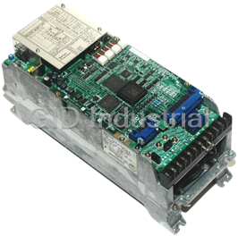


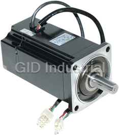


What they say about us
FANTASTIC RESOURCE
One of our top priorities is maintaining our business with precision, and we are constantly looking for affiliates that can help us achieve our goal. With the aid of GID Industrial, our obsolete product management has never been more efficient. They have been a great resource to our company, and have quickly become a go-to supplier on our list!
Bucher Emhart Glass
EXCELLENT SERVICE
With our strict fundamentals and high expectations, we were surprised when we came across GID Industrial and their competitive pricing. When we approached them with our issue, they were incredibly confident in being able to provide us with a seamless solution at the best price for us. GID Industrial quickly understood our needs and provided us with excellent service, as well as fully tested product to ensure what we received would be the right fit for our company.
Fuji
HARD TO FIND A BETTER PROVIDER
Our company provides services to aid in the manufacture of technological products, such as semiconductors and flat panel displays, and often searching for distributors of obsolete product we require can waste time and money. Finding GID Industrial proved to be a great asset to our company, with cost effective solutions and superior knowledge on all of their materials, it’d be hard to find a better provider of obsolete or hard to find products.
Applied Materials
CONSISTENTLY DELIVERS QUALITY SOLUTIONS
Over the years, the equipment used in our company becomes discontinued, but they’re still of great use to us and our customers. Once these products are no longer available through the manufacturer, finding a reliable, quick supplier is a necessity, and luckily for us, GID Industrial has provided the most trustworthy, quality solutions to our obsolete component needs.
Nidec Vamco
TERRIFIC RESOURCE
This company has been a terrific help to us (I work for Trican Well Service) in sourcing the Micron Ram Memory we needed for our Siemens computers. Great service! And great pricing! I know when the product is shipping and when it will arrive, all the way through the ordering process.
Trican Well Service
GO TO SOURCE
When I can't find an obsolete part, I first call GID and they'll come up with my parts every time. Great customer service and follow up as well. Scott emails me from time to time to touch base and see if we're having trouble finding something.....which is often with our 25 yr old equipment.
ConAgra Foods