

 Manufacturers
WARRICK CONTROLS 1F1D0
Description
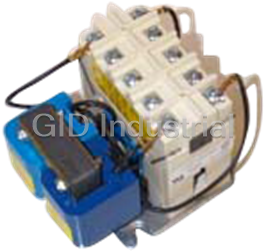
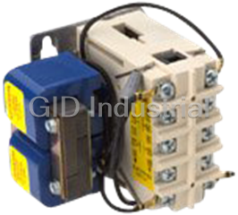
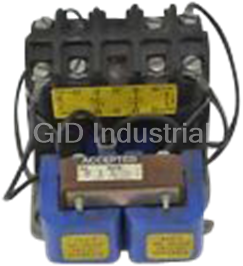
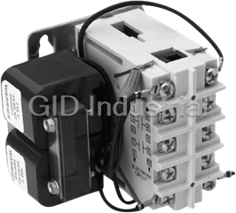
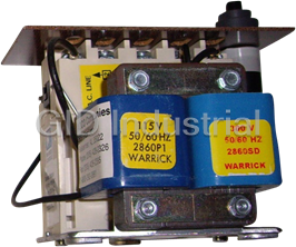
Warrick Controls 1F1D0 Electromechanical Control Relay, 3 N.O./0 N.C. Contact Configuration, 115 VAC Line Voltage, 300V Secondary / 7.0k Ohms @ 500 (Distance/Ft.), Open Enclosure Type.
Part Number
1F1D0
Price
Request Quote
Manufacturer
WARRICK CONTROLS
Lead Time
Request Quote
Category
Electromechanical Control Relay
Features
- 115 VAC Line Voltage
- 3 N.O./0 N.C. Contact Configuration
- 300V Secondary/7.0k Ohms @ 500 (Distance/Ft.)
- Open Enclosure Type.
Datasheet

Extracted Text
DIAGRAM F3 DIAGRAM F4 DIAGRAM F1 DIAGRAM F2 Form 70 LOW LEVEL LOCKOUT SERVICE HIGH LEVEL LOCKIN SERVICE SINGLE LEVEL SERVICE DIFFERENTIAL LEVEL SERVICE Sheet P/N 7800590 HIGH OR LOW LEVEL CUTOFF LOW LEVEL CUTOFF & ALARM HIGH LEVEL CUTOFF & ALARM PUMP DOWN ® Rev. E WITH MANUAL RESET WITH MANUAL RESET AND ALARM Warrick Series 1 To AC To AC To AC To AC Supply Supply Supply Supply Electromechanical Controls 2 1 2 1 2 1 2 1 Installation and Operation Bulletin To Load To Load To Load To Load 3 4 3 4 34 3 4 To Load To Load To Load To Load This bulletin should be used by experienced personnel as a guide to the installation of Series 1 controls. Selection or instal- N.O. 56 5 6 5 6 5 6 lation of equipment should always be accompanied by competent technical assistance. We encourage you to contact Gems To Load 7 8 7 8 7 8 7 8 Sensors or its representatives if further information is required. N.C. 10 9 10 9 10 9 9 10 Important: provide Ground Ground Important: provide jumper between Important: provide Ground Ground Reference Reference jumper between terminal pair 8-10. jumper between Reference Reference IMPORTANT! Electrode terminal pair 8-10. Electrode terminal pair 8-10. Electrode Electrode Before proceeding to install the control, Contact Operation: Load Contact Operation: Load contacts Contact Operation: Load contacts 3-4 Contact Operation: Load contacts 3-4 Read and thoroughly understand these instructions. contacts 3-4, 5-6 and 7-8 3-4 and 5-6 close when the level and 5-6 open when the level recedes and 5-6 close when the level rises to close when the level rises to rises to the short electrode below the electrode. They close when the electrode. They open when the the electrode. They open when connected to terminal 10. They open the level rises to the electrode and the level recedes below the electrode and when the level recedes below the normally open pushbutton switch is the level recedes below the the normally closed pushbutton switch electrode. electrode connected to terminal 7. momentarily actuated. is momentarily actuated. General DIAGRAM G3 DIAGRAM G4 DIAGRAM G1 DIAGRAM G2 HIGH LEVEL LOCKIN SERVICE LOW LEVEL LOCKOUT SERVICE SINGLE LEVEL SERVICE DIFFERENTIAL LEVEL SERVICE Temperature: -30 to +130°F ambient. HIGH LEVEL CUTOFF & ALARM Series 1 controls are simple, industrial type controls for LOW LEVEL CUTOFF & ALARM HIGH OR LOW LEVEL CUTOFF PUMP DOWN OR PUMP UP WITH MANUAL RESET WITH MANUAL RESET AND ALARM Terminals: #8 pan head screw with captivated wire clamping low sensitivity applications. They contain 2 or 3 pole To AC To AC To AC To AC plate. Maximum of 1 – #12 or 2 - #14 AWG prepared wires Supply Supply contacts with high contact ratings. The transformer/ Supply Supply relay combinations allow for multiple primary and second- per terminal. Use prepared conductors only, when wiring this 1 1 2 1 2 1 2 2 ary voltages. They are suitable for use in non-hazardous control. 1 To Load To Load To Load To Load locations with conductive liquids less than 20,000 Ohm/ 34 3 4 3 4 3 4 Time Delays: NONE cm specific resistance. To Load To Load To Load To Load N.0. Listings: Open Type – UL recognized, Enclosed 5 6 5 6 5 6 5 6 Type – UL Listed (File MP1430, Limit Control) To Load 7 8 7 8 7 8 7 8 Specifications CSA – Motor Control, Open or Enclosed N.C. 9 9 10 9 10 10 9 10 Important: provide Important: provide Important: provide Ground Ground Ground jumper between jumper between Control Design: Electrical-Mechanical level relay for use jumper between Ground Reference Reference Reference terminal pair 8-10. terminal pair 8-10. Reference terminal pair 8-10. Electrode with conductivity probes. Electrode Electrode Electrode Contact Design: 2 or 3 SPST (Non-Powered): Offered in Contact Operation: Load contact 3-4 Contact Operation: Load contact 3-4 Contact Operation: Load contact 3-4 Contact Operation: Load contact 3-4 both N.O. and N.C. - See contact configuration chart. closes and load contact 5-6 opens opens and load contact 5-6 closes opens and load contact 5-6 closes when opens and load contacts 5-6 and 7-8 when the level recedes below the when the level rises to the short the level rises to the electrode.Contact Contact Rating: 16A @ 115VAC; 8A @ 230VAC, 1H.P. electrode. Contact 3-4 opens and close when the level rises to the electrode connected to terminal 10. 3-4 closes and contact 5-6 opens when contact 5-6 closes when the level rises Contact 3-4 closes and contact 5-6 electrode. Contact 3-4 closes and the level recedes below the electrode @ 115 of 230 VAC to the electrode and the normally open opens when the level recedes below and the normally closed pushbutton contacts 5-6 and 7-8 opens when the pushbutton switch is momentarily the long electrode connected to switch is momentarily actuated. Supply Voltage: 24,115,230,460,575 nominal, plus level recedes below the electrode. actuated. terminal 7. 10%, minus 15%, 50/60 Hz. DIAGRAM H3 DIAGRAM H4 DIAGRAM H1 DIAGRAM H2 Supply Current: 115,230,460,575 VAC, Relay energized HIGH LEVEL LOCKIN SERVICE LOW LEVEL LOCKOUT SERVICE SINGLE LEVEL SERVICE DIFFERENTIAL LEVEL SERVICE HIGH LEVEL CUTOFF & ALARM LOW LEVEL CUTOFF & ALARM HIGH OR LOW LEVEL CUTOFF PUMP UP draws 15VA. WITH MANUAL RESET WITH MANUAL RESET AND ALARM To AC Secondary Voltage: 25,75,150,300,500 VAC RMS with To AC To AC To AC Supply Supply Supply Supply open circuit on probes. Secondary Current: 6VA with short circuited electrode 1 1 2 1 2 1 2 2 1 To Load circuit. To Load To Load To Load 4 3 4 4 3 4 3 3 Sensitivity: Models operate from 50 to 20,000 OHM To Load To Load To Load To Load N.0. 5 6 5 6 5 6 5 6 maximum specific resistance – Factory Set. To Load 7 8 7 8 7 8 7 8 N.C. Internal Wiring 9 10 9 10 9 10 Dimension diagram of open control 9 10 Important: provide Important: provide Important: provide Diagram Ground Ground Ground Ground jumper between jumper between 3 keyholes for #6 mounting screws jumper between Reference Reference Reference Reference terminal pair 8-10. terminal pair 8-10. terminal pair 8-10. Electrode Electrode Electrode Electrode 12 1 5/16” 3 4 Contact Operation: Load contacts 3-4 Contact Operation: Load contacts 3-4 Contact Operation: Load contacts 3-4 Contact Operation: Load contacts and 5-6 open when the level rises to and 5-6 open when the level rises to and 5-6 closes when the level recedes 3-4 and 5-6 open and contact 7-8 3 3/16” 5 6 the electrode. They close when the the short electrode connected to below the electrode. They open when closes when the level rises to the level recedes below the electrode and terminal 10. They close when the the level rises to the electrode and the electrode. Contact 3-4 and 5-6 close 1 5/16” 78 level recedes below the long normally open pushbutton switch is the normally closed pushbutton switch and contact 7-8 opens when the is momentarily actuated. electrode connected to terminal 7. momentarily actuated. level recedes below the electrode. 910 Gems Sensors Inc. 2 1/2” Contact Configuration One Cowles Road 4 1/4” 3 3/16” ‘G’ is shown Plainville, CT 06062-1198 Tel: 860-793-4579 Application Table Series 1 X X X X X Contacts^^ Wiring **Required Basic Service Function Diagram Electronics Symbol^ N.O. N.C. C1 C 2 0 High Level Alarm or Contact Configuration Secondary Voltage Enclosure Options AC Line Voltage 2 Low Level Cutoff 3 Letter # Letter Sec. Volts Sensitivity Dist/FT.* # Type Type F1 F 0 N.O. N.C. Voltage Letter A 25 50 75,000 C 2 0 1 115 VAC 0 OPEN A N.O. Reset Sw. High Level Cutoff or E1 E 0 2 B 75 NEMA 1 C N.C. Reset Sw. D 1 1 2 230 VAC 450 7,500 1 2 Single Level Low Level Alarm C 150 1.5K 1,750 NEMA 4 J 0 3 0 2 4 460 VAC 4 J1 E D 300 F 3 0 5 575 VAC 7.0K 500 D1 D 1 1 500 20.0K 2 1 6 115/230 VAC E 150 G High or Low Level 2 H 1 2 7 24 VAC G1 G 2 1 Cutoff or Alarm J 0 3 H1 H 1 2 * Distance based on 14 AWG wire type THHN or MTW C2 C 2* 0 Pump Down 3 3* F2 F 0 Note: For liquids of known specific resistance choose a sensitivity greater than and closest to that value in ohm/cm. Differential D D2 1* 1 Pump Up 3 Level H2 H 1* 2 Pump Down or Pump Up G2 1 3 G 2* D 1* 1 D3 Low Level Alarm with 2 Dashed Lines Represent Field Wiring 1* Manual Reset H3 H 2 DIAGRAM C2 DIAGRAM C3 DIAGRAM C1 DIAGRAM C4 C3 C 2* 0 Low Level Low Level Cutoff with DIFFERENTIAL LEVEL SERVICE SINGLE LEVEL SERVICE LOW LEVEL LOCKOUT SERVICE LOW HIGH LEVEL LOCKIN SERVICE 2 Lockout HIGH OR LOW LEVEL CUTOFF PUMP DOWN LEVEL CUTOFF & ALARM Manual Reset F 3* HIGH LEVEL CUTOFF & ALARM F3 0 WITH MANUAL RESET WITH MANUAL RESET AND ALARM Low Level Cutoff and 2 G3 G 2* 1 To AC To AC To AC To AC Alarm with Manual Reset Supply Supply Supply Supply C4 C 2* 0 High Level Alarm with 2 1 12 12 1 2 2 Manual Reset F4 F 3* 0 To Load To Load To Load To Load 3 4 3 4 3 4 3 4 D 1* High Level D4 1 High Level Cutoff with 2 N.O. Lockout Manual Reset H4 1* 2 H 5 6 5 6 5 6 5 6 To Load High Level Cutoff and 2* 2 G4 G 1 7 8 7 8 7 8 7 8 Alarm with Manual Reset N.C. 9 10 9 9 10 9 10 10 * One normally open contact required to seal electrode circuit. Number of normally open contacts available for Important: provide Important: provide Important: provide Ground Ground Ground jumper between Ground jumper between load duty therefore one less than figure indicated. jumper between Reference Reference Reference terminal pair 8-10. Reference terminal pair 8-10. terminal pair 8-10. Electrode Electrode Electrode ** Terminal 9 of control assumed connected to a reference electrode. Terminal 9 may be grounded to the vessel Electrode if the vessel is mettalic. ^ Letters represent 2nd place symbol in the component number of the control. Contact Operation: Load Contact Operation: Load contact Contact Operation: Load contact 3-4 Contact Operation: Load contact 3-4 ^^ All contacts available for load duty unless otherwise indicated by footnote. contacts 3-4 and 7-8 close 3-4 close when the level rises to opens when the level recedes below closes when the level rises to the when the level rises to the the short electrode connected to the electrode. It closes when the electrode. It opens when the level Mounting and Wiring Instructions electrode. They open when terminal 10. It opens when the level rises to the electrode and the recedes below the electrode and the the level recedes below the level recedes below the electrode normally open pushbutton switch is normally closed pushbutton switch is The Series 1 control may be wired in various ways. Select the wiring diagram, on pages 3 and 4, that matches the contact configura- electrode. connected to terminal 7. momentarily actuated. momentarily actuated. tion of your model number and your application. The Application Table on this page can assist you in determining which wiring diagram to use. DIAGRAM D3 DIAGRAM D4 DIAGRAM D1 DIAGRAM D2 LOW LEVEL LOCKOUT SERVICE HIGH LEVEL LOCKIN SERVICE SINGLE LEVEL SERVICE HIGH OR LOW DIFFERENTIAL LEVEL SERVICE LOW LEVEL CUTOFF & ALARM HIGH LEVEL CUTOFF & ALARM The Series 1 control must be mounted on a vertical surface with the transformer on the left-hand side. The control should be LEVEL CUTOFF AND ALARM PUMP UP WITH MANUAL RESET WITH MANUAL RESET mounted in an enclosure of proper Nema integrity and wired following N.E.C. and local codes. Terminals on the control are num- To AC To AC To AC To AC bered and are in the same relative position as the terminals shown in the wiring diagrams. Supply Supply Supply Supply 1 Each control has a data label on the right hand side of the terminal block. Terminal pair 1-2 must be continuously energized from an 1 1 2 1 2 1 2 2 AC supply line of the same electrical characteristics as shown on the data label. Each dry contact used for load duty must be wired To Load To Load To Load To Load 3 4 3 4 in series with the load, and that series branch connected across a power source compatible with the load. 34 34 N.0. 5 5 6 5 6 5 6 6 Grounding: To Load Series 1 controls mounted in an enclosure have a grounding terminal and wires provided for adequate grounding of the control and 8 7 8 7 8 7 8 7 N.C. conduit entrances to any external metal parts that may become energized. Conduit connections on fiberglass enclosures must be 9 9 10 9 10 10 9 10 connected via the green ground wire provided for in the enclosure. Caution: Bonding between conduits must be made. Important: provide Ground Ground Important: provide Important: provide Ground Ground jumper between Reference Reference jumper between jumper between Reference Reference Wiring must be provided to the electrodes as shown. Terminal 9 is a reference electrode termination and may be grounded to the terminal pair 8-10. Electrode Electrode terminal pair 8-10. terminal pair 8-10. Electrode Electrode vessel if the vessel is metallic. When the vessel is non-metallic, terminal 9 must be connected to an additional electrode of a length equal to, or longer than, the longest electrode used in the vessel. If the electrode fitting used has a metallic body and is supported Contact Operation: Load contact Contact Operation: Load contact Contact Operation: Load contact 3-4 directly upon a metallic vessel, the ground reference connection is facilitated by securing that end of the reference conductor beneath Contact Operation: Load contact 3-4 opens when the level rises to 3-4 closes when the level recedes opens when the level rises to the 3-4 opens and load contact 7-8 the head of one of the four screws which fasten the terminal housing to the body of the fitting. The jumper between terminal pair 8- the short electrode connected to below the electrode. It opens when electrode. It closes when the level closes when the level rises to the 10 and the pushbutton switch wiring on diagrams X2, X3 and X4 are required field connections. terminal 10. It closes when the the level rises to the electrode and recedes below the electrode and the electrode. Contact 3-4 closes and level recedes below the long the normally open pushbutton normally closed pushbutton switch contact 7-8 opens when the level electrode connected to terminal 7. switch is momentarily actuated. is momentarily actuated. recedes below the electrode. The control-to-fitting wire distance should not exceed those listed in the secondary voltage chart located on page 3.
Frequently asked questions
How does Industrial Trading differ from its competitors?

Is there a warranty for the 1F1D0?
Which carrier will Industrial Trading use to ship my parts?
Can I buy parts from Industrial Trading if I am outside the USA?
Which payment methods does Industrial Trading accept?


What they say about us
FANTASTIC RESOURCE
One of our top priorities is maintaining our business with precision, and we are constantly looking for affiliates that can help us achieve our goal. With the aid of GID Industrial, our obsolete product management has never been more efficient. They have been a great resource to our company, and have quickly become a go-to supplier on our list!
Bucher Emhart Glass
EXCELLENT SERVICE
With our strict fundamentals and high expectations, we were surprised when we came across GID Industrial and their competitive pricing. When we approached them with our issue, they were incredibly confident in being able to provide us with a seamless solution at the best price for us. GID Industrial quickly understood our needs and provided us with excellent service, as well as fully tested product to ensure what we received would be the right fit for our company.
Fuji
HARD TO FIND A BETTER PROVIDER
Our company provides services to aid in the manufacture of technological products, such as semiconductors and flat panel displays, and often searching for distributors of obsolete product we require can waste time and money. Finding GID Industrial proved to be a great asset to our company, with cost effective solutions and superior knowledge on all of their materials, it’d be hard to find a better provider of obsolete or hard to find products.
Applied Materials
CONSISTENTLY DELIVERS QUALITY SOLUTIONS
Over the years, the equipment used in our company becomes discontinued, but they’re still of great use to us and our customers. Once these products are no longer available through the manufacturer, finding a reliable, quick supplier is a necessity, and luckily for us, GID Industrial has provided the most trustworthy, quality solutions to our obsolete component needs.
Nidec Vamco
TERRIFIC RESOURCE
This company has been a terrific help to us (I work for Trican Well Service) in sourcing the Micron Ram Memory we needed for our Siemens computers. Great service! And great pricing! I know when the product is shipping and when it will arrive, all the way through the ordering process.
Trican Well Service
GO TO SOURCE
When I can't find an obsolete part, I first call GID and they'll come up with my parts every time. Great customer service and follow up as well. Scott emails me from time to time to touch base and see if we're having trouble finding something.....which is often with our 25 yr old equipment.
ConAgra Foods