

 Manufacturers
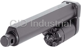
WARNER ELECTRIC S24-17A8-02
Description
Warner Electric S24-17A8-02 Linear Actuator. 24 VDC | 2" Stroke | 75 lb load capacity
Part Number
S24-17A8-02
Price
Request Quote
Manufacturer
WARNER ELECTRIC
Lead Time
Request Quote
Category
Linear Actuator
Specifications
Duty Cycle At Full Load
25%
Input Voltage
24 Vdc
Limit Switches
fixed
Load Capacity
75
Stroke Length
2.000
Type Of Screw
acme
Features
- 2" Stroke
- 24 VDC
- 75 lb load capacity
Datasheet

Extracted Text
Industrial Linear Actuators * ©2003 Danaher Motion. Printed in the U.S.A. The specifications in this publication are believed to be accurate and reliable. However, it is the responsibility of the product user to determine the suitability of Thomson products for a specific application. D-1 While defective products will be replaced without charge if promptly returned, no liability is assumed beyond such replacement. * Trademark of Danaher Motion. DANAHER MOTION is registered in the U.S. Patent and Trademark Office and in other countries. Phone: 1-800-554-8466 Overview Website: www.linearactuators.com Thomson Electrak and Performance Pak Industrial Linear Actuators Danaher Motion pioneered the development of Thomson ball screw actuators for NC machine tools and jet aircraft landing gears, wing flap control, wing sweeps, thrust reversers….all the way to the docking platform and manipulator arm on the space shuttle. The first generation of general purpose actuators were developed for remote push button control of accessory drives on garden tractors and automated farm equipment. The Industrial Actuators presented in this catalog represent proven design concepts that you’ll find in the entire Electrak and PPA series. From light load E-050s to the high performance Electrak 205, capable of handling loads in excess of 1000 lbs, and 10 times the life of other available actuators. We have brought together the combined offering of the clevis to clevis mount Electrak series, and the trunnion mount PPA units, to represent the most versatile selection of industrial actuators available. Thomson Industrial Actuators….rugged, reliable remote linear motion control with the push of a button. Features and Benefits: Easy Wiring Control leads are safely and easily wired. See specific model descriptions for details. Compact Design An Electrak actuator with a four inch stroke length can produce 1500* pounds of force from a 12" package. Electrak 1 series actuators fit small areas with package lengths as short as six inches. Maintenance-free Since all adjustments and lubrication are made during assembly, no maintenance is required or recommended. Consistent, repeatable performance is provided for the entire lifetime of the actuator. Bidirectional Electrak and PPA actuators can push and pull loads ranging from one pound to 3/4* of a ton, and can extend up to 36 inches. With MCS-2000 series controls, you can create the actuator control system to meet your particular motion control requirements.. Rugged and reliable Electrak actuators incorporate strong, high quality components to assure trouble-free service. Rugged spur gearing, aircraft quality lubricants and high performance motors provide the maximum life and value for the user. Gasketed and sealed throughout for maximum protection. Stainless steel or aluminum extension tubes prevent corrosion. Cover tube stiffeners increase load support. Thermal overload switch protects motors. Versatile Motors used on Electrak and PPA actuators utilize thermal switches in their windings to shut the actuator off in case of overheating. Reset is automatic after the motor has cooled. A standard overload clutch automatically ratchets if the load is too great or at the end of a stroke. Again, reset is automatic upon load reduction or direction reversal. With their compact size, Electrak actuators can be located in confined areas, yet will move loads from 25 to 1500* pounds. Linear actuators will hold their loads with no power draw. Stroke lengths of 1 to 36 inches are available and speeds are as high as two inches per second. Weatherproofing makes these actuators ideal for use on outdoor equipment. Actuators are easy to apply and easy to install and offer advantages over mechanical and hydraulic systems in many linear motion applications. They are self-contained, rugged, and durable, making them ideal for almost any lift, push, or pull application. Easy Installation Actuators are quickly and easily mounted by several methods and require only 2 wires for operation. * Consult applications for loads above 1000 lb. * ©2003 Danaher Motion. Printed in the U.S.A. The specifications in this publication are believed to be accurate and reliable. However, it is the responsibility of the product user to determine the suitability of Thomson products for a specific application. D-2 While defective products will be replaced without charge if promptly returned, no liability is assumed beyond such replacement. * Trademark of Danaher Motion. DANAHER MOTION is registered in the U.S. Patent and Trademark Office and in other countries. Phone: 1-800-554-8466 Website: www.linearactuators.com Overview Industrial Linear Actuator Applications Industrial Linear Actuators provide a wide range of applications... Adjusting A single PPA actuator coupled with linkages will accommodate all the requires positions of a motorized hospital bed. Transmission shift Actuators provide “shift by wire” instead of cumbersome mechanical linkages, binding cables or messy hydraulics. Feedback, built into the actuator, can be used to make multiple step points or shift positions. Floor Sweeper/Scrubber Electrak actuators apply the downforce on the squeegee to pick up the water during cleaning. Barrier and Swing gates Electrak self-contained, weather- proof actuators improve the reliability of various gate styles by replacing complex operating mechanisms. No separate motor, gearbox, belt, limit switches, belts or chains to slip or break. Automatic operation of dispensing values are easily accomplished with reliable, repeatable, electro-mechanical linear actuators. Positioning The PPA actuator combines all-weather design and dependability for trouble-free actuation of residential and commercial satellite dishes. Sprayer booms and heads The load limiting clutch prevents damage to the actuator or equipment when extending or retracting the spray booms. Sprayer nozzles can be precisely positioned. * ©2003 Danaher Motion. Printed in the U.S.A. The specifications in this publication are believed to be accurate and reliable. However, it is the responsibility of the product user to determine the suitability of Thomson products for a specific application. D-3 While defective products will be replaced without charge if promptly returned, no liability is assumed beyond such replacement. * Trademark of Danaher Motion. DANAHER MOTION is registered in the U.S. Patent and Trademark Office and in other countries. Phone: 1-800-554-8466 Product Selection Website: www.linearactuators.com Quick Reference Guide Electrak Electrak E150 Electrak 1 Electrak 5 Electrak 2 E050/Q050 Input 12, 24, 36 VDC, 12VDC 12VDC 12VDC 12 VDC 115VAC Voltage 12, 24 VDC 115 VAC 24VDC 24VDC 24VDC 230VAC Load 25, 110, 25 25 25 500 Capacity (lbs.) 50, 112 225, 450 75 75 75 250 1000, 1500* Stroke Length 1, 2, 4, 6, 8, 4, 8, 12 4, 8, 12, (inches) 2, 4, 6, 8 10, 12, 14, 16 2, 4, 6 2, 4, 6 2, 4, 6 18*, 24* 18, 24 Type of Acme Acme Acme Acme Acme Acme Ball Lead Screw screw screw screw screw screw screw screw Duty Cycle at Full Load 25% 25% 25% 25% 25% 25% 25% Load Limiting Clutch Yes No No No No Yes Yes Limit Fixed end of Optional adjustable Only with Switches Stroke Standard end of stroke Fixed MCS-2007 control Fixed No No Feedback Optional Potentiometer Optional Potentiometer No Potentiometer No No No Motor Overload Protection Yes Yes Yes Yes Yes Yes Yes Restraining None - None - Torque (max) internally restrained internally restrained 20 lb. in. 20 lb.in. 20 lb.in 100 lb. in. 100 lb. in. Environment IP56 IP56 Washdown Washdown Washdown Washdown Oily, damp, dirty 96 hour 96 hour 96 hour 96 hour Outdoors with drip salt spray salt spray salt spray salt spray shield over motor & proper grounding & ground fault protection Standard Control DE14-1E DF14-1F MCS-2005 (115VAC) MCS-2007 (115VAC) MCS-2005 (115VAC) 6932-101-054 MCS-2041 (115VAC) - controls 1 actuator - controls 1 actuator MCS-2006 (230VAC) MCS-2008 (230VAC) MCS-2006 (230VAC) MCS-2042 (230VAC) Optional Control(s) DE14-2E DF14-2F MCS-2015 Relay Supplied - controls 2 actuators - controls 2 actuators MCS-2025 by Customer Catalog Page D-8 D-12 D-14 D-14 D-14 D-18 D-20 * ©2003 Danaher Motion. Printed in the U.S.A. The specifications in this publication are believed to be accurate and reliable. However, it is the responsibility of the product user to determine the suitability of Thomson products for a specific application. D-4 While defective products will be replaced without charge if promptly returned, no liability is assumed beyond such replacement. * Trademark of Danaher Motion. DANAHER MOTION is registered in the U.S. Patent and Trademark Office and in other countries. Phone: 1-800-554-8466 Website: www.linearactuators.com Product Selection Quick Reference Guide Special Purpose Actuators Performance Pak Performance Pak Electrak 100 Electrak 205 T-90 T-130 Electrak 10 MovoAct Actuators (DC) Actuators (AC) 12VDC 115VAC 12,24,36,90 VDC 110,220 VAC Dependant on motor/ Dependant on motor/ 12, 24VDC 24VDC 24VDC 230VAC control selected control selected 115, 230VAC 500 500 500 750 500 1000, 1500* 1000, 1500* 1000, 1500* 1500 1500 2250 9000 1000 4, 8, 12, 4, 8, 12, 4, 8, 12 4, 8, 12 4, 8, 12 18*, 24* 18, 24 18, 24 18, 24, 36 18, 24, 36 59 78 4,8,12,18,24 Ball Ball Ball Ball Ball Ball Ball Acme or Ball screw screw screw screw screw screw screw screw 25% 25% 25% 30% 30% 100% 100% 25% Yes Yes No Yes Yes No No Yes No Adjustable Adjustable Optional Optional Optional Optional Optional No Potentiometer Potentiometer Optional Optional Optional Optional Optional Yes Yes Yes Yes Yes No No Yes 100 lb. in. 100 lb. in. 100 lb. in. 100 lb. in. 100 lb. in. N/A N/A N/A Washdown Washdown Oily, damp, dirty. 96 hour 96 hour Outdoors with drip salt spray _ _ salt spray shield over motor & proper grounding _ _ Indoor & ground fault protection MCS-2025 MCS-2035 MCS-2051 (115VAC) P/N 7820406 MCS-2052 (230VAC) 110VAC in 90 VDC out Variable Speed DF14-1F for 90 VDC Units _ _ _ MCS-2015 Only MCS-2041 MCS-2015 MCS-2015MCS-20 D-22 D-24 D-26 D-30 D-35 D-41 D-42 D-43 * ©2003 Danaher Motion. Printed in the U.S.A. The specifications in this publication are believed to be accurate and reliable. However, it is the responsibility of the product user to determine the suitability of Thomson products for a specific application. D-5 While defective products will be replaced without charge if promptly returned, no liability is assumed beyond such replacement. * Trademark of Danaher Motion. DANAHER MOTION is registered in the U.S. Patent and Trademark Office and in other countries. Phone: 1-800-554-8466 Website: www.linearactuators.com Application Analysis Worksheet Industrial Linear Actuators Application Analysis Worksheet For selection assistance, fax to your local Danaher Motion distributor or Danaher Motion at 1-800-445-0329. Date ___________________________________________________________________________________________________ Company ________________________________________________________________________________________________ Address _________________________________________________________________________________________________ City ______________________________________________ State_________________________ ZipCode _________________ Name __________________________________________________________________________________________________ Title _________________________ Phone (___) __________________ Fax (___) ______________________ Basic Application Load _________ lbs. Side Load _________ lbs. Speed _________ inches per second Duty Cycle _________ % of time running versus time still Stroke length _________ inches Life _________ inches or cycles Environmental � Clean � Damp � Oil splash � Outdoors Power available _________ VAC _________ VDC Quantity _________ Please use the worksheet to the right for drawings and additional information.. * ©2003 Danaher Motion. Printed in the U.S.A. The specifications in this publication are believed to be accurate and reliable. However, it is the responsibility of the product user to determine the suitability of Thomson products for a specific application. D-6 While defective products will be replaced without charge if promptly returned, no liability is assumed beyond such replacement. * Trademark of Danaher Motion. DANAHER MOTION is registered in the U.S. Patent and Trademark Office and in other countries. Phone: 1-800-554-8466 Website: www.linearactuators.com Worksheet NOTES: * ©2003 Danaher Motion. Printed in the U.S.A. The specifications in this publication are believed to be accurate and reliable. However, it is the responsibility of the product user to determine the suitability of Thomson products for a specific application. D-7 While defective products will be replaced without charge if promptly returned, no liability is assumed beyond such replacement. * Trademark of Danaher Motion. DANAHER MOTION is registered in the U.S. Patent and Trademark Office and in other countries. Phone: 1-800-554-8466 Electrak E050 Website: www.linearactuators.com 12 and 24 VDC 30, 60, 112 lb. load capacities Features • Short retracted length • Low cost • Quiet operation • IP-56 rated for outdoor use • Durable, lightweight, corrosion resistant plastic housing • Available DC voltages: 12 or 24 • Estimated life at rated load is 40,000 cycles minimum Compact, low cost plastic housing The Electrak E050 actuator is the new compact, quiet, low priced actuator Typical applications suitable for a variety of markets and applications. This feature packed • Raising and lowering leg supports on actuator has a very short retracted length for applications where space is powered wheelchairs a premium: • Boat seat back adjustment • Squeegee lift on floor cleaner • It is designed to be quiet for medical or office applications. • Throttle control on salt spreader • It has built in limit switches for end of stroke protection and a clutch for mid stroke protection. • Positioning/hiding stereo speakers in autos • Air valves/damper controls • The colors are molded into the plastic to both eliminate the need for paint and touchup of scratches. • Special effects on commercial video games • The actuator has a breather tube in the wiring harness to allow the • Jet ski trim actuator actuator to operate without drawing water through the seals on the cover tube. Controls • It is available with a control and pendant for one or two actuators. DE14 series actuator controls operate Thomson E050 actuators. Available with one or two 24 VDC outputs, the DE14 has The entire actuator has been designed for ease of installation, light weight, a handset to manually control bi-directional motion on each of its quiet operation, no maintenance and low cost. control outputs independently. For details see page D-47. Dimensions Stroke AA Length AA with potentiometer 2" (50) 5.5 (140) 6.75 (172) 4" (100) 7.5 (191) 8.75 (222) 6" (150) 9.5 (242) 10.75 (273) 8" (200) 11.5 (292) Dimensions are for standard units Crossholes shown standard M3 mount = 90˚ rotated * ©2003 Danaher Motion. Printed in the U.S.A. The specifications in this publication are believed to be accurate and reliable. However, it is the responsibility of the product user to determine the suitability of Thomson products for a specific application. D-8 While defective products will be replaced without charge if promptly returned, no liability is assumed beyond such replacement. * Trademark of Danaher Motion. DANAHER MOTION is registered in the U.S. Patent and Trademark Office and in other countries. Phone: 1-800-554-8466 Website: www.linearactuators.com Electrak E050 Specifications DE12-17W41-XX DE12-17W42-XX DE12-17W44-XX Dynamic load 112 lbs. max. 60 lbs. max. 30 lbs. max. Static Load 224 lbs. max. 120 lbs. max. 60 lbs. max. Speed .48"/sec @ no load .95"/sec @ no load 1.9"/sec @ no load .37"/sec @ 112 lbs. .72"/sec @ 60 lbs. 1.45"/sec @ 30 lbs. End play 0.060" max less clevis 0.060" max less clevis 0.060" max less clevis Restraining torque Restrained internally Input voltage 12 or 24 VDC Amperage (12 VDC) 3.8 amp max. at rated dynamic load End of stroke Fixed limit switches Mid stroke protection Load limiting clutch Thermal protection Internal motor breaker Lead wires 18 AWG PVC 800 Connectors Packard Electric Pack-Con Power switch Optional DPDT Temperature -30˚ to +180˚ F (-34˚ to 82˚ C) Environment 12 or 24 VDC Duty cycle 25% @ rated load and @ 70˚ F Anti-rotation Tube can rotate max. of 7˚ Performance Curves DEXX-17W41 DEXX-17W42 DEXX-17W44 DE 12 Motor Curve Input voltage: 10-16 volts Nominal performance at 12 VDC and 70°F (21°C) Amperage: 3.8 amps max. at rated dynamic load and 70°F (21°C) ambient DE 24 Motor Curve Input voltage: 20–28 volts Nominal performance at 24 VDC and 70°F (21°C) Amperage: 1.9 amps max. at rated dynamic load and 70°F (21°C) ambient How To Order DEXX-17W4X-XXXXXXX Motor Type: D = DC Other Options: N = None, W = White Housing Actuator Type: E = E050 Front Mounting: H = Crosshole Motor Voltage: 12 or 24 Rear Mounting: H = Crossholes are shown above, M = M3, rotated 90° – =OEM Version; D=Distributor Version Feedback: N = None, P = Potentiometer Gear Ratio: 17:1 Limit Switches: F = Fixed Limits Screw Type: W = Worm Screw Diameter: (tenths of an inch) Screw Lead: (tenths of an inch) 1,2,4 Stroke Length: Inches Example: DE12-17W41-04FNHHN * ©2003 Danaher Motion. Printed in the U.S.A. The specifications in this publication are believed to be accurate and reliable. However, it is the responsibility of the product user to determine the suitability of Thomson products for a specific application. D-9 While defective products will be replaced without charge if promptly returned, no liability is assumed beyond such replacement. * Trademark of Danaher Motion. DANAHER MOTION is registered in the U.S. Patent and Trademark Office and in other countries. Phone: 1-800-554-8466 Website: www.linearactuators.com Electrak Q050 12 and 24 VDC 30, 60, 112 lb. load capacities Features • Short retracted length • Low cost • Quiet operation • IP-51 rating standard • Durable, lightweight, corrosion resistant plastic housing • Available for 12 or 24 VDC input • Estimated life at rated load is 40,000 cycles minimum Trouble-free, • Optional IP-56 sealing reliable motion control The Electrak Q050 actuator is the new compact, ultra-quiet low priced actuator specifically designed for office, healthcare or consumer applications. This feature-packed actuator can be ordered with a hand held pendant control to make installation and operation plug and play. Controls • Designed to be quiet for medical or office applications. DE14 series actuator controls operate Thomson Q050 actuators. • Built in limit switches for end of stroke protection. Available with one or two 24 VDC outputs, the DE14 has a handset • Built in overload clutch for mid-stroke stall protection. to manually control bi-directional motion on each of its control outputs independently. See page D-47. • Short retracted length for applications where space is a premium. • Color molded into the plastic housing to eliminate the need for paint and for touch up of scratches. • Available with control and hand held pendant for one or two actuators. The entire actuator and control has been designed for ease of installation, quiet operation, no maintenance and low cost. Dimensions Stroke Length “AA” “AA” With Potentiometer 2" 5.5 6.75 4" 7.5 8.75 6" 9.5 10.75 8" 11.5 – Dimensions are for standard units. Crossholes shown std. M3 mount=90˚ rotated * ©2003 Danaher Motion. Printed in the U.S.A. The specifications in this publication are believed to be accurate and reliable. However, it is the responsibility of the product user to determine the suitability of Thomson products for a specific application. D-10 While defective products will be replaced without charge if promptly returned, no liability is assumed beyond such replacement. * Trademark of Danaher Motion. DANAHER MOTION is registered in the U.S. Patent and Trademark Office and in other countries. Phone: 1-800-554-8466 Website: www.linearactuators.com Electrak Q050 Specifications DE12Q17W41-XX DE12Q17W42-XX DE12Q17W44-XX Dynamic load 112 lbs. max. 60 lbs. max. 30 lbs. max. Static Load 224 lbs. max. 120 lbs. max. 60 lbs. max. Speed .36"/sec @ no load .70"/sec @ no load 1.5"/sec @ no load .30"/sec @ 112 lbs. .55"/sec @ 60 lbs. 1.2"/sec @ 30 lbs. End play 0.060" max less clevis 0.060" max less clevis 0.060" max less clevis Restraining torque Restrained internally Input voltage 12 or 24 VDC Amperage (12 VDC) 2.5 amp max. at rated dynamic load End of stroke Fixed limit switches Mid stroke protection Load limiting clutch Thermal protection Internal motor breaker Lead wires 18 AWG PVC 800 Connectors Packard Electric Pack-Con Power switch Optional DPDT Temperature -30˚ to +180˚ F (-34˚ to 82˚ C) Environment IP-51 standard Duty cycle 25% @ rated load and @ 70˚ F Anti-rotation Tube can rotate max. of 7˚ Performance Curves DEXXQ17W44 DEXXQ17W41 DEXXQ17W42 DE12Q Motor Curve Input voltage: 10–16 volts Nominal performance at 12 VDC and 70°F (21°C) Amperage: 2.5 amps max. at rated dynamic load and 70°F (21°C) ambient DE24Q Motor Curve Input voltage: 20–28 volts Nominal performance at 24 VDC and 70°F (21°C) Amperage: 1.2 amps max. at rated dynamic load and 70°F (21°C) ambient Customer Special** How To Order and Drawing Ref. No. **If actuator is a customer special then the 15th and 16th characters are DEXXQ17W4X-XXXXXXW always numeric (drawing ref.) instead of alpha. The last 2 characters are alpha for customer identification. Motor Type: D = DC Actuator Type: E = 050 Example: DE12Q17W41-04FNHHW Motor Voltage: 12 or 24 Other Options: N = None, W = White Housing Version: Q = Q050 Front Mtg.: H = Crosshole Gear Ratio: 17:1 Rear Mtg.: H = Crossholes are shown above, Screw Type: W = Worm M3 = Rotated 90° Screw Diameter (tenths of an inch) Feedback: N = None, P = Potentiometer Screw Lead (tenths of an inch) 1,2,4 Limit Switches: F = Fixed Limits Stroke Length: Inches * ©2003 Danaher Motion. Printed in the U.S.A. The specifications in this publication are believed to be accurate and reliable. However, it is the responsibility of the product user to determine the suitability of Thomson products for a specific application. D-11 While defective products will be replaced without charge if promptly returned, no liability is assumed beyond such replacement. * Trademark of Danaher Motion. DANAHER MOTION is registered in the U.S. Patent and Trademark Office and in other countries. Phone: 1-800-554-8466 Website: www.linearactuators.com Electrak E150 12 and 24 VDC 110, 225, 450 lb. load capacities Features • Low cost • Quiet operation • Optional adjustable limit switches • IP-56 rated for outdoor use • Durable, lightweight, plastic housing • Available DC voltages: 12 or 24 • Estimated life at rated load is 40,000 cycles minimum Compact, low cost plastic housing Typical applications The Electrak 150 is the first of a new series of low priced, quiet actuators • Automatic security gate positioning with different load and speed ranges. • Raise/lower the deck on riding mowers There are a number of design features that make this actuator different. The • Position ladders, vents, discharge chutes on combines optional limit switches are designed to operate with fewer parts. The plastic • Tilt/recline on powered wheelchairs cover is designed to be recyclable. The actuator has a breather tube in the wiring harness to allow the actuator to operate without drawing water • Position ergonomic tables, chairs through the seals on the cover tube. The colors are molded into the plastic to • Position diverters on conveyors both eliminate the need for paint and touchup of scratches. The anodized • Position jigs in flexible assembly operations aluminum cover tube is corrosion resistant and also hides scratches. The extension tube is stainless steel and the front and rear adapters are zinc die castings for corrosion resistance. All of the thrust is resolved through the Controls screw with the plastic housing providing environmental protection but DF14 controls operate one or two Electrak 150 actuators. Available carrying no load. The entire actuator has been created for ease of installation, with one or two 24 VDC outputs with a handset to manually control quiet operation, no maintenance, light weight, and low cost. bi-directional motion on each of the control outputs. Each actuator can be operated independently and sequentially but not simultane- ously. It has quick disconnect sockets for the handset, cable adapters for 5, 10 and 15 foot lengths to connect to each actuator. See page D-47. Dimensions AA Stroke Mechanical retracted length Electrical Pot and Wt. Length No Feedback (NN) Pot only Limit Limit lbs. 10W51 10W52 (NP) Switches Switches 10W54 (LN) (LP) 1" 7.51 (191) 7.56 (192) 8.51 (216) 9.01 (229) 9.01 (229) 4.79 2" 8.51 (216) 8.56 (217) 9.51 (244) 10.01 (254) 10.01 (254) 4.89 4" 10.51 (267) 10.56 (268) 11.51 (292) 12.01 (305) 12.01 (305) 5.18 6" 12.51 (318) 12.56 (319) 13.51 (343) 14.01 (356) 14.01 (356) 5.46 8" 14.51 (369) 14.56 (370) 15.51 (394) 16.01 (407) 16.01 (407) 5.75 Dimensions are for standard units. 10" 16.51 (419) 16.56 (421) 17.51 (445) 18.01 (458) 18.01 (458) 6.03 12" 18.51 (470) 18.56 (471) 19.51 (496) 20.01 (508) 20.01 (508) 6.32 14" 20.51 (521) 20.56 (522) 21.51 (546) 22.01 (559) 22.01 (559) 6.60 16" 22.51 (572) 22.56 (573) N/A 24.01 (610) N/A 6.88 ©2003 Danaher Motion. Printed in the U.S.A. The specifications in this publication are believed to be accurate and reliable. * However, it is the responsibility of the product user to determine the suitability of Thomson products for a specific application. D-12 While defective products will be replaced without charge if promptly returned, no liability is assumed beyond such replacement. * Trademark of Danaher Motion. DANAHER MOTION is registered in the U.S. Patent and Trademark Office and in other countries. Phone: 1-800-554-8466 Website: www.linearactuators.com Electrak E150 Specifications DF12-10W51-XXX DF12-10W52-XXX DF12-10W54-XX Dynamic load 450 lbs. max. 225 lbs. max. 110 lbs. max. Static Load 900 lbs. max. 400 lbs. max. 330 lbs. max. Speed .75"/sec @ no load 1.40"/sec @ no load 2.8"/sec @ no load .4"/sec @ 450 lbs. .8"/sec @ 225 lbs. 1.6"/sec @ 110 lbs. End play 0.036" max less clevis 0.036" max less clevis 0.046" max less clevis Restraining torque Restrained internally Input voltage 12, 24 VDC (36 VDC*, 115 VAC*) Amperage (12 VDC) 2.5-13 (50 amp @ stall) End of stroke Stall, optional limit switches Thermal protection Internal motor breaker Lead wires 16 AWG PVC 800 Connectors Packard Electric Pack-Con Power switch Optional DPDT Temperature -30˚ to +150˚ F (-34˚ to 66˚ C) Environment IP-56 outdoor use Duty cycle 25% @ 70˚ F Anti-rotation Tube can rotate max. of 7˚ * consult customer service Performance Curves DF 12 Motor Curve DFXX-10W51 DFXX-10W52 DFXX-10W54 Input voltage: 10–16 volts Nominal performance at 12 VDC and 70°F (21°C) Amperage: 13 amps max. at rated dynamic load and 70°F (21°C) ambient Max. amp draw at stall: 50 amps DF 24 Motor Curve Input voltage: 20–28 volts Nominal performance at 24 VDC and 70°F (21°C) Amperage: 6.5 amps max. at rated dynamic load and 70°F (21°C) ambient Max. amp draw at stall: 25 amps How To Order DFXX-10W5X-XXXXXXX Motor Type: D = DC Other Options: N = None Actuator Type: F = E150 Front Mounting: H = Crosshole Motor Voltage: 12, 24, 36 Rear Mounting: H = Crossholes are shown above, M = Both front and rear rotated 90° Feedback: N = None, P = Potentiometer Gear Ratio: 10:1 Limit Switches: L = Limits, N = None Screw Type: W = Worm Screw Diameter: (tenths of an inch) Screw Lead: (tenths of an inch) 1,2,4 Stroke Length: Inches Example: DF12-10W51-04LNHHN DANAHER MOTION is a trademark. * Danaher Motion makes every attempt to ensure accuracy and reliability of the specifications in this publication. Specifications are subject to change without notice. Danaher Motion provides this information "AS IS" and disclaims all warranties, express or implied, including, but not limited to, implied warranties of merchantability and fitness for a particular purpose. It is the responsibility of the product user to determine the suitability of this product for a specific application. D-13 ©2004 Danaher Motion. Trademark of Danaher Motion. DANAHER MOTION is registered in the U.S. Patent and Trademark Office and in other countries. Phone: 1-800-554-8466 Electrak 1 Website: www.linearactuators.com 12 and 24 VDC 25 and 75 lb. load capacities Features • Acme screw drive delivers as much as 75 pounds of force at a Electrak 1 model minimum extension speed of .6 in./sec. with limit switches • Aluminum/zinc alloy housing resists corrosion and provides protection from dirt, dust and humidity. Operates in temperatures from -15° to 150°F • Clevis style mounting • 2, 4, or 6 inch stroke lengths standard • Completely self-contained in a compact housing – 6 inches of Electrak 1 model with feedback potentiometer travel from a 10 inch package • Internal limit switches automatically shut-off unit at the end of stroke or feedback potentiometer provides position signal • Thermal overload protection in motor Compact, light duty DC actuators Completely self-contained and sealed for indoor and outdoor use, Electrak 1 Typical applications actuators fit into small areas without sacrificing power or reliability. The • Light load and duty applications load/ length configurations available cover a diverse range of intermittent duty applications. • Short distance operations Functionally, Electrak 1 actuators are easily interchanged with comparable • Low cost installations size hydraulic or pneumatic cylinders used on intermittent duty applications. • Space limitations The actuator provides consistent, repeatable performance, even for applications with rigorous operating conditions including extreme temperatures, high humidity, and power input variations. Added advantages Controls include no need for adjustment or maintenance due to wear. Electrak 1 The MCS-2005 is specifically designed for use with the Electrak 1 actuators are designed for intermittent duty applications requiring lifting, (24 VDC) actuator and the MCS-2007 for the Electrak 1 actuator positioning, sorting, opening, clamping and adjusting. with feedback. This actuator can also be operated with the Electrak 1 actuators are available in 2 load ranges, each range offering MCS-2015 or MCS-2025 control. See page D-47. stroke lengths of 2, 4, or 6 inches. All models feature 12 or 24 VDC input with a plug-in connector and clevis style mounting for easy installation. Dimensions * ©2003 Danaher Motion. Printed in the U.S.A. The specifications in this publication are believed to be accurate and reliable. However, it is the responsibility of the product user to determine the suitability of Thomson products for a specific application. D-14 While defective products will be replaced without charge if promptly returned, no liability is assumed beyond such replacement. * Trademark of Danaher Motion. DANAHER MOTION is registered in the U.S. Patent and Trademark Office and in other countries. Phone: 1-800-554-8466 Website: www.linearactuators.com Electrak 1 Specifications Input 12 VDC and 24 VDC Load capacities 25 or 75 lbs. max. Stroke lengths 2, 4 or 6 inches Current draw 3.0 amps maximum at 24 VDC at rated load 5.0 amps maximum at 12 VDC at rated load Duty cycle Intermittent, 25% “on time” at rated load per cycle (77° F) Motor protection Automatic reset thermal overload Limit switches Internal limit switches shutoff on either end of stroke Thermal Protection Automatic resetting thermal breaker enclosed in motor housing Temperature range -15° F to 150° F Drive Acme screw Connector Supplied Mounting Clevis mounting only Restraining Torque Actuator is internally restrained. Extension tube is keyed to cover tube Static Load 300 lbs. for all strokes Model Numbers – use when ordering With fixed limit switches With potentiometer Stroke Load Capacity A B Load Capacity A B Weight Length Voltage 25 lbs. 75 lbs. ±.020 (.51) ±.065 (1.65) 25 lbs. 75 lbs. ±.065 (1.65) ±.120 (3.05) lbs. 2 12 VDC S12-09A4-02 S12-17A8-02 1.82 6.30 SP12-09A4-02 SP12-17A8-02 2.31 7.79 1.25 24 VDC S24-09A4-02 S24-17A8-02 (46.23) (159.89) SP24-09A4-02 SP24-17A8-02 (58.67) (197.87) 1.25 4 12 VDC S12-09A4-04 S12-17A8-04 3.82 8.30 SP12-09A4-04 SP12-17A8-04 4.53 10.01 1.35 24 VDC S24-09A4-04 S24-17A8-04 (97.03) (210.69) SP24-09A4-04 SP24-17A8-04 (115.06) (254.25) 1.35 6 12 VDC S12-09A4-06 S12-17A8-06 5.82 10.30 SP12-09A4-06 SP12-17A8-06 6.75 12.22 1.45 24 VDC S24-09A4-06 S24-17A8-06 (147.83) (261.49) SP24-09A4-06 SP24-17A8-06 (171.45) (310.39) 1.45 Note: Feedback rate is based on a full range of 4800 ohms, ie: 2" stroke = 2400 ohms per inch, 4" stroke = 1200 ohms per inch, 6" stroke = 800 ohms per inch. Performance Curves How To Order S 12–17A8–02 S = Electrak 1 DC actuator with limit switches SP = Electrak 1 DC actuator with potentiometer 12 = 12 VDC 24 = 24 VDC 09A84 = 25 lb. rating 17A8 = 75 lb. rating Stroke length in inches * ©2003 Danaher Motion. Printed in the U.S.A. The specifications in this publication are believed to be accurate and reliable. However, it is the responsibility of the product user to determine the suitability of Thomson products for a specific application. D-15 While defective products will be replaced without charge if promptly returned, no liability is assumed beyond such replacement. * Trademark of Danaher Motion. DANAHER MOTION is registered in the U.S. Patent and Trademark Office and in other countries. Phone: 1-800-554-8466 Website: www.linearactuators.com Electrak 1 Long Life 12 and 24 VDC 25 and 75 lb. load capacities Features • Fixed mechanical limit switches • 2, 4 and 6 inch stroke lengths • Completely self-contained in a compact housing – 6 inches of travel from a 10 inch package • Acme screw drive delivers as much as 75 pounds of force at a minimum extension speed of .6 in./sec. • Aluminum/zinc alloy housing resists corrosion and provides protection from dirt, dust and humidity. Operates in temperatures from -15° to 150°F. • Clevis style mounting • Thermal overload protection in motor Extended life, compact DC actuators Typical Applications This is a long life version of the Electrak 1 actuator with fixed mechanical Applications that require frequent cycling limit switches and an 80,000+ cycle capacity – more than double the life of • Sweepers, scrubbers the standard Electrak 1 actuator. The limit switches control the power to the • Mobile off highway equipment motor directly to stop the actuator at the end of stroke and do not require power switching relays. • Agricultural and industrial machinery The performance of the actuator is identical to the standard Electrak 1. It is completely self-contained and sealed for indoor and outdoor use and fits Control into small areas without sacrificing power or reliability. The load/length configurations available cover a diverse range of intermittent duty applica- 24 VDC actuators are compatible with MCS-2005 and MCS-2006 tions requiring lifting, positioning, sorting, opening, clamping and adjusting. control. See page D-47. Physically the only difference is the long life unit is 0.68" taller to accommo- date the fixed limit switches. The long life actuator is available in 12 or 24 VDC version, 25 and 75 lb. load ranges, and with 2, 4 and 6 inch stroke lengths. 24 volt versions are compatible with the MCS 2005 and 2006 Electrak controls. Dimensions * ©2003 Danaher Motion. Printed in the U.S.A. The specifications in this publication are believed to be accurate and reliable. However, it is the responsibility of the product user to determine the suitability of Thomson products for a specific application. D-16 While defective products will be replaced without charge if promptly returned, no liability is assumed beyond such replacement. * Trademark of Danaher Motion. DANAHER MOTION is registered in the U.S. Patent and Trademark Office and in other countries. Electrak 1 Long Life Specifications Input 12 VDC and 24 VDC Load capacities 25 or 75 lbs. max. Stroke lengths 2, 4 or 6 inches Current draw 3.0 amps maximum at 24 VDC at rated load 5.0 amps maximum at 12 VDC at rated load Duty cycle Intermittent, 25% “on time” at rated load per cycle (77° F) Motor protection Automatic reset thermal overload Limit switches Internal limit switches shutoff on either end of stroke Thermal Protection Automatic resetting thermal breaker enclosed in motor housing Temperature range -15° F to 150° F Drive Acme screw Connector Supplied Mounting Clevis mounting only Restraining Torque Actuator is internally restrained. Extension tube is keyed to cover tube Static Load 300 lbs. for all strokes Model Numbers – use when ordering Stroke 25 lb. Capacity 75 lb. Capacity Weight Length 12 VDC 24 VDC 12 VDC 24 VDC A B lbs. 2 SL12-09A4-02 SL24-09A4-02 SL12-17A8-02 SL24-17A8-02 1.900 (48.26) 6.34 (161.04) 1.70 4 SL12-09A4-04 SL24-09A4-04 SL12-17A8-04 SL24-17A8-04 3.900 (99.06) 8.34 (211.84) 1.90 6 SL12-09A4-06 SL24-09A4-06 SL12-17A8-06 SL24-17A8-06 5.900 (149.86) 10.34 (262.67) 2.10 Performance Curves How To Order SL 12–17A8–02 SL = Electrak 1 DC actuator with long life limit switches 12 = 12 VDC 24 = 24 VDC 09A4 = 25 lb. rating 17A8 = 75 lb. rating Stroke length in inches * ©2003 Danaher Motion. Printed in the U.S.A. The specifications in this publication are believed to be accurate and reliable. However, it is the responsibility of the product user to determine the suitability of Thomson products for a specific application. D-17 While defective products will be replaced without charge if promptly returned, no liability is assumed beyond such replacement. * Trademark of Danaher Motion. DANAHER MOTION is registered in the U.S. Patent and Trademark Office and in other countries. Phone: 1-800-554-8466 Electrak 2 Website: www.linearactuators.com 12 VDC 250 lb. load capacities Features • 250 lb. load capacity • 4, 8, or 12 inch stroke models • 12 VDC operation • Steel spur gears in drive system • Maintenance free operation • Clevis mounting • Stainless steel extension tube • Self-locking acme screw drive system • Thermal overload protection in motor • 25% duty cycle • Two speed ranges available Economic, general purpose DC actuator The Electrak 2 linear actuator is an economical model designed for relatively light load applications. It incorporates most of the features found in higher priced models, but utilizes a heavy duty acme screw drive system. Typical applications The Acme screw is self-locking and therefore does not need a brake to • Medium load and duty cycle prevent backdriving the load. • Battery powered applications A built in overload clutch slips when the factory-set load limit is exceeded. The 12 VDC motor is weather-protected and ideally suited for battery powered applications such as custom vans, garden tractors, or emergency Control power supplies. The motor also has built in thermal switches which prevent 6932-101-054 the motor from overheating due to too high a duty cycle. Remote switch in enclosure is suitable for operating Electrak 1, 2, 5, 10, and 100 actuators. See page D-47. Dimensions * ©2003 Danaher Motion. Printed in the U.S.A. The specifications in this publication are believed to be accurate and reliable. However, it is the responsibility of the product user to determine the suitability of Thomson products for a specific application. D-18 While defective products will be replaced without charge if promptly returned, no liability is assumed beyond such replacement. * Trademark of Danaher Motion. DANAHER MOTION is registered in the U.S. Patent and Trademark Office and in other countries. Electrak 2 Specifications Input 12 VDC Load capacities 250 lbs. Stroke lengths 4, 8 or 12 inches (also 18 and 24 inches)* Current draw 20 amps maximum for high speed model, 11 amps maximum for standard model Duty cycle 25% “on time” at rated load and 77° F Motor protection Automatic reset, thermal overload Overload Protection Ball detent overload clutch Temperature range -15° F to 150° F Drive Acme screw Lead Wires 14 gauge Connector Packard series 56 (included) Mounting Clevis mounting only End Play .080 maximum Static Load 1000 lbs. for all models Wiring Diagram See page D-59 *Consult customer service Model Numbers (use when ordering) Stroke* 250 lb. Load Capacity Weight Length Voltage Standard High-speed A B lbs. 4 12 VDC D12-20A5-04D D12-10A5-04D 4.00 (101.60) 10.32 (262.13) 10.00 8 12 VDC D12-20A5-08D D12-10A5-08D 8.00 (203.20) 14.32 (363.73) 10.72 12 12 VDC D12-20A5-12D D12-10A5-12D 12.00 (304.80) 18.32 (465.33) 11.44 * For longer stroke lengths – contact the factory. Performance Curves How To Order D 12–20 A 5–04 D D = DC actuator 12 = voltage 20 = gear ratio A = acme screw 5 = screw lead 1/5” or .200 Stroke length in inches Distributor model * ©2003 Danaher Motion. Printed in the U.S.A. The specifications in this publication are believed to be accurate and reliable. However, it is the responsibility of the product user to determine the suitability of Thomson products for a specific application. D-19 While defective products will be replaced without charge if promptly returned, no liability is assumed beyond such replacement. * Trademark of Danaher Motion. DANAHER MOTION is registered in the U.S. Patent and Trademark Office and in other countries. Phone: 1-800-554-8466 Electrak 5 Website: www.linearactuators.com 115 and 230 VAC 500, 1000 and 1500 lb. load capacities Features • 500, 1000 and 1500* lb. load capacity models • New stronger housing • UL recognized and CSA certified • Highly efficient ball bearing screw drive system • 4, 8, 12, 18, or 24 inch stroke models • Load limiting clutch • Metal spur gears • Stainless steel extension tube General purpose AC actuator • Anti-coast motor brake for accurate positioning The Electrak 5 is designed for intermittent duty applications and provides • Heavy duty 115 VAC 60 Hz only or 230 VAC 50/60 Hz single maximum thrust of 500 pounds. or 1000 pounds. Since it is powered by 115 phase motor VAC or 230 VAC, the Electrak 5 actuator can be easily wired and can be • Thermal overload protects actuator in the event of a stall or an controlled by a simple pushbutton switch or relay for remote control of overload or high duty cycle condition. Resets automatically. hard-to-reach operations such as opening or closing an overhead window. Note: A capacitor must be ordered when not using the MCS-2041 or Consisting of an AC motor, gear train and ball bearing screw drive system, MCS-2042 controls. Electrak 5 actuators feature quality construction with a stainless steel Note: Maximum life is 50,000 starts and stops assuming that external limit extension tube and slip clutch to protect the unit from overloading. switches are used for end of stroke direction instead of ratcheting the clutch. Rated for 25% duty cycle for in-plant applications, the Electrak 5 must be clevis mounted. Standard lengths include 4, 8, 12, 18 and 24" strokes. A Typical Applications capacitor is not included with the actuator. • Ergonomic lift tables • Conveyor diverter Control • Open and close windows, bins The MCS-2041 and MCS-2042 controls were designed specifically to operate the Electrak 5 actuators. The capacitor is prewired to the terminal strip and a convenient rocker switch on the cover extends or retracts the actuator. See page D-43. Dimensions *Consult customer service * ©2003 Danaher Motion. Printed in the U.S.A. The specifications in this publication are believed to be accurate and reliable. However, it is the responsibility of the product user to determine the suitability of Thomson products for a specific application. D-20 While defective products will be replaced without charge if promptly returned, no liability is assumed beyond such replacement. * Trademark of Danaher Motion. DANAHER MOTION is registered in the U.S. Patent and Trademark Office and in other countries. Phone: 1-800-554-8466 Website: www.linearactuators.com Electrak 5 Specifications Input 115 VAC 60 Hz or 230 VAC 50/60 Hz Load capacities 500, 1000 or 1500* lbs. maximum Stroke lengths 4, 8, 12, 18, or 24 inches Current draw 2.85 amps maximum at rated load 115 VAC; 1.55 amps maximum at rated load 230 VAC Duty cycle 25% “on time” at rated load per cycle 77° F (max. on time 45 sec.) Motor protection Automatic reset thermal overload in motor windings Overload Protection Ball detent overload clutch Temperature range -15° F to 150° F Drive Ball bearing screw Housing Zinc Cable 18 ga., 5 conductor cable Connector Packard series 56 (included) Capacitor Included in MCS-2041 or MCS-2042 or must be ordered separately Capacitor 115V = 35 MFD 240 VAC Part No. 9200-448-002 230V = 10 MFD 370 VAC Part No. 9200-448-003 End Play .040 in. max. Static Load 2500 lbs. for all strokes Restraining Torque 100 lb. in. max. Wiring Diagram See page D-59 *Consult customer service Model Numbers – use when ordering Stroke 500 lb. Capacity 1000 lb. Capacity Weight Length 115VAC 230VAC 115VAC 230VAC A B lbs. 4 A12-05B5-04D A22-05B5-04D A12-10B5-04D A22-10B5-04D 4.00 (101.60) 14.95 (379.73) 14.40 8 A12-05B5-08D A22-05B5-08D A12-10B5-08D A22-10B5-08D 8.00 (203.20) 18.95 (481.33) 15.24 12 A12-05B5-12D A22-05B5-12D A12-10B5-12D A22-10B5-12D 12.00 (304.80) 22.95 (582.93) 16.08 18 A12-05B5-18D A22-05B5-18D A12-10B5-18D A22-10B5-18D 18.00 (457.20) 28.95 (735.33) 17.34 24 A12-05B5-24D A22-05B5-24D A12-10B5-24D A22-10B5-24D 24.00 (609.60) 34.95 (887.73) 18.60 Controls MCS-2041 MCS-2042 MCS-2041 MCS-2042 — — — *Capacitor 9200-448-002 9200-448-003 9200-448-002 9200-448-003 — — — * Capacitor must be ordered when not using the MCS-2041 or MCS-2042 controls. Additional models including end of stroke limit switches are available – contact the factory. Performance Curves How To Order A 12–10 B 5 – 04 D A = AC actuator 12 = 120 volts 22 = 230 volts 10 = gear ratio B = ball screw 5 = screw lead 1/5” or .200 Stroke length in inches Distributor model * ©2003 Danaher Motion. Printed in the U.S.A. The specifications in this publication are believed to be accurate and reliable. However, it is the responsibility of the product user to determine the suitability of Thomson products for a specific application. D-21 While defective products will be replaced without charge if promptly returned, no liability is assumed beyond such replacement. * Trademark of Danaher Motion. DANAHER MOTION is registered in the U.S. Patent and Trademark Office and in other countries. Phone: 1-800-554-8466 Electrak 10 Website: www.linearactuators.com 12 and 24 VDC 500, 1000 and 1500 lb. load capacities Features • Clevis mounting • Protective seal • Sturdy steel cover tube • Ball bearing screw drive systems • Overload clutch • 4, 8 or 12" stroke lengths • Stainless steel extension tube • Rugged spur gearing • 12 or 24 VDC • Lifetime lubrication of gears General purpose DC actuator • Thermal overload protection Electrak 10 models incorporate a ball bearing screw drive system for applications requiring maximum load capacity. A specially designed anti-back driving brake holds tension or compression loads in position when Typical Applications the actuator is not in use. This holding brake activates automatically when the actuator is turned off and will continue to hold the load in position • Heavy duty platform lifts without power consumption, until the actuator is started. • Bench clamps Design features such as strong alloy housing, reinforced end plugs and • Door control rugged spur gearing are standard with the Electrak 10 series. • Battery powered applications The Electrak 10 series provides as much as 1500* pounds of force from a 12" long package. Twelve inches of linear travel is available from an overall Control package length of just 20 inches. The MCS-2025 control provides 24 VDC output power for use with the Electrak 10 actuator. Membrane switches, dynamic braking and other features make the control and actuator an efficient, reliable system. The MCS-2015 control can also be used to operate this actuator. See page D-47. Dimensions * ©2003 Danaher Motion. Printed in the U.S.A. The specifications in this publication are believed to be accurate and reliable. However, it is the responsibility of the product user to determine the suitability of Thomson products for a specific application. D-22 While defective products will be replaced without charge if promptly returned, no liability is assumed beyond such replacement. * Trademark of Danaher Motion. DANAHER MOTION is registered in the U.S. Patent and Trademark Office and in other countries. Phone: 1-800-554-8466 Website: www.linearactuators.com Electrak 10 Specifications Input 12 or 24 VDC Load capacities 500, 1000 or 1500* lbs. maximum, depending on model Stroke lengths 4, 8, 12 inches (also 18 and 24 inches)* Current draw 7 amps at 24 VDC – 1000 lb. capacity at full load 14 amps at 12 VDC – 1000 lb. capacity at full load 14 amps at 24 VDC – 500 lb. capacity at full load 28 amps at 12 VDC – 500 lb. capacity at full load Duty cycle 25% “on time” at rated load per cycle (77° F) Motor protection Automatic reset thermal overload in motor winding Overload Protection Ball detent overload clutch Temperature range -15° F to 150° F Environment protection 96 hour salt spray tested Drive Ball bearing screw Housing Zinc Lead wires 14 gauge Mounting Clevis Mounting only Capacitor Included in MCS-2041 or MCS-2042 or must be ordered separately Restraining torque 100 in. lb. End Play .040 in. max. Static Load 3000 lbs. Wiring diagram See page D-59 *Consult customer service Model Numbers – use when ordering Stroke Load Capacity Weight Length* Voltage 500 lbs. 1000 lbs. A B lbs. 4 12 VDC D12-05B5-04 D12-20B5-04 4.00 11.89 11.30 24 VDC D24-05B5-04 D24-20B5-04 (101.60) (302.21) 11.30 8 12 VDC D12-05B5-08 D12-20B5-08 8.00 15.89 12.02 24 VDC D24-05B5-08 D24-20B5-08 (203.20) (403.81) 12.02 12 12 VDC D12-05B5-12 D12-20B5-12 12.00 19.89 12.74 24 VDC D24-05B5-12 D24-20B5-12 (304.80) (505.41) 12.74 *For longer stroke versions or models including other options – contact the factory. Performance Curves How To Order D 12–10 B 5–04 D = DC actuator 12 = 12 volts 24 = 24 volts 10 = gear ratio B = ball screw 5 = screw lead 1/5” or .200 Stroke length in inches * ©2003 Danaher Motion. Printed in the U.S.A. The specifications in this publication are believed to be accurate and reliable. However, it is the responsibility of the product user to determine the suitability of Thomson products for a specific application. D-23 While defective products will be replaced without charge if promptly returned, no liability is assumed beyond such replacement. * Trademark of Danaher Motion. DANAHER MOTION is registered in the U.S. Patent and Trademark Office and in other countries. Phone: 1-800-554-8466 Electrak 100 Website: www.linearactuators.com 24 VDC 500, 1000 and 1500 lb. load capacities Features • Wiper and O-ring seals give double protection against dirt, dust and water contamination • Cover tube stiffeners provide smooth extension and increase load support • Completely gasketed housing and motor safely seals all wires and internal components for equally effective use indoors or outside • Permanently lubricated with aircraft quality lubricants – you’ll never need to add or change lubricant • Stainless steel extension tube protects against corrosion DC actuator with feedback • Warner Linear ball bearing screws are used for high efficiency and positioning accuracy The Electrak 100 features a potentiometer for precise positioning feedback to a MCS-2035 control unit. Multiple step positioning is available when the • Integral holding brake holds position when power is off Electrak 100 is integrated with a programmable controller system. Integral • Ball detent overload clutch adjustable limit switches automatically shut off the actuator within the • 10,000Ω potentiometer provides accurate, consistent positioning operating ranges you set. feedback Fully gasketed housing and motor safely seals all internal components from • Metal spur gears for strength and durability harsh environments. Additional O-ring and wiper seals on the extension tube make the Electrak 100 equally effective for use indoors or outside. • Control leads are safely and easily wired to the terminal strip through the 1/2" conduit entrance Electrak 100 actuators are available in 3 load ranges; 500, 1000 or 1500* • Integral limit switches shut off the actuator automatically within pounds. Each range offers stroke lengths of 4, 8, 12, 18 or 24 inches. All adjustable preset operating ranges models accept 24 VDC input and include a swivel rod end and adjustable tube mount for flexible mounting. Control The MCS-2035 was designed exclusively for the Electrak 100 (24 VDC) actuator. The analog meter displays the position of the extension tube as a percent of full stroke. Other control options are the MCS-2015 or MCS-2025. See page D-47. Dimensions * ©2003 Danaher Motion. Printed in the U.S.A. The specifications in this publication are believed to be accurate and reliable. However, it is the responsibility of the product user to determine the suitability of Thomson products for a specific application. D-24 While defective products will be replaced without charge if promptly returned, no liability is assumed beyond such replacement. * Trademark of Danaher Motion. DANAHER MOTION is registered in the U.S. Patent and Trademark Office and in other countries. Phone: 1-800-554-8466 Website: www.linearactuators.com Electrak 100 Specifications Input 24 VDC Load Capacities 500, 1000 or 1500* lbs. maximum, depending on model Stroke Lengths 4, 8, 12, 18, or 24 inches Current Draw 9.1 amps at 24 VDC – 500 lb. capacity at full load 4.8 amps at 24 VDC – 1000 lb. capacity at full load Duty Cycle 25% “on time” at rated load per cycle (77° F) Motor Protection Automatic reset thermal overload in motor winding Limit Switches Adjustable limit switch protection for automatic shutoff on either end of stroke Temperature Range -15° F to 150° F Drive Ball bearing screw End Play .035 in. max. Housing Zinc Environment Protection 96 hour salt spray tested Terminal Strip Accept up to #14 AWG Conduit/Cable Entrance 1/2" NPT Overload Protection Ball detent overload clutch Feedback 10KΩ potentiometer, 250Ω/in. change Mounting Tube mounting – universal mounting clamp included Restraining Torque 100 in. lbs. Static Load 2500 lbs. *Consult customer service Model Numbers – use when ordering Stroke Load Capacity Weight Length 500 lbs. 1000 lbs. A B lbs. 4 P24-05B5-04RD P24-20B5-04RD 4.00 (101.60) 16.37 (415.80) 15.60 8 P24-05B5-08RD P24-20B5-08RD 8.00 (203.20) 20.37 (517.40) 16.44 12 P24-05B5-12RD P24-20B5-12RD 12.00 (304.80) 24.37 (619.00) 17.28 18 P24-05B5-18RD P24-20B5-18RD 18.00 (457.20) 30.37 (771.40) 18.54 24 P24-05B5-24RD P24-20B5-24RD 24.00 (609.60) 36.37 (923.80) 19.80 Performance Curves How To Order P 24–10 B 5–04 RD P = Electrak 100 actuator with potentiometer and limit switches 24 = 24 volts 10 = gear ratio B = ball screw 5 = screw lead 1/5” or .200 Stroke length in inches Distributor model * ©2003 Danaher Motion. Printed in the U.S.A. The specifications in this publication are believed to be accurate and reliable. However, it is the responsibility of the product user to determine the suitability of Thomson products for a specific application. D-25 While defective products will be replaced without charge if promptly returned, no liability is assumed beyond such replacement. * Trademark of Danaher Motion. DANAHER MOTION is registered in the U.S. Patent and Trademark Office and in other countries. Phone: 1-800-554-8466 Electrak 205 Website: www.linearactuators.com 115 and 230 VAC 500, 1000 and 1500* lb. load capacities Features • Wiper and O-ring seals give double protection against dirt, dust and water contamination Extended life AC actuator with feedback • Cover tube stiffeners provide smooth extension and increase load The Electrak 205 features a 10-turn potentiometer for precise positioning support feedback to an MCS-2051 or MCS-2052 control unit. Multiple step • Completely gasketed housing and motor safely seals all wires and positioning is available when the Electrak 205 is integrated with a internal components programmable controller system. Independently adjustable integral limit switches automatically shut off the actuator within the operating ranges • Lubricated with aircraft quality lubricants – grease fitting for easy lubrication of thrust bearings you set. • Rear clevis for pin to pin mounting Fully gasketed housing and motor safely seals all internal components from harsh industrial environments. Additional O-ring and wiper seals on the • Tube mounting optional extension tube make the Electrak 205 effective for use indoors in damp, dirty • Integral limit switches shut off the actuator automatically within or oily environments. adjustable preset operating ranges Electrak 205 actuators are available in 3 load ranges: 500, 1000 or 1500* • 10 turn position potentiometer provides accurate, consistent pounds. Each range offers stroke lengths of 4, 8, 12, 18 or 24 inches. Models positioning feedback are available for 115 or 230 VAC input and include a swivel rod end and rear • Control leads are safely and easily wired to the terminal strip clevis for mounting. A capacitor is not included with the actuator. through the cable entrances Order by model number with the appropriate stroke length and load • Metal spur gears for strength and durability capacity. See chart on next page. • Thermal overloads in motor windings to protect the motor Note: Capacitor must be ordered when not using the • ER brake limits coast and holds position when power is off MCS-2051 or MCS-2052 controls. • Warner Linear ball bearing screws are used for high efficiency and Note: ER Brake must be replaced every 500,000 cycles. Potentiometers must positioning accuracy be replaced every 250,000 to 800,000 cycles depending on stroke length. Motor must be replaced every 375,000 to 1,000,000 cycles depending on • Stainless steel extension tube protects against corrosion stroke length. Control The MCS-2051 and MCS-2052 controls were designed specifically for the Electrak 205. Digital position display, membrane switches and prewired capacitor make the control easy to use and install. See page 47. Dimensions * ©2003 Danaher Motion. Printed in the U.S.A. The specifications in this publication are believed to be accurate and reliable. However, it is the responsibility of the product user to determine the suitability of Thomson products for a specific application. D-26 While defective products will be replaced without charge if promptly returned, no liability is assumed beyond such replacement. * Trademark of Danaher Motion. DANAHER MOTION is registered in the U.S. Patent and Trademark Office and in other countries. Phone: 1-800-554-8466 Website: www.linearactuators.com Electrak 205 Specifications Input 115 or 230 VAC Load Capacities 500, 1000 or 1500* lbs. maximum, depending on model Stroke Lengths 4, 8, 12, 18, or 24 inches Current Draw 2.85A amps at 115VAC – 500 lb. capacity at full load 1.55A amps at 230 VAC – 1000 lb. capacity at full load Duty Cycle 25% “on time” at rated load per cycle (77° F) Motor Protection Automatic reset thermal overload in motor winding Limit Switches Adjustable limit switch protection for automatic shutoff on either end of stroke Temperature Range -15° F to 150° F Drive Ball bearing screw End Play .035 in. max. Housing Zinc Environment Protection 96 hour salt spray tested Terminal Strip Accept up to #14 AWG Conduit/Cable Entrance 1/2" NPT Overload Protection Ball detent overload clutch Feedback 10KΩ potentiometer, 250Ω/in. change Mounting Tube mounting – universal mounting clamp included Restraining Torque 100 in. lbs. Static Load Tension loads 4,000 lb, compression load 2500 lbs. for 24" strokes, 4000 lb for all other strokes *Consult customer service Model Numbers – use when ordering Stroke 500 lb. Capacity† 1000 lb. Capacity† Weight Length 115VAC 230VAC 115VAC 230VAC A B lbs. 4 ALP12-05B5-04D ALP22-05B5-04D ALP12-10B5-04D ALP22-10B5-04D 4.00 (101.60) 22.20 (563.88) 25.50 8 ALP12-05B5-08D ALP22-05B5-08D ALP12-10B5-08D ALP22-10B5-08D 8.00 (203.20) 26.20 (665.48) 27.50 12 ALP12-05B5-12D ALP22-05B5-12D ALP12-10B5-12D ALP22-10B5-12D 12.00 (304.80) 30.20 (767.08) 29.50 18 ALP12-05B5-18D ALP22-05B5-18D ALP12-10B5-18D ALP22-10B5-18D 18.00 (457.20) 36.20 (919.48) 32.50 24 ALP12-05B5-24D ALP22-05B5-24D ALP12-10B5-24D ALP22-10B5-24D 24.00 (609.60) 42.20 (1071.88) 35.50 Controls MCS-2051 MCS-2052 MCS-2051 MCS-2052 — — — *Capacitor 9200-448-002 9200-448-003 9200-448-002 9200-448-003 — — — * Capacitor must be ordered when not using the MCS-2051 or MCS-2052 controls. † For higher load applications – contact the factory. Performance Curves How To Order A LP 12 –10 B 5–04 D A = AC actuator L = limit switches, P = potentiometer 12 = 120 volts 22 = 230 volts 10 = gear ratio B = ball screw 5 = screw lead 1/5” or .200 Stroke length in inches Distributor model * ©2003 Danaher Motion. Printed in the U.S.A. The specifications in this publication are believed to be accurate and reliable. However, it is the responsibility of the product user to determine the suitability of Thomson products for a specific application. D-27 While defective products will be replaced without charge if promptly returned, no liability is assumed beyond such replacement. * Trademark of Danaher Motion. DANAHER MOTION is registered in the U.S. Patent and Trademark Office and in other countries. Phone: 1-800-554-8466 Worksheet Website: www.linearactuators.com NOTES: * ©2003 Danaher Motion. Printed in the U.S.A. The specifications in this publication are believed to be accurate and reliable. However, it is the responsibility of the product user to determine the suitability of Thomson products for a specific application. D-28 While defective products will be replaced without charge if promptly returned, no liability is assumed beyond such replacement. * Trademark of Danaher Motion. DANAHER MOTION is registered in the U.S. Patent and Trademark Office and in other countries. Phone: 1-800-554-8466 Website: www.linearactuators.com Performance Pak Actuators (PPA) 110 VAC PPA Actuator for Commercial, Institutional and Industrial Uses Features • Appliance-type applications • Integral brake • Permanent split capacitor motor 12, 24 and 36 VDC PPA Actuator for a Wide • Thermal overload protection Variety of Mobile Applications Applications Features • Home appliances • Trunnion to Clevis mounting • Institutional and plant equipment which requires • Permanent magnet motor intermittent-duty cycles • Integral brake Also available with an optional electric brake, these 110 VAC • Dynamic motor braking actuators are ideal for positioning applications. The electric brake virtually eliminates coasting. Thus, point-to-point travel along the • 30% rated duty cycle stroke can be obtained. Applications These actuators are designed for mobile and control applications where a 12, 24 or 36 VDC power source is available. They are ideal for: PPA Actuators with Position Sensors or Limit Switches • Antenna dish actuation Features • Home and garden tractor accessories • Both Hall Effect and potentiometer-type • Remote control security gates sensing available • ATVs; RVs; automotive • Farm equipment • High accuracy – permits program control • Limit switches adjust stroke for varying application needs 90 VDC PPA Actuator for Fixed and Applications Variable Travel Rate Applications Any application where it is necessary or desirable to control actuator Features positioning and/or stroke length. • Operable on 110 VAC power source with optional rectifier/speed controller High-Speed PPA Actuators • Constant speed with varying loads Features • Variable speed capability • Up to 5 times faster than conventional PPA actuators • Heavy-duty motor option available • Available in all models Applications Applications Where variable speed is desired and 110 VAC power is available, the solid Positioning applications requiring quicker response with lighter loads. state rectifier/speed controller with closed loop feedback (Part Number 7820406) provides speed regulation down to 1/10 of the maximum travel rate. The feedback system maintains the selected travel rate even though the Manual Operation Feature and Patented Anti-Rotate Design load may change. An optional hand crank attachment is available to permit manual retraction or extension in case of a power failure. 220 VAC PPA Actuator for Industrial Applications An optional anti-rotate design in the tube assembly is available for Features non-rigid clevis attachment applications such as chain or cable. • Quiet operation • Single phase 50/60 Hz motor design • Ready to install Applications All industrial applications requiring 220 VAC 50/60 Hz operation * ©2003 Danaher Motion. Printed in the U.S.A. The specifications in this publication are believed to be accurate and reliable. However, it is the responsibility of the product user to determine the suitability of Thomson products for a specific application. D-29 While defective products will be replaced without charge if promptly returned, no liability is assumed beyond such replacement. * Trademark of Danaher Motion. DANAHER MOTION is registered in the U.S. Patent and Trademark Office and in other countries. Speed (mm/sec) Phone: 1-800-554-8466 Performance Pak Actuator Website: www.linearactuators.com Performance Curves 25 20 15 Load (N) 10 1110 2222 3330 4444 5560 6670 2.0 51 5 38 1.5 2.00 12, 24, 36 VDC-750 lb 1.75 25 1.0 1.50 90 VDC-750 lb 110 VAC-500 lb 1.25 13 1.00 0.5 12, 24, 36 VDC-1500 lb 220 VAC-500 lb 0.75 90 VDC, 110, 220 VAC-1500 lb 0.50 0 250 0.25 0 500 750 1000 1250 1500 0 Load (lb) 0 250 500 750 1000 1250 1500 Load (lb) * ©2003 Danaher Motion. Printed in the U.S.A. The specifications in this publication are believed to be accurate and reliable. However, it is the responsibility of the product user to determine the suitability of Thomson products for a specific application. D-30 While defective products will be replaced without charge if promptly returned, no liability is assumed beyond such replacement. * Trademark of Danaher Motion. DANAHER MOTION is registered in the U.S. Patent and Trademark Office and in other countries. 220 VAC-1500 lb 90 VDC-1500 lb 110 VAC-1500 lb 220 VAC-750 lb 36 VDC-1500 lb 12 VDC-1500 lb 110 VAC-750 lb 36 VDC-750 lb 90 VDC-750 lb 24 VDC-750 lb 12 VDC-750 lb Speed (in/sec) Current Draw (amps) Phone: 1-800-554-8466 Website: www.linearactuators.com PPA 12 VDC 12 VDC Performance Pak* Linear Actuator 6.000 MAX (152) Ş 2.500 (64) Ş .5156 .562 2.875 5.875 (13.10) (14) (73) (150) .375 (10) Ş 1.000 Ş 2.000 Ş 1.000 (25) (51) (25) 1.562 (40) .750 .505 (12.83) Ş (19) .495 (12.57) .375 (10) .500 (Retracted Length) B 1.128 (12) (29) (Retracted Length) A 2.255 REF (57) 3.125 (79.5) Dimensions are in inches. Dimensions in brackets ( ) are in mm. NOTE: PPA* actuator units with a sensor Limit Switch/ or limit switch require an additional 2.0 Sensor Housing inches (51 mm) of overall length. 2.0 (51) 12 VDC Performance Pak Actuators Standard Potentiometer Hall Effect Limit Dim. A Stroke Dimensions (With Sensor or Rated Amp Travel Unit Position Position Switch Limit Switch) Load Draw‡ Rate‡ Part Sensor Sensor Part Number Part Number Part Number Number (in) (mm) A (in) A (mm) B (in) B (mm) A (in) A (mm) lb N in/sec mm/sec 5703605 7821401 7821335 7822837 4 102 13.7 350 8.8 224 15.7 401 7821187 7821402 7821336 7822838 8 203 17.7 456 12.8 326 19.7 502 5703552 7821403 7821337 7822839 12 305 21.7 553 16.8 427 23.7 604 750 3330 22 1.1 28 7821058 7821404 7821338 7822840 18 457 29.7 756 24.8 631 31.7 807 7821188 7821405 7821339 7822841 24 610 35.7 909 30.8 783 37.7 959 7821189 7821406 7821340 7822842 36 914 47.7 1214 42.8 1088 49.7 1264 5704114 7821407 7821345 7822843 4 102 13.7 350 8.8 224 15.7 401 7821190 7821408 7821346 7822844 8 203 17.7 456 12.8 326 19.7 502 1500 6670 15 0.4 10 5704273 7821409 7821347 7822845 12 305 21.7 553 16.8 427 23.7 604 7821059 7821410 7821348 7822846 18 457 29.7 756 24.8 631 31.7 807 7821191 7821411 7821349 7822847 24 610 35.7 909 30.8 783 37.7 959 7821192 7821412 7821350 7822848 36 914 47.7 1214 42.8 1088 49.7 1264 ‡ At rated load * ©2003 Danaher Motion. Printed in the U.S.A. The specifications in this publication are believed to be accurate and reliable. However, it is the responsibility of the product user to determine the suitability of Thomson products for a specific application. D-31 While defective products will be replaced without charge if promptly returned, no liability is assumed beyond such replacement. * Trademark of Danaher Motion. DANAHER MOTION is registered in the U.S. Patent and Trademark Office and in other countries. Phone: 1-800-554-8466 Website: www.linearactuators.com PPA 24 VDC 24 VDC Performance Pak Linear Actuator 6.000 MAX (152) Ş 2.500 (64) Ş .5156 .562 2.875 5.875 (13.10) (14) (73) (150) .375 (10) Ş 1.000 Ş 2.000 Ş 1.000 (25) (51) (25) 1.562 (40) .750 .505 (12.83) Ş (19) .495 (12.57) .375 (10) .500 (Retracted Length) B 1.128 (12) (Retracted Length) A (29) 2.255 REF (57) 3.125 (79.5) Dimensions are in inches. Dimensions in brackets ( ) are in mm. NOTE: PPA* actuator units with a sensor Limit Switch/ or limit switch require an additional 2.0 Sensor Housing inches (51 mm) of overall length. 2.0 (51) 24 VDC Performance Pak Actuators Dim. A Standard Potentiometer Hall Effect Limit Stroke Dimensions (With Sensor or Rated Amp Travel Unit Position Position Switch Limit Switch) Load Draw‡ Rate‡ Part Sensor Sensor Part Number Part Number Part Number Number (in) (mm) A (in) A (mm) B (in) B (mm) A(in) A(mm) lb N in/.sec mm/sec 7828532 7828544 7828556 7828568 4 102 13.7 401 8.8 224 15.7 401 7828533 7828545 7828557 7828569 8 203 17.7 502 12.8 326 19.7 502 7828534 7828546 7828558 7828570 12 305 21.7 604 16.8 427 23.7 604 750 3330 11 1.1 28 7828535 7828547 7828559 7828571 18 457 29.7 807 24.8 631 31.7 807 7828536 7828548 7828560 7828572 24 610 35.7 959 30.8 783 37.7 959 7828537 7828549 7828561 7828573 36 914 47.7 1264 42.8 1088 49.7 1264 7828538 7828550 7828562 7828574 4 102 13.7 401 8.8 224 15.7 401 7828539 7828551 7828563 7828575 8 203 17.7 502 12.8 326 19.7 502 7828540 7828552 7828564 7828576 12 305 21.7 604 16.8 427 23.7 604 1500 6670 11 0.4 10 7828541 7828553 7828565 7828577 18 457 29.7 807 24.8 631 31.7 807 7828542 7828554 7828566 7828578 24 610 35.7 959 30.8 783 37.7 959 7828543 7828555 7828567 7828579 36 914 47.7 1264 42.8 1088 49.7 1264 ‡ At rated load * ©2003 Danaher Motion. Printed in the U.S.A. The specifications in this publication are believed to be accurate and reliable. However, it is the responsibility of the product user to determine the suitability of Thomson products for a specific application. D-32 While defective products will be replaced without charge if promptly returned, no liability is assumed beyond such replacement. * Trademark of Danaher Motion. DANAHER MOTION is registered in the U.S. Patent and Trademark Office and in other countries. Phone: 1-800-554-8466 Website: www.linearactuators.com PPA 36 VDC 36 VDC Performance Pak Linear Actuator 6.000 MAX (152) Ş 2.500 (64) Ş .5156 .562 2.875 5.875 (13.10) (14) (73) (150) .375 (10) Ş 1.000 Ş 2.000 Ş 1.000 (25) (51) (25) 1.562 (40) .750 .505 (12.83) Ş (19) .495 (12.57) .375 (10) .500 (Retracted Length) B 1.128 (12) (Retracted Length) A (29) 2.255 REF (57) 3.125 (79.5) Dimensions are in inches. Dimensions in brackets ( ) are in mm. NOTE: PPA* actuator units with a sensor Limit Switch/ or limit switch require an additional 2.0 Sensor Housing inches (51 mm) of overall length. 2.0 (51) 36 VDC Performance Pak Actuators Dim. A Standard Potentiometer Hall Effect Limit Stroke Dimensions (With Sensor or Rated Amp Travel Unit Position Position Switch Limit Switch) Load Draw‡ Rate‡ Part Sensor Sensor Part Number Part Number Part Number Number (in) (mm) A (in) A (mm) B (in) B (mm) A (in) A (mm) lb N in/sec mm/sec 7821213 7821413 7821355 7822849 4 102 13.7 350 8.8 224 15.7 401 7821214 7821414 7821356 7822850 8 203 17.7 456 12.8 326 19.7 502 7821215 7821415 7821357 7822851 12 305 21.7 553 16.8 427 23.7 604 750 3330 8 1.1 28 7821216 7821416 7821358 7822852 18 457 29.7 756 24.8 631 31.7 807 7821217 7821417 7821359 7822853 24 610 35.7 909 30.8 783 37.7 959 7821218 7821418 7821360 7822854 36 914 47.7 1214 42.8 1088 49.7 1264 7821219 7821419 7821361 7822855 4 102 13.7 350 8.8 224 15.7 401 7821220 7821420 7821362 7822856 8 203 17.7 456 12.8 326 19.7 502 7821221 7821421 7821363 7822857 12 305 21.7 553 16.8 427 23.7 604 1500 6670 6 0.4 10 7821222 7821422 7821302 7822858 18 457 29.7 756 24.8 631 31.7 807 7821223 7821423 7821328 7822859 24 610 35.7 909 30.8 783 37.7 959 7821224 7821424 7821364 7822860 36 914 47.7 1214 42.8 1088 49.7 1264 ‡ At rated load * ©2003 Danaher Motion. Printed in the U.S.A. The specifications in this publication are believed to be accurate and reliable. However, it is the responsibility of the product user to determine the suitability of Thomson products for a specific application. D-33 While defective products will be replaced without charge if promptly returned, no liability is assumed beyond such replacement. * Trademark of Danaher Motion. DANAHER MOTION is registered in the U.S. Patent and Trademark Office and in other countries. Phone: 1-800-554-8466 PPA 90 VDC Website: www.linearactuators.com 90 VDC Performance Pak Linear Actuators for Fixed and Variable Travel Rate Applications 6.000 MAX (152) Ş 2.500 (64) Ş .5156 .562 2.875 5.875 (13.10) (14) (73) (150) .375 (10) Ş 1.000 Ş 2.000 Ş 1.000 (25) (51) (25) 1.562 (40) .750 .505 (12.83) Ş (19) .495 (12.57) .375 (10) .500 (Retracted Length) B 1.128 (12) (Retracted Length) A (29) 2.255 REF (57) 3.125 (79.5) Dimensions are in inches. Dimensions in brackets ( ) are in mm. NOTE: PPA* actuator units with a sensor Limit Switch/ or limit switch require an additional 2.0 Sensor Housing inches (51 mm) of overall length. 2.0 (51) 90 VDC Performance Pak Actuators Dim. A Standard Potentiometer Hall Effect Limit Stroke Dimensions (With Sensor or Rated Amp Travel Unit Position Position Switch Limit Switch) Load Draw‡ Rate‡ Part Sensor Sensor Part Number Part Number Part Number Number (in) (mm) A (in) A (mm) B (in) B (mm) A(in) A(mm) lb N in/.sec mm/sec 7820254 7821425 7821365 7822861 4 102 13.7 350 8.8 224 15.7 401 7821241 7821426 7821366 7822862 8 203 17.7 456 12.8 326 19.7 502 7820256 7821427 7821367 7822863 12 305 21.7 553 16.8 427 23.7 604 750 3330 1.4 0.6 15 0.6- 15- 7821064 7821428 7821368 7822864 18 457 29.7 756 24.8 631 31.7 807 .06 1.5 7821242 7821429 7821369 7822865 24 610 35.7 909 30.8 783 37.7 959 7821243 7821430 7821370 7822866 36 914 47.7 1214 42.8 1088 49.7 1264 7820258 7821431 7821371 7822867 4 102 13.7 350 8.8 224 15.7 401 7821244 7821432 7821372 7822868 8 203 17.7 456 12.8 326 19.7 502 7820260 7821433 7821373 7822869 12 305 21.7 553 16.8 427 23.7 604 1500 6670 1 0.2 5 0.2- 5- 7821065 7821143 7821374 7822870 18 457 29.7 756 24.8 631 31.7 807 .02 .5 7821245 7821434 7821375 7822871 24 610 35.7 909 30.8 783 37.7 959 7821246 7821435 7821376 7822872 36 914 47.7 1214 42.8 1088 49.7 1264 ‡ At rated load * ©2003 Danaher Motion. Printed in the U.S.A. The specifications in this publication are believed to be accurate and reliable. However, it is the responsibility of the product user to determine the suitability of Thomson products for a specific application. D-34 While defective products will be replaced without charge if promptly returned, no liability is assumed beyond such replacement. * Trademark of Danaher Motion. DANAHER MOTION is registered in the U.S. Patent and Trademark Office and in other countries. Phone: 1-800-554-8466 Website: www.linearactuators.com PPA 110 VAC - Integral Brake 110 VAC Performance Pak Linear Actuators with Integral Brake, Sensing Option and Limit Switch 3.125 (79) (Retracted Length) A 2.255 REF 1.128 (57) (29) .500 (Retracted Length) B (13) .375 (10) .750 (19) 1.562 .505 (13) .562 (40) .495 (13) (14) 1.000 2.000 (25) (51) 6.109 1.000 (25) (155) .375 5.875 (149) (10) 2.875 (73) .5156 DIA. (13.10) 3.344 (85) 8.41 (214) Dimensions are in inches. Dimensions in brackets ( ) are in mm. NOTE: PPA* actuator units with a sensor Limit Switch/ or limit switch require an additional 2.0 Sensor Housing inches (51 mm) of overall length. 2.0 (51) 110 VAC Performance Pak Actuators with integral brake Dim. A Standard Potentiometer Hall Effect Limit Stroke Dimensions (With Sensor or Rated Amp Travel Unit Position Position Switch Limit Switch) Load Draw‡ Rate‡ Part Sensor Sensor Part Number Part Number Part Number Number (in) (mm) A (in) A (mm) B (in) B (mm) A(in) A(mm) lb N in/.sec mm/sec 7825368 7825433 7825409 7825445 4 102 13.7 350 8.8 224 15.7 401 7825391 7825434 7825410 7825446 8 203 17.7 456 12.8 326 19.7 502 7825367 7825435 7825411 7825447 12 305 21.7 553 16.8 427 23.7 604 7825382 7825436 7825412 7825448 18 457 29.7 756 24.8 631 31.7 807 500 2220 1.5 0.6 15 7825392 7825437 7825413 7825449 24 610 35.7 909 30.8 783 37.7 959 7825393 7825438 7825414 7825450 36 914 47.7 1214 42.8 1088 49.7 1264 7825375 7825439 7825415 7825451 4 102 13.7 350 8.8 224 15.7 401 7825394 7825440 7825416 7825452 8 203 17.7 456 12.8 326 19.7 502 7825376 7825441 7825417 7825453 12 305 21.7 553 16.8 427 23.7 604 1500 6670 1.5 0.2 5 7825384 7825442 7825418 7825454 18 457 29.7 756 24.8 631 31.7 807 7825395 7825443 7825419 7825455 24 610 35.7 909 30.8 783 37.7 959 7825396 7825444 7825420 7825456 36 914 47.7 1214 42.8 1088 49.7 1264 ‡ At rated load * ©2003 Danaher Motion. Printed in the U.S.A. The specifications in this publication are believed to be accurate and reliable. However, it is the responsibility of the product user to determine the suitability of Thomson products for a specific application. D-35 While defective products will be replaced without charge if promptly returned, no liability is assumed beyond such replacement. * Trademark of Danaher Motion. DANAHER MOTION is registered in the U.S. Patent and Trademark Office and in other countries. Phone: 1-800-554-8466 PPA 110 - Electric Brake Website: www.linearactuators.com 110 VAC Performance Pak Linear Actuators with Electric Brake 3.125 (79) 2.255 REF (57) (Retracted Length) A 1.128 .500 (Retracted Length) B (29) (13) .375 (10) .750 (19) 1.562 .505 (13) .562 (40) .495 (13) (14) 1.000 2.000 (25) (51) 1.000 6.109 (25) (155) .375 5.875 (10) (149) P 2.875 .5156 (73) (13.10) 3.344 (85) 1.25 9.67 (32) (246) Dimensions are in inches. Dimensions in brackets ( ) are in mm. NOTE: PPA* actuator units with a sensor Limit Switch/ or limit switch require an additional 2.0 Sensor Housing inches (51 mm) of overall length. 2.0 (51) Standard 110 VAC Performance Pak Actuators with electric brake Dim. A Standard Potentiometer Hall Effect Limit Stroke Dimensions (With Sensor or Rated Amp Travel Unit Position Position Switch Limit Switch) Load Draw‡ Rate‡ Part Sensor Sensor Part Number Part Number Part Number Number (in) (mm) A (in) A (mm) B (in) B (mm) A(in) A(mm) lb N in/.sec mm/sec 7825684 7829174 7829162 7829150 4 102 13.7 350 8.8 224 15.7 401 7825685 7829175 7829163 7829151 8 203 17.7 456 12.8 326 19.7 502 7825686 7829176 7829164 7829152 12 305 21.7 553 16.8 427 23.7 604 500 2220 1.5 0.6 15 7825687 7829177 7829165 7829153 18 457 29.7 756 24.8 631 31.7 807 7825688 7829178 7829166 7829154 24 610 35.7 909 30.8 783 37.7 959 7825689 7829179 7829167 7829155 36 914 47.7 1214 42.8 1088 49.7 1264 7825690 7829180 7829168 7829156 4 102 13.7 350 8.8 224 15.7 401 7825691 7829181 7829169 7829157 8 203 17.7 456 12.8 326 19.7 502 7825692 7829182 7829170 7829158 12 305 21.7 553 16.8 427 23.7 604 1500 6670 1.5 0.2 5 7825693 7829183 7829171 7829159 18 457 29.7 756 24.8 631 31.7 807 7825694 7829184 7829172 7829160 24 610 35.7 909 30.8 783 37.7 959 7825695 7829185 7829173 7829161 36 914 47.7 1214 42.8 1088 49.7 1264 * ©2003 Danaher Motion. Printed in the U.S.A. The specifications in this publication are believed to be accurate and reliable. However, it is the responsibility of the product user to determine the suitability of Thomson products for a specific application. D-36 While defective products will be replaced without charge if promptly returned, no liability is assumed beyond such replacement. * Trademark of Danaher Motion. DANAHER MOTION is registered in the U.S. Patent and Trademark Office and in other countries. Phone: 1-800-554-8466 Website: www.linearactuators.com PPA 220 VAC - Integral Brake 220 VAC Performance Pak Linear Actuators with Integral Brake, Sensing Option and Limit Switch 3.125 (79) (Retracted Length) A 2.255 REF 1.128 (57) .500 (Retracted Length) B (29) (13) .375 (10) .750 (19) 1.562 .505 (13) .562 (40) .495 (13) (14) 1.000 2.000 (25) (51) 6.109 1.000 (25) (155) 5.875 .375 (149) (10) 2.875 (73) .5156 DIA. (13.10) 3.344 (85) 8.41 (214) Dimensions are in inches. Dimensions in brackets ( ) are in mm. NOTE: PPA* actuator units with a sensor Limit Switch/ or limit switch require an additional 2.0 Sensor Housing inches (51 mm) of overall length. 2.0 (51) Standard 220 VAC Performance Pak Actuators Dim. A Standard Potentiometer Hall Effect Limit Stroke Dimensions (With Sensor or Rated Amp Travel Unit Position Position Switch Limit Switch) Load Draw‡ Rate‡ Part Sensor Sensor Part Number Part Number Part Number Number (in) (mm) A (in) A (mm) B (in) B (mm) A(in) A(mm) lb N in/.sec mm/sec 7825605 7829210 7829198 7829186 4 102 13.7 350 8.8 224 15.7 401 7825606 7829211 7829199 7829187 8 203 17.7 456 12.8 326 19.7 502 7825607 7829212 7829200 7829188 12 305 21.7 553 16.8 427 23.7 604 500 2220 0.65 0.5 12.7 7825608 7829213 7829201 7829189 18 457 29.7 756 24.8 631 31.7 807 7825609 7829214 7829202 7829190 24 610 35.7 909 30.8 783 37.7 959 7825610 7829215 7829203 7829191 36 914 47.7 1214 42.8 1088 49.7 1264 7825617 7829216 7829204 7829192 4 102 13.7 350 8.8 224 15.7 401 7825618 7829217 7829205 7829193 8 203 17.7 456 12.8 326 19.7 502 7825619 7829218 7829206 7829194 12 305 21.7 553 16.8 427 23.7 604 1500 6670 0.65 0.2 5 7825620 7829219 7829207 7829195 18 457 29.7 756 24.8 631 31.7 807 7825621 7829220 7829208 7829196 24 610 35.7 909 30.8 783 37.7 959 7825277 7829221 7829209 7829197 36 914 47.7 1214 42.8 1088 49.7 1264 ‡ At rated load * ©2003 Danaher Motion. Printed in the U.S.A. The specifications in this publication are believed to be accurate and reliable. However, it is the responsibility of the product user to determine the suitability of Thomson products for a specific application. D-37 While defective products will be replaced without charge if promptly returned, no liability is assumed beyond such replacement. * Trademark of Danaher Motion. DANAHER MOTION is registered in the U.S. Patent and Trademark Office and in other countries. Phone: 1-800-554-8466 PPA - Manual Website: www.linearactuators.com Manual Performance Pak Actuators 1.000 .5156 .500 (25) (13.10) DIA. DIA. .250 .505 (12.83) DIA. (13) (6) DIA. .495 (12.57) .438 1.000 (25) TYP. 3.000 .750 (76) (11) (19) .562 2.500 (14) 1.250 2.828 (64) (32) 2.255 2.000 (72) SQ. (57) (51) 2.578 (65) .375 (10) REF. 4.828 7820621 (123) Adapter .500 (Retracted Length) B 5704305 (1:1) Gear Box .375 (10) 4.750 (13) .812 (1212) REF. (21) (Retracted Length) A Dimensions are in inches. Dimensions in brackets ( ) are in mm. Standard Manual Performance Pak Actuators † Stroke Dimensions Rated Travel Torque‡ Load per Turn Input Part Number (in) (mm) A (in) A (mm) B (in) B (mm) lb N in mm in/lb kg/m 7820619 4 102 14.8 378 8.8 224 7821568 8 203 18.8 480 12.8 326 7820620 12 305 22.8 581 16.8 427 1500 6670 .200 5 80 143 7821067 18 457 30.8 785 24.8 631 7821569 24 610 36.8 937 30.8 783 7821570 36 914 48.8 1242 42.8 1088 † To be operated @ 100 rpm max. ‡ At rated load * ©2003 Danaher Motion. Printed in the U.S.A. The specifications in this publication are believed to be accurate and reliable. However, it is the responsibility of the product user to determine the suitability of Thomson products for a specific application. D-38 While defective products will be replaced without charge if promptly returned, no liability is assumed beyond such replacement. * Trademark of Danaher Motion. DANAHER MOTION is registered in the U.S. Patent and Trademark Office and in other countries. Phone: 1-800-554-8466 Website: www.linearactuators.com PPA - Synchronizing Ball Screw Synchronizing Ball Screw Actuators 7825740 Drive Tube Kit Motor and Gear Box Assembly (See Replacement Parts) 1-26" Tube (plated) 2-Couplings 1-Screw, Self-Thd. 1-Lock Washer DC Motor AC Motor Standard Manual Performance Pak* Linear Actuator Shaft Supplied by Customer 5704305 Manual Gear Box 7820621 Adapter NOTE: 1500 lb motor-gear box recommended for synchronizing manual gear boxes. * ©2003 Danaher Motion. Printed in the U.S.A. The specifications in this publication are believed to be accurate and reliable. However, it is the responsibility of the product user to determine the suitability of Thomson products for a specific application. D-39 While defective products will be replaced without charge if promptly returned, no liability is assumed beyond such replacement. * Trademark of Danaher Motion. DANAHER MOTION is registered in the U.S. Patent and Trademark Office and in other countries. Phone: 1-800-554-8466 Website: www.linearactuators.com Replacement/Service Parts (PPA) Part Description Part Number Part Description Part Number Actuator Kit – 4 in (101.6 mm) stroke . . . . . . . . . . . . . . . . . . . . . . . . . . .7820146 Motor-Gear Box 90 VDC, HP 18:1 . . . . . . . . . . . . . . . . . . . . . . . . . . . . . .7825259 Actuator Kit – 6 in (152.4 mm) stroke . . . . . . . . . . . . . . . . . . . . . . . . . . .7827142 Motor-Gear Box 90 VDC, HP 58:1 . . . . . . . . . . . . . . . . . . . . . . . . . . . . . .7825260 Actuator Kit – 8 in (203.2 mm) stroke . . . . . . . . . . . . . . . . . . . . . . . . . . .7820950 Motor-Gear Box 110 VAC, 18:1 w/Sol. Brake . . . . . . . . . . . . . . . . . . . . . .7825377 Actuator Kit – 12 in (304.8 mm) stroke . . . . . . . . . . . . . . . . . . . . . . . . . .7820147 Motor-Gear Box 110 VAC, 58:1 w/Sol. Brake . . . . . . . . . . . . . . . . . . . . . .7825378 Actuator Kit – 18 in (457.2 mm) stroke . . . . . . . . . . . . . . . . . . . . . . . . . .7821066 Motor-Gear Box 110 VAC, 18:1 . . . . . . . . . . . . . . . . . . . . . . . . . . . . . . . .7825379 Actuator Kit – 24 in (609.6 mm) stroke . . . . . . . . . . . . . . . . . . . . . . . . . .7821193 Motor-Gear Box 110 VAC, 58:1 . . . . . . . . . . . . . . . . . . . . . . . . . . . . . . . .7825380 Actuator Kit – 36 in (914.4 mm) stroke . . . . . . . . . . . . . . . . . . . . . . . . . .7822047 Motor-Gear Box 110 VAC, 18:1 w/Elec. Brake . . . . . . . . . . . . . . . . . . . . .7830123 Motor-Gear Box 110 VAC, 58:1 w/Elec. Brake . . . . . . . . . . . . . . . . . . . . .7829838 Gear Set – 17:1 Gear Ratio/ Steel (pre-1982) . . . . . . . . . . . . . . . . . . . . . . . . . . . . Motor-Gear Box 220 VAC, 18:1 . . . . . . . . . . . . . . . . . . . . . . . . . . . . . . . .7825811 Output Gear has 70 teeth . . . . . . . . . . . . . . . . . . . . . . . . . . . . . . . . .7820695 Motor-Gear Box 220 VAC, 58:1 . . . . . . . . . . . . . . . . . . . . . . . . . . . . . . .7825812 Gear Set – 55:1 Gear Ratio/ Steel (pre-1982) . . . . . . . . . . . . . . . . . . . . . . . . . . . . Motor-Gear Box 220 VAC, 18:1 w/Sol. Brake . . . . . . . . . . . . . . . . . . . . . .7829371 Output Gear has 91 teeth . . . . . . . . . . . . . . . . . . . . . . . . . . . . . . . . .7820696 Motor-Gear Box 220 VAC, 58:1 w/Sol. Brake . . . . . . . . . . . . . . . . . . . . . .7829372 Gear Set – 18:1 Gear Ratio/ Delrin Material/Cross Pin . . . . . . . . . . . . . . . . . . . . . . Output Gear has 52 teeth . . . . . . . . . . . . . . . . . . . . . . . . . . . . . . . . .7821093 Capacitor Kit – 110 VAC . . . . . . . . . . . . . . . . . . . . . . . . . . . . . . . . . . . .5704687 Gear Set – 58:1 Gear Ratio/ Delrin Material/Cross Pin . . . . . . . . . . . . . . . . . . . . . . Capacitor Kit – 110 VAC, Heavy Duty . . . . . . . . . . . . . . . . . . . . . . . . . . .7825590 Output Gear has 68 teeth . . . . . . . . . . . . . . . . . . . . . . . . . . . . . . . . .7821094 Capacitor Kit – 220 VAC . . . . . . . . . . . . . . . . . . . . . . . . . . . . . . . . . . . .7825579 Motor–Gear Box 12 VDC, 18:1 . . . . . . . . . . . . . . . . . . . . . . . . . . . . . . . .7820240 Solenoid Brake – 110 VAC . . . . . . . . . . . . . . . . . . . . . . . . . . . . . . . . . . .5704199 Motor-Gear Box 12 VDC, 58:1 . . . . . . . . . . . . . . . . . . . . . . . . . . . . . . . .7820241 Solenoid Brake – 220 VAC . . . . . . . . . . . . . . . . . . . . . . . . . . . . . . . . . . .7825568 Universal Mounting Bracket . . . . . . . . . . . . . . . . . . . . . . . . . . . . . . . . . .7824295 Brush and Spring Kit – 90 VDC HP . . . . . . . . . . . . . . . . . . . . . . . . . . . . .7820408 Universal Mounting Bracket . . . . . . . . . . . . . . . . . . . . . . . . . . . . . . . . . .7827320 Limit Switch Kit – 12 VDC, w/HSG . . . . . . . . . . . . . . . . . . . . . . . . . . . . . .7823091 Side Mounted Brackets Limit Switch Kit – 24 VDC, 36 VDC, 90 VDC, • Heavy Duty – 1,500 lb . . . . . . . . . . . . . . . . . . . . . . . . . . . . . . . . . . . .7821783 110 VAC, 220 VAC, w/HSG . . . . . . . . . . . . . . . . . . . . .7822519 • Light Duty – 2 piece . . . . . . . . . . . . . . . . . . . . . . . . . . . . . . . . . . . . . .7822520 Hall Effect Sensor Kit (with housing) . . . . . . . . . . . . . . . . . . . . . . . . . . . .7822048 Motor-Gear Box 24 VDC, 18:1 . . . . . . . . . . . . . . . . . . . . . . . . . . . . . . . .7830934 Hall Effect Sensor Kit (without housing) . . . . . . . . . . . . . . . . . . . . . . . . . .7821764 Motor-Gear Box 24 VDC, 58:1 . . . . . . . . . . . . . . . . . . . . . . . . . . . . . . . .7830935 10K Potentiometer Kit (Ball Screw) . . . . . . . . . . . . . . . . . . . . . . . . . . . . .7821157 Motor-Gear Box 36 VDC, 18:1 . . . . . . . . . . . . . . . . . . . . . . . . . . . . . . . .7821239 Boot Kit 4", 8", 12" & 18" . . . . . . . . . . . . . . . . . . . . . . . . . . . . . . . . . .7821908 Motor-Gear Box 36 VDC, 58:1 . . . . . . . . . . . . . . . . . . . . . . . . . . . . . . . .7821240 Boot Kit 24" . . . . . . . . . . . . . . . . . . . . . . . . . . . . . . . . . . . . . . . . . . . . .7821909 Motor-Gear Box 90 VDC, 18:1 . . . . . . . . . . . . . . . . . . . . . . . . . . . . . . . .7820262 Boot Kit 36" . . . . . . . . . . . . . . . . . . . . . . . . . . . . . . . . . . . . . . . . . . . . .7821910 Motor-Gear Box 90 VDC, 58:1 . . . . . . . . . . . . . . . . . . . . . . . . . . . . . . . .7820264 Gear Set – 18:1 Gear Ratio/ Delrin Material/Blade . . . . . . . . . . . . . . . . . . . . . . . . . Output Gear has 52 teeth . . . . . . . . . . . . . . . . . . . . . . . . . . . . . . . . .7831650 Gear Set – 58:1 Gear Ratio/ Delrin Material/Blade . . . . . . . . . . . . . . . . . . . . . . . . . Output Gear has 68 teeth . . . . . . . . . . . . . . . . . . . . . . . . . . . . . . . . .7831655 * ©2003 Danaher Motion. Printed in the U.S.A. The specifications in this publication are believed to be accurate and reliable. However, it is the responsibility of the product user to determine the suitability of Thomson products for a specific application. D-40 While defective products will be replaced without charge if promptly returned, no liability is assumed beyond such replacement. * Trademark of Danaher Motion. DANAHER MOTION is registered in the U.S. Patent and Trademark Office and in other countries. Phone: 1-800-554-8466 Website: www.linearactuators.com T90 Special Purpose Actuator T90 Designation T09-B2510 T09-B2525 Max stroke [m] 1,5 1,5 Max. speed [m/s] 0,5 0,5 Max. input speed [rpm] 3000 3000 Temperature range [˚C] -20 – +70 -20 – +70 Weight (L in m) [kg] 4 + 16,2 x L 4 + 16,2 x L Weight extension tube [kg] 5,5 x L 5,5 x L Max. load Fx [N] 10000 10000 Max. load Fr [N] 60 60 Max. torque Mta [Nm] 35 35 Max. force Frd [N] 800 800 Screw drive, sliding guide Screw diameter [mm] 25 25 • Hard-chromed extension tube Screw lead [mm/revolution] 10 25 • High load Repeatability [±mm] 0,05 0,05 • High speed • 100% duty cycle Resolution [mm] 0,1 0,1 • Push or pull operation • High sealing degree • Extension tube anti rotation mechanism Ordering length in millimeters • Resistant to shock loads and vibrations • Silent • Lubricated for life • T-slot for magnetic sensor Model Designation Total length Length to order L tot L T90 T09-B L tot = L + 52 L = S max + 195 Dimensions (metric) Drive end Tube end Lubrication hole How To Order T 09 = B 2525 M 075 T-series Ordering length actuator in cm (L) Ball Screw Drive Metric Size 130 = 13 dimensioned unit Screw diameter / lead 25mm/10mm = 2510 25mm/25mm = 2525 * ©2003 Danaher Motion. Printed in the U.S.A. The specifications in this publication are believed to be accurate and reliable. However, it is the responsibility of the product user to determine the suitability of Thomson products for a specific application. D-41 While defective products will be replaced without charge if promptly returned, no liability is assumed beyond such replacement. * Trademark of Danaher Motion. DANAHER MOTION is registered in the U.S. Patent and Trademark Office and in other countries. Phone: 1-800-554-8466 T130 Special Purpose Actuator Website: www.linearactuators.com T130 T130 T130 Designation T13-B4010M T13-B4020M T13-B4040M Max stroke [m] 2 2 2 Max. speed [m/s] 0,4 1 2 Max. input speed [rpm] 2500 3000 3000 Temperature range [˚C] -20 – +70 -20 – +70 -20 – +70 Weight (L in m) [kg] 18,5+ 18,5+ 18,5+ (30 x (L - 0,293)) (30 x (L - 0,293)) (30 x (L - 0,293)) Max dynamic load Fx [N] 40000 35000 15000 Screw drive, sliding guide Max static load Fx [N] 45000 45000 45000 • Hard-chromed extension tube Max. load Fr [N] 800 800 800 • High load Max. torque Ma [Nm] 300 300 300 • High speed Max. torque Mta [Nm] 140 140 140 • 100% duty cycle Max. force Frd [N] 2000 2000 2000 • Push or pull operation Screw diameter [mm] 40 40 40 • High sealing degree Screw lead [mm/revolution] 10 20 40 • Extension tube anti rotation Repeatability [±mm] 0,05 0,05 0,05 mechanism Resolution [mm] 0,1 0,1 0,1 • Resistant to shock loads and vibrations • Silent • Lubricated for life Dimensions (metric) • T-slot for magnetic sensor Ordering length in millimeters Designation Designation Total length T13-B••••MS (U)••• L tot = L + 123 L = S max +293 T13-B••••MT (V)••• L tot = L + 89 L = S max +293 How To Order Forces T 13 = B 4020 M S 075 T-series actuator Ordering length Metric Ball Screw in cm (L) dimensioned Drive unit Size 130 = 13 Rod end adapter type Screw diameter / lead M27 x 2 outside thread = S 40mm/10mm = 4010 M27 x 2 inside thread = T 40mm/20mm = 4020 M33 x 2 outside thread = U 40mm/40mm = 4040 M33 x 2 inside thread = V * ©2003 Danaher Motion. Printed in the U.S.A. The specifications in this publication are believed to be accurate and reliable. However, it is the responsibility of the product user to determine the suitability of Thomson products for a specific application. D-42 While defective products will be replaced without charge if promptly returned, no liability is assumed beyond such replacement. * Trademark of Danaher Motion. DANAHER MOTION is registered in the U.S. Patent and Trademark Office and in other countries. Phone: 1-800-554-8466 Website: www.linearactuators.com Movoact The MOVOACT is a self-supporting, height adjustable column based on anodized extruded aluminum profiles which slide into each other. The motion is assured by a built-in linear Thomson actuator. The result is a compact, all-in-one package ready for use. The model and rating of the linear actuator used can be specified by the customer. MOVOACT provides a strong, rugged, industrial column with excellent torque capability for height adjustment of work-tables, conveyors, loaders/unloaders and many other applications. This height adjustment especially serves to adjust the work environment to the specific ergonomic requirements of different operators. Dimensions (metric) Stroke Length 0 - 12 in. Stroke Length 13-24 in. Lmin Lmax Lmin Lmax Acme Screw Stroke + 9 in. Stroke + Lmin Stroke + 11 in. Stroke + Lmin Ball Screw Stroke + 10.6 in Stroke + Lmin Stroke + 12.5 in. Stroke + Lmin A-A 240 16,5 216 M10 T-Bolt 10,5 P/N 800041 (bolt + washer) 45 A-A 188 * ©2003 Danaher Motion. Printed in the U.S.A. The specifications in this publication are believed to be accurate and reliable. However, it is the responsibility of the product user to determine the suitability of Thomson products for a specific application. D-43 While defective products will be replaced without charge if promptly returned, no liability is assumed beyond such replacement. * Trademark of Danaher Motion. DANAHER MOTION is registered in the U.S. Patent and Trademark Office and in other countries. 20 20 ø11 126 150 5 8,5 Lmin / Lmax 35 Phone: 1-800-554-8466 Movoact Website: www.linearactuators.com Performance Curves DC Ball Screw Actuators AC Ball Screw Actuators DC Acme Screw Actuators Speed vs. Load Speed vs. Load (60Hz) Speed vs. Load Dxx-10A5 Axx-05B5 Dxx-05B5 Dxx-20A5 Axx-10B5 Dxx-20B5 Off Center Loads Load Lever arm Ball screw Acme screw 900 675 450 225 04 8 12 16 20 24 28 32 36 40 Lever arm (in.) How To Order DM D 12 —05 B 6 5 — 12 Movoact Stroke length in inches Screw lead A = AC actuator 04 = 4" 5 = 1/5" D = DC actuator Screw Dia. 08 = 8" or .200" 6 = .625" 12 = 12" Voltage 18 = 18" 12 = 12vdc or 120vac 24 = 24" Gear ratio 22 = 230vac B = ball screw 05 = 5:1 24 = 24vdc A = acme screw 10 = 10:1 20 = 20:1 * ©2003 Danaher Motion. Printed in the U.S.A. The specifications in this publication are believed to be accurate and reliable. However, it is the responsibility of the product user to determine the suitability of Thomson products for a specific application. D-44 While defective products will be replaced without charge if promptly returned, no liability is assumed beyond such replacement. * Trademark of Danaher Motion. DANAHER MOTION is registered in the U.S. Patent and Trademark Office and in other countries. Load (lb) Phone: 1-800-554-8466 Website: www.linearactuators.com Rotary Actuators 12, 24 and 36 VDC Motors Intermittent Duty Rotary Actuator Features: • Multiple design variations • Mix and match motor voltage with gear reductions to yield the combination best suited for your application. • 12, 24 and 36 Volt DC Motors • 5/1, 10/1, 20/1, 30/1 Gear reductions available • Overload clutch protection • Thermal protected DC motor • Variety of standard output shaft configurations • Weatherpak connectors available • Easy mounting • IP-56 Sealed Specifications Intermittent Duty Input Voltage 12, 24, 36 VDC Rotary Actuator Overload Protection Ball detent clutch set to slip at 85-90 in.lbs. New rotary actuators are available for DC applica- of torque. Other clutch settings are available. tions with a variety of mounting configuration and Thermal Protection Automatic resetting thermal breaker enclosed in motor options. These actuators operate both CW and housing. External fuse is recommended for additional CCW and have a load limiting clutch to protect the protection. actuator from overloads. Lead Wires 14 AWG stranded copper with 80°C GPT insulation per SAE J1128. Connector Packard Electric 56 Series female body no. 2984883 with (2) male blade terminals no. 2962987. Mating male connector no. 2973781 Typical Applications: with (2) female terminals no. 2962573 (provided). Power Switch Double pole-double throw type with center off • Snowblower spout rotation control and momentary contacts (not provided). For CW output, connect red lead to positive and yellow • Valve control lead to negative. For CCW output, connect • Agricultural MOH applications yellow lead to positive and red lead to negative. Temperature Operating ambient -15°F to 150°F (-26°C to 66°C) •HVAC Environment Actuator is weather protected for outdoor use. • Turf and garden equipment Duty Cycle Duty cycle is time and temperature related and needs to be evaluated under actual operating conditions. Snow Blower Spout Rotation * ©2003 Danaher Motion. Printed in the U.S.A. The specifications in this publication are believed to be accurate and reliable. However, it is the responsibility of the product user to determine the suitability of Thomson products for a specific application. D-45 While defective products will be replaced without charge if promptly returned, no liability is assumed beyond such replacement. * Trademark of Danaher Motion. DANAHER MOTION is registered in the U.S. Patent and Trademark Office and in other countries. Phone: 1-800-554-8466 Rotary Actuators Website: www.linearactuators.com Dimensions ( ) denotes millimeters Power From Dual Output Shafts D12-21GB-XXDS Performance Curves Nominal performance at 12 VDC and 70°F (21°C) Manual Override D12-21GB-XXMO Performance Curves Nominal performance at 12 VDC and 70°F (21°C) Clevis Mount D12-21GB-XXCL Performance Curves Nominal performance at 12 VDC and 70°F (21°C) D12-30GB-XXCL How To Order Consult the factory * ©2003 Danaher Motion. Printed in the U.S.A. The specifications in this publication are believed to be accurate and reliable. However, it is the responsibility of the product user to determine the suitability of Thomson products for a specific application. D-46 While defective products will be replaced without charge if promptly returned, no liability is assumed beyond such replacement. * Trademark of Danaher Motion. DANAHER MOTION is registered in the U.S. Patent and Trademark Office and in other countries. Phone: 1-800-554-8466 Website: www.linearactuators.com Actuator Controls Whether you plan to operate from a simple pushbutton or a programmable controller, the MCS-2000 series controls can make your system easy to design and install and simple to operate. Designed to drive Electrak actuators, MCS-2000 series controls are equipped with easy-to-use terminal strip input and output wiring, built-in power supply for DC actuators or capacitor for AC models, and three controls have touch sensitive membrane key pads. Quick Reference Guide Control Description Input Voltage Actuator Model Remote Switch The enclosed remote switch is used to directly 12, 24 VDC All actuators operate any Electrak actuator. AC actuators 115, 230 VAC must also have the capacitor wired into the circuit. DE-14 Series Specific control for Electrak 050 actuator. m 115 VAC Electrak 050 115 VAC input. Hand held pendant operator. DF-14 Series Specific control for Electrak 150 actuator. 115 VAC Electrak 150 115 VAC input. Hand held pendant operator. MCS-2005/2006 Compact control for one actuator and an 115 VAC Electrak 1 auxiliary device such as a photoscanner. 230 VAC Extend/Retract switch, 120 VAC input. MCS-2007/2008 Similar to MCS-2005, but with LCD digital 115 VAC Electrak 1 with display for position feedback and limit switch 230 VAC feedback adjustments in the control. MCS-2015 Basic power supply for on-off and emergency 115 VAC Electrak 1 stop. 115 VAC or 230 VAC input. 230 VAC Electrak 10 Electrak 100 MCS-2025 Intermediate control with power supply for 115 VAC Electrak 1 on-off, emergency stop, jog, run and remote 230 VAC Electrak 10 control functions. Electrak 100 MCS-2035 An advanced control with all the features of 115 VAC Electrak 100 the MCS-2025 plus a readout display for 230 VAC positional feedback. MCS-2041/2042 Specific control for Electrak 5. MCS-2041 for 115 VAC Electrak 5 115 VAC input and MCS-2042 for 230 VAC 230 VAC input. Extend/Retract switch. MCS-2051/2052 Specific control for the new Electrak 205. 115 VAC Electrak 205 MCS-2051 for 115 VAC input and MCS-2052 230 VAC for 230 VAC input. All the advanced features of the MCS-2035 except dynamic braking. * ©2003 Danaher Motion. Printed in the U.S.A. The specifications in this publication are believed to be accurate and reliable. However, it is the responsibility of the product user to determine the suitability of Thomson products for a specific application. D-47 While defective products will be replaced without charge if promptly returned, no liability is assumed beyond such replacement. * Trademark of Danaher Motion. DANAHER MOTION is registered in the U.S. Patent and Trademark Office and in other countries. Phone: 1-800-554-8466 Actuator Controls Website: www.linearactuators.com Remote Switch Wiring Connections Use with Electrak 1, 2, 5, 10, 050, Electrak 1 100 and 150 Features • Double pole, double throw • 15A rating at 270 VAC • Center “off” • Two momentary contacts • Pigtails with wire nuts supplied • Wiring diagram on label • “L” bracket for easy mounting • 2 versions available (with or without enclosure) * Note: Red for Electrak 1 White for 12 VDC Electrak 1 with feedback Remote Switch (830-8004-016) Black for 24 VDC Electrak 1 with feedback without enclosure Actuators require double-pole double-throw switches. McGill switch no. 0121-004, Cutler-Hammer switch no. 8835-K4, or equivalent are recommended and are usually available locally. The required switch can be Electrak 2, 10, 100 purchased from Danaher Motion under part number 830-8004-016. Remote Switch Wiring Connection Remote Switch (6932-101-054) ** Note: Electrak 2 is 12 VDC with enclosure Electrak 5 (A12-A22 Series) The enclosed remote switch is used to directly operate any Electrak actuator. AC actuators must also have the capacitor wired into the circuit. The switch has a mounting bracket and the wiring diagram is included on the label. The switch is wired between the power supply and the actuator and two momentary contacts are used to extend or retract the actuator. * ©2003 Danaher Motion. Printed in the U.S.A. The specifications in this publication are believed to be accurate and reliable. However, it is the responsibility of the product user to determine the suitability of Thomson products for a specific application. D-48 While defective products will be replaced without charge if promptly returned, no liability is assumed beyond such replacement. * Trademark of Danaher Motion. DANAHER MOTION is registered in the U.S. Patent and Trademark Office and in other countries. Phone: 1-800-554-8466 Website: www.linearactuators.com Actuator Controls DE14 series DE14 and DF14 series actuator controls operate Specifications Electrak E050 and E150 actuators respectively. Input DE14-1E 120 VAC,50/60 Hz Use with Electrak E050 Available with one or two 24 VDC outputs, each DE14-2E 120 VAC,50/60 Hz DF14 series has a handset to manually control bi-directional DF14-1F 120 VAC, 50/60 Hz motion on each of its control outputs, Use with Electrak E150 DF14-2F 120 VAC, 50/60 Hz independently. It has quick disconnect sockets Output DE14-1E 24 VDC,one output, and cable adapters in 5, 10, and 15 ft. lengths 2.5 amps max. to connect to the actuator. Each output has a DE14-2E 24 VDC, two output, circuit breaker that automatically resets 2.5 amps per channel max., approximately 20 seconds after a short circuit 5.0 amps total is removed. DF14 control also has a built in ELS DF14-1F 24 VDC, one output circuit to protect the Electrak 150 actuator at 6.5 amps max. end of stroke. DF14-2F 24 VDC, two output 6.5 amps per channel max. 6.5 amps total Ambient Temperature 15˚ to 104ºF (-26º to 40ºC) Wiring Connections Duty Cycle 25% max. E050 Wiring E150 Wiring Electrak actuators should be connected Without Limit Switches Metric in accordance with the wiring diagram To extend actuator, connect red to To extend actuator, connect red to shown below. positive and yellow to negative. positive and black to negative. To retract To retract actuator, connect red to actuator, connect red to negative and black Make sure the power is off before attempting negative and yellow to positive. to positive. to wire the actuator. To extend the actuator, connect yellow to positive and red to negative. To retract the actuator, connect red to positive and yellow to negative. With Limit Switches Metric To extend actuator, connect red to positive To extend actuator, connect red to and yellow to negative. To retract actuator, positive and black to negative. To retract connect yellow to negative and blue to actuator, connect black to positive and blue positive. to negative Metric Version To extend the actuator, connect black to positive and red to negative. To retract the actuator, connect red to positive and black to negative. Potentiometer Resistance measured across the white and blue leads will increase as the actuator extends and decrease as the actuator retracts. Resistance measured across the white and red leads will decrease as the actuator extends and increase as the actuator retracts. * ©2003 Danaher Motion. Printed in the U.S.A. The specifications in this publication are believed to be accurate and reliable. However, it is the responsibility of the product user to determine the suitability of Thomson products for a specific application. D-49 While defective products will be replaced without charge if promptly returned, no liability is assumed beyond such replacement. * Trademark of Danaher Motion. DANAHER MOTION is registered in the U.S. Patent and Trademark Office and in other countries. Phone: 1-800-554-8466 Actuator Controls Website: www.linearactuators.com MCS-2005/MCS-2006 total stroke length but it must not be stalled in Wiring Connections mid-stroke. A fused output protects the motor For Electrak 1 actuators against overloads and stalling mid-stroke. Depressing the retract side of the rocker switch will cause the actuator to retract as long as the switch is held or until the actuator reaches the end of its stroke and the limit switch again stops it. Features • Standard 120 VAC input (MCS-2005) • Standard 240 VAC input (MCS-2006) The MCS-2005 linear actuator control converts • One 24 VDC actuator output for operation by 120 VAC input current to 24 VDC output to front panel rocker switch operate an Electrak 1 actuator. This compact control is designed to operate one actuator and • One 24 VDC output for auxiliary device such an auxiliary device such as a photoscanner as a photoelectric sensor simultaneously. The control has two outputs, a • Fused ratings – 1 Amp, 250 VAC (within 24 VDC source controlled by the rocker switch control) – protects actuator in case of stalling on the cover and a second 24 VDC source which caused by overload is unswitched. The source operated by the • Compact size rocker switch is used when operation through the control is desired. The constant output • “Power On” light illuminates whenever power applied to the control source is used when a remote switch is to control the actuator. An auxiliary device, such • Terminal strip for easy electrical connection as a photoelectric control which draws up to • Output filtered, but unregulated. Varies 200 mA may also be connected to the auxiliary from 20-30 VDC, depending on input voltage. output. (2.8 amps rated continuous) When the extend side of the rocker switch is pressed the actuator will begin to extend and will continue until either the switch is released or the actuator reaches the end of its stroke and the limit switch stops it. The actuator may be stopped by the control anywhere along the Features MCS-2007/MCS-2008 Wiring Connections • Standard 120 VAC input (MCS-2007) For Electrak 1 actuators with feedback • Standard 240 VAC input (MCS-2008) • One 24 VDC actuator output (2.8 amps rated continuous) • Extend/retract switch • Fuse protection • Compact size • 4-20 mA current loop for remote meter • Dynamic braking • LCD digital readout on front cover displays Compact control displays the feedback position position feedback on a digital LCD meter on the front cover. The control provides a 4-20 mA signal for a remote • Extend/retract limit switches set by adjusting meter. trim pots in control. Actuator need not be accessible to set limit switches. • Accepts switch/inputs Extend and retract limit switches are set by adjusting two trim pots in the control. * ©2003 Danaher Motion. Printed in the U.S.A. The specifications in this publication are believed to be accurate and reliable. However, it is the responsibility of the product user to determine the suitability of Thomson products for a specific application. D-50 While defective products will be replaced without charge if promptly returned, no liability is assumed beyond such replacement. * Trademark of Danaher Motion. DANAHER MOTION is registered in the U.S. Patent and Trademark Office and in other countries. Phone: 1-800-554-8466 Website: www.linearactuators.com Actuator Controls MCS-2015 Common Features For Electrak 1, 10, and 100 • 115 VAC or 230 VAC input • Power on indicator • 24 VDC output to Electrak 1, 10 and 100 • Emergency stop/off pushbutton remains in actuators position when activated • 8 amps output continuous • NEMA 1 enclosure • Dynamic braking • Accepts switch/inputs • Compatible with programmable controllers • Provisions for 2 external limit switches or and Danaher Motion Photoscanners integral actuator limit switches On-off power supply Wiring Connections The MCS-2015 is a basic power supply providing on-off and emergency stop functions. MCS-2025 For Electrak 1, 10, and 100 Combined control and power supply Terminal Block Codes The MCS-2025 intermediate control and power Wiring to Electrak 1 Series “Run” mode supply is equipped with cover mounted Wire Terminal Block 4 as shown. Connect the Inserting jumper “J1” causes the actuator to membrane switches and LED indicator lights for yellow lead from the actuator to terminal 4 of reverse automatically upon reachingthe extend extend, retract, jog, run and remote control. TB-1 and the red lead to terminal 3 of TB-1. limit switch. The actuator automatically retracts TB-2 can be used for external switch until reaching the other switch. connections. If limit switches are not used, Additional features of the MCS-2025 terminals 1, 2 and 3 on TB-2 must be jumpered. Remote control • 8 amps output continuous When used with these controls a programmable • Cover mounted membrane switches with Wiring to Electrak 10 Series controller, photoscanner or other such remote LED indicator lights for extend, retract, jog, Wire Terminal Blocks 1 and 4 as shown, TB-2 can control device must have a minimum output run and remote control be used for external limit switch connections. If rating of 24 VDC at 15 mA (MCS-2015 requires • Internal jumper for automatic return from limit switches are not used, terminals 1, 2 and 3 48 VDC at 15 mA). The maximum saturation end of stroke in run mode on TB-2 must be jumpered. voltage of the remote control solid state output is 2 VDC. The maximum allowable leakage current of the remote control output is 2 mA. * ©2003 Danaher Motion. Printed in the U.S.A. The specifications in this publication are believed to be accurate and reliable. However, it is the responsibility of the product user to determine the suitability of Thomson products for a specific application. D-51 While defective products will be replaced without charge if promptly returned, no liability is assumed beyond such replacement. * Trademark of Danaher Motion. DANAHER MOTION is registered in the U.S. Patent and Trademark Office and in other countries. Phone: 1-800-554-8466 Actuator Controls Website: www.linearactuators.com MCS-2035 Features • Accepts switch/inputs For Electrak 100 actuators • 115 VAC or 230 VAC input with feedback • Internal jumper for automatic return from • 24 VDC output to Electrak 100 actuators end of stroke in run mode • 8 amps output continuous • Provisions for 2 external limit switches or • Dynamic braking integral actuator limit switches • Compatible with programmable controllers • Percent of full stroke meter and photoscanners • Receives potentiometer feedback from • Power on indicator Electrak 100 actuators • Emergency stop/off pushbutton remains in • Output current loop (0-20 or 4-20 mA) for position when activated use with a remote meter • Cover mounted membrane switches with LED indicator lights for extend retract, jog, run and remote control • NEMA 1 enclosure Positioning control and power supply The MCS-2035 is an advanced control unit with cover mounted membrane switches for extend, retract, jog, run and remote control functions plus a percent of full stroke meter. Terminal Block Codes Wiring Connections AC Line Voltage Selection Jumper connections on TB-4 must be set for line voltage to be used. For 115 VAC, jumper terminals 1 to 2 and 3 to 4 on TB-4. For 230 VAC jumper terminals 2 to 3 only on TB-4. There are no external wiring connections to TB-4. “Run” mode Inserting jumper “J1” causes the actuator to reverse automatically upon reaching the extend limit switch. The actuator automatically retracts until reaching the other switch. Remote control When used with the MCS-2035 control, a programmable controller, photoscanner or similar remote control device must have a minimum output rating of 24 VDC at 15 mA. The maximum saturation voltage of the remote control solid state output is 2 VDC. The maximum allowable leakage current of the remote control output is 2 mA. The remote meter output loop is a 0-20 or 4-20 mA signal. * ©2003 Danaher Motion. Printed in the U.S.A. The specifications in this publication are believed to be accurate and reliable. However, it is the responsibility of the product user to determine the suitability of Thomson products for a specific application. D-52 While defective products will be replaced without charge if promptly returned, no liability is assumed beyond such replacement. * Trademark of Danaher Motion. DANAHER MOTION is registered in the U.S. Patent and Trademark Office and in other countries. Phone: 1-800-554-8466 Website: www.linearactuators.com Actuator Controls MCS-2041/2042 actuator to retract as long as the switch is held Wiring Connections or until the actuator reaches the other end of its For Electrak 5 actuators stroke. The ball detent clutch will also slip on overloads. The actuator’s brake engages when the switch is released or in case of power failure. Features • 115 or 230 VAC versions • 15 amps output continuous • Rocker switch to control extend and retract The MCS-2041 and 2042 linear actuator movement controls are specifically designed to operate • “Power On” light illuminates whenever power Danaher Motion Electrak 5 linear actuators. applied to the control These compact controls switch both the actuator motor and its anti-coast brake to • Fuse ratings provide optimum performance.When the extend MCS-2041 10Amps@250V side of the rocker switch is pressed, the MCS-2042 5 Amps@250V actuator will begin to extend and will continue • Prewired capacitor until either the switch is released or the • Terminal strip for easy field connections actuator reaches the end of its stroke and the ball detent clutch slips. Depressing the • Compact size retract side of the rocker switch will cause the MCS-2051/2052 • NEMA 1 enclosure • LCD display for feedback position For Electrak 205 actuators • Accepts switch/inputs • Receives potentiometer feedback from with feedback Electrak 205 actuators • Internal jumper for automatic return from end of stroke in run mode • Output current loop (4-20mA) for use with remote meter • Provisions for 2 external limit switches or integral actuator limit switches Wiring Connections Remote control When used with the MCS- 2051 or MCS-2052 control, a programmable controller, An advanced control unit for the new Electrak photoscanner or similar 205 actuator with a digital LCD meter to remote control device must display the feedback position and a 4-20 mA have a minimum output output signal to operate a remote meter or rating of 24 VDC at 15 mA. provide an input to a programmable The maximum saturation controller. Same membrane function switches voltage of the remote as the MCS-2035. control solid state output is 2 VDC. The maximum allowable leakage current Features of the remote control output • 15 amps output continuous is 2 mA. The remote meter • Compatible with programmable controllers output loop is a 4-20 mA and photoscanners signal. • Power on indicator • Emergency stop/off pushbutton remains in position when activated • Cover mounted membrane switches with LED indicator lights for extend, retract, jog, run and remote control * ©2003 Danaher Motion. Printed in the U.S.A. The specifications in this publication are believed to be accurate and reliable. However, it is the responsibility of the product user to determine the suitability of Thomson products for a specific application. D-53 While defective products will be replaced without charge if promptly returned, no liability is assumed beyond such replacement. * Trademark of Danaher Motion. DANAHER MOTION is registered in the U.S. Patent and Trademark Office and in other countries. Phone: 1-800-554-8466 Actuator Control Website: www.linearactuators.com Remote Switch (6932-101-054) MCS-2015, MCS-2025, MCS-2035 MCS-2051, MCS-2052 DE14/DF14 MCS-2005/2006, MCS-2007/2008, MCS-2041/2041 Dimensions in ( ) denotes millimeters * ©2003 Danaher Motion. Printed in the U.S.A. The specifications in this publication are believed to be accurate and reliable. However, it is the responsibility of the product user to determine the suitability of Thomson products for a specific application. D-54 While defective products will be replaced without charge if promptly returned, no liability is assumed beyond such replacement. * Trademark of Danaher Motion. DANAHER MOTION is registered in the U.S. Patent and Trademark Office and in other countries. Phone: 1-800-554-8466 Website: www.linearactuators.com Additional Actuator Options Available Front Adapters for Electrak 2, 5, 10 Actuators: • Clevis • Clevis with flats • Custom crosshole diameters • Tapped hole • Rod end • Threaded stud Available Rear Adapters: • Clevis • Custom crosshole diameters • Custom distance crosshole to housing • Threaded stud • Tapped hole • Rod end Manual Override: • On the screw • On the motor (flat or slotted shaft end) • Integrated into the pinion gear 705 Screw option - Higher loads/Longer length Special Retracted Length Special Stroke Lengths - Longer than 24” and odd stroke lengths Expanded Standard Connectors (Weather pack, Amp, Metripack, etc.) Clutch Rating option - (250, 500, 700, 1000, 1500, 2000) lb Higher Load ball screw actuators - 1500 and 2000 pound loads Acme A5/A8 Higher load acme actuators - 500 pound A5 and 1000 pound A8 Bare screw - No cover tube Anti-rotation cover tube Elongated rear housing with potentiometer Welded trunnions (male and female) 12VDC, 24VDC, 36VDC, 48VDC, 90VDC, 115VAC, 230VAC Limit switch options Feedback options - potentiometer, Hall effect, Encoder UL approval (115, 230VAC) CE approval (12, 24, 36 and 48VDC, 115 and 230VAC) UL Marine approval Packaging and labels per customer requirements Custom testing of customer application and equipment in Danaher facility Not all options are available for all models, contact the factory. * ©2003 Danaher Motion. Printed in the U.S.A. The specifications in this publication are believed to be accurate and reliable. However, it is the responsibility of the product user to determine the suitability of Thomson products for a specific application. D-55 While defective products will be replaced without charge if promptly returned, no liability is assumed beyond such replacement. * Trademark of Danaher Motion. DANAHER MOTION is registered in the U.S. Patent and Trademark Office and in other countries. Phone: 1-800-554-8466 Website: www.linearactuators.com Design Considerations Frequently asked questions about linear actuators . . . 1 Question What is duty cycle and what is 5 Question When should an electric 8 Question What is the typical life of an its affect on the use of an actuator be used instead of other linear Electrak actuator? actuator? motion devices? Answer Life is a function of load and stroke Answer Answer If the load, duty cycle and speed length. The specific load/life charts for each on time requirements are within the performance actuator will provide a life estimate for your Duty cycle = parameters of an actuator, an Electrak actuator particular application. on time + off time is highly recommended. In contrast to other linear motion devices, an Electrak system has Example: 9 Question Can I extend the life of the only two or three components, minimizing 15 seconds on; 45 seconds off actuator? initial installation cost and eliminating 15 sec. maintenance. Electrak actuators will perform as Answer Using external limit switches to limit = = 25% 15 sec. + 45 sec. new throughout their entire operational the stroke length instead of ratcheting the lifetime, will hold a load indefinitely without clutch will extend the life of the actuators The duty cycle is a function of load for DC power, and can be directly interfaced to a without limit switches. Reducing the load on actuators. The duty cycle charts for each programmable controller or other electronic the actuator will also increase the life. Refer to actuator should be reviewed when lower loads control device. the load/life charts for each actuator for more and higher duty cycles are needed. All actuators details. have at least a 25% duty cycle at full rated 6 Question Are actuators suitable for load. Ambient temperatures above 77°F may tough environments such as washdown 10 Question Is it possible for a load to affect the final rating. areas or unheated warehouses? backdrive an Electrak actuator? Answer Yes. Electrak actuators can operate in Answer No. Ball bearing screw models 3 Question Can two or more actuators be temperatures ranging from -15° to 150°F. DC incorporate an anti-back driving holding brake synchronized? actuators are suitable for washdown areas and and acme screw models are self locking due to Answer No. Motor speed cannot be controlled have passed 96 hour salt spray tests. friction in the screw mechanism. with enough precision to ensure that the (Equivalent to 2 years in a seaside actuators will remain environment.) AC actuators are TENV synchronized and a binding effect could take 11 Question How is a load prevented from construction and are suitable for damp, dirty place. coasting to a stop when the actuator is and oily environments. They can also be used switched off? outdoors with a drip shield over the motor and proper grounding and ground fault protection. Answer Electrak 5 and 205 actuators feature 3 Question What is the maximum an anti-coast brake and the Electrak 1, 10 and extension speed of an Electrak actuator? 100 series actuators used in conjunction with 7 Question Can actuators be side loaded? Answer The extension speed of an MCS-2000 series controls are braked actuator is a function of the load. To determine Answer No. Through proper design practices, dynamically. Electrak 2 actuators may be the speed of an Electrak actuator at a given side loading of the actuator should be dynamically braked by shorting the motor leads load, consult the speed/load charts. If a higher eliminated. together after power is removed. linear travel rate is required, simple mechanical linkages can be employed. 12 Question What does the slip clutch do? Answer The clutch slips when a factory-set load 4 Question Can actuators operate above limit is exceeded. This prevents the actuator rated load? from jamming at the end of stroke or stalling Answer No, operation above rated load will and overheating due to an overload. adversely affect life. * ©2003 Danaher Motion. Printed in the U.S.A. The specifications in this publication are believed to be accurate and reliable. However, it is the responsibility of the product user to determine the suitability of Thomson products for a specific application. D-56 While defective products will be replaced without charge if promptly returned, no liability is assumed beyond such replacement. * Trademark of Danaher Motion. DANAHER MOTION is registered in the U.S. Patent and Trademark Office and in other countries. Phone: 1-800-554-8466 Website: www.linearactuators.com Design Considerations 13 Question How much backlash do 17 Question Are Danaher Motion Linear 22 Question How can I slow the actuator actuators have? Products actuators maintenance-free? down? Answer Backlash or endplay values differ among Answer Electrak actuators never require Answer The DC actuators can be run at the models of the Electrak series. lubrication, maintenance or adjustments for reduced voltage (up to half voltage) to reduce wear. The life of the Electrak 205 will be greatly the speed and still achieve the performance Electrak 1 .036 in. extended by periodic lubrication using the specs in the catalog. Electrak 2 .080 in. grease fitting on the actuator. Lubrication is Electrak 5 .040 in. recommended for every 25,000 cycles. Electrak 10 .040 in. 23 Question Can the actuator’s Electrak 050 .060 in. positioning capability be improved? Electrak 100 .035 in. 18 Question Can actuators perform Answer Running the actuator at a Electrak 150 .046 in. complex multi-positional linear motion slower speed will allow better control of the Electrak 205 .015 in. functions? actuator and improve positioning capability. Answer An Electrak actuator and control system, 14 Question Are our controls used in conjunction with a programmable 24 Question Can an MCS-2000 series programmable? controller, can be programmed to perform control operate more than one actuator? motion profiles within the limitations of the Answer Our controls are not programmable but actuator’s stroke length and duty cycle. Electrak Answer For the control to operate more than they will provide input to and accept low 2000 controls are fully programmable. Ask for one actuator simultaneously, the combined voltage signals from a programmable controller publication P-1023 for more details or contact current draw of the actuators must not exceed to operate the actuator. Electrak 2000 controls your local Danaher Motion distributor or sales the maximum rated current output of the are fully programmable. Ask for publication representative. control. One set of limit switches will limit the P-1023 for more details or contact your local stroke of all actuators connected to the control. Danaher Motion distributor or sales representative. 19 Question What are the most common reasons for premature actuator failure? 15 Question What special mounting Answer Side loading due to incorrect mount- consideration do actuators require? ing, shock loading, incorrect wiring, and exceeding the maximum duty cycle are the Answer Only two – Electrak actuators must be most prominent causes for premature failure. mounted so they are not subject to side loading. Also the brackets and associated hardware must be able to withstand 20 in. lbs. of restraining 20 Question Why do our DC actuators not torque for Electrak 1 series or 100 in. lbs. for have a UL label? Electrak 2, 5, 10, 100 and 205 series. Answer DC actuators do not need UL approval Restraining Torque because of the low voltage involved. 21 Question What is the Electrak 100 and Electrak 205 resolution using the potentiometer and what does backlash do to resolution? Answer Under an unidirectional load (vertical) 16 Question What’s the difference between backlash does not affect resolution. Under a a tension and compression load? bidirectional load the backlash must be added to the resolution of the potentiometer. Answer A tension load tries to stretch the actu- ator and a compression load tries to compress the actuator. Bidirectional Load Resolution Unidirectional (Resolution & Backlash) Electrak 100 ± .0035" ± .025" (for 24" stroke) Electrak 205 ± .0025" ± .010" (for 24" stroke) * ©2003 Danaher Motion. Printed in the U.S.A. The specifications in this publication are believed to be accurate and reliable. However, it is the responsibility of the product user to determine the suitability of Thomson products for a specific application. D-57 While defective products will be replaced without charge if promptly returned, no liability is assumed beyond such replacement. * Trademark of Danaher Motion. DANAHER MOTION is registered in the U.S. Patent and Trademark Office and in other countries. Phone: 1-800-554-8466 Technical Data Website: www.linearactuators.com protectors to automatically stop the actuator. AC Actuators After the motor has cooled the thermal Danaher Motion Linear Products protector will reset automatically. Repeated recommends using 16 gauge wire for overloads will shorten the life of the actuator. applications with distances up to 20 feet Electrak 1 actuators have no thermal protectors. from power source to actuator for AC units. Overheating the motor will shorten the useful For distances ranging from 20 to 60 feet, life. 14 gauge wire is recommended. Torque Required Actuator in. lbs. Holding Brakes Connection Electrak 1 20 The Electrak 1, 2, 050 and 150 incorporate an AC actuator motor leads are All other acme screw which is inherently self-locking pre-stripped for installation convenience. Electrak while Electrak 5, 10, 100 and 205 actuators Actuators 100 have a ball bearing screw drive incorporating a Mounting special anti-backdriving brake. In addition, the Danaher Motion Linear Products actuators are Electrak 5 and 205 employ a coast limiting Synchronization quickly and easily mounted by slipping pins electromechanical brake which is automatically through the holes on each end of the unit and Using two or more actuators together to move operated. into brackets on the machine frame and the load. the same load is not recommended. Normal Electrak 100 units must be mounted by the cover tolerances in motor specifications can cause one Electrak 1, 2, 5, 10, 050, 100, 150 tube and a swivel rod end. The Electrak 205 can actuator to run faster than the other, causing Remote Switches be mounted by either the rear clevis or by a tube binding. Actuators require double-pole mount. double-throw switches. McGill switch no. Connectors Half inch diameter solid pins (1/4" solid pins for 0121-004, Cutler-Hammer switch no. 8835-K4, Electrak 1 Electrak 1) provide maximum holding strength or equivalent are recommended and are usually Packard Electric Pack-Con male 8911773 with and a retaining or cotter pin on each end will available locally. The required switch can be terminal 6294511. Mating connector Pack-Con prevent the solid pin from falling out of its purchased from Danaher Motion under part 8911772 with terminal 8911639. (Danaher mounting bracket. Roll or spring type mounting number 830-8004-016. Here are required switch Motion part no. for mating connector is pins should be avoided. parameters. 9300-448-001.) The mounting pins must be parallel to each • Double-pole, double-throw Electrak 2 and 10 other as shown below. Pins which are not • 15 Amp at 270 VAC parallel may cause the actuator to bind. Packard Electric connector 56 series no. 2984883 and terminal no. 2962987. Male blade provided • Lever seal to keep out dirt and moisture The load should act along the axis of the actua- on DC actuators. Mating connectors are Packard • Center “off” tor since off center loads may cause binding. 56 series connector body no. 2973781 with • Two momentary contacts terminal 2962573. (Danaher Motion part no. for mating connector is 9100-448-001.) • 15/32" bushing Electrak 050 • Screw terminals Packard Electric Pack-Con male 8911773 with Temperature Range terminal 6294511. Mating connector Pack-Con All Electrak actuators are operable at 8911772 with terminal 12040508 temperatures ranging from -15° to 150° F. Electrak 150 The actuator mounting brackets must be able to Capacitors With limit switches, Packard Electric Pack-Con 56 withstand the torque which is developed when Danaher Motion Electrak 5 and 205 actuators series male 2984678 with terminal 2962987. use permanent split capacitor motors which Mating connector Pack-Con 56 series 2984378 require a capacitor for successful operation. with terminal 2962573 The capacitor is installed across the red/black Without limit switches, Packard Electric Pack-Con (ext/retract) leads. 56 series male 2984883 with terminal 2962987. Mating connector Pack-Con 56 series 2973781 with terminal 2962573 Duty Cycle All Electrak actuators are designed for intermit- tent operation. Continuous cycling is to be avoided. All Electrak actuators are capable of operating at rated load with a duty cycle of 25% the unit extends or retracts. Restraining torque “on” time. Exceeding these recommended duty required varies with the model being used. cycles will cause the motor thermal * ©2003 Danaher Motion. Printed in the U.S.A. The specifications in this publication are believed to be accurate and reliable. However, it is the responsibility of the product user to determine the suitability of Thomson products for a specific application. D-58 While defective products will be replaced without charge if promptly returned, no liability is assumed beyond such replacement. * Trademark of Danaher Motion. DANAHER MOTION is registered in the U.S. Patent and Trademark Office and in other countries. Phone: 1-800-554-8466 Website: www.linearactuators.com Technical Data Wire Gauge Selection DC Actuators Overload Clutch Long lead wires between the power source and Electrak 2, 5, 10, 050 and 100 series linear the actuator will result in a voltage drop for DC actuators are protected by a load limiting clutch units. This voltage drop can be avoided by sizing which prevents the motor from stalling at either the wires in accordance with the following wire end of the actuator stroke. It will also slip when gauge selection chart, which is based on a 24 the factory-set load limit is exceeded. The clutch VDC power source. In order to use the chart, find is a ball detent design, assuring a consistent slip the point of intersection of the two known point and long life. factors, such as amperage and distance, and read the required wire gauge from the curves on Limit Switches the chart. Example: A D24-05B5 actuator draws Electrak 1, 050, 100, 150 and 205 actuators are 14 amps current at rated load. The intersection provided with electrical end of stroke shut-off. of the maximum current and the distance Electrak 1 with feedback must be used with the between the actuator and power source MCS-2007 control for end of stroke shut-off. (44 feet, for example) indicates the wire gauge required (#12). Wiring Electrak actuators should be connected in accordance with the wiring diagram shown to the right. Electrak 5 (A12-A22 Series) Electrak 1 Black White Fuse AC Power DPDT Switch Electrak 2, 10, 100 Electrak 205 K1 K2 K2 K1 K1 K2 RET Light EXT Motor Capacitor Light Terminal 1 2 3 4 5 6 7 8 9 10 11 12 13 14 15 16 Strip NO NC NO NC Brake ORN BRN C C WHT/BRN Extend L.S. Retract L.S. ORN WHT/Red Red Potentiometer WHT MOV 1 BLK WHT/ORN Motor * ©2003 Danaher Motion. Printed in the U.S.A. The specifications in this publication are believed to be accurate and reliable. However, it is the responsibility of the product user to determine the suitability of Thomson products for a specific application. D-59 While defective products will be replaced without charge if promptly returned, no liability is assumed beyond such replacement. * Trademark of Danaher Motion. DANAHER MOTION is registered in the U.S. Patent and Trademark Office and in other countries.
Frequently asked questions
How does Industrial Trading differ from its competitors?

Is there a warranty for the S24-17A8-02?
Which carrier will Industrial Trading use to ship my parts?
Can I buy parts from Industrial Trading if I am outside the USA?
Which payment methods does Industrial Trading accept?
Why buy from GID?

Quality
We are industry veterans who take pride in our work

Protection
Avoid the dangers of risky trading in the gray market

Access
Our network of suppliers is ready and at your disposal

Savings
Maintain legacy systems to prevent costly downtime

Speed
Time is of the essence, and we are respectful of yours
Related Products

Warner Electric 01-D012-0025-A02-LN Linear Actuator, 12 Volt, 2 Stroke, 25 lb Load, (LS: Yes / Pot: ...
Warner Electric 01-D012-0025-A02-LP Linear Actuator, 12 Volt, 2 Stroke, 25 lb Load, (LS: Yes / Pot: ...
Warner Electric 01-D012-0025-A04-LN Linear Actuator, 12 Volt, 4 Stroke, 25 lb Load, (LS: Yes / Pot: ...
Warner Electric 01-D012-0025-A04-LP Linear Actuator, 12 Volt, 4 Stroke, 25 lb Load, (LS: Yes / Pot: ...
Warner Electric 01-D012-0025-A06-LN Linear Actuator, 12 Volt, 6 Stroke, 25 lb Load, (LS: Yes / Pot: ...
Warner Electric 01-D012-0025-A06-LP Linear Actuator, 12 Volt, 6 Stroke, 25 lb Load, (LS: Yes / Pot: ...
Request a Quote

The quote request has been received
Close

Facing challenges or have inquiries? Feel free to contact us!
Call Us +1-469-283-2440
What they say about us
FANTASTIC RESOURCE
One of our top priorities is maintaining our business with precision, and we are constantly looking for affiliates that can help us achieve our goal. With the aid of GID Industrial, our obsolete product management has never been more efficient. They have been a great resource to our company, and have quickly become a go-to supplier on our list!
Bucher Emhart Glass
EXCELLENT SERVICE
With our strict fundamentals and high expectations, we were surprised when we came across GID Industrial and their competitive pricing. When we approached them with our issue, they were incredibly confident in being able to provide us with a seamless solution at the best price for us. GID Industrial quickly understood our needs and provided us with excellent service, as well as fully tested product to ensure what we received would be the right fit for our company.
Fuji
HARD TO FIND A BETTER PROVIDER
Our company provides services to aid in the manufacture of technological products, such as semiconductors and flat panel displays, and often searching for distributors of obsolete product we require can waste time and money. Finding GID Industrial proved to be a great asset to our company, with cost effective solutions and superior knowledge on all of their materials, it’d be hard to find a better provider of obsolete or hard to find products.
Applied Materials
CONSISTENTLY DELIVERS QUALITY SOLUTIONS
Over the years, the equipment used in our company becomes discontinued, but they’re still of great use to us and our customers. Once these products are no longer available through the manufacturer, finding a reliable, quick supplier is a necessity, and luckily for us, GID Industrial has provided the most trustworthy, quality solutions to our obsolete component needs.
Nidec Vamco
TERRIFIC RESOURCE
This company has been a terrific help to us (I work for Trican Well Service) in sourcing the Micron Ram Memory we needed for our Siemens computers. Great service! And great pricing! I know when the product is shipping and when it will arrive, all the way through the ordering process.
Trican Well Service
GO TO SOURCE
When I can't find an obsolete part, I first call GID and they'll come up with my parts every time. Great customer service and follow up as well. Scott emails me from time to time to touch base and see if we're having trouble finding something.....which is often with our 25 yr old equipment.
ConAgra Foods