

 Manufacturers
WARNER ELECTRIC ERS
Description
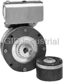
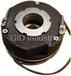
Warner Electric ERS Series Electrically Released Brakes
Part Number
ERS
Price
Request Quote
Manufacturer
WARNER ELECTRIC
Lead Time
Request Quote
Category
Motor Brakes
Datasheet

Extracted Text
Electrically Released Brakes Spring-Set Spring-Set Brakes for Static Holding and Emergency Stopping Applications ERS Typical Applications Statically engaged holding brakes are The Warner Electric ERS brake applied where the rotating shaft needs to is an ideal holding device in be held after it has stopped and is in applications where the motor a static condition. Spring-set brakes is used to stop and automatically stop and hold a load in the accurately position event of power failure or other emergency the load. stop situations. The spring clamping force provides holding torque until the brake is electromagnetically released. ERS Series Static Engaged Brakes Machine Tools ERS Brakes are used on automatic tool changers to hold the load and maintain precise positioning accuracy. ERD Typical Applications The Warner Electric line of ERD Although this brake should be engaged electrically released, dynamic, only when the shaft is at rest, it can spring-set brakes offers a high- occasionally act as a braking device on a performance, cost effective rotating shaft in an emergency situation. solution for power-off load However, it is intended to be used for holding applications. static applications. ERD Series Dual Purpose Engagement Brakes Hoist/Winch The ERD with central torque adjustment can be used to consistency stop the rated load within a fixed distance by dialing-in the proper torque level on each production hoist. The addition of a manual release allows the load to be gradually and safely lowered to the ground in the event of power failure. This brake can be engaged when the shaft is at rest or when the shaft is in motion. 86 Warner Electric 800-234-3369 Spring-Set Electrically Released Brakes Spring Set Brakes Robotics ERS Brakes can position and hold robotic equipment. Emergency braking in the event of power loss can prevent damage to equipment. Medical Equipment ERS brakes are used as parking brakes in wheelchairs and holding brakes in medical apparatus such as mammography and cat scan equipment. Automated Material Handling Systems ERS Brakes hold rollers and lift mechanisms in place, and lock drive wheels in place. Overhead Door The ERD can be used in conjunction with a photo eye. In this application, whenever the light beam is broken, voltage to the brake is removed. The brake then applies and holds the door in position. Further, the manual release feature allows the operator to open/close the door in the event of a power failure. Mobile Equipment ERS Brake, applied as a parking brake function on lift trucks, prevent rolling on slanted surfaces without the need for manual brake linkage or expensive hydraulic brakes. Warner Electric 800-234-3369 87 Electrically Released Brakes ERS Series For Static Holding and Emergency Stopping Terminals Advanced corrosion protection Provide easy electrical connections. Provided for use in the toughest industrial environments. Through holes Class H magnet wire Standard for flexible mounting. For high temperature use. Rugged spline drive Large diameter For high torque capability Through bore allows for drop- with minimal backlash. through hub attachment. No accurate axial hub positioning required. Armature Friction disc Non-asbestos friction Magnet material provides consistent torque and long life. Tapped holes Standard for flexible mounting. End plate Packaged Performance Features Principle of Operation • Designed for static holding operations Warner Electric ERS Brakes are pre- ERS Brake torque is developed when assembled and burnished at the factory. springs apply a clamping force between • Brake automatically engages when The engineering is built-in. Each unit is the brake armature and the friction disc to power is turned off checked to ensure full rated torque right the end plate. Spring clamping force • Flexible mounting out-of-the-box. Just secure the hub, bolt provides the holding torque of the brake. down the brake and wire it up. An optional • Electrically released – spring actuated To release the brake, electrical power is AC to DC control is available for use with applied to the magnet coil, generating a • Quick, quiet response for rapid all 90 volt units. Unique mounting features magnetic attractive force between the engagement make it easy to adapt the ERS Brake to armature and magnet. The magnetic force almost any application requirement. • Compact, low profile design saves space overcomes the spring action, allowing the ERS brakes are available in NEMA C-face friction disc to rotate freely. • Spline drive for high torque, minimal mounted modules. Please consult factory backlash and long life “Electrically Released” brakes are so for assistance. named because, when power is removed, • Available in five sizes. Static torque ratings from 1.5 lb.ft. to 100 lb.ft. the brake will stop and hold a load. This occurs when power is lost either • ERS-26 and ERS-42 UL approved. intentionally or unexpectedly due to a machine malfunction. When power is on, the brake electrically releases the load, allowing it to move freely. 88 Warner Electric 800-234-3369 ERS Series Electrically Released Brakes Selection Sizing Step 2 System Inertia/Emergency Stop Three factors are important for proper In an emergency stop (when power is sizing: interrupted), the ERS Brake will engage • Static holding torque requirement and bring the load to a stop. To properly ERS Selection Chart size a brake for this application, load inertia • System inertia and brake RPM must be known. This is the total inertia of 11/14/99 • Stopping time all components which are to be brought to page 137 a stop. Adding the inertia of the ERS Brake Step 1 is not necessary; it has been included in Holding Torque the selection chart. Select the size unit with torque capacity closest to, but not less than, the holding With the load inertia and brake RPM torque required. known, use the Emergency Stop Selection Chart to verify your brake selection. Simply Brake Size Holding Torque Rating lb. ft. locate the intersection of your RPM and ERS-26 1.5 inertia and make sure you are not above ERS-42 7.0 the line for the brake you selected based on Holding Torque (Step 1). If you are ERS-49 15.0 above the line, select the brake designated ERS-57 34.0 by the next higher line. ERS-68 100.0 Selection Procedure ERS Brakes are available in five models Emergency Stop Selection Chart for an optimum size to match your 100 ERS-68* application requirements. Static torque 80 ERS-49,57 capabilities range from 1.5 lb.ft. to 100 60 lb.ft. ERS-42 40 The stopping function is an important consideration when deciding which ERS-26 brake to use. Will the brake be engaged 20 and disengaged in a static condition (zero speed difference between the 10 armature disc and the friction disc)? If 8 yes, the ERS Brake is the right choice. 6 Will the brake be normally engaged and 4 disengaged in a static condition with intermittent engagements dynamically? 2 An emergency stop is a good example. ERS-68* is only rated If yes, the ERS Brake is the ideal choice. up to 2000 RPM 1 Will the brake be subject to frequent 100 200 400 600 1000 2000 3600 dynamic braking action? If yes, then a Brake Shaft Speed (RPM) Warner Electric ER, FB or ERD brake *ERS-68 is only rated up to 2000 RPM should be considered. The ERS Brake is not the best choice for use as a high cycle rate dynamic brake. Warner Electric 800-234-3369 89 2 Load Inertia (lb.ft. ) Electrically Released Brakes ERS Series Selection Step 3 Stopping Time In some applications, it is desirable to Actual stopping times depend on know how fast a brake will bring a load to application variables, which include brake rest. The time to stop a load can be temperature, electrical suppression (see determined if the system inertia and brake the brake apply time data below), holding torque are known, according to the manufacturing tolerances, friction material following equation: wear, etc. For this reason, specific stop 2 times should be evaluated under actual WR N Where: t = ERS Series Circuits application conditions. 308T t = time to stop the load in If your application has special require- 11/14/99 seconds (sec.) ments, please call us. page 138 2 WR = system inertia at the brake Step 4 location in pound-feet Select Control 2 squared (lb.ft. ) Consult the Controls Section for control product overview. The holding torque for N = speed of the brake shaft in an ERS is not adjustable. Therefore, an revolutions per minute (RPM) adjustable torque control is not required. T = rated brake holding torque in pound-feet (lb.ft.) See step 1, page 89. Brake Apply/Release Time (Typical Values) Brake Release Time Brake Apply Time (Seconds) (Seconds) Suppression Circuit A Suppression Circuit B Model 24V 90V 24V 90V 24V 90V ERS-26 0.03 0.03 0.04 0.04 0.01 0.01 ERS-42 0.05 0.06 0.10 0.10 0.01 0.02 ERS-49 0.07 0.08 0.15 0.15 0.02 0.02 ERS-57 0.11 0.11 0.15 0.15 0.02 0.02 ERS-68 0.16 0.20 0.20 0.20 0.03 0.03 Note: Release and Apply Times are armature engagement and release only. ++ 24V-1N5368 90V-1N5378 1N4004 Brake Brake 1N4004 Switch Switch Signal Signal Circuit A Circuit B 90 Warner Electric 800-234-3369 ERS Series Electrically Released Brakes Armatures/Hubs Armature Drives The rugged splined drive provides flexibility in selecting the most efficient method of coupling a load to the ERS Brake. Each ERS Screw Orientation unit size has standard splined hubs available for common shaft sizes. Recessed Hub Extended Hub Mating Splined For maximum space Mount brake first, then Member efficiency, mount hub position hub Machined spline on shaft, then mount on shaft so hub on drive brake over hub. is beyond member the brake. matches armature spline to operate brake. Drive Hub/Spline and Interface Data Mating A Key Set screw B C Set No. of Dia. Pressure Set Screw Orientation Model Bore (Not furnished) Orientation Nom. Nom. Screws Teeth Pitch Angle A .2525/ .2505 1/16 x 1/16 B ERS-26 .3150/ .3130 1/16 x 1/16 B .600 .135 6-32 14 20/40 30° .3775/ .3755 3/32 x 3/32 B .3775/ .3755 3/32 x 3/32 A .5025/ .5005 1/8 x 1/8 A ERS-42 .6275/ .6255 3/16 x 3/16 A .700 .150 8-32 19 16/32 30° A .7525/ .7505 3/16 x 3/16 B Set Screw Orientation .3775/ .3755 3/32 x 3/32 A B .5025/ .5005 1/8 x 1/8 A ERS-49 .6275/ .6255 3/16 x 3/16 A .800 .160 10-32 21 16/32 30° .7525/ .7505 3/16 x 3/16 B .8775/ .8755 3/16 x 3/16 B .5025/ .5005 1/8 x 1/8 A .6275/ .6255 3/16 x 3/16 A A ERS-57 .7525/ .7505 3/16 x 3/16 A .800 .190 1/4-20 15 10/20 30° .8755/ .8755 3/16 x 3/16 B (2) Set Screws 1.0025/1.0005 1/4 x1/4 B C 1.0025/1.0005 1/4 x 1/4 A 1.1275/1.1255 1/4 x 1/4 A B ERS-68 1.2525/1.2505 1/4 x 1/4 A .900 .190 1/4-20 22 10/20 30° 1.3775/1.3755 5/16 x 5/16 A 1.5025/1.5005 3/8 x 3/8 B Note: Involute spline data per ANSI B92. 1a-1976, Class 5. Backlash Total unit backlash includes spline and armature movement. It is typically less than one degree of rotation. Spline backlash alone is typically 15 minutes of rotation or less. Warner Electric 800-234-3369 91 Electrically Released Brakes ERS Series Mounting Mounting Orientation Mounting Requirements ERS Brakes are easily modified to 1. Mounting surface to be perpendicular to shaft with in .006" T.I.R. accommodate different mounting orientations. The brake can be mounted 2. Mounting holes to be within .015" true with either face against the mounting position to the shaft. ERS Flange Dim surface. The following mountings are possible with the standard ERS brake. 11/15/99 page 140 Through Bolt Tapped Hole Flange Provides rigid Works well where Flange mounting to support. May be through bolt brake tapped holes mounted on either mounting is im- for most versatile side of brake. practical. attachment to many different housings, motors, and frames. Optional Adapter Mounting Flange Exit for Lead Wires B A Bolt circle D matches C corresponding Drilled and brake C’sunk holes Model A Nom. B Nom. C Holes D Nom. ERS-26 4.000 .935 #4 .100 ERS-42 5.000 1.450 #6 .144 ERS-49 6.250 1.575 #8 .193 ERS-57 7.500 1.825 #10 .193 ERS-68 9.500 2.500 1/4 .224 Note: Holes for attaching flange to mounting surface to be provided by customer. 92 Warner Electric 800-234-3369 ERS Series Electrically Released Brakes Ordering Information Accessories Adapter Flanges Conduit Box Controls Model Part Number Model Part Number Model Part Number Conduit Box 5154-101-001 CBC-100-1 6003-448-101 ERS-26 686-0182 Mounts to AC to DC Control ERS-42 686-0183 ERS-49, 57 and 68 only To be used with 90V ERS brakes ERS-49 686-0184 See the Controls Section on page 141 for ERS-57 686-0185 complete information. ERS-68 686-0186 CBC-100-1 is 110 volt only Ordering Information How to Order 1. Verify that the brake is to be used in a Ordering the appropriate ERS brake for static holding/intermittent engagement your application is a simple, step-by-step application. procedure based on the intended func- tion, brake size, mounting configuration 2. Choose the correct size ERS Brake from the selection procedure on pages 89-90. and operating voltage of the unit best Select the correct brake part number for suited for your needs, including any the appropriate size and desired optional parts and accessories that you operating voltage. may require. A Warner Electric sales 3. Choose the splined hub part number for representative or distributor is always the required bore diameter and unit size. happy to provide assistance. 4. Select optional accessories, such as: adapter flange kit, AC to DC control and conduit box kit. ERS Brake Splined Hub Special Requirements ERS Brake modifications such as metric Model Voltage Part Number Model Bore Dia. Part Number bores, special voltages and low torque .250 5158-541-006 24V 5158-170-016 ERS-26 units are available. Consult factory. ERS-26 .312 5158-541-007 90V 5158-170-015 .375 5158-541-008 24V 5151-170-002 ERS-42 .375 5151-541-002 90V 5151-170-001 .500 5151-541-003 ERS-42 24V 5155-170-002 .625 5151-541-004 ERS-49 .750 5151-541-005 90V 5155-170-001 .375 5155-541-002 24V 5153-170-003 ERS-57 .500 5155-541-003 90V 5153-170-002 ERS-49 .625 5155-541-004 24V 5154-170-002 .750 5155-541-005 ERS-68 90V 5154-170-001 .875 5155-541-006 .500 5153-541-004 .625 5153-541-005 ERS-57 .750 5153-541-006 .875 5153-541-007 1.000 5153-541-008 1.000 5154-541-005 1.125 5154-541-006 ERS-68 1.250 5154-541-007 1.375 5154-541-008 1.500 5154-541-009 Warner Electric 800-234-3369 93 Electrically Released Brakes ERS Series ERS-26, ERS-42, ERS-49, ERS-57, ERS-68 K Optional* L Conduit Box J 0.875 G H 0.328 max. A CD E F 45° M Bolt Circle Internal Involute Spline P N B (4) tapped holes (4) through holes equally spaced equally spaced Q deep *Available only for the ERS-49, 57, and 68 sizes 94 Warner Electric 800-234-3369 ERS Series Electrically Released Brakes ERS-26, ERS-42, ERS-49, ERS-57, ERS-68 All dimensions are nominal, unless otherwise noted. Model A Max. B Max. C D E F G ERS-26 2.460 1.515 1.375 1.125 .860 1.250 — ERS-42 3.520 1.595 2.000 1.600 1.375 1.255 — ERS-49 4.270 1.767 2.600 1.750 1.500 1.332 3.625 ERS-57 5.020 1.937 3.240 2.100 1.750 1.503 4.000 ERS-68 6.520 2.030 4.504 2.800 2.425 1.565 4.750 Model H J K L M Dia. N Dia. P Q ERS-26 — — — — 2.125 .172/.164 4-40 .375 ERS-42 — — — — 3.125 .200/.190 6-32 .400 ERS-49 4.625 1.000 1.625 3.750 3.750 .228/.218 8-32 .400 ERS-57 5.000 1.170 1.625 3.750 4.500 .288/.278 10-24 .400 ERS-68 5.750 1.265 1.625 3.750 5.875 .413/.404 1/4-20 .500 Specifications 2 Power Current Resistance Inertia (lb.in. ) Weight (lbs.) Model Voltage DC (Watts) (Amperes) (Ohms) Static Torque (lb.ft.) Unit Hub Unit Hub 24V 17.6 0.733 32.75 ERS-26 1.5 0.03 0.004 1.20 0.06 90V 16.0 0.178 506.5 24V 23.3 0.973 24.67 ERS-42 7 0.14 0.040 2.50 0.20 90V 21.5 0.239 376.2 24V 27.3 1.136 21.12 ERS-49 15 0.45 0.060 4.30 0.25 90V 25.8 0.287 313.6 24V 36.2 1.510 15.9 ERS-57 34 0.54 0.110 6.50 0.38 90V 35.2 0.391 230.1 24V 54.9 2.286 10.5 ERS-68 100 1.44 0.550 11.30 0.75 90V 51.9 0.577 155.9 Warner Electric 800-234-3369 95 Electrically Released Brakes Spring-Set Brake Modules SSBM Series- EM/ERS Packaged Spring-Set Brake Module for Holding Applications NEMA C-face The Spring-Set Brake Module is a NEMA Compatible mounting C-face compatible unit designed to perform holding as well as occasional emergency stopping functions, making it particularly well-suited for motor brake applications. Because it is designed to be mounted on the front of a motor, it is an excellent choice for retrofitting an existing motor, or for use on custom designed machinery. Features • NEMA C-face compatible mounting • Performs holding functions with occasional e-stops • Completely assembled and Class H preburnished at the factory magnet wire • Easy to install • No adjustment required Non-Asbestos Friction Material provides • High torque, lead-free and consistent asbestos-free friction material torque and long life Principle of Operation SSBM Brake torque is developed when To release the brake, electical power is springs apply a clamping force between applied to the magnet coil, generating the brake armature and the friciton disc to a magnetic attractive force between the end plae. Spring clamping force the armature and magnet. The provides the holding torque of the brake. magnetic force overcomes the spring action, allowing the friction disc to rotate freely. Specifications Holding Unit Unit NEMA Torque Max Weight Inertia Voltage Power Current Resistance 2 Model Frame Size (ft-lbs) RPM (lbs) (lb-in ) (DC) (Watts) (Amperes) (Ohms) Part Number 24 23.3 0.973 24.67 5370-170-122 EM-50/ERS-42 56C/48Y 7.0 3600 6.4 .295 90 21.5 0.239 376.2 5370-170-123 24 27.3 1.136 21.12 5370-170-124 EM-50/ERS-49 56C/48Y 15.0 3600 8.2 .673 90 25.8 0.287 313.6 5370-170-125 182C/143TC 24 36.2 1.510 15.90 5370-170-126 EM-180/ERS-57 34.0 3600 10.4 .955 184C/145TC 90 35.2 0.391 230.1 5370-170-127 213C/182TC 24 54.9 2.286 10.50 5371-170-042 EM-210/ERS-68 100.0 2000 24.7 3.842 215C/184TC 90 51.9 0.577 155.9 5371-170-043 96 Warner Electric 800-234-3369 Spring-Set Brakes Electrically Released Brakes SSBM Series-EM/ERS 3. System Inertia/Emergency Stop Applications Sizing The Warner Electric Spring-Set Brake Four factors are important for proper In an emergency stop (when power is Module is an ideal holding device in sizing: interrupted), the SSBM will engage and applications where the motor is used to bring the load to a stop. To properly size a • Motor frame size stop and accurately position the load. The brake for this application, load inertia must SSBM brake will hold the load in that be known. This is the total inertia of all • Static holding torque requirement position until electrically realeased. The components which are to be brought to a • System inertia and brake RPM SSBM is also a cost effective emergency stop. Adding the inertia of the SSBM stopping device in the event of power Brake is not necessary as it has been • Stop time failure, machine malfunciton, or other included in the selection chart. occasional dynamic stopping. Be sure to consider each of these factors With the load inertia and brake RPM as outlined below to effectively select the Application examples include holding known, use the Emergency Stop Selection most appropriate brake for your railroad crossing arms, basketball Chart to verify your brake selection. application. backboards, robotic arms, and assemblies Simply locate the intersection of your RPM on vertical ball screws. and inertia and make sure you are not above the line for the brake you selected 1. NEMA C-face Mounting based on Holding Torque (Step 1). If you Selection are above the line, select the brake Verify the brake is to be used in a static SSBM Series Brakes are available in four designed by the next higher line. holding/intermittent engagement models with static torque capabilities application. ranging from 7.0 lb.ft. to 100 lb.ft. Based on the NEMA C-face frame size of The stopping function is an important the prime mover, select the correct brake consideration when deciding which brake module size from the Frame Size Selection to use. Will the brake be engaged and Chart. disengaged in a static condition (zero speed difference between the armature Frame Size Selection Chart disc and the friction disc)? If yes, then the NEMA Brake SSBM Brake is the right choice. Frame Size Model EM-50/ERS-42 Will the brake be normally engaged and 56C/48Y EM-50/ERS-49 disengaged in a static condition with 182C/143TC intermittent engagements dynamically? An EM-180/ERS-57 184C/145TC emergency stop is a good example. If yes, 213C/182TC EM-210/ERS-68 then the SSBM Brake is the ideal choice. 215C/184TC Will the brake be subject to frequent dynamic braking action? If yes, then a 2. Holding Torque Warner Electric EM-FBB, EUM-FBB, EM- MBFB, EUM-MBFB, EM-FBC or UM-FBC Select the size unit with the torque should be considered because these are capacity closest to, but not less than, the the best choices for use as high cycle rate holding torque required. dynamic brakes in NEMA C-face applications. Holding Torque Brake Rating (ft.lb.) Model 7.0 EM-50/ERS-42 15.0 EM-50/ERS-49 34.0 EM-180/ ERS-57 100.0 EM-210/ERS-68 Warner Electric 800-234-3369 97 Electrically Released Brakes Spring-Set Brakes Emergency Stop Selection Chart 100 Actual stopping times depend on EM-210/ERS-68 80 application variables, which include EM-50/ERS-49, EM-180/ERS-57 60 brake temperature, electrical EM-50/ERS-42 suppression (see the brake apply time 40 data below), manufacturing tolerances, friction material wear, etc. For this reason, specific stop times should be 20 evaluated under actual application conditions. 10 If your application has special 8 requirements, please call Warner Electric 6 Technical Support. 4 5. Select Control ERS Series Circuits 2 Consult the Controls Section on page EM-210/ERS-68 11/14/99 is only rated 141 for control product overview. The up to 2000 RPM 1 holding torque for a SSBM is not page 138 100 200 400 600 1000 2000 3600 adjustable: therefore, an adjustable Brake Shaft Speed (RPM) torque control is not required. 4. Stopping Time In some applications, it is desirable to t = time to stop the load in seconds Special Requirements know how fast a brake will bring a load (sec.) SSBM brake modifications, such as to rest. 2 special voltages, rear motor mounting, WR = system inertia at the brake 2 and low torque units are available. The time to stop a load can be location in pound-feet squared (ft.lb ) determined if the system inertia and Contact Warner Electric Technical N = speed of the brake shaft in brake holding torque are known, Support at 800-825-9050. revolutions per minute (RPM) according to the following equation: 2 T = rated brake holding torque in foot- Where: t = (WR N) /(308T) pounds (ft.lb.) Brake Apply/Release Time (Typical Values) Brake Release Time Brake Apply Time (Seconds) (Seconds) Suppression Circuit A Suppression Circuit B Model 24V 90V 24V 90V 24V 90V EM-50/ERS-42 0.05 0.06 0.10 0.10 0.01 0.02 EM-50/ERS-49 0.07 0.08 0.15 0.15 0.02 0.02 EM-180/ERS-57 0.11 0.11 0.15 0.15 0.02 0.02 EM-210/ERS-68 0.16 0.20 0.20 0.20 0.03 0.03 Note: Release and Apply Times are armature engagement and realease only. ++ 24V-1N5368 90V-1N5378 1N4004 Brake Brake 1N4004 Switch Switch Signal Signal Circuit A Circuit B 98 Warner Electric 800-234-3369 2 Load Inertia (lb.ft. ) Spring-Set Brakes Electrically Released Brakes SSBM Series-EM/ERS All dimensions are nominal, unless otherwise noted. H A C E Model Max B Max D Max F G Dia Key (4) 3/8-16 EM-50 5.232 3.125 .475 .937 .156 UNC 6.688 .625 3/16x3/16 on 5.875 Dia (4) 3/8-16 EM-180 5.292 3.125 .475 .937 .156 UNC 6.688 .875 3/16x3/16 on 5.875 Dia (4) 1/2-13 EM-210 7.579 4.609 .562 1.500 .315 UNC 9.344 1.125 1/4x1/4 on 7.250 Dia Model J K L M N P R S T U 4.500 .625 EM-50 2.212 3/16x3/16 1.437 30° 36 45° 3.25 2.188 Pilot Dia Dia 4.500 .875 EM-180 2.216 3/16x3/16 1.437 30° 36 45° 3.25 2.188 Pilot Dia Dia 8.500 1.125 EM-210 3.002 1/4x1/4 2.125 25° 36 45° 3.25 2.188 Pilot Dia Diza Warner Electric 800-234-3369 99 Electrically Released Brakes ERD Series Dynamic Braking With Reliable, Fast Response Continuous Duty Coil Epoxy-sealed; windings have Class The Warner Electric line of electrically F insulation. Lead wires have stan- released, dynamic, spring-set brakes dard Class B insulation rating. (ERD) offers a high-performance, cost effective solution for power-off load Friction Carrier holding applications. Double friction surfaces for increased torque in small package size. These brakes are designed to safely keep the load in position in the event of a power or motor failure, whether Central Torque Adjustment intentional or accidental. An (optional) Allows braking torque adjustment down to 50% of optional manual release allows nominal rating; ideal for the operator to safely move the controlling stopping distances. load even when no power is available. Splined Center Hub By applying voltage to the ERD, Steel for wear resistance and an electromagnetic field is available in a variety of bore sizes and keyways. created which causes the armature plate to pull-in against helical compression springs, Compression Springs thus releasing the brake. Used to provide balanced armature plate loading. When power is removed, the springs force the armature to compress the Mounting Flange friction carrier against the Easily modified to suit unique bolt patterns. In special cases, brakes may mounting flange, thus stopping be mounted directly to the motor and holding the load. Fully without the need for the flange. dynamic friction material on the carrier allows for repeated braking cycles from full motor speed with no Air Gap Factory pre-set and easy to adjust torque fade. during field maintenance. Features • Spring-set design holds the load in • Low power requirements for energy place when voltage is removed from the savings. brake. Dynamic friction material can stop • Eight different sizes ranging from loads from motor speeds 3.3 inches to 9.9 inches in diameter. up to 3600 RPM. • Torque capacities from 4 to 220 lb.ft. • Few moving parts mean quiet operation • Bi-directional stopping capability. • Lead and asbestos free, dynamic friction material is suited for high Options cycle rates. Manual Release Allows the brake to be released by hand; • Adjustable air gap for ease of service and long life in the field. ideal for lowering suspended loads. • Variety of voltages available. Dust Cover Shields the brake actuation system from • Simple DC control (or AC with available rectifiers). external dust and debris. 100 Warner Electric 800-234-3369 ERD Design Variations ERD Design Variations 11/15/99 11/15/99 page 145 page 145 ERD Series Electrically Released Brakes Selection ERD Design Variations ERD Design Variations Design Variations Torque Adjustment 11/15/99 11/15/99 Brakes are factory set at the minimum page 145 page 145 torque rating shown in the VAR 0 VAR 2 Specifications chart. Torque preset and Central ring nut constant adjusts torque Friction Disc Carriers • No torque • Up to 50% Replaceable Friction carriers are adjustments torque reduction available possible possible in two types: • Available in all • Available in all sizes • Metallic Standard on all brakes sizes • Thermoplastic can be used as an option on sizes 5 and 10 brakes only VAR 1 VAR 3 Four screw torque Four screw torque adjustment adjustment with provision for • Up to 50% torque reduction tachometer possible • Up to 50% • Available in sizes torque reduction 5, 10, 20 and 35 possible only • Mounting holes for tachometer • Available in sizes 5, 10, 20 and 35 only Note: VAR 2 and VAR 0 are most common. Specifications 2 Holding Torque Max. Speed Rotating Inertia (lb. in. ) Current Draw (Amps) Resistance (Ohms) Weight Size lb. in. lb. ft. RPM Thermoplastic Metallic Disc 24 96 190 215 24 96 190 215 (lbs.) ERD-5 45 3.75 3600 0.041 0.103 0.83 0.21 0.11 0.09 28.9 454 1775 2380 2 ERD-10 85 7.08 3600 0.137 0.321 1.03 0.26 0.13 0.12 23.4 372 1450 1813 4 ERD-20 175 14.58 3600 0.957 1.22 0.31 0.16 0.14 19.6 310 1209 1545 7 ERD-35 310 25.83 3600 2.529 1.61 0.41 0.21 0.18 14.9 233 912 1175 10 ERD-60 530 44.17 3000 7.415 1.94 0.577 0.293 12.4 166.2 648.1 14 ERD-100 890 74.17 3000 12.472 2.35 0.569 0.302 10.22 168.6 628.5 22 ERD-170 1500 125.00 3000 14.010 2.73 0.69 0.375 8.78 139.2 507.2 34 ERD-300 2650 220.83 3000 29.386 4.11 1.122 0.602 5.83 85.63 315.6 57 Warner Electric 800-234-3369 101 Electrically Released Brakes ERD Series Selection Dynamic Torque 220 ERD-300 185 150 ERD-170 110 75 ERD-100 ERD-60 37 0 100 500 1000 1500 2000 2500 3000 Proper ERD brake selection involves RPM determining,in order: 30 1. Static Holding Torque The ERD brake nominal holding ERD-35 torque should exceed the torque from 22.5 the load by a minimum safety factor of 2.0 ERD-20 2. Dynamic Torque 15 This is determined from the equation: ERD-10 5250 P T = 7.5 N ERD-5 where: T = Dynamic Torque in lb.ft. 0 N = Motor Speed in RPM 0 100 500 1000 1500 2000 2500 3000 3500 P = Motor Horsepower RPM Once the dynamic torque has been Energy Capacity calculated, check the dynamic torque curves (adjacent) at the required 1,000,000 operating speed to determine the ERD-300 ERD-170 ERD-100 suitable brake. ERD-60 3. Energy Capacity 100,000 ERD sizing by energy capacity is a function of the cycling frequency (cycles per hour) and the single cycle ERD-35 energy put into the brake as 10,000 ERD-20 determined from the equation: ERD-10 2 2 N ERD-5 E = 1.7 x WR ( ) 100 1,000 where: E = Single Cycle Energy in lb.ft. 2 2 WR = Load Inertia in lb.ft 100 N = Speed in RPM 1 10 100 1,000 Cycles per Hour Applying the energy per cycle with the cycle rate to the energy curve, the Note: To convert Joules/min. to ft.lbs./min, multiply times .7376 brake selection is verified. 102 Warner Electric 800-234-3369 Friction Work in Joules Torque in lb.ft. Torque in lb.ft. ERD Series Electrically Released Brakes Ordering Information How to Order Fully Assembled Unit Specify ERD Connections Dust 1. ERD Series Cover Manual Release page 147 2. Size: 5, 10, 20, 35, 60, 100, 170, or 300 3. Variation 0 – No torque adjustment 1 – With torque adjusting screws 2 – With central torque adjusting ring 3 – With mounting holes for tachometer 4. Voltage 24 DC is standard 12, 96, 190, and 215 DC Thick are modifications Friction Plate 5. Friction Carrier Electrical Connection Metallic carrier is standard Thermoplastic carrier is available on Typical brake unit (VAR 2) with options installed sizes 5 and 10 6. Bore Size Connections ERD-5: 1/2" max ERD-10: 5/8" max 1.82 0.72 ERD-20: 1" max 1.58 ERD-35: 1-1/8" max ERD-60: 1-1/4" max 1.07 ERD-100: 1-3/8" max 0.95 ERD-170: 1-3/4" max ERD-300: 1-3/4" max 7. Mounting Flange Thick Flange is standard Rectifiers Thin Flange available up to size 35 AC Input DC Output Rectifier Part No. 8. Mounting Screws 240/220 V 96 V Half Wave ACG830A1P1 Short Kit is standard 415/380 V 190 V Half Wave ACG830A1P1 Long Kit is available 240/220 V 190 V Full Wave ACG830A1P2 110 V 96 V Full Wave ACG830A1P2 9. Options Max. current = 1 AMP CG830 A1P1 Dust Cover = 2 AMP CG830 A1P2 Manual Release Mounting Options Flange Type Screw Kit Mounting Style Thick Short Standard – Customer Mounting via Hole Pattern H Thin Long Customer Mounting via Hole Pattern E None Long Customer Mounting via Hole Pattern E Warner Electric 800-234-3369 103 Electrically Released Brakes ERD Series Dimensions–Brake Units VAR 2 VAR 0 VAR 1 VAR 3 L E A W D N M Y S Z U K ERD Size A D Max. E K L Max. M +0.000/-0.008 N 5 3.307 0.5 2.835 1.378 1.575 0.709 0.071 10 4.016 0.625 3.543 1.614 1.831 0.787 0.098 20 5.000 1 4.409 1.870 2.165 0.787 0.138 35 5.787 1.125 5.197 2.146 2.559 0.984 0.118 60 6.378 1.25 5.709 2.520 2.933 1.181 0.118 100 7.402 1.375 6.693 2.795 3.209 1.181 0.118 170 8.465 1.75 7.717 3.268 3.780 1.378 0.177 300 9.921 1.75 9.055 3.819 4.528 1.575 0.197 ERD Size S U +/-0.002 W Y Z Bolt Pattern Variations Available 5 0.748 0.006 0.925 1.299 4xM4 0, 1, 2, 3 10 0.945 0.006 1.122 1.594 4xM5 0, 1, 2, 3 20 1.378 0.008 1.594 2.224 4xM5 0, 1, 2, 3 35 1.575 0.008 1.909 2.244 4xM5 0, 1, 2, 3 60 1.890 0.012 2.303 0, 2 100 2.047 0.012 2.500 0, 2 170 2.362 0.012 2.894 0, 2 300 2.874 0.012 3.484 0, 2 For service information, request manual P-229. 104 Warner Electric 800-234-3369 ERD Series Electrically Released Brakes Dimensions–Accessories Friction Plates P f e h B E E J C G H F f 0.06 Thick Friction Plate (Standard – all sizes) Thin Friction Plate (Sizes 5 thru 35 only) ERD Friction Options fh eBolt Bolt Bolt Clearance Clearance ERD Size B C E Pattern Holes F G H Holes J P 5 3.268 0.787 2.835 3xM4 3x0.177 1.654 3.425 1.181 3x0.177 0.079 0.236 10 3.937 1.181 3.543 3xM5 3x0.217 2.126 4.213 1.772 3x0.217 0.079 0.276 20 4.921 1.575 4.409 3xM6 3x0.256 2.362 5.217 2.205 3x0.256 0.118 0.354 35 5.709 1.772 5.197 3xM6 3x0.256 2.953 6.004 2.441 3x0.256 0.118 0.354 60 6.299 2.165 5.709 3xM8 3x0.335 3.346 6.732 2.913 3x0.335 0.118 0.433 100 7.283 2.559 6.693 3xM8 3x0.335 3.858 7.717 3.307 3x0.335 0.118 0.433 170 8.346 2.953 7.717 6xM8 6x0.335 3.937 6x0.335 0.118 0.433 300 9.843 3.543 9.055 6xM10 6x0.413 4.724 6x0.413 0.118 0.433 The thick mounting flange provides the proper material and mounting tolerances for the brake. The thin mounting flange provides the proper material in applications where flatness, squareness and concentricity requirements are met on the machine already. Manual Release Release Angle CC ERD Size AA BB CC DD EE Release Angle AA 5 3.86 2.09 0.67 3.46 3.46 10 Dust Cover 10 4.21 2.44 0.71 4.17 4.17 8 BB 20 5.08 2.99 0.98 5.20 5.20 7 35 5.47 3.39 0.87 5.98 5.98 7 DD 60 6.75 4.09 1.61 6.06 6.54 7 100 7.74 4.72 1.73 7.01 7.36 7 170 9.57 5.51 2.09 7.99 8.78 10 300 12.44 6.38 2.36 9.33 10.33 10 EE Warner Electric 800-234-3369 105
Frequently asked questions
How does Industrial Trading differ from its competitors?

Is there a warranty for the ERS?
Which carrier will Industrial Trading use to ship my parts?
Can I buy parts from Industrial Trading if I am outside the USA?
Which payment methods does Industrial Trading accept?


What they say about us
FANTASTIC RESOURCE
One of our top priorities is maintaining our business with precision, and we are constantly looking for affiliates that can help us achieve our goal. With the aid of GID Industrial, our obsolete product management has never been more efficient. They have been a great resource to our company, and have quickly become a go-to supplier on our list!
Bucher Emhart Glass
EXCELLENT SERVICE
With our strict fundamentals and high expectations, we were surprised when we came across GID Industrial and their competitive pricing. When we approached them with our issue, they were incredibly confident in being able to provide us with a seamless solution at the best price for us. GID Industrial quickly understood our needs and provided us with excellent service, as well as fully tested product to ensure what we received would be the right fit for our company.
Fuji
HARD TO FIND A BETTER PROVIDER
Our company provides services to aid in the manufacture of technological products, such as semiconductors and flat panel displays, and often searching for distributors of obsolete product we require can waste time and money. Finding GID Industrial proved to be a great asset to our company, with cost effective solutions and superior knowledge on all of their materials, it’d be hard to find a better provider of obsolete or hard to find products.
Applied Materials
CONSISTENTLY DELIVERS QUALITY SOLUTIONS
Over the years, the equipment used in our company becomes discontinued, but they’re still of great use to us and our customers. Once these products are no longer available through the manufacturer, finding a reliable, quick supplier is a necessity, and luckily for us, GID Industrial has provided the most trustworthy, quality solutions to our obsolete component needs.
Nidec Vamco
TERRIFIC RESOURCE
This company has been a terrific help to us (I work for Trican Well Service) in sourcing the Micron Ram Memory we needed for our Siemens computers. Great service! And great pricing! I know when the product is shipping and when it will arrive, all the way through the ordering process.
Trican Well Service
GO TO SOURCE
When I can't find an obsolete part, I first call GID and they'll come up with my parts every time. Great customer service and follow up as well. Scott emails me from time to time to touch base and see if we're having trouble finding something.....which is often with our 25 yr old equipment.
ConAgra Foods