

 Manufacturers
VMIC VMIVME-3128
Description
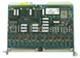
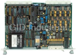
VMIC VMIVME-3128 Scanning 14-bit Analog-to-Digital Converter Board with Programmable Gain Memory
Part Number
VMIVME-3128
Price
Request Quote
Manufacturer
VMIC
Lead Time
Request Quote
Category
Analog-to-Digital Converters
Specifications
Altitude
Operation to 10,000 ft (3,048 m)
Cooling
Forced air convection (standard VMEbus slot)
Dimensions
Double height Eurocard (6U) board, 160 x 233.35 mm
Humidity
10 to 80 percent relative, noncondensing
Input Connectors (P3, P4)
96-pin DIN connector, center row grounded (accepts 64- and 96-pin mating connectors).
MTBF
131,900 hours (217F)
Power Requirements
4.0 A (maximum) at +5 VDC
Temperature
0 to +55 °C, operating (standard VME slot) -40 to +85 °C, storage
Features
- 1,024-word data buffer (16-word deep buffer x 64 channels)
- 14-bit A/D conversion
- 58 kHz conversion rate
- 64 differential or single-ended inputs
- Autoscanning mode
- Continually digitizes all input channels and stores the results
- External trigger to synchronize multiple boards simultaneously
- Gain loading mode
- Jumper-selectable A/D ranges of 0 to +5, 0 to +10, ± 2.5, ±5, and ±10 V
- Locally triggered burst mode
- Optional low pass ?lter
- Overvoltage protected inputs
- Powers up in autoscanning mode with gain of 1
- Program-selectable scanning of 16, 32, 48, or 64 channels
- Programmed VMEbus interrupts
- Remotely triggered burst mode
- Selectable output coding
- Single channel random polling mode
- Six operating modes
- Software-programmable gain 1, 10, 100
- Timed burst mode
- User-programmable interval timer
Datasheet

Extracted Text
VMIVME-3128 Scanning 14-bit Analog-to-Digital Converter Board with Programmable Gain Memory • 64 differential or single-ended inputs • 14-bit A/D conversion • 58 kHz conversion rate • Program-selectable scanning of 16, 32, 48, or 64 channels • Continually digitizes all input channels and stores the results • Six operating modes — Autoscanning mode — Single channel random polling mode — Timed burst mode — Locally triggered burst mode — Remotely triggered burst mode — Gain loading mode • Programmed VMEbus interrupts • User-programmable interval timer • Software-programmable gain 1, 10, 100 • External trigger to synchronize multiple boards simultaneously • Jumper-selectable A/D ranges of 0 to +5, 0 to +10, ± 2.5, ±5, and ±10 V • Optional low pass filter • Overvoltage protected inputs • 1,024-word data buffer (16-word deep buffer x 64 channels) • Selectable output coding • Powers up in autoscanning mode with gain of 1 APPLICATIONS • Factory automation and instrumentation Ordering Options • Process control and monitoring April 14, 1998 800-003128-000 E ABC – D E F • Laboratory instrumentation • Machine monitoring VMIVME-3128* –0 – • Data acquisition and control A = Input Filter Options 0 = No Filter 1 = 10 Hz ±24% (-3 dB) INTRODUCTION — This product is designed to 2 = 50 Hz ±24% (-3 dB) support 64 channels of differential or single-ended wide 3 = 100 Hz ±24% (-3 dB) 4 = 500 Hz ±24% (-3 dB) range (±25 mV to ±10 V) analog inputs. 9 = 1.6 kHz ±24% (-3 dB) B = 0 (Option reserved for future use) The board supports the following operating modes which C = Input Option 0 = 64 Diff/SE Analog Input Channels are described below: 1 = 64 SE Analog Inputs with Improved High Frequency Rejection Autoscanning Connector Data Single Channel Random Polling Style Recommended Connecting Component P3 and P4 I/O Connectors Timed Burst 64-pin IDC Mating Connector (64-pin) Panduit 120-964-435E Locally Triggered Burst Strain Relief (for 64-pin Connectors) Panduit 100-000-032 Remotely Triggered Burst 96-pin Mating Connector (96-pin Discrete) AMP 925486-1 Discrete Female Crimp Contacts (96-pin Discrete) AMP 530151-6 ** Gain Loading Wire Connector Housing Harting 09 03 096 0501 (for 96-pin Connectors) One thousand and twenty-four dual-port Data Registers 96-pin IDC Mating Connector (96-pin Mass Terminated) ERNI 913.031 provide storage for continuous scanning of all channels. The 0.033-inch Ribbon Cable ERNI 913.049 scanning modes are executed automatically at powerup, (96-pin Mass Terminated) system reset, or are entered under program control. The Strain Relief Insert Harting 09 02 000 9912 dual-port registers allow VMEbus access at any time to read (0.033-inch Ribbon Cable) Connector Housing Harting 09 03 096 0501 the latest stored data. (for 96-pin Connectors) Channel gain can be jumper selected as x1, x10, or x100, PC Board I/O Connector Part Number Panduit 101-096-033A or can be software programmed individually for each Notes channel. Scan rate is programmable up to 58 kCPS (thousand * -9BC must be ordered when VMIC signal conditioning products are coupled with the VMIVME-3128. channels/s. Low pass input filters are available. ** AMP crimp tool part number 90301-2. For Ordering Information, Call: A functional block diagram is provided in Figure 1, and 1-800-322-3616 or 1-256-880-0444 • FAX (256) 882-0859 the Ordering Options are provided on the first page of this E-mail: info@vmic.com Web Address: www.vmic.com Copyright© March 1995 by VMIC specification. Specifications subject to change without notice. VMIC • 12090 South Memorial Parkway • Huntsville, Alabama 35803-3308 1 VMIVME-3128 Board Address: Jumper located on word boundary The VMIVME-3128 employs an unbuffered 64-channel anywhere in the short I/O A16 space, or the standard A24 input multiplexer. Systems Integrators must consider source space. Required word boundary is 1000h in either space. impedances and cable length when using this board unless the VMIVME-3413, VMIVME-3417A, VMIVME-3418, or other VMEbus Access: Response to address modifiers is signal conditioning is used. If these signal conditioning jumper-selectable as: products are used with the VMIVME-3128, then the Short I/O A16 or standard A24 address space VMIVME-3128-9BC must be ordered. In those applications Supervisory or user privilege, or both where no signal conditioning board is used or where extremely Data or program access low noise is required, VMIC recommends the VMIVME-3122. VMEbus Compliance: This product complies with VMEbus Specification ANSI/IEEE STD 1014-1987 IEC FUNCTIONAL CHARACTERISTICS 821 and 297 with the following mnemonics: (Typical at +25 °C and rated power supplies, unless A24/A16:D16/D8 (EO) DTB Slave otherwise stated.) Interrupter I(1 to 7) ROAK (DYN) Operating Modes: Interrupter Vector: D08 (O) (DYN) 6U form factor Autoscanning Mode: This default operating mode is selected by a reset operation, or by clearing both CSR VMEbus Interrupt: An interrupt request can be Mode control bits. All active channels are scanned generated at the end of a buffer scan in all modes except continuously in this mode, and any channel value can be autoscanning mode. Response vectors are controlled read at any time. through Interrupt Vector Registers. Single Channel Random Polling Mode: Each input Data Ready Flag: A data ready flag in the CSR is set channel is accessed individually, and the digitized when the data buffer is filled (endscan) or half-filled channel value is read from the Converter Data Register (midscan). (CDR). Interval Timer: Bursts intervals of up to 536 s are Timed Burst Mode: A single data burst (scan of all buffer provided by a programmable interval timer. locations) is acquired at the end of a programmed interval, Reset Operations: Board reset occurs in response to a or the process can be repetitive. system reset or by setting a reset bit in the CSR. For Locally Triggered Burst: A single burst is initiated programming-free initial operation, a reset operation through the Control and Status Register (CSR). automatically establishes the following default conditions: Remotely Triggered Burst: A single data burst (scan of all enabled channels) is initiated through the P2 connector by Autoscanning mode an external TTL trigger source. 64-channel block size 64-channel data buffer Gain Loading Mode: If the board is jumper configured for Channel Gain = x1 automatic gain control, gain loading is performed by first selecting the gain loading mode, and by then loading the PGA: Channel gains of x1, x10, and x100 are selected gain code for each channel into a 64-location gain buffer. through a Programmable Gain Amplifier (PGA). PGA The gain codes (0 for x1, 1 for x10, 2 for x100) for all gain can be jumper configured with a single gain for all channels are initialized to zero (gain = x1) automatically channels, or it can be controlled in real-time with unique after a reset operation. gains assigned for each channel. See Channel Autogain. Channel Autogain: The unique gain code for each channel Panel Indicator: Program-controlled front panel LED is loaded from the VMEbus into a gain buffer (see Gain is energized during reset, and is extinguished through the Loading Mode). The assigned code is retrieved from the CSR. buffer in real-time for each channel acquisition. Board Identification: A Board Identification Register Synchronization: A single scan or burst, can be initiated by (BIR) contains the VMIVME-3128 identification code. an external TTL trigger through the P2 connector (Remotely INPUT CHARACTERISTICS Triggered Burst), or locally through the CSR (Locally Triggered Burst). Either event generates a P2 trigger output, Number of Input Channels: 64 differential or which can be used to synchronize up to 15 boards. single-ended channels 2 For Ordering Information, Call: 1-800-322-3616 or 1-256-880-0444 • FAX (256) 882-0859 VMIVME-3128 Full-Scale Input Ranges: ±2.5, ±5, ±10, 0 to +5, 0 to TRANSFER CHARACTERISTICS +10 V; jumper-selectable Resolution: 14 bit Channel Gain: Program selected or jumper selected as Input Sampling: Sequential, starting at channel 00 x1, x10, or x100. See Channel Autogain. Integral Nonlinearity: ±0.005 percent maximum; from Full-Scale Input Range: ±25 mV to ±10 V best straight line Input Offset Voltage: Differential Nonlinearity: ±0.0015 percent; typical at (0.3 + 6/G + 0.6 k) mV; MSB transition where: G = PGA gain K = Sample rate per channel, KSPS Quantization Error: ±1/2 LSB e.g.: The maximum input offset voltage with Missing Codes: None a PGA gain of x10 and a sample rate * of 0.5 KSPS per channel would be Conversion Cycle Time : 17 µs, total time for 1.2 mV (0.3 + 0.6 + 0.3) acquisition, A/D conversion, and storage Input Bias Current: 50 nA maximum at zero input A/D Conversion Rate: 58 KSPS (thousand samples per second) Input Impedance: 5 MΩ in parallel with 50 pF Channel Sample Rate (Maximum): 3.625 KSPS Input Noise: 0.3 mV RMS, DC to 100 Hz (58 KSPS ÷ number of channels in scanning block, 16 Input Filters: Optional low pass single-pole filters: channels minimum) -3 dB at 10 Hz ±24% Timed Burst Interval: 305 µs to 536 s -3 dB at 50 Hz ±24% Interchannel Crosstalk: -3 dB at 100 Hz ±24% -3 dB at 500 Hz ±24% Filter Option Cross Talk Cross Talk -3 dB at 1.6 kHz ±24% (Maximum) (Maximum) (Adjacent (Alt. Overvoltage Protection: Channels) Channels) None -80 dB -110 dB Sustained Overvoltage 10 Hz -70 dB -110 dB Maximum 50 Hz -70 dB -110 dB Option Power On Power Off 100 Hz -70 dB -110 dB -000 ±16 V ±4 V 500 Hz -70 dB -110 dB -100 ±31 V ±23 V 1.6 kHz -77 dB -110 dB -200 ±21 V ±10 V Common-Mode Voltage: CMV = ±9 V; maximum -300 ±21 V ±10 V input voltage = ±11 V on either input line for linear operation. -400 ±21 V ±10 V -900 ±16 V ±4 V Common-Mode Rejection: CMRR = 82 dB, DC to 100 Hz, 64-channel block size. -001 ±24 V ±16 V Data Coding: Program selectable as two’s complement, or straight/offset binary. 14-bit data is -101 ±40 V ±33 V left-justified in a 16-bit data word. -201 ±24 V ±16 V ACCURACY -301 ±24 V ±16 V -401 ±24 V ±16 V PGA Nonlinearity, DC: G=1: ±0.005 percent FSR (Full-Scale Range) -901 ±17 V ±5 V G=10: ±0.005 percent FSR G=100: ±0.01 percent FSR * Each channel is sampled during the A/D conversion of the preceding channel. VMIC • 12090 South Memorial Parkway • Huntsville, Alabama 35803-3308 3 VMIVME-3128 Gain Accuracy (Including Nonlinearity): PHYSICAL/ENVIRONMENTAL G=1: ±0.008 percent FSR Temperature: G=10: ±0.06 percent FSR 0 to +55 °C, operating (standard VME slot) G=100: ±0.06 percent FSR -40 to +85 °C, storage STABILITY (Over Temperature Range) Humidity: 10 to 80 percent relative, noncondensing PGA Offset Voltage Drift: ±(3 + 15/G) µV/°C Altitude: Operation to 10,000 ft (3,048 m) System Accuracy Drift: Cooling: Forced air convection (standard VMEbus G=1: ±20 PPM/°C slot) G=10: ±50 PPM/°C G=100: ±90 PPM/°C Dimensions: Double height Eurocard (6U) board, 160 x 233.35 mm Total Noise: 4,500 µV maximum at GAIN = 1 and FS = ±10 V Input Connectors (P3, P4): 96-pin DIN connector, center row grounded (accepts 64- and 96-pin mating DATA BUFFER MEMORY connectors). Buffer Size: 16 to 1,024 contiguous 16-bit data words, in Power Requirements: 4.0 A (maximum) at +5 VDC six equal ratios of 2:1; program controlled. MTBF: 131,900 hours (217F) Block Size: 16, 32, 48, or 64 channels; program controlled. TRADEMARKS VMEbus Access: D8 or D16 The VMIC logo is a registered trademark of VMIC. Other registered trademarks are the property of their Availability: Accessible at any time from the VMEbus. respective owners. Buffer and block sizes are controlled through a Buffer Control Register (BCR). APPLICATION AND CONFIGURATION GUIDES — The following Application and Configuration Guides are available from VMIC to assist the user in the selection, specification, and implementation of systems based on VMIC’s products. Title Document No. Digital Input Board Application Guide 825-000000-000 Change-of-State Board Application Guide 825-000000-002 Digital I/O (with Built-in-Test) Product Line Description 825-000000-003 Synchro/Resolver (Built-in-Test) Subsystem Configuration Guide 825-000000-004 Analog I/O Products (with Built-in-Test) Configuration Guide 825-000000-005 Connector and I/O Cable Application Guide 825-000000-006 Integration of the VMIVME-5588 with GE Fanuc PLC 825-000000-025 Data Acquisition Noise Reduction Application Guide 825-000000-026 IOWorks Base Package Application Guide 825-000000-027 IOWorks Systems Application Guide 825-000000-028 4 For Ordering Information, Call: 1-800-322-3616 or 1-256-880-0444 • FAX (256) 882-0859 VMIVME-3128 P3 ANALOG 32 DIFF. PAIRS LOW PASS PROGRAMMABLE MUX 8 DIFF. FILTERS GAIN AMPLIFIER PAIRS (OPTIONAL) (PGA) (8) ANALOG 2 TRACK-AND- MUX 14-bit 8 DIFF. HOLD P4 PAIRS (SE) ADC DIFF. ANALOG AMPLIFIER 32 DIFF. (1) PAIRS LOW PASS MUX FILTERS HOLD CONV BOARD (OPTIONAL) (8) 4 CONV COMPL 14 MUX 2 SELECT DUAL-PORT DUAL-PORT REGISTERS P1 GAIN AND REGISTERS CONTROL 14 ADC DATA P2 4 VMEbus ADC ADC FOUNDATION TIMING CONTROL EXT CNVT TRIGGER LOGIC EOC COUNT INT COMPL BUS INTERRUPTER PROGRAMMABLE TIMER MODULE (BIM) Figure 1. VMIVME-3128 Functional Block Diagram 90 80 70 60 CMRR dB 50 40 30 20 0 0.5 1 1.5 2 2.5 3 3.5 4 4.5 5 Log (f) Figure 2. VMIVME-3128 Common-Mode Rejection Ratio Versus Frequency VMIC • 12090 South Memorial Parkway • Huntsville, Alabama 35803-3308 5
Frequently asked questions
How does Industrial Trading differ from its competitors?

Is there a warranty for the VMIVME-3128?
Which carrier will Industrial Trading use to ship my parts?
Can I buy parts from Industrial Trading if I am outside the USA?
Which payment methods does Industrial Trading accept?
Why buy from GID?

Quality
We are industry veterans who take pride in our work

Protection
Avoid the dangers of risky trading in the gray market

Access
Our network of suppliers is ready and at your disposal

Savings
Maintain legacy systems to prevent costly downtime

Speed
Time is of the essence, and we are respectful of yours
Related Products
32-Channel Scanning 12-bit Analog-to-Digital Converter Board for PC/AT
32-Channel Optically-Isolated 12-bit Analog-to-Digital Converter Board for PC/AT
VMIC VMIVME-3100 CPU Board - 16-Channel 12-Bit Analog-To-Digital Converter Board
VMIC VMIVME-3111 48 Analog-to-Digital Inputs 2-Channel Digital-to-Analog Output Boards

VMIVME-3118 32-Channel 16-Bit A/D Converter Module
VMIC VMIVME-3120 Analog to Digital Converter Board
Request a Quote

The quote request has been received
Close

Facing challenges or have inquiries? Feel free to contact us!
Call Us +1-469-283-2440
What they say about us
FANTASTIC RESOURCE
One of our top priorities is maintaining our business with precision, and we are constantly looking for affiliates that can help us achieve our goal. With the aid of GID Industrial, our obsolete product management has never been more efficient. They have been a great resource to our company, and have quickly become a go-to supplier on our list!
Bucher Emhart Glass
EXCELLENT SERVICE
With our strict fundamentals and high expectations, we were surprised when we came across GID Industrial and their competitive pricing. When we approached them with our issue, they were incredibly confident in being able to provide us with a seamless solution at the best price for us. GID Industrial quickly understood our needs and provided us with excellent service, as well as fully tested product to ensure what we received would be the right fit for our company.
Fuji
HARD TO FIND A BETTER PROVIDER
Our company provides services to aid in the manufacture of technological products, such as semiconductors and flat panel displays, and often searching for distributors of obsolete product we require can waste time and money. Finding GID Industrial proved to be a great asset to our company, with cost effective solutions and superior knowledge on all of their materials, it’d be hard to find a better provider of obsolete or hard to find products.
Applied Materials
CONSISTENTLY DELIVERS QUALITY SOLUTIONS
Over the years, the equipment used in our company becomes discontinued, but they’re still of great use to us and our customers. Once these products are no longer available through the manufacturer, finding a reliable, quick supplier is a necessity, and luckily for us, GID Industrial has provided the most trustworthy, quality solutions to our obsolete component needs.
Nidec Vamco
TERRIFIC RESOURCE
This company has been a terrific help to us (I work for Trican Well Service) in sourcing the Micron Ram Memory we needed for our Siemens computers. Great service! And great pricing! I know when the product is shipping and when it will arrive, all the way through the ordering process.
Trican Well Service
GO TO SOURCE
When I can't find an obsolete part, I first call GID and they'll come up with my parts every time. Great customer service and follow up as well. Scott emails me from time to time to touch base and see if we're having trouble finding something.....which is often with our 25 yr old equipment.
ConAgra Foods