

 Manufacturers
VMIC VMIVME-2532A

Description
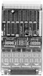
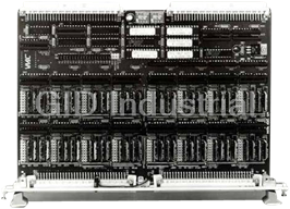
VMIC VMIVME-2532A Digital I/O - 32-Bit Digital I/O Module
Part Number
VMIVME-2532A
Price
Request Quote
Manufacturer
VMIC
Lead Time
Request Quote
Category
Digital I/O
Features
- 32 bits of high-voltage inputs
- 32 bits of high-voltage outputs
- 5 to 48 V input voltage range
- 8- or 16-bit data transfers
- Automatic surge current shutdown protection option
- Built-in-Test (off-line and real-time support)
- Compatible with VMIC’s family of intelligent I/O controllers
- Front panel with fail LED
- High breakdown voltage (70 V)
- High current sink (600 mA)
- Optional output test jumpers for 100 percent testing of output drivers
- Output clamp diodes
- Power up replacement
- Thermal shutdown protection for driving incandescent or inductive loads
- Voltage sourcing or current sinking input
Datasheet

Extracted Text
VMIVME-2532A 32-bit High-Voltage Digital Input/Output Board • 32 bits of high-voltage outputs — High current sink (600 mA) — High breakdown voltage (70 V) — Output clamp diodes — Automatic surge current shutdown protection option — Thermal shutdown protection for driving incandescent or inductive loads • 8- or 16-bit data transfers • 32 bits of high-voltage inputs — 5 to 48 V input voltage range — Voltage sourcing or current sinking input • Built-in-Test (off-line and real-time support) • Front panel with fail LED • Optional output test jumpers for 100 percent testing of output drivers • Compatible with VMIC’s family of intelligent I/O controllers • Power up replacement GENERAL SPECIFICATION SUMMARY Compliance: This product complies with the VMEbus Output Organization: Four ports, eight bits wide. specification Rev. C. 1 with the following mnemonics: Addressable to any address within short supervisory or A16:D16,D08 (EO): 29, 2D: Slave short nonprivileged I/O map. 6U form factor Addressing Scheme: Four ports individually Built-in-Test Features: This board is designed with addressable on 8- or 16-bit boundaries. internal self-test logic. Special output test registers are provided to generate comparator inputs that may be used as a health test during off-line operation. The Ordering Options VMIVME-2532A also supports real-time testing to support fault detection and isolation to the board/bit Oct. 28, 1994 800-000113-000 D ABC – D E F level. VMIVME-2532A – – A = Output Voltage The VMIVME-2532A is designed with data output 0 = Open Collector No Pull-Up Resistor Installed (70 V Absolute Maximum) Electronic loopback selection jumpers. They provide the capability 1 = 560 Ω, 5 V Range (8 V Absolute Maximum) Switch ** of testing the output drivers. Utilization of this feature 2 = 270 Ω, 5 V Range (6 V Absolute Maximum) Pull-Up 3 = 1.5 k, 12 V Range (14 V Absolute Maximum) Resistor precludes the use of the digital inputs from the field 4 = 6.8 k, 24 V Range (30 V Absolute Maximum) (input logic is dedicated to testing outputs if the jumpers 5 = 27 k, 48 V Range ( 60 V Absolute Maximum) B = Input Voltage/Data Polarity are installed). A special test mode bit is provided in the 0 = TTL Control and Status Register (CSR) that enables the 1 = 5/12 V Positive True I/O Output Test Register. 2 = 24 V and CSR Data 3 = 48 V 5 = TTL Address Modifier Codes: Jumper-selectable for 6 = 5/12 V Negative True I/O short supervisory or short nonprivileged I/O access. 7 = 24 V and CSR Data 8 = 48 V Factory configured for short supervisory I/O access. C = Input Filter/Output Protection 0 = No Filter 1 = 2 µs Filter Automatic Surge Control and Status Register (CSR): One CSR is 2 = 10 µs Filter Current Shutdown Protection provided to control the front panel LED and internal 3 = 5 ms Filter Built-in-Test features. 5 = No Filter 6 = 2 µs Filter Thermal Shutdown Protection ** 7 = 10 µs Filter Board Address: DIP switches are provided to select 8 = 5 ms Filter the board’s base address within the short I/O memory Notes map. * Required for driving incandescent lamps without external warming or current limiting resistor. ** The absolute maximum output voltage is determined by the power Fail LED: A front panel Fail LED, which can be turned dissipation of the pull-up resistor (0.12 W maximum) and by the ON and OFF under program control, is provided. This output driver. LED is illuminated at power on and after a system reset. Connector Data Compatible Cable Connector Panduit No. 120-964-435E Strain Relief Panduit No. 100-000-032 OUTPUT SPECIFICATION SUMMARY PC Board Connector Panduit No. 120-964-033A For Ordering Information, Call: Output Connector Type: 64-pin connector - DIN 1-800-322-3616 or 1-256-880-0444 • FAX (256) 882-0859 41612 E-mail: info@vmic.com Web Address: www.vmic.com Copyright © April 1988 by VMIC Specifications subject to change without notice. VMIC • 12090 South Memorial Parkway • Huntsville, Alabama 35803-3308 1 VMIVME-2532A Output Drivers: This product may be ordered with a PHYSICAL/ENVIRONMENTAL variety of output driver options as shown on the Temperature Range: 0 to 55 °C, operating Ordering Information. As the Ordering Options show, -20 to 85 °C, storage the board can be manufactured with (1) automatic surge current shutdown protection, (2) no shutdown Relative Humidity Range: 20 to 80 percent, protection, or (3) thermal shutdown protection for noncondensing driving incandescent lamps. A detailed description for the output drivers is shown on page 6 (surge current Cooling: Convection shutdown) and on page 7 (thermal shutdown protection). Power Requirements: +5 V at 3.786 A maximum Output Data Option: This board may be ordered Maximum Current with positive true or negative true data polarity. Refer Voext at Rp = Minimum to the discussion of this topic on this page before 5 V 1.25 A ordering. 12 V 0.55 A 24 V 0.25 A INPUT SPECIFICATION SUMMARY 48 V 0.13 A FUNCTIONAL CHARACTERISTICS POSITIVE/NEGATIVE TRUE ORDERING INFORMATION — This board may be ordered with Input Connector Type: 64-pin connector - DIN positive or negative true I/O options. The data conversion 41612 (inversion) is determined by the selection of data transceivers at the VMEbus. These transceivers assert Input Organization: Four input ports, eight bits (positive true and TTL option) or negate (negative true) all wide. Addressable to any address within short data lines to and from the board. supervisory or short nonprivileged I/O map. A positive true I/O option causes a VMEbus logical one Addressing Scheme: Four ports individually to turn the corresponding output transistor ON, which addressable on 8- or 16-bit boundaries supplies the user with zero V. This option allows a high-voltage input from the user to become a logical one(s) Input Reference Voltage: The input signal on the corresponding VMEbus data bit(s). Data written to conditioning circuitry requires a reference voltage be the CSR is not inverted. applied to each input comparator. This voltage may be derived from the on-board +5 V power supply or an The negative true I/O option causes a VMEbus logical external positive voltage applied to the P2 connector. one to turn the corresponding output transistor OFF, which The allowable external voltage range is 5 to 50 V. supplies the user with an open-for-open collector output circuits or with a high for electronic switch type output Signal Conditioning Filter Option: The board circuits. Low voltage (0 V) user inputs will become logical may be ordered with one of three nominal time one(s) on the corresponding VMEbus bit(s). The data constant (2, 10, or 5 ms) filter capacitors for the input written to the CSR is inverted; therefore, the software must signal conditioning circuits. take this into account when using the CSR. Input Circuit Configurations: Voltage sensing Boards manufactured with the negative true TTL option (voltage source), contact sensing (current sink), or are designed such that a VMEbus logical one causes the logic level input. driven output to produce a logic one (high) to the user and will convert a user-supplied TTL logic zero (low) to a Input Data Option: This board may be ordered with VMEbus logical one. positive true or negative true data polarity. Refer to the Positive/Negative discussion below before ordering. Conversely, the positive true TTL option is designed such that a VMEbus logical one causes the output driver to produce a logic zero (low) to the user and will convert a user-supplied TTL logic one (high) to a VMEbus logical one. 2 For Ordering Information, Call: 1-800-322-3616 or 1-256-880-0444 • FAX (256) 882-0859 VMIVME-2532A OUTPUT ELECTRICAL SPECIFICATIONS 1. Electronic Switch Option (Open Collector with Pull-up Resistor) Absolute Maximum Output IOH IOL Output Voltage RP Min Maximum IOH Maximum Voltage 5 V 270 Ω 18.5 mA 9.3 mA at Vout = 2.5 V 600 mA 6 V 12 V 1.5 kΩ 8.0 mA 4.0 mA at Vout = 6.0 V 600 mA 14 V 24 V 6.8 kΩ 3.5 mA 1.8 mA at Vout = 12.0 V 600 mA 30 V 48 V 27 kΩ 1.8 mA 0.9 mA at Vout = 24.0 V 600 mA 60 V External Power Supply Requirements VOEXT MAX Current at RP = MINIMUM VOEXT Supply Max Absolute Max VOEXT 5 1.25 A6 V 12 0.55 A14 V 24 0.25 A30 V 48 0.13 A60 V 2. TTL Option (Open Collector with Pull-up Resistor) Parameter RP = 560 Ω Min Max Unit Conditions VOH IOH = 400 µA4.7 — V IOH = 4.1 mA2.7 — V VOL IOL = 300 mA— 0.7 V 3. Open Collector Option (No Pull-Up Resistors Installed) IOL Vol Typ Vol Max 300 mA0.20 0.7 600 mA0.55 1.5 VMIC • 12090 South Memorial Parkway • Huntsville, Alabama 35803-3308 3 VMIVME-2532A VEXT +5 V J3 J4 ENABLE R 1 R2 + USER R C1 DATA BIT XX 3 INPUT SIGNAL - VEXT +5 V P2 CONN. J2 J1 R 4 VREF R 5 Figure 1. Current Sinking Input Configuration ENABLE USER R2 INPUT + SIGNAL R C1 DATA BIT XX R 3 1 - VEXT +5 V P2 CONN. J1 J2 R 4 VREF R 5 Figure 2. Voltage Sourcing Input Configuration PULL-UP OPTION BIT 00 • • • ODB00 4- to 8-bit OUTPUT OUTPUT D DRIVERS REGISTERS A ODB31 • • • BIT 31 T A • • • B V U M S CMOS VMEbus E BUFFERS FOUNDATION b LOGIC u TEST s JUMPERS* • • • • • • A D BIT 00 IB00 D INPUT SIGNAL R RECEIVERS CONDITIONING E IB31 S BIT 31 S B U S TEST MODE CONTROL REGISTER FAIL FAIL LED * Installed if the user requires output driver testing (installation disables the use of field inputs). Figure 3. VMIVME-2532A Functional Block Diagram 4 For Ordering Information, Call: 1-800-322-3616 or 1-256-880-0444 • FAX (256) 882-0859 • • • • • • • • • • • • VMIVME-2532A LOGIC INPUT SPECIFICATIONS (TTL COMP) Voltage Range 0 to 5 VDC (Any Data Input) Data Input SWITCHING CONDITION MIN TYP MAX UNIT VOLTAGE V 2.4 V IH 1.7 V 1.5 0.8 V IL I VIN = 2.4 V 200 IH µA I VIN = 0.0 V 40 µA IL 5 to 12 VDC DIGITAL INPUTS VOLTAGE SOURCE OR CURRENT SINK Absolute Maximum Data Input Range 0 to 17 VDC VEXT = 5 VDC IEXT = 150 mA maximum IEXT = 350 mA maximum VEXT = 12 VDC SWITCHING CONDITION MIN TYP MAX UNIT VOLTAGE 4.0 V VEXT = 5 VDC 2.9 V IH VEXT = 12 VDC 8.8 6.9 V 2.7 1.5 V VEXT = 5 VDC V IL VEXT = 12 VDC 4.8 V 6.7 VEXT = 5 VDC, VIN = 5.0 V 2.8 mA I VEXT = 12 VDC, VIN = 12.0 V IH 6.5 mA (VOLTAGE SOURCE OPTIONS) VEXT = 5 VDC, VIN = 0.0 V 2.1 mA I VEXT = 12 VDC, VIN = 0.0 V IL 4.5 mA (CURRENT SINK OPTION) 24 VDC DIGITAL INPUT VOLTAGE SOURCE OR CURRENT SINK Absolute Maximum Data Input Range 0 to 35 VDC VEXT = 24 VDC IEXT = 200 mA maximum SWITCHING CONDITION MIN TYP MAX UNIT VOLTAGE V VEXT = 24 VDC 14.0 9.9 V IH V VEXT = 24 VDC 9.7 5.6 V IL VEXT = 24 VDC, VIN = 2.40 V I 3.5 mA IH (VOLTAGE SOURCE OPTION) VEXT = 24 VDC, VIN = 0.0 V I 2.1 mA IL (CURRENT SINK OPTION) 48 VDC DIGITAL INPUT VOLTAGE SOURCE OR CURRENT SINK Absolute Maximum Data Input Range 0 to 50 VDC VEXT = 48 VDC IEXT = 200 mA SWITCHING CONDITION MIN TYP MAX UNIT VOLTAGE V VEXT = 48 VDC 25.5 19.0 V IH V VEXT = 48 VDC 18.8 11.3 V IL VEXT = 48 VDC, VIN = 48 V I 4.0 mA IH (VOLTAGE SOURCE OPTION) VEXT = 48 VDC, VIN = 0.0 V I 2.5 mA IL (CURRENT SINK OPTION) VMIC • 12090 South Memorial Parkway • Huntsville, Alabama 35803-3308 5 VMIVME-2532A Output Description Automatic Surge Current Shutdown or No Shutdown (DS3668/3658 Driver) USER +VOLTAGE +5 V +5 V JC EXT V PULL-UP VOLTAGE OPTIONAL USER CLAMP V CC DS3668 PULL-UP LOAD FLYBACK RESISTOR EMF ON-BOARD PROTECTION DIODE P3 OR P4 OUT IN EN GND USER GND INTERNAL CASE GND TO FOUR OTHER CIRCUITS * The outputs are capable of sinking 600 mA each and GENERAL DESCRIPTION — The DS3668 quad offer a 70 V breakdown. However, for inductive loads, the peripheral driver is designed for those applications where output should be clamped to 35 V or less to avoid latch-up low operating power, high breakdown voltage, high output during turn-off (inductive flyback protection). An on-chip current, and low output ON voltage are required. Unlike clamp diode capable of handling 800 mA is provided at each most peripheral drivers, a unique fault protection is output for this purpose. In addition, the driver incorporates incorporated on each output. When the load current exceeds circuitry that guarantees glitch-free power up or down 1.0 A (approximately) on any output for more than a built-in operation and a fail-safe feature which puts the output in high delay time, nominally 25 µs, that output will be shut OFF by impedance state when the input is open. its protection circuitry with no affect on other outputs. This condition will prevail until that protection circuitry is reset by toggling the corresponding input or the enable pin low for FEATURES — at least 0.5 µs. The 25 µs built-in delay is provided to ensure Output fault protection that the protection circuitry is not triggered by turn-on surge High impedance TTL compatible inputs currents associated with certain kinds of loads. High output current - 600 mA per output No output latch-up at 35 V Low output ON voltage (550 mV typical at 600 mA) High breakdown voltage (70 V) * Open-collector outputs As an option, the user may select a DS3658 quad driver that does not support output fault protection. If the application in- Output clamp diodes for inductive flyback protection volves incandescent lamps, the option described on this page is NPN inputs for minimal input currents (1 µA typical) required. Low operating power Standard 5 V power supply Power up/down protection Fail-safe operation 2 W power package Pin-for-pin compatible with SN75437 6 For Ordering Information, Call: 1-800-322-3616 or 1-256-880-0444 • FAX (256) 882-0859 VMIVME-2532A Output Description Thermal Shutdown Protection (UDN2549B Drivers) USER +VOLTAGE +5 V +5 V EXT V PULL-UP VOLTAGE USER K CLAMP V OPTIONAL CC UDN2549B LOAD PULL-UP FLYBACK RESISTOR EMF ON-BOARD PROTECTION DIODE OUT P2 N IN N THERMAL UNIT USER GND ENABLE H 1 Ω INTERNAL CASE GND TO FOUR OTHER CIRCUITS INDUCTIVE LOAD DRIVER — Bifilar (unipolar) INCANDESCENT LAMP DRIVER — High stepper motors can be driven directly. The internal flyback incandescent lamp turn on/inrush current can destroy diodes prevent damage to the output transistors by semiconductor lamp drivers and contributes to poor lamp suppressing the high-voltage spikes which occur when reliability. However, individual lamps with steady-state turning OFF an inductive load. current ratings up to 600 mA can be driven with the UDN2549B without the need for warming or current FAULT CONDITIONS — In the event of a shorted limiting resistors. load, shorted winding, or stalled motor, the load current will attempt to increase. As described above, the drive When an incandescent lamp is initially turned ON, the current to the output stage is diverted (limiting the load cold lamp filament is at minimum resistance and would current to about 1 A), causing the output stage to go linear. normally allow a 10 x to 12 x inrush current. With the As the junction temperature of the output stage increases, UDN2549B, the high inrush current is sensed by an the thermal limit circuit will become operational, further internal sense resistor. The load current is limited to decreasing the drive current. The load current (junction approximately 1 A by the shunting transistor sensing the temperature) is then a function of ambient temperature, output current through the sense resistor. During this short state of remaining drivers, supply voltage, and load transition period, the output driver is driven in a linear resistance. If the fault condition is corrected, the output fashion. As the lamp warms up, the filament resistance driver will return to its normal saturated condition. increases to its maximum value. The output driver then goes into saturation and applies the full supply voltage to TRADEMARKS the lamp. However, inrush currents of 1 A or more will force the driver into foldback current limiting. To preclude The VMIC logo is a registered trademark of VMIC. foldback current limiting during inrush currents of greater Other registered trademarks are the property of their than 1 A, external current limiting resistors are required. respective owners. VMIC • 12090 South Memorial Parkway • Huntsville, Alabama 35803-3308 7
Frequently asked questions
How does Industrial Trading differ from its competitors?

Is there a warranty for the VMIVME-2532A?
Which carrier will Industrial Trading use to ship my parts?
Can I buy parts from Industrial Trading if I am outside the USA?
Which payment methods does Industrial Trading accept?


What they say about us
FANTASTIC RESOURCE
One of our top priorities is maintaining our business with precision, and we are constantly looking for affiliates that can help us achieve our goal. With the aid of GID Industrial, our obsolete product management has never been more efficient. They have been a great resource to our company, and have quickly become a go-to supplier on our list!
Bucher Emhart Glass
EXCELLENT SERVICE
With our strict fundamentals and high expectations, we were surprised when we came across GID Industrial and their competitive pricing. When we approached them with our issue, they were incredibly confident in being able to provide us with a seamless solution at the best price for us. GID Industrial quickly understood our needs and provided us with excellent service, as well as fully tested product to ensure what we received would be the right fit for our company.
Fuji
HARD TO FIND A BETTER PROVIDER
Our company provides services to aid in the manufacture of technological products, such as semiconductors and flat panel displays, and often searching for distributors of obsolete product we require can waste time and money. Finding GID Industrial proved to be a great asset to our company, with cost effective solutions and superior knowledge on all of their materials, it’d be hard to find a better provider of obsolete or hard to find products.
Applied Materials
CONSISTENTLY DELIVERS QUALITY SOLUTIONS
Over the years, the equipment used in our company becomes discontinued, but they’re still of great use to us and our customers. Once these products are no longer available through the manufacturer, finding a reliable, quick supplier is a necessity, and luckily for us, GID Industrial has provided the most trustworthy, quality solutions to our obsolete component needs.
Nidec Vamco
TERRIFIC RESOURCE
This company has been a terrific help to us (I work for Trican Well Service) in sourcing the Micron Ram Memory we needed for our Siemens computers. Great service! And great pricing! I know when the product is shipping and when it will arrive, all the way through the ordering process.
Trican Well Service
GO TO SOURCE
When I can't find an obsolete part, I first call GID and they'll come up with my parts every time. Great customer service and follow up as well. Scott emails me from time to time to touch base and see if we're having trouble finding something.....which is often with our 25 yr old equipment.
ConAgra Foods