

 Manufacturers
VMIC VME-3111
Description
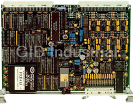
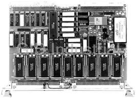
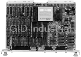
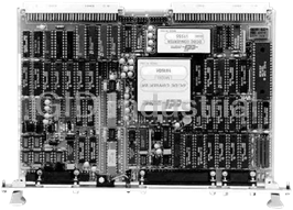
VMIC VME-3111 48 Analog-to-Digital Inputs | 2-Channel Digital-to-Analog Output Board
Part Number
VME-3111
Price
Request Quote
Manufacturer
VMIC
Lead Time
Request Quote
Category
Analog I/O
Features
- 12-bit Resolution
- 32-Channel SE/16 Differential P2 Connector Inputs
- 33 msec Conversion Time at Gain = x1 (Multiplexer Acquisition + A/D Conversion Time)
- A/D Data Coding Selectable as Either Binary, Offset Binary, or Two's Complement Format
- Allows Acquisition of Low-Level Input Signals: ±20 mV FSR to ±10 V FSR
- Analog Pipeline Mode (58 kHz Throughput at Gain = x1)
- Barrier Terminal Strips Available
- Compatible with VMIC Signal Conditioning Subsystems
- Compatible with VMIC's Family of Intelligent I/O Controllers (VMIVME-90XX Series)
- External Start Convert Capability
- Fail-Safe with Power Off
- Front Panel Inputs, 16-Channel, Single-Ended 3V/5V Compatible (Optional)
- Front Panel with Fail LED
- Full-Scale Input Range Options: 0 to +5 V, 0 to +10 V, ±2.5 V, ±5 V, ±10 V
- Optional Autozero and Autogain Calibration
- Optional Current Loop Termination Resistors Available for All Inputs
- Optional Low Pass Filters on All Inputs
- Optional On-Board Self-Test Voltage Standard
- Overvoltage Protected Inputs
- Programmable End-of-Conversion Interrupts
- Software Real-Time Programmable Gain 1, 10, 100, 500
- Supported by VMIVME/SW-9390 Universal I/O Driver (UIOD)
- System Error ±1 LSB
- Two Analog Outputs (12-bit) on P2 Connector Can Be Tested Off-Line
Datasheet

Extracted Text
VMIVME-3111 48 Analog-to-Digital Inputs 2-Channel Digital-to-Analog Output Boards • 32-channel SE/16 differential P2 connector inputs • Front panel inputs, 16-channel, single-ended — compatible with VMIC’s 3V/5V signal conditioning assemblies. This feature allows the VMIVME-3111 board to digitize the following input signals: low-level voltage, AC voltage, thermocouple, RTD, current, frequency, strain gauge, LVDT, and high-level voltage • Two analog outputs (12-bit) on P2 connector • 12-bit resolution • 27 ms conversion time at gain = x1 (multiplexer acquisition + A/D conversion time) — analog pipeline mode (53 kHz throughput at gain = x1) • Overvoltage protected inputs • Fail safe with power off • Software real-time programmable gain x1, x10, x100, x500 • Optional low pass filters on all inputs • Optional current loop termination resistors available for all inputs • Allows acquisition of low-level input signals: –20 mV FSR to –10 V FSR • Full-scale input range options: 0 to 5 V, 0 to +10 V, – 2.5 V, – 5 V, –10 V • A/D data coding program — selectable as either binary, offset binary, or two’s complement format • Programmable end-of-conversion interrupts • External start convert capability • Optional autozero and autogain calibration • Loopback test mode for Built-in-Test of all active components • Analog Outputs: To enable the user to close system Double Eurocard form factor with front panel and fail LED servo loops, analog outputs are available as two FUNCTIONAL CHARACTERISTICS independent, 12-bit channels. The outputs are multirange and are capable of supplying 10 mA at –10 Compliance: VMEbus specification Rev. C. 1 V. Both outputs can be monitored through the ADC for A16:D16:D08 (EO): 29, 2D: Slave Built-in-Test of all active components. Both analog Interrupter I(1) to I(7) ROAK (DYN):D08 (O)(DYN) outputs are disconnected from the P2 connector at power 6U form factor up. This allows the user to initialize the Board Address: The address for the board is selected Digital-to-Analog Converters (DACs) to the proper by on-board jumpers. This board can be plugged into voltage before enabling the outputs through the Control any available slot (except slot 1) in the backplane. Register. Address Modifier Codes: Jumper-selectable for short supervisory or short nonprivileged I/O access. Ordering Options December 5, 1993 800-003111-000 D Factory configured for short supervisory I/O access. ABC – D E F VMIVME-3111 – – VMEbus Reply: DTACK is generated from data A = Input Options strobes (DS0 or DS1) and the board address 0 = 32 Single-Ended or 16 Differential Inputs (P2 Connector) with No Front Panel Connector (P3) Data Conversion: Conversion may be initiated by 1 = Same as Above with Additional 16 Single-Ended Inputs Through Front Panel (P3) Connector. Connector Is program control or upon receipt of an externally 3V/5V Series Signal Conditioning Compatible. * generated pulse. Mode selection control is available to B = Filter Options (3 dB Attenuation) enable or disable the external trigger feature. Data 0 = No Filter or Terminators 1 = 6 Hz (3 dB Attenuation) conversion completion is determined by polling an 2 = 9 Hz (3 dB Attenuation) end-of-conversion bit in the Control and Status Register 3 = 36 Hz (3 dB Attenuation) 4 = Current Loop Terminator (250 W) (CSR) or by an interrupt to the processor. C = Autocal, Built-in-Test, and Analog Output Options 0 = No Autocal, No Auto Zero, No Built-in-Test, and No Analog Mode Selection: Operational modes of the board are Outputs selected by writing to the CSR with appropriate data bits 1 = Autocal, Auto Zero, Built-in-Test, and Two 12-bit D/A Analog Outputs set. * Call VMIC for further information concerning the 3V/5V Series signal conditioning assemblies. Analog Inputs: This product is designed to accept 32 Connector Data single-ended or 16 differential inputs through the user Connecting P2 (Panduit) P3 (3M I/O pins on the VMEbus P2 connector and 16 Scotchflex) Component single-ended inputs through the front panel P3 Compatible Mating Connector No. 120-964-455E 3399-6600 connector, giving a possible total of 48 input channels. Strain Relief No. 100-000-032 3448-3026 PC Board Header Connector Header Connector is on 3429-5002 The P3 connector is directly compatible with the Backplane VMIVME-3V and VMIVME-5V signal conditioning For Ordering Information, Call: assemblies. All inputs are available with optional low 1-800-322-3616 or 1-256-880-0444 • FAX (256) 882-0859 E-mail: info@vmic.com Web Address: www.vmic.com pass filters or with optional 250 W current loop Copyright © February 1987 by VMIC termination resistors. Specifications subject to change without notice. VMIC • 12090 South Memorial Parkway • Huntsville, Alabama 35803-3308 1 VMIVME-3111 Input Impedance: 10 MW (minimum) A 16-bit word location is reserved for each output channel. Data is transferred to each channel as a 12-bit, Input Zero Offset: Autocalibratable to ±50 mV (x500 right-justified (D11 to D00) word. gain) Autocalibration: Optional autocalibration provides Overvoltage Protection: ±40 V on-board adjustment of analog input zero and gain. Optional Single-Pole Filters: -3 dB at 6 Hz, 9 Hz, Correction values are accepted as 12-bit, right-justified ** 36 Hz data in two 16-bit locations. Analog Outputs: Self-Test Standards: Three precision on-board Resolution: 12 bits reference voltages (zero and ± full scale) are available for Built-in-Test and autocalibration. These voltages Analog Ranges: Jumper-selectable as 0 to +5 V, 0 to are routed via the analog configuration multiplexer for +10 V, ±2.5 V, ±5 V, ±10 V maximum accuracy. Monotonicity: Monotonic over full temperature range Converter Code: A jumper is provided for user Accuracy: ±0.03 percent selection of straight binary for unipolar inputs and offset binary and two’s complement for bipolar inputs. Settling Time: 25 ms, to 0.01 percent Data Transfer Type: D8, D16 Output Current: ±10 mA over full output range * ELECTRICAL CHARACTERISTICS Source Impedance: 0.2 W (maximum) Analog Inputs: Off-Line Leakage: 200 nA (maximum) Resolution: 12 bits Protection: Sustained shorts to ground; transients to Analog Ranges: Jumper-selectable as 0 to +5 V, 0 to ±40 V +10 V, ±2.5 V, ±5 V, and ±10 V Power Requirements: +5 V at 2.5 A (maximum) Gain: Program-selectable as x1, x10, x100, and x500 PHYSICAL/ENVIRONMENTAL A/D Conversion Time: 19 ms (sum of sample and conversion times) Dimensions: Standard VME double width board 160 x 233.5 mm Acquisition Time: Gain Input Settling VMEbus Connector: Two 96-pin DIN connectors x1 8 ms (P1 and P2) x10 20 ms Temperature: 0 to +55 °C, operating x100 50 ms -20 to +85 °C, storage x500 120 ms Humidity: 20 to 80 percent relative, noncondensing Throughput: 53 kHz (maximum) in pipelined mode SYSTEM THROUGHPUT — For sequentially Monotonicity: Monotonic over full temperature range switched multiplexer channels, each channel will be Common-Mode Range: ±[12.5 V - range/2] sampled at a rate of: (e.g., ±7.5 V on 10 V range) F = 1 samples per second, where S Common-Mode Rejection: 100 dB N(T1 + T2) Accuracy: N is the number of channels, Gain Percent FSR T1 is the multiplexer acquisition time, x1–0.03 T2 is the total A/D conversion time, which is the x10–0.08 sum of instrument amplifier settling time, the x100–0.13 sample-and-hold transient settling time, and x500–0.50 the A/D conversion time. ** Contact VMIC for special filter requirements. * Typical at 25 ˚C, unless specified otherwise. 2 For Ordering Information, Call: 1-800-322-3616 or 1-256-880-0444 • FAX (256) 882-0859 VMIVME-3111 For example, the throughput rate of 16 differential P2 cable connects the signal conditioning backplane to the inputs would be: front panel of the VMIVME-3111 ADC board. F = 1 = 2.315 kHz samples of each The 3V/5V series signal conditioning subsystem, in S conjunction with the VMIVME-3111 ADC board, provides 16 (8 ms + 19 ms) channel per second with a a complete solution enabling almost any type of sensor data gain of x1. to be available to the VMEbus. The following input INTERFACING TO VMIC’S 3V/5V SERIES modules are available: low level (mV), AC, thermocouple, SIGNAL CONDITIONERS — The 3V/5V series modular RTD, current, frequency, strain gage, LVDT, and high-level signal conditioners convert a wide variety of low-level (V) inputs. voltages, thermocouples, RTDs, etc., to high-level voltages. In addition, many of the modules provide up to TRADEMARKS –1,500 VRMS continuous isolation. Up to 16 of these The VMIC logo is a registered trademark of VMIC. modules may be installed in a signal conditioning backplane Other registered trademarks are the property of their with an optional 19-inch rack mount kit. The high-level respective owners. outputs are routed to a 26-pin connector, from which a ribbon APPLICATION AND CONFIGURATION GUIDES — The following Application and Configuration Guides are available to assist the user in configuring systems based on VMIC’s products. Title Document No. Digital Input Board Application Guide 825-000000-000 Change-of-State Board Application Guide 825-000000-002 Digital I/O (with Built-in-Test) Product Line Description 825-000000-003 Synchro/Resolver (Built-in-Test) Subsystem Configuration Guide 825-000000-004 Connector and I/O Cable Application Guide 825-000000-006 VMIC • 12090 South Memorial Parkway • Huntsville, Alabama 35803-3308 3 VMIVME-3111 – FULL-SCALE REF VOLTAGE AUTO CAL REFERENCE GAIN I/O CONN. STDS P2 LOW PASS ZERO FILTERS P2 OR CURRENT INPUT T&H 12-bit 12 DIFF PAIRS LOOP MULTIPLEXER PGA 16 DIFF AMP ADC RESISTORS HIGH/LOW SE PAIRS DIFF ANALOG 4 DIFF GAIN TRACK CONV CONV INPUTS PAIRS PSEUDO- CMD COMPL (32) DIFF RTN LOW 1 PAIR SELF-TEST MULTIPLEXER ANALOG 12 CONFIG ADC TIMING CONTROL I/O CONN LOW PASS SETTLING FILTERS P3 DELAY OR CURRENT P3 INPUT LOOP HIGH 15 MULTIPLEXER RESISTORS ANALOG 16 SE INPUTS (16) GND SENSE LOW 2 ANALOG CONTROL LOGIC PIN-COMPATIBLE WITH 3V AND BUS INTERRUPT 5V I/O CABLES ADC DATA LOGIC VME VMEbus INTERFACE OUTPUT MONITOR CONN. LOGIC I/O CONN. P1 2 (FEEDBACK) P2 DUAL 12-bit ANALOG D/A CONVERTER 2 ANALOG BUFFERS OUTPUTS AND SWITCHES (2) 2 VME 10 mA CONTROL ON-LINE/OFF-LINE BUS +5 V POWER–15 V CONVERTER Figure 1. VMIVME-3111 Functional Block Diagram 4 For Ordering Information, Call: 1-800-322-3616 or 1-256-880-0444 • FAX (256) 882-0859
Frequently asked questions
How does Industrial Trading differ from its competitors?

Is there a warranty for the VME-3111?
Which carrier will Industrial Trading use to ship my parts?
Can I buy parts from Industrial Trading if I am outside the USA?
Which payment methods does Industrial Trading accept?


What they say about us
FANTASTIC RESOURCE
One of our top priorities is maintaining our business with precision, and we are constantly looking for affiliates that can help us achieve our goal. With the aid of GID Industrial, our obsolete product management has never been more efficient. They have been a great resource to our company, and have quickly become a go-to supplier on our list!
Bucher Emhart Glass
EXCELLENT SERVICE
With our strict fundamentals and high expectations, we were surprised when we came across GID Industrial and their competitive pricing. When we approached them with our issue, they were incredibly confident in being able to provide us with a seamless solution at the best price for us. GID Industrial quickly understood our needs and provided us with excellent service, as well as fully tested product to ensure what we received would be the right fit for our company.
Fuji
HARD TO FIND A BETTER PROVIDER
Our company provides services to aid in the manufacture of technological products, such as semiconductors and flat panel displays, and often searching for distributors of obsolete product we require can waste time and money. Finding GID Industrial proved to be a great asset to our company, with cost effective solutions and superior knowledge on all of their materials, it’d be hard to find a better provider of obsolete or hard to find products.
Applied Materials
CONSISTENTLY DELIVERS QUALITY SOLUTIONS
Over the years, the equipment used in our company becomes discontinued, but they’re still of great use to us and our customers. Once these products are no longer available through the manufacturer, finding a reliable, quick supplier is a necessity, and luckily for us, GID Industrial has provided the most trustworthy, quality solutions to our obsolete component needs.
Nidec Vamco
TERRIFIC RESOURCE
This company has been a terrific help to us (I work for Trican Well Service) in sourcing the Micron Ram Memory we needed for our Siemens computers. Great service! And great pricing! I know when the product is shipping and when it will arrive, all the way through the ordering process.
Trican Well Service
GO TO SOURCE
When I can't find an obsolete part, I first call GID and they'll come up with my parts every time. Great customer service and follow up as well. Scott emails me from time to time to touch base and see if we're having trouble finding something.....which is often with our 25 yr old equipment.
ConAgra Foods