

 Manufacturers
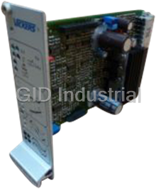
VICKERS EEA-PAM-535-D30

Description
AMPLIFIER
Part Number
EEA-PAM-535-D30
Price
Request Quote
Manufacturer
VICKERS
Lead Time
Request Quote
Category
None
Datasheet

Extracted Text
® Vickers Accessories Power Amplifiers with PID Modules EEA-PAM-5**-D-32 Series � Command input ramps – Closed-loop pressure control using General Description � Analog feedback sensor interface either proportional pressure valves or The EEA-PAM-5**-D-32 Eurocards are � Automatic switch-over p/Q function servo-performance proportional power amplifiers with integrated PID � Built-in test feature valves modules. Each of these cards replaces � The design reduces the amount of – Closed-loop velocity control two conventional electronic cards. external wiring, saves space in the rack – Closed-loop position control enclosure and requires only one 24V – p/Q control with internal or external Features and Benefits supply switch-over from Q to p � The general purpose, integrated � The DIL- switch and potentiometer � Includes all features of “A” amplifiers module can be configured using DIL settings can easily be reconfigured on (except gain) switches (D1-D9) and potentiometers different cards � User configurable PID feed-forward, for the following applications: closed-loop operation Front Panel LEDs [15] Mode switch [1] 24V power supply input, green – TEST VALVE setting – AUTO function setting [2] 15V control supply output, green AUTO 24/15 – TEST LOOP setting TEST TEST [3] Drive (solenoid) enabled, yellow [16] Test potentiometer VALVE LOOP [4] Overload, red 0 [5] LVDT failure, red � LEDs [6] Drive level to solenoid, yellow [17] PID-controller enabled, yellow –+ [18] Integrator enabled, yellow P Potentiometers [19] Feedback = command signal, green B [7] Deadband compensation, flow P to B � � [20] Sensor failure, red A [8] Deadband compensation, flow P to A � � Potentiometers LED [21] Feed-forward signal scaling [9] Ramps enabled, yellow V [22] P-gain Potentiometers P [23] I-gain t I [10] Command ramp up [24] D-gain t D [11] Command ramp down Monitor points � 1 3 5 Monitor points � [25] MP3: Command signal [12] MP1: Conditioned command signal [26] MP5: PID-controller output 2 4 6 [13] Common ground (0V) [27] MP6: Integrator output [14] MP2: LVDT (spool) position � [28] MP4: Feedback signal � Number and function of potentiometers [7], [8], [7.2] vary according to model type as follows: [7.2] Offset � LED and symbol not on EEA-PAM-513/523/525 amplifiers. � Solenoid current for EEA-PAM-523/525-D models. For models -513/541/553- � Ø2,0 mm (0.0787�dia.) sockets. � In the case of EEA-PAM-523/525-D models one of these relationships may not apply if two single solenoid valves are connected. This product has been designed and tested to meet specific standards outlined in the European Electromagnetic Compatibility Directive (EMC) 89/336/EEC, amended by 91/263/EEC, 92/31/EEC and 93/68/EEC, article 5. For instructions on installation requirements to achieve effective protection levels, see this leaflet and the Installation Wiring Practices for Vickers Electronic Products leaflet 2468. Wiring practices relevant to this Directive are indicated by Electromagnetic Compatibility (EMC) . January 1996 GB-2474 Model Codes Amplifier model For valves EEA-PAM-513-D-32 KCG-3, KCG-6/8 KX(C)G-6/8 EEA-PAM-523-D-32 K*G4V-3, KDG5V-5/7/8 With type “H” } coils only EEA-PAM-525-D-32 K*G4V-5 EEA-PAM-533-D-32 KF*G4V-3 EEA-PAM-535-D-32 KF*G4V-5 EEA-PAM-541-D-32 KHDG5V-5/7/8 with zerolapped mainspool EEA-PAM-553-D-32 KSDG4V-3 EEA-PAM-561-D-32 KFDG5V-5/7 EEA-PAM-568-D-32 KFDG5V-8 EEA-PAM-571-D-32 CVU-**-EFP1 EEA-PAM-581-D-32 KHDG5V-5/7/8 Operating Data Power (input) supply bz32 See appropriate base amplifier, e.g. for EEA-PAM-535-D-32 see EEA-PAM-535-A-32 Control (output) supplies z22 +15V for LVDTs only Reference voltages z2 +10V x 5 mA b2 –10V x 5 mA Analog inputs: Command inputs Direct-voltage inputs b6, b8, b10, z8 Inverting-voltage input z10 Voltage range �10V Input impedance (voltage) 47 kΩ Current input z6 Current range �20 mA Input impedance (current) 100Ω Feed-forward input d8 Input impedance 6 kΩ Voltage range �10V Input to ramp generator d28 Input impedance 10 kΩ Voltage range �10V Inputs from sensors Voltage input d2 Input impedance 1 MΩ Voltage range 0 to 10V, or �10V� Current input Input impedance 100Ω Current range (See “DIL Switches” five pages on) 4-20 mA or 0-20 mA Monitoring of sensor failure for sensors with a current outout only � The demand signal should have the same voltage range as the sensor feedback, Continued on next page i.e. 0 to 10V, or �10V. 2 Digital inputs: Drive enable (power available to solenoid) z24 Ramps enable b24 Integrator enable d14 Warning: In a power-up sequence, the integrator should not be enabled until all hydraulic, electric and control power and signals are applied and stable. Abrupt or unpredictable motion may occur if integrator is enabled during this transition time. PID-controller enable d12 Enabled 17 to 40V Disabled 0 to 3,5V Load current �10 mA Digital outputs: Sensor failure d18 Sensor failure Vcc –2V Sensor o.k. <3V Load current (withstands a continuous short-circuit condition) �100 mA This output may be used only in conjunction with sensors providing a current output (4-20 mA) Feedback = command signal d10 Feedback matches demand Vcc –2V Feedback does not match demand <3V Load current (withstands a continuous short-circuit condition) �100 mA The load at pin d18 and pin d10 has to be connected to ground Analog outputs: PID-controller output d4 Error signal d22 Feedback signal d24 Load impedance �10 kΩ; short-circuit proof Voltage range �10V Output from ramp generator d26 Load resistance �5 kΩ; short-circuit proof Voltage range �10V Alarm output (drive output status): z12 Set alarm Enable amplifier (on pin z24) >500 ms after switching power on. Signal HIGH when alarm is activated. Output = Supply volts minus 2 volts. I = 50 mA max. LOW when solenoid overload has occurred. (Maintained until reset). Output = 0 to +/–2 volts. Output resistance = 50 ohms. Reset after failure Disable and re-enable on pin z24. Ramp active indicator: b12 Drive ramping up Output >10V Drive ramping down Output <–10V Drive not ramping Output 0�10V Output resistance 10 kΩ Drive signal zero indicator: b20 Drive signal at null (within deadband limits) Output = Supply minus 1,5V; I = 50 mA max. Drive active Output = 0�2V Output resistance 50Ω Continued on next page 3 Potentiometers: Feed-forward V = 20% to 100% P-gain (depends on DIL switch D2): P = 0,1 to 50V/V I-gain range K = 0,5 to 100 V/s/V i D-gain range K = 0 to 0,05 V/V/s d Sensor signal gain range� 90% to 120% Sensor signal offset range� �10% Monitor points: Conditioned command signal MP1 LVDT (spool) position� MP2 Command signal MP3 Feedback signal MP4 PID-controller output MP5 Integrator output (100%, independent of D3, D4, D5) MP6 Voltage range �10V Monitor point impedance 10 kΩ Ambient conditions: Storage temperature range –25 to +85�C (–13 to +185�F) Operating temperature range 0 to 50�C (32 to 122�F) Mass 0,4 kg (0.88 lb) approx. Installation and start-up guidelines (supplied with product) 9161 Installation wiring requirements for Vickers electronic products 2468 Application notes (available on request) 9056 Supporting products: See catalogs: Power supply unit options 2419 Electronic accessories 2460 Portable test equipment 2462 and 2315 � Located on PID module. � All amplifiers except EEA-PAM-523/525 models, in which solenoid current is monitored. Warning: Electromagnetic Compatibility (EMC) It is necessary to ensure that the valve is wired up in accordance with the connection arrangements shown in this leaflet. For effective protection, the user’s electrical cabinet, the valve subplate or manifold and the cable screens should be connected to efficient earth (ground) points. The metal 7-pin connector part no. 934939 should be used for the integral amplifier. In all cases, both valve and cable should be kept as far away as possible from any source of electromagnetic radiation such as cables carrying heavy current, relays and certain kinds of portable radio transmitters, etc. Difficult environments could mean that extra screening may be necessary to avoid the interference. 4 Circuit and Connections EEA-PAM-5**-D-32 Read circuit in conjunction with that for relevant base amplifier EEA-PAM-5**-A z2 +10V 5 mA �15V 24V Power supply bz32 24V DC b2 –10V 5 mA Power bz30 +24V Power zero supply z24 Output enable +24V z12 Enable Close to enable Drive output z6 Dither status Current command signal Overload Deadband b6 compensation b8 z28 b10 z26 To solenoid Voltage Gain command z8 + Power signals z10 – amplifier b28 PWM Control zero bz4 To solenoid b26 Non-invert Solenoid D9 Ramp z22 current +15V z16 Connect to +10V (z2) b18 Inverter for p/Q control with z14 MP1 Pilot stage + automatic switch-over LVDT only – z22 LVDT +15V b12 Ramp active failure b16 b20 b14 Main stage LVDT b24 Ramp enable +24V z18 Close to enable MP2 Power amplifier PID control module d28 Feed d26 Test loop forward Valve. Actual connections V d8 see table on next page. Feed forward d12 D7 +24V Close to enable + Polarity PID- controller – d16 +10V Test valve Conditioned d24 feedback signal MP3 Gain Offset Sensor 0 to +10V P or sensor �10V d2 X + P-gain d4 U PID-controller output P d6 – Sensor 0 to 20 mA or sensor 4 to 20 mA 1-10% MP4 error PID- d18 controller Sensor failure MP5 enabled D-gain d10 Feedback = D D command signal Sensor failure D6 I MP6 Feedback = command signal I-gain + d22 Error signal I – D3 D5 d14 6% 50% +24V D4 Close to enable Integrator 35% integrator enabled Customer’s protective ground connection. 5 Solenoid and LVDT Connections for Proportional Valves Amplifier type Solenoid Solenoid Pilot-stage LVDT, Main-stage LVDT, with LVDT without LVDT, (black plug): (gray plug): and/or and/or f for or or or on p on pilot ilot Pin 1 Pin 2 Pin 3 Pin 4 Pin 1 Pin 2 Pin 3 Pin 4 flow P to B valve EEA-PAM-513-D-32 b26/b28 – – – – Not connected – – – Not connected EEA-PAM-523-D-32 b26/b28 z26/z28 – – – Not connected – – – Not connected EEA-PAM-525-D-32 b26/b28 z26/z28 – – – Not connected – – – Not connected EEA-PAM-533-D-32 b26/b28 z26/z28 – – – Not connected b14 z22 b16 Not connected EEA-PAM-535-D-32 b26/b28 z26/z28 – – – Not connected b14 z22 b16 Not connected EEA-PAM-541-D-32 – z26/z28 z14 z22 z16 Not connected b14 z22 b16 Not connected EEA-PAM-553-D-32 – z26/z28 – – – Not connected b14 z22 b16 Not connected EEA-PAM-561-D-32 – z26/z28 – – – Not connected b14 z22 b16 Not connected EEA-PAM-568-D-32 – z26/z28 – – – Not connected b14 z22 b16 Not connected EEA-PAM-571-D-32 – z26/z28 – – – Not connected b14 z22 b16 Not connected EEA-PAM-581-D-32 – z26/z28 z14 z22 z16 Not connected b14 z22 b16 Not connected Installation Dimensions in mm (inches) 3rd angle projection Plug-in Unit of 3U height, to IEC 297 DIN 41612 F48 male connector. Mating connector must be an 7,92 F48 female type. (0.31) z - pin row b - pin row d - pin row Components envelope M2,5 x 11 (0.43) long collar screws supplied with panel for fixing 2,5 (0.1) 122.4 (4.82) 128.4 100 (5.06) (3.94) Model designation 8 (0.31) 3 (0.12) 14,2 (0.56) 7,45 3 14 7,2 (0.29) (0.12) (0.55) (0.28) 50,3 175,24 (6.9) (1.98) 6 Application Notes DIL Switches 1 234 56 7 8 910 Location of User Features on The controller is configured for the PID Module ON application using DIL switches, located on OFF the board. Offset potentiometer Gain potentiometer Factory setting (sensor signal) (sensor signal) The DIL switch operates as follows: Switch ON OFF D1: For sensors with 4 to 20 mA output For sensors with �10V or 20 mA outputs Potentiometer D2: P-gain 2 to 50 P-gain 0,1 to 2 DIL In Position switches 1%-10% D6: One-sided limitation of the integrator No limitations of integrator output. (Only useful for proportional output Test point “P” pressure and proportional throttle P-gain valves.) D7: Inverts the controller output signal Non-inverted signal Test point “D” D8: For sensors with 4 to 20 mA output For sensors with �10V or D-gain 20 mA outputs Test point “I” Test point “V” D9: Ramp signal not inverted Ramp signal inverted I-gain Feed-forward gain D10: Not used – For p/Q control with automatic Reconfiguration of Controller switch-over, connect d16 to z2 (+10V). Parameters The flow command signal (Q) is applied to Once the controller parameters have the feed-forward input, d8, and the been optimized and set, they can be desired pressure setpoint voltage applied measured by means of an ohmmeter. to a command signal input (b6/8/10 or This allows easy reconfiguration of the z6/8/10). The pressure feedback sensor controller on different cards for use as is connected to the sensor input d2, or d6 spare parts or on standard machine as required. series. The pressure control loop will override the Four test points are located on the flow command to limit the pressure to the PID-module for this purpose, see diagram level determined by the pressure setpoint for locations. The resistance between the voltage. Adjust P, I and D gains for best appropriate test point and ground (at the performance. front panel monitor point) determines the controller parameters: The switches D3, D4 and D5 belong P = P-gain together. They limit the I output volts I = I-gain between 100% (10V) and 5% (0,5V) as D = D-gain follows: V = Feed-forward gain D3 D4 D5 l-limit ON ON ON 100% ON ON OFF 50% ON OFF ON 35% ON OFF OFF 25% OFF ON ON 5,9% OFF ON OFF 5,8% OFF OFF ON 5,3% OFF OFF OFF 5,0% 7 Test potentiometer Operation of the Integrated Test Mode on front panel The basic operation of the hydraulic actuator can be tested by using the 3-position mode switch mounted on the front panel. To select different modes the toggle switch must be lifted slightly To External before turning it to a new position. power command Controller amplifier signal Caution: Before setting the mode switch to either “Test valve” or “Test loop” make sure the TEST TEST test potentiometer is set to “0”. AUTO LOOP VALVE Otherwise sudden movements of the actuator may occur. Mode switch The mode switch has three positions: on front panel AUTO The controller operates in closed-loop mode, using the external command signal. The test potentiometer is disconnected. TEST VALVE An open-loop command signal for the valve comes directly from the potentiometer. The external input signal is disconnected. The hydraulic part of the system may be tested in this configuration. TEST LOOP The closed-loop command signal for the PID-controller comes directly from the potentiometer. The external signal input is disconnected. This configuration allows for verification of the valve polarity and the control parameters. � Eaton Hydraulics, Incorporated, 2000 Printed in U.S.A. All Rights Reserved
Frequently asked questions
How does Industrial Trading differ from its competitors?

Is there a warranty for the EEA-PAM-535-D30?
Which carrier will Industrial Trading use to ship my parts?
Can I buy parts from Industrial Trading if I am outside the USA?
Which payment methods does Industrial Trading accept?


What they say about us
FANTASTIC RESOURCE
One of our top priorities is maintaining our business with precision, and we are constantly looking for affiliates that can help us achieve our goal. With the aid of GID Industrial, our obsolete product management has never been more efficient. They have been a great resource to our company, and have quickly become a go-to supplier on our list!
Bucher Emhart Glass
EXCELLENT SERVICE
With our strict fundamentals and high expectations, we were surprised when we came across GID Industrial and their competitive pricing. When we approached them with our issue, they were incredibly confident in being able to provide us with a seamless solution at the best price for us. GID Industrial quickly understood our needs and provided us with excellent service, as well as fully tested product to ensure what we received would be the right fit for our company.
Fuji
HARD TO FIND A BETTER PROVIDER
Our company provides services to aid in the manufacture of technological products, such as semiconductors and flat panel displays, and often searching for distributors of obsolete product we require can waste time and money. Finding GID Industrial proved to be a great asset to our company, with cost effective solutions and superior knowledge on all of their materials, it’d be hard to find a better provider of obsolete or hard to find products.
Applied Materials
CONSISTENTLY DELIVERS QUALITY SOLUTIONS
Over the years, the equipment used in our company becomes discontinued, but they’re still of great use to us and our customers. Once these products are no longer available through the manufacturer, finding a reliable, quick supplier is a necessity, and luckily for us, GID Industrial has provided the most trustworthy, quality solutions to our obsolete component needs.
Nidec Vamco
TERRIFIC RESOURCE
This company has been a terrific help to us (I work for Trican Well Service) in sourcing the Micron Ram Memory we needed for our Siemens computers. Great service! And great pricing! I know when the product is shipping and when it will arrive, all the way through the ordering process.
Trican Well Service
GO TO SOURCE
When I can't find an obsolete part, I first call GID and they'll come up with my parts every time. Great customer service and follow up as well. Scott emails me from time to time to touch base and see if we're having trouble finding something.....which is often with our 25 yr old equipment.
ConAgra Foods