

 Manufacturers
SIEMENS 73N-B
Description
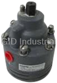
Siemens Moore 73NB Built-in Valve Positioner | Bottom Loading
Part Number
73N-B
Price
Request Quote
Manufacturer
SIEMENS
Lead Time
Request Quote
Category
Valve Positioner
Specifications
Air Consumption
0 6 SCFM (in balance condition with 20 psi supply and 9 psi dead ended output)
Ambient Temperature Limits
-40°C to +82°C (-40°F to +180°F)
Instrument Input Pressure Range
3-15, 3-9, 9-15, and 3-27 psi
Instrument Input Pressure, Maximum
15 psi for instrument input pressure spans of 12 psi or less and 27 psi
Response Level
0 25% of scale (Output sensitivity to input pressure changes)
Supply Pressure
Minimum: 3 psi above required actuator pressure. Maximum :100 psi
Valve Travel
Minimum : 1/4". Maximum :4"
Features
- Bottom Loading
- Built-in Valve Positioner
Datasheet

Extracted Text
Siemens INSTALLATION AND SERVICE INSTRUCTION Energy & Automation SD73B Rev 11 February 2006 Supersedes Iss. 10 MODEL 73N-B BUILT-IN VALVE POSITIONER BOTTOM LOADING The Model 73N-B is a bottom loading, built-in Valve Positioner which is mounted directly on the topworks of a valve. It is used on springless actuators that require a cushion load in the top of the actuator. The Model 73N-B1 is an optional configuration of the Model 73N-B. It is used on actuators that have an actuator range spring on top of the diaphragm or piston. The positioner is capable of utilizing the full force of its air supply to drive the actuator to a position called for by the control instrument. A single-axis force-balance principle of operation is incorporated in the positioner to insure accurate and stable positioning of a control valve. This makes it suitable for flow, temperature, pressure and numerous other control systems. Choose a calibrated range spring for the wide selection offered to accommodate almost any combination of valve stroke (1/4" to 4") and instrument span (2 to 24 PSIG). MODEL DESIGNATION 73N 12 B 1 Basic Model Number Input Span – psig Bottom Loading Positioner Optional Configuration for Actuators with Range Springs GENERAL SPECIFICATIONS Instrument Input Pressure Range...................3-15, 3-9, 9-15, and 3-27 psi Instrument Input Pressure, Maximum ...........15 psi for instrument input pressure spans of 12 psi or less and 27 psi for instrument pressure spans of 16 psi or greater Supply Pressure Minimum................................................3 psi above required actuator pressure Maximum...............................................100 psi Air Consumption ...........................................0.6 SCFM (in balance condition with 20 psi supply and 9 psi dead ended output) Valve Travel Minimum................................................1/4" Maximum...............................................4" Response Level..............................................0.25% of scale (Output sensitivity to input pressure changes) Ambient Temperature Limits ........................-40°C to +82°C (-40°F to +180°F) SD73B DESCRIPTION Model 73N-B The positioner is designed to operate a valve actuator to maintain the valve in a position determined by the control instrument. The positioner is direct acting, i.e., with an increase in instrument pressure, the valve pressure (positioner output) will increase. Because the output is connected to the bottom of the actuator, the valve stem will, in all cases, move toward the positioner when instrument pressure (positioner input) increases (see Figure 1). The actuator's actual position is fed back to the positioner, by the positioner range spring, as a force on the bottom of the positioner diaphragm assembly. The positioner pilot will continue to increase or decrease the positioner output until the force of the range spring balances the force created by the instrument pressure. The Model 73N-B is used on cushion loaded actuators. The cushion loading pressure is provided by an auxiliary regulator that is piped to the positioner LOAD connection. The cushion loading acts on the top of the actuator, providing the force to drive the actuator diaphragm or piston downward. Figure 1 Model 73N-B Figure 2 Model 73N-B1 Instrument pressure from the controlling device is connected to the INSTRUMENT port and is exerted between the middle and upper diaphragms of the positioner diaphragm assembly. Because of the difference In diaphragm areas, the resultant force is exerted in a downward direction. As the "instrument" pressure increases, the diaphragm assembly moves downward, the push-rod and valve spool move down, and supply air is admitted to the positioner output to increase the output (up to full supply pressure if necessary). The positioner output at the VALVE connection is admitted to the bottom of the actuator. As this "valve" pressure exceeds the cushion-load pressure, the actuator diaphragm or piston moves upward. This upward movement increases the force exerted by the positioner range spring on the positioner diaphragm assembly. When this force equals the force exerted by the "instrument" pressure, the supply is closed and the actuator remains in a balanced position. Conversely, with a decrease in "instrument" pressure, the air in the bottom of the actuator will exhaust through the positioner until the forces on the positioner diaphragm assembly are in balance. The cushion loading pressure acts both on the top of the actuator diaphragm or piston, and on the bottom of the positioner diaphragm assembly. This pressure must be admitted to the top of the positioner diaphragm assembly to neutralize its effect on the positioner diaphragm assembly. Otherwise, a pressure offset will occur. This is done by punching a hole through the bottom of the LOAD port to allow entry of the cushion loading pressure to the top of the positioner diaphragm assembly. For this configuration, the AUX. LOAD port is plugged. If an external "air failure" circuit is being used, the bottom of the LOAD port is not punched through. Instead, the cushion loading pressure, during normal operation, is common to both the LOAD and AUX. LOAD ports (see Figure 4). 2 SD73B During an air failure, the reserve capacity in the external "air failure" circuit continues to supply the cushion loading pressure to the positioner LOAD port. However, cushion loading to the AUX. LOAD is shut off. The cushion loading on top of the positioner diaphragm assembly bleeds past the push rod to the exhaust. This unbalances the positioner diaphragm assembly, causing it to move upward, which in turn moves the push rod and valve spool upward. The air in the bottom of the actuator is now exhausted through the positioner and the cushion loading moves the actuator downward. MODEL 73N-B1 The Model 73N-B1 (see Figure 2) is used on actuators that have an actuator range spring on top of the diaphragm or piston. Cushion loading and the optional "air failure" circuit are not used because of the actuator range spring. Since there is no cushion loading, the AUX. LOAD port is plugged and the LOAD port is vented. In addition, the bottom of the LOAD port is drilled through so that both the chamber above the actuator and the chamber above the positioner diaphragm assembly are vented to atmosphere. In all other respects, this positioner works the same as the Model 73N-B. The Model 73N-B1 is an optional configuration of the Model 73N-B. It is not available from stock as a 'B1. Instead, parts (Top Housing Assembly and Push Rod, see parts list) are shipped for the customer to make the conversion. An existing Model 73N-B in the field can be converted to a 'B1 by ordering and replacing the push rod, and by punching a hole through the bottom of the positioner LOAD port. INSTALLATION GENERAL These positioners are usually shipped to valve manufacturers who install them on their valves. Generally, the only task for the final user is to connect the supply, instrument and cushion loading lines. PREPARING THE MODEL 73N-B Decide if the positioner is to be used with or without an "air failure" circuit. If not, the bottom of the positioner LOAD port must be punched through. Use a center punch to open up a small hole at the base of the port (see Figure 7). MOUNTING THE POSITIONER Place the positioner range spring on the center of the actuator's diaphragm or piston. The diaphragm or piston should have a centering washer, etc., to fit the I.D. of the positioner range spring. This acts as a spring seat and keeps the spring from shifting. Place the positioner gasket on the mounting flange of the actuator top works. Place the positioner range spring seat on the center nut of the positioner diaphragm assembly. Hold the seat and guide the positioner and seat onto the range spring. Rotate the positioner so that Its VALVE port is oriented with respect to the actuator loading connection. Insert the six mounting screws and secure the positioner to the actuator's top works. PIPING Figure 3 shows the connections that must be made to the positioner. For a Model 73N-B1, the cushion loading line and regulator are omitted. Use 3/8" O.D. tubing (1/4" O.D. min.) for the SUPPLY and the positioner output (VALVE) to the actuator. 3 SD73B PNEUMATIC CONNECTIONS All connections are 1/4" N.P.T. Use 1/4" O.D. tubing for the instrument connection, either 1/4" or 3/8" O.D. tubing for all other connections. Blow out all piping before connections are made to prevent the possibility of dirt or chips entering the positioner. Use pipe sealant sparingly, and then only on the male threads. A non-hardening sealant is strongly recommended. Connect the positioner to a source of clean, dry, oil-free instrument air. See SUPPLY AIR REQUIREMENTS. CAUTION Pressure in excess of 150 psi to any connection may cause damage. A typical piping arrangement is shown in Figure 3. Figure 3 Piping Figure 4 Air Failure Circuit SUPPLY AIR REQUIREMENTS Connect the positioner to a source of clean, dry, oil-free supply air. Failure to do so will increase the possibility of a malfunction or deviation from specified performance. CAUTION Use of process fluids other than instrument air is not recommended. No claim is made as to the suitability of this product for use with other process fluids, such as hazardous gases, except as listed on the appropriate certificate. Non-approved instruments are suitable for use with instrument air only. Optional features and modifications such as tapped exhaust do not imply suitability for use with hazardous gases except as listed on the approval certificate. CAUTION Synthetic compressor lubricants in the air stream at the instrument may cause the positioner to fail. There are many types of synthetic lubricants. Some may not be compatible with the materials used in the construction of the positioner. Wetting of these materials by such an oil mist or oil vapor, etc., may cause them to deteriorate. This may ultimately result in failure of the positioner. The following materials are in contact with supply air: Aluminum, Brass, Stainless Steel, Neoprene and Buna-N. The requirements for a quality air supply can be found in the Instrument Society of America's "Quality Standard for Instrument Air" (ISA-S7.3). Basically this standard calls for the following: 4 SD73B Particle Size — Maximum particle size in the air stream should be no larger than 3 microns. Dew Point — Dew point at line pressure should be at least 10°C (18°F) below the minimum temperature to which any part of the instrument air system is exposed at any season of the year. Under no circumstances should the dew point at line pressure exceed 2°C (35.6°F). Oil Content — Maximum total oil or hydrocarbon content, exclusive of noncondensibles, should not exceed 1 ppm under normal operating conditions. CAUTION Exceeding the specified ambient temperature limits can adversely affect performance and may cause damage. CUSHION LOADING As a general rule of thumb, the cushion loading pressure is set at 50% of the supply pressure. If the valve or controlled mechanism places a considerable force on the actuator, the cushion loading pressure should be altered to compensate for it. Basically, what you are striving for is an equal split of forces to drive the actuator in either direction. The cushion loading pressure is properly set when a positioner output, equal to 50% of the supply pressure, just starts to move the actuator. AIR FAILURE CIRCUIT Figure 4 shows the components and connections required for an "air failure" circuit. This circuit applies only to Model 73N-B. During an air failure, this circuit will cause the actuator to move downward. The regulator used in this circuit must have soft supply and exhaust seats that provide a tight shut-off. ZERO ADJUSTMENT The only adjustment that can be made to the positioner is a zero adjustment. The zero adjusting screw is located under the positioner top cover. To adjust the zero, set the instrument air pressure to the midpoint of its span, and turn the zero adjustment until the valve is at the mid-point of its stroke. In some cases, valve shut-off or opening may be required at a specific instrument pressure. To zero the positioner at this point, set the instrument signal at the specific pressure and turn the zero adjustment screw until the valve reaches the required position. A slight change of the instrument pressure should start to move the valve. The valve stroke for a given span may also be suppressed or shifted to the desired range by means of the zero adjusting screw. 5 SD73B RANGE SPRING SELECTION Range springs for the positioner are selected from the table in Figure 5. Color coding of the range springs is given by the table in Figure 6. To find the proper spring, select the stroke listed which most nearly agrees with the desired stroke, and the pressure span which most nearly agrees with the desired span. The proper spring will be found at the intersection of these two columns. Series 4090 and 12395 range springs are available for stroke range tolerances of ±10%. Series 12388 range springs are available, at extra cost, for stroke range tolerances of ±5%. NOTE Maximum instrument input pressure for instrument input pressure spans of 12 psi or less is 15 psi; for instrument input pressure spans of 16 psi or greater it is 27 psi. MAINTENANCE GENERAL A clean, oil and moisture free air supply will reduce maintenance problems. The supply air filter should be blown down on a routine basis. The filter element should be examined periodically and replaced if necessary. No lubrication is required on the valve positioner. The system should be shut down or the valve isolated from the system before service or removal of the positioner is accomplished. CLEANING (Refer to parts list) The valve spool, sleeve and valve push rod can be cleaned without dismantling the positioner. Use the following procedure: 1. Turn off the supply air. 2. Remove the positioner top cover. 3. Remove the hex-head sealing screw. 4. Remove the valve spool and push rod. Use care so that they are not dropped. 5. Use a non-abrasive solvent to clean the parts. 6. Replace the push rod and valve spool. 7. Replace and tighten the hex-head sealing screw. 8. Replace the top cover. DISASSEMBLY (Refer to parts list) 1. Loosen the six socket head mounting screws holding the positioner to the actuator. 2. Remove the positioner. 3. Remove the two body screws holding the diaphragm stack assembly to the positioner body (located on the underside of the stack). 4. The diaphragm stack assembly can be further disassembled by removing the diaphragm jam nut. ASSEMBLY (Refer to parts list) To assemble, reverse the disassembly procedures. Take care to insure proper alignment of the diaphragms and rings. When tightening the jam nut on the diaphragm assembly, make sure the diaphragms do not rotate out of position. An alignment slot is provided on the rings to facilitate proper assembly. 6 SD73B * Special centering diaphragm PN 10636-59 is to be specified when range spring PN 12388-6412 or 12395-6412 is used. Range Spring Selection 1. In the table, find valve stroke nearest desired valve stroke. 2. In the table, find instrument input pressure span nearest desired instrument input pressure span. 3. Select proper range spring at intersection of valve stroke row and instrument input pressure span column. For additional information on range spring selection, request Application Bulleting AD73. Figure 5 Range Spring Index 7 SD73B Figure 6 Range and Zero Spring Color Codes 8 SD73B Figure 7 Installation Dimensions 9 SD73B PRODUCT SUPPORT This section provides the Internet site addresses, e-mail addresses, telephone numbers, and related information for customers to access Siemens product support. When contacting Siemens for support: • Please have complete product information at hand: • For hardware, this information is provided on the product nameplate (part number or model number, serial number, and/or version). • For most software, this information is given in the Help > About screen. • If there is a problem with product operation: • Is the problem intermittent or repeatable? What symptoms have been observed? • What steps, configuration changes, loop modifications, etc. were performed before the problem occurred? • What status messages, error messages, or LED indications are displayed? • What troubleshooting steps have been performed? • Is the installation environment (e.g. temperature, humidity) within the product’s specified operating parameters? For software, does the PC meet or exceed the minimum requirements (e.g. processor, memory, operating system)? • A copy of the product Service Instruction, User’s Manual, or other technical literature should be at hand. The Siemens public Internet site (see the table) has current revisions of technical literature, in Portable Document Format, for downloading. • To send an instrument to Siemens for repair, request a Return Material Authorization (RMA). IMPORTANT An instrument must be thoroughly cleaned (decontaminated) to remove any process materials, hazardous materials, or blood born pathogens prior to return for repair. Read and complete the Siemens RMA form(s). Contact Information Telephone +1 800 569 2132, option 2 for Siemens and Moore brand instruments Fax +1 215 646 3547 E-mail PITechSupp@sea.siemens.com United States Hours of Operation 8 a.m. to 4:45 p.m. eastern time of America Monday – Friday (except holidays) Public Internet Site www.sea.siemens.com/ia/ Repair Service +1 215 646 7400 extension 3187 For contact information outside the U.S.A., visit the Siemens public Internet site (see the above table for the URL), locate “Customer Support Process Instrumentation,” and click on the Contact Tech Support link to access the Global Support link. Current revisions of User’s Manuals for the listed controllers can be found at the Siemens public Internet site. The manuals are in Portable Document Format (PDF). 10 SD73B WARRANTY (a) Seller warrants that on the date of shipment the goods are of the kind and quality described herein and are free of non-conformities in workmanship and material. This warranty does not apply to goods delivered by Seller but manufactured by others. (b) Buyer's exclusive remedy for a nonconformity in any item of the goods shall be the repair or the replacement (at Seller's option) of the item and any affected part of the goods. Seller’s obligation to repair or replace shall be in effect for a period of one (1) year from initial operation of the goods but not more than eighteen (18) months from Seller’s shipment of the goods, provided Buyer has sent written notice within that period of time to Seller that the goods do not conform to the above warranty. Repaired and replacement parts shall be warranted for the remainder of the original period of notification set forth above, but in no event less than 12 months from repair or replacement. At its expense, Buyer shall remove and ship to Seller any such nonconforming items and shall reinstall the repaired or replaced parts. Buyer shall grant Seller access to the goods at all reasonable times in order for Seller to determine any nonconformity in the goods. Seller shall have the right of disposal of items replaced by it. If Seller is unable or unwilling to repair or replace, or if repair or replacement does not remedy the nonconformity, Seller and Buyer shall negotiate an equitable adjustment in the contract price, which may include a full refund of the contract price for the nonconforming goods. (c) SELLER HEREBY DISCLAIMS ALL OTHER WARRANTIES, EXPRESS OR IMPLIED, EXCEPT THAT OF TITLE. SPECIFICALLY, IT DISCLAIMS THE IMPLIED WARRANTIES OF MERCHANTABILITY, FITNESS FOR A PARTICULAR PURPOSE, COURSE OF DEALING AND USAGE OF TRADE. (d) Buyer and successors of Buyer are limited to the remedies specified in this article and shall have no others for a nonconformity in the goods. Buyer agrees that these remedies provide Buyer and its successors with a minimum adequate remedy and are their exclusive remedies, whether Buyer's or its successors’ remedies are based on contract, warranty, tort (including negligence), strict liability, indemnity, or any other legal theory, and whether arising out of warranties, representations, instructions, installations, or non- conformities from any cause. (e) Note: The above does not apply to any software which may be furnished by Seller. In such cases, the attached Software License Addendum applies. 11 SD73B PARTS LIST SIEMENS MODEL SERIES 73N_ _ B BOTTOM LOADING VALVE POSITIONER Drawing No. 7058PL 2/88 Supersedes 1/81 IMPORTANT Service Parts Kits are available for servicing the instrument. Contact Siemens for available kits; refer to the Product Support section of this instruction. Some parts in this Parts List may not be available for separate purchase. 12
Frequently asked questions
How does Industrial Trading differ from its competitors?

Is there a warranty for the 73N-B?
Which carrier will Industrial Trading use to ship my parts?
Can I buy parts from Industrial Trading if I am outside the USA?
Which payment methods does Industrial Trading accept?
Why buy from GID?

Quality
We are industry veterans who take pride in our work

Protection
Avoid the dangers of risky trading in the gray market

Access
Our network of suppliers is ready and at your disposal

Savings
Maintain legacy systems to prevent costly downtime

Speed
Time is of the essence, and we are respectful of yours
Related Products

Request a Quote

The quote request has been received
Close

Facing challenges or have inquiries? Feel free to contact us!
Call Us +1-469-283-2440
What they say about us
FANTASTIC RESOURCE
One of our top priorities is maintaining our business with precision, and we are constantly looking for affiliates that can help us achieve our goal. With the aid of GID Industrial, our obsolete product management has never been more efficient. They have been a great resource to our company, and have quickly become a go-to supplier on our list!
Bucher Emhart Glass
EXCELLENT SERVICE
With our strict fundamentals and high expectations, we were surprised when we came across GID Industrial and their competitive pricing. When we approached them with our issue, they were incredibly confident in being able to provide us with a seamless solution at the best price for us. GID Industrial quickly understood our needs and provided us with excellent service, as well as fully tested product to ensure what we received would be the right fit for our company.
Fuji
HARD TO FIND A BETTER PROVIDER
Our company provides services to aid in the manufacture of technological products, such as semiconductors and flat panel displays, and often searching for distributors of obsolete product we require can waste time and money. Finding GID Industrial proved to be a great asset to our company, with cost effective solutions and superior knowledge on all of their materials, it’d be hard to find a better provider of obsolete or hard to find products.
Applied Materials
CONSISTENTLY DELIVERS QUALITY SOLUTIONS
Over the years, the equipment used in our company becomes discontinued, but they’re still of great use to us and our customers. Once these products are no longer available through the manufacturer, finding a reliable, quick supplier is a necessity, and luckily for us, GID Industrial has provided the most trustworthy, quality solutions to our obsolete component needs.
Nidec Vamco
TERRIFIC RESOURCE
This company has been a terrific help to us (I work for Trican Well Service) in sourcing the Micron Ram Memory we needed for our Siemens computers. Great service! And great pricing! I know when the product is shipping and when it will arrive, all the way through the ordering process.
Trican Well Service
GO TO SOURCE
When I can't find an obsolete part, I first call GID and they'll come up with my parts every time. Great customer service and follow up as well. Scott emails me from time to time to touch base and see if we're having trouble finding something.....which is often with our 25 yr old equipment.
ConAgra Foods