

 Manufacturers
SCHNEIDER ELECTRIC XKBA15330

Description
Schneider Electric XKBA15330 Joystick. 30MM XKB +OPTIONS
Part Number
XKBA15330
Price
Request Quote
Manufacturer
SCHNEIDER ELECTRIC
Lead Time
Request Quote
Category
Joysticks
Datasheet

Extracted Text
Controllers and controller stations Types XK and XJ Catalogue October 04 Contents Controllers and controller stations b The range of controllers type XK, controller stations type XJ and application examples . . . . . . . . . . . . . . . . . . . . . . . . . . . . . . . . . . pages 2 and 3 Selection guide of controllers, types XD and XK . . . . . . . . . . . . . pages 4 and 5 Selection guide of controller stations and desks, type XJ . . . . . pages 6 and 7 Controllers b For hoisting applications, type XK, terminology . . . . . . . . . . . . . . pages 8 and 9 b For “light hoisting” applications, type XKB . . . . . . . . . . . . . . . . . . pages 10 to 17 b For “medium hoisting” applications, type XKD . . . . . . . . . . . . . . . pages 18 to 25 b For “heavy hoisting” applications, type XKM . . . . . . . . . . . . . . . . . pages 26 to 39 b Dimensions . . . . . . . . . . . . . . . . . . . . . . . . . . . . . . . . . . . . . . . . . . pages 40 to 43 Potentiometers for controllers b For standard applications, type XKZ A . . . . . . . . . . . . . . . . . . . . . . . . . . . page 44 b For applications requiring an extended “neutral zone”, types XKB Z and XKD Z . . . . . . . . . . . . . . . . . . . . . . . . . . . . . . . . . . . . . . page 45 Controllers stations and desks b Presentation . . . . . . . . . . . . . . . . . . . . . . . . . . . . . . . . . . . . . . . . pages 46 and 47 b Type XJP A for controllers XKB and Ø 22 mm pushbuttons, switches and pilot lights . . . . . . . . . . . . . pages 48 and 49 b Type XJ9 BA for controllers XKB and Ø 22 mm or 30 mm pushbuttons, switches and pilot lights . . . . . pages 50 and 51 b Dimensions . . . . . . . . . . . . . . . . . . . . . . . . . . . . . . . . . . . . . . . . . pages 52 and 53 Fixed controller desk b Type XJC C . . . . . . . . . . . . . . . . . . . . . . . . . . . . . . . . . . . . . . . . . . . . . . . . page 54 Fixed or rotating controller desks b Types XJC D and XJC E. . . . . . . . . . . . . . . . . . . . . . . . . . . . . . . . pages 55 to 60 b Dimensions . . . . . . . . . . . . . . . . . . . . . . . . . . . . . . . . . . . . . . . . . . . . . . . . page 61 1 Presentation 1 Controllers and controller stations1 The range of controllers type XK and controller stations type XJ Controllers XKB For “light hoisting” applications Controllers XKD For “medium hoisting” applications Controllers XKM For “heavy hoisting” applications Portable controller stations XJP and XJ9 For “heavy hoisting” applications Fixed or rotating controller desks XJC For “heavy hoisting” applications 2 Presentation 1 Controllers and controller stations1 Application examples Public works cranes, stocking, materials handling, etc. Public works cranes Cranes, overhead travelling cranes (iron and steelworks, rolling mills, etc.) Overhead travelling cranes Public works cranes 3 Selection guide 1 Controllers 1 For hoisting applications, types XD and XK Applications “Light hoisting” Compact and lightweight For control of small materials For control of materials handling equipment, public handling equipment, elevating work cranes, etc. work platforms, fork-lift trucks, Can be installed on portable controller stations etc. type XJP Can be installed on control panels or enclosures types XAL, XAM and XAP Mechanical durability 1 in each direction 1 in each direction 1 in each direction (in millions of operating cycles) Number of Basic 2 or 4 depending on model 4 4 directions Variable composition – 8 8 Number of movements 1 or 2 2 2 Maximum number of notches in each direction XD2: 1 or 2 3 3 XD4, XD5: 1 Types of lever Notched with stayput operation b b b movement with spring return to b b b zero operation Unnotched with spring return to – b b zero operation Operating schemes Predefined cams Predefined cams Variable composition cams Maximum number of contacts per movement XD2: 4 (1 or 2 N/O contacts in 4 or 4 + 1 zero (centre) 4 or 4 + 1 zero (centre) each direction) position contact position contact XD4, XD5: 2 (1 N/O contact in each direction) Contact (1) Supply a and c a and c a and c Nominal thermal current 10 A 10 A 10 A Mechanical durability of contact blocks 5 1 1 (in millions of operating cycles) Control device Vertical lever Vertical lever Vertical lever Handles (2) a simple b b b b1 with zero (centre) position – b b mechanical interlocking b2 with zero (centre) position – b b mechanical and electrical interlocking c1 “Dead man’s” type – b b c2 with built-in pushbutton – b b Lever gate Fixed composition Variable composition Variable composition 30° in each direction Maximum number of potentiometers per movement – 1 or 2 depending on contact 1 or 2 depending on contact block arrangement blocks arrangement Type references XD2, XD4, XD5 XKB A XKB E Page(s) Please refer to our "Human- 12 14 Machine interfaces" catalogue (1) N/C slow break contacts with positive opening operation. Contacts closed in absence of cam lobe. (2) Handles type b1 and b2 are designed in accordance with the French hoisting standard NF E 52070 (Dec. 1985): Electrical equipment of hoisting devices, paragraph 8231: all control devices must be designed, constructed and positioned in such a manner as to avoid any accidental operation… 4 1 1 “Medium hoisting” “Heavy hoisting” Compact and fully configurable unit Extremely robust and fully configurable unit For control of cranes, overhead For control of overhead travelling cranes (iron and steelworks, rolling mills) etc. travelling cranes, etc. Can be installed on seated controller desks type XJC Can be installed on fixed seated controller desks type XJC 3 in each direction 4 in each direction 4 in each direction 4 in each direction 4 4 2 2 8 8 2 2 2 2 1 1 5 6 6 9 b b b b b b b b b b b b Variable composition cams Variable composition cams Variable composition cams Variable composition cams 16 24 24 12 a and c a and c a and c a and c 10 A 20 A 20 A 20 A 3 4 4 4 Vertical lever Vertical lever Vertical lever Side lever b b b b b b b – b b b – b b b – b b b – Predefined or customised Predefined or customised – – 2 2 2 1 B XKD F XKM A XKM B XKM C 20 28 28 34 5 Selection guide (continued) 1 Controller stations and desks 1 For hoisting applications, type XJ Applications “Heavy hoisting” Portable controller stations For remote control of overhead travelling cranes Model Portable Yes With harness, protective guards and chest frame, depending on model Fixed – Associated controller type XKB XJP A5: 2 controllers type XKB fitted with – 4-contact blocks per movement, with or without potentiometers XJP A6: 2 controllers type XKB fitted with 4-contact blocks per movement + 1 zero (centre) position contact, with or without potentiometers XKD – 2 controllers type XKD F with or without potentiometers XKM – – Other components Ø 22 mm pushbuttons, switches and pilot Ø 22 mm pushbuttons, switches and pilot lights: up to 8 units lights: 1 to 7 units depending on model Ø 30 mm pushbuttons, switches and pilot lights: 1 to 5 units depending on model Material Glass-reinforced polyester Colour: yellow Type of seat – Dimensions 430 x 150 x 230 (see page 52) XJ9 BA1: 480 x 255 x 395 XJ9 BA2: 605 x 258 x 645 (see page 53) Weights v Empty with cable boot: 2 kg XJ9 BA1: v Fitted: approximately 4 kg v Empty with cable boot: 3.5 kg v Fitted: approximately 7.5 kg XJ9 BA2: v Empty with cable boot: 4.5 kg v Fitted: approximately 8.5 kg Type references XJP Ap XJ9 BAp Page(s) 48 and 49 50 and 51 6 1 1 “Heavy hoisting” Fixed or rotating seated controller desks For control of cranes, overhead travelling cranes (iron and steelworks, rolling mills, etc.) – Fixed to the floor Fixed to the floor Fixed to the floor Seat + enclosures rotating assembly (friction bearing) – 1 controller type XKD maximum on each enclosure, with or without potentiometers 1 controller type XKM maximum on each enclosure, 1 or 2 controllers type XKM depending on width of enclosure, with or without potentiometers with or without potentiometers – Ø 22 mm or Ø 30 mm pushbuttons, switches and pilot lights Up to 22 units, depending on enclosures selected Steel “High comfort” seat, with armrests and headrest, depending on model Helical spring suspension with double-action hydraulic shock absorbers 1100 x 630 x 1180 mm (see page 61) 1360 x 610 x 1170 mm (see page 61) Enclosures: 300 x 225 x 500 mm Enclosures: width 250 to 430 mm Customisable mounting (see pages 56 to 60) 55 kg without equipment XJC Cp XJC Dp XJC Ep 54 55 55 7 Terminology 1 Controllers 1 For hoisting applications, type XK Controller The controllers are units designed to control hoisting and materials handling equipment by grouping their electrical circuits. They comprise adaptable sub-assemblies that enable the construction of many different versions. Used in association with automation system equipment, they ensure the starting, acceleration and braking of the drive motors. They are designed for fitting into portable controller stations or controller desks. The mounting is dust and damp protected. Mechanical block Articulated mechanical assembly that holds the control lever, lever gate, actuating mechanism, cam carriers, contacts and potentiometer adaptation device. Control lever Operating device that enables separate or simultaneous control of the movements. Fitted to it are dust and damp protecting bellows, the handle and mechanical and electrical safety devices that are actuated when the controller lever is returned to its zero (centre) position. Lever gate 2 types of lever gate: b Standard types: Standard lever gates v universal: allows the lever to move to its maximum travel in 1 or 2 directions simultaneously (“universal” or “8-direction” controller), v “cross” or “I” gates: only allow the lever to move to its maximum travel in 1 direction at a time. b Special types: related to the application, they are used to control the required 18˚12˚ 6˚ 0˚ 6˚ 12˚18˚ universal “cross” “I” combination of movements. Examples of special lever gates End stops Additional devices for limiting the lever travel to a number of positions in a given direction. Handles a Simple handle: fixed knob screwed onto the control lever. b1 Handle with zero (centre) position mechanical interlock. Operation: The knob of the handle comprises a fixed part (upper section) and a moving part (lower section). When the lever is in the zero (centre) position, it is mechanically locked by a sliding rod within the lever. To disengage the lock, the lower part of the handle is pulled upwards thus freeing the rod. b2 Handle with zero (centre) position mechanical interlock + electrical contact. Mechanical operation identical to that described above. When the lever is in the zero (centre) position, the rod actuates a contact block. The disengagement of the lock causes the contact(s) in the block to change state. a b1 b2 c1 “Dead man’s” handle. Operation: The knob of the handle comprises a fixed part (lower section) and a moving part (upper section). When the upper section of the knob is pushed downwards it pushes a sliding rod within the lever. This rod actuates a moving bowl which, in turn, causes a contact block (located in the lower part of the mechanism) to change state and remain in this condition irrespective of the control lever position. c2 Handle with built-in flush or projecting pushbutton (audible alarm type). Mechanical operation identical to that described above. The handle is fixed and it is only the pushbutton that operates the sliding rod. c1 c2 8 Terminology (continued) 1 Controllers 1 For hoisting applications, type XK Direction This is the direction of operation of the control lever away from its zero (centre) position towards one of 2 or 4 directions (either 2 directions directly in line or 4 A A directions at 90°). Diagonal movement is the operation of 2 directions simultaneously. DC C B B B B+C 2 directions 4 directions 2 directions simultaneously Movement The movement is the combination of 2 directions either side of the zero position that are directly in line. A A DC C B B 2 movements 1 movement AB AB and CD Electrical position This is the change of state of a contact block obtained by angular displacement of the control lever. Types of lever movement Three different types of lever operation for each direction: 1 Notched positions, with stayput operation. 01 2 n The control lever is moved notch by notch from its zero (centre) position to its maximum travel position in the required direction. The lever maintains its position when the operator releases the handle. 1 2 Notched positions, with spring return to zero operation. Notched operation identical to that described above but with an automatic device that returns the lever to its zero (centre) position when the operator releases the handle. 2 3 Unnotched positions, with spring return to zero operation. The control lever of the controller is moved from its zero (centre) position to its maximum travel position in the required direction without notching. Irrespective of its position, the lever spring returns to the zero (centre) position when 3 the operator releases the handle. Electrical contacts When designing the scheme take into account that all contacts are closed until actuated (opened) by an operating cam. Cam schemes The contact blocks are actuated by a series of various length cams which are arranged to provide the required scheme. Electrical scheme in accordance with IEC 113-4 These cams can either be: n 4 3 2 1 0 1 2 3 4 n v variable composition, i.e. comprising different sub-assemblies mounted on a cam 1 carrier, 2 v predetermined, i.e. for a function that is widely used in conventional schemes. 3 4 Example: reversing cams for direction of operation. Controller scheme in accordance with IEC 337-2A Cam carriers n 4 3 211 0 234n 1 Mechanism designed for mounting cams on for controllers with variable composition 2 cams. 3 4 Cam actuation of contacts When actuated by the cam lobe, the contact opens thus ensuring positive opening operation. Therefore, the presence of a cam corresponds to the absence of a cross or line on the scheme. 1 Example of graphic representation of a scheme 2 The various methods for indicating the operating sequence of the contacts are represented by schemes in accordance with IEC 113-4 or IEC 337-2A (section 2). The ordering grids for XK controllers are designed in accordance with IEC 337-2A 3 (section 2). Take particular note of the way an assured electrical overlapping is represented as is shown for contacts 2 and 4 between positions 2 and 3 (see diagram to left). 4 n… 24˚ 18˚ 12˚ 6˚ 0˚ 6˚ 12˚ 18˚ 24˚ n… Operating cycle An operating cycle applied from an initial common O position is the passing from this initial position to the extreme position in each direction and subsequent return to the A initial O position. DC 0 B 9 Presentation 1 Controllers 1 For “light hoisting” applications, type XKB Compact and lightweight units, designed to control “light hoisting” and materials handling equipment. Mainly for use in portable stations. 2 models: b XKB A: controllers with predefined, non modifiable, scheme. b XKB E: controllers with variable composition schemes. Control lever Length: 130 mm. Travel in each direction: 28° maximum. Lever gate Universal and modifiable. Specific, by adding half-gates to the universal lever gate (referenced by letter) 9 main combinations. . End stops The total lever travel can be limited to 20° or 12° by using removable end stops (XKB Z972 for 20°, XKB Z971 for 12°) when the lever gate comprises half-gates Y or Z. XKB p Handles b Simple handle with zero (centre) position contact (closed at zero). b Handle with zero (centre) position mechanical interlock + contact (closed at zero). b “Dead man’s” handle with contact (open when handle released). S T U V b Handle with built-in flush or projecting pushbutton and contact (open when 1 2 2 3 pushbutton or handle released). 2 2 3 1 Note: it is important to decide which type of handle is required when selecting the controller, since modification cannot be affected after installation. 1 1 2 1 Electrical positions W X Y Z 3 positions maximum in each direction. 3 3 3 3 3 3 3 3 Types of lever movement b Notched positions, with stayput operation: 3 notches maximum in each 2 3 3 1/2 Half-gates direction (12°, 20°, 28°). b Notched positions, with spring return to zero operation: 3 notches maximum in each direction (12°, 20°, 28°). (XKB E: only 1 contact may be used at each notch.) S + S T + T U + U V + V b Unnotched positions, with spring return to zero operation: 28° maximum travel in each direction. (XKB E: only 1 contact may be used for each spring return to zero position.) Contacts The contact blocks used for establishing the scheme are located in a monobloc assembly. There are 2 types: W + W X + X Y + Y Z + Z v Block with 4 contacts per movement. v Block with 4 contacts per movement + 1 zero (centre) position contact. For both types, an additional contact is available. Its function depends on the type of handle. Cam schemes Z + Y b XKB A: standard schemes can be established using predefined cams. These cams are moulded and cannot be modified. 2 versions: v Using a block with 4 contacts per movement: 2 reversing cams and 2 function cams per movement. v Using a block with 4 contacts per movement + 1 zero (centre) position contact: 9 main combinations 2 reversing cams and 2 function cams per movement + 1 zero (centre) position cam. b XKB E: special schemes can be established using snap-on cams (for each position) mounted on cam carriers. (overlapping contact operation is not possible). 2 versions: v Using a block with 4 contacts per movement: 4 variable composition cams per movement. v Using a block with 4 contacts per movement + 1 zero (centre) position contact: 4 variable composition cams per movement + 1 fixed composition zero (centre) position cam. Legend One 100 x 100 mm anodised aluminium legend plate with matt satin finish. Standard “hoist-long travel” and “traverse-slew” symbols or text (to be stated on Order form, see page 13). Potentiometer adaptation b 2 potentiometers maximum per movement when using block with 4 contacts per movement. b 1 potentiometer maximum per movement when using block with 4 contacts per movement + 1 zero (centre) position contact. Characteristics: Order form: Dimensions: page 11 pages 13 and 14 page 40 10 109229-34_M Characteristics 1 Controllers 1 For “light hoisting” applications, type XKB Environment Conformity to standards IEC 337-1, NF C 63-140, VDE 0660 part 2 Product certifications XKB A: CSA a 300 V “heavy duty”, c “standard duty”, ASE: 500 mV max., 10 A max., 100 VA max., USSR Protective treatment Standard version “TC” Ambient air temperature For storage °C - 40…+ 70 For operation °C - 20…+ 70 Operating position All positions Vibration resistance 6 gn (1 to 70 Hz) Shock resistance Conforming to IEC 68-2-27 20 gn, duration 11 ms Electric shock protection Conforming to IEC 536 and Class I NF C 20-030 Maximum operating lever force daN < 1.7 required in each direction Degree of protection Conforming to IEC 529 IP 54 (unit with simple handle mounted in dust and damp proof enclosure) Mechanical durability 1 in each direction (In millions of operating cycles) Weight kg XKB A and XKB E: z 0.850 Contact block characteristics Type Monobloc assembly comprising 9 double-break contacts (8 function contacts and 1 zero position contact mounted at lever base) or monobloc assembly comprising 11 double-break contacts (8 function contacts + 2 zero position contacts and 1 zero position contact mounted at lever base) Conventional thermal current A 10 conforming to IEC 337-1, NF C 63-140, VDE 0660, CSA C 22-2 n° 14 Rated insulation voltage V z 500 conforming to NF C 20-040, VDE 0110, IEC 158-1 Insulation category Group C conforming to NF C 20-040 and VDE 0110 Contact operation Slow break, double-break contacts with positive opening operation; N/O (green operator). N/C contact (red operator): zero position contact mounted at lever base Resistance across terminals mΩ y 25 (in accordance with NF C 93-050, at 1 A) Terminal referencing Conforming to CENELEC EN 50013 Short-circuit protection 10 A cartridge fuse type gG conforming to IEC 337-1B, VDE 0660 part 2 Operational power a.c. supply a 50-60 Hz d.c. supply c Conforming to IEC 337-1 o Inductive circuit Utilisation categories AC-11 and DC-11 Operating rate: 3600 operating cycles/hour 5 Power broken in W for 1 million operating Load factor: 0.5 cycles Voltage V 24 48 120 380 V 220 V 127 V 2 o 90 90 75 48 V 1 500 V 0,5 0,1 0,4 1 5 10 20 Current (A) Connection Captive screw clamp terminals Clamping capacity: 2 v minimum 1 x 0.5 mm , 2 2 v maximum, with or without cable end: 2 x 1.5 mm or 1 x 2.5 mm , or by clips conforming to NF C 20-120 Order form: Dimensions: pages 12 to 15 page 40 11 Millions of operating cycles Referencing grid 1 Controllers 1 For “light hoisting” applications, types XKB A and XKB E Grid for composing the reference of a controller Reference of controller type XKB Model Contacts Handle Lever Potentiometer movement adaptation AB CD XKB Model With predefined scheme A With variable composition scheme E Contact blocks Block with 4 contacts per Screw clamp terminal connections 1 movement 6.3 clip connections 2 Block with 4 contacts per movement Screw clamp terminal connections 3 + 1 zero (centre) position contact 6.3 clip connections 4 Handle Simple + zero (centre) position electrical interlocking (contact closed in rest position) 1 With zero (centre) position mechanical and electrical interlocking (contact closed in rest position) 2 “Dead man’s” type (contact open when released) 4 With built-in flush pushbutton (contact open in rest position) 5 With built-in projecting pushbutton (contact open in rest position) 6 Type of lever movement On movement AB Movement not required (blocked) 0 Notched positions, with stayput operation 1 Unnotched positions, with spring return to zero operation 2 Notched positions, with spring return to zero operation (1) 3 On movement CD Movement not required (blocked) 0 Notched positions, with stayput operation 1 Unnotched positions, with spring return to zero operation 2 Notched positions, with spring return to zero operation (1) 3 Potentiometer adaptation Without adaptation nor potentiometer 0 Adaptation only (without On movement AB 4 potentiometer) On movement CD 5 On movements AB + CD 6 Adaptation + potentiometer (2) On movement AB 7 On movement CD 8 On movements AB + CD 9 (1) Type of lever operation recommended when using a potentiometer. (2) Potentiometer type and value to be stated on the Order form. For standard application potentiometers, see page 44. Characteristics: Dimensions: page 11 page 40 12 Order form Controllers 1 For “light hoisting” applications, type XKB A (specimen suitable for Controllers XKB A with predefined, non modifiable photocopying) 1 schemes, factory assembled See example on page 15 Schneider Electric Industries Customer Company Customer’s reference Sales office - Subsid. - Plant Editor Geographical zone Order N° Reference (use the grid for composing the reference of a controller on page 12) Model Contacts Handle Lever movement Potentiometer adaptation AB CD Number of identical units XKB A For Schneider Electric Industries use only Order N° Item N° MOD ETI POI GLV CTS MAB MCD PAB PCD XKB Lever gate Potentiometer adaptation In accordance with the half-gates available, sketch and Cross v the required position on the schemes below. crosshatch the lever’s field of movement on the scheme grids On movement AB Type/size: below. Value: In the absence of this information, the controller will be On movement CD Type/size: supplied with a “universal” gate. Value: Legend Without legend With blank legend XKB Y1 With “traverse-slew” symbols, XKB Y2 With “hoist-long travel” symbols, XKB Y3 With specific engraved text, XKB Y1001 (clearly state the text on the scheme below) Left-hand operated unit Right-hand operated unit Scheme 1: 4 contacts per movement (viewed from above) Scheme 2: 4 contacts + 1 zero (centre) position contact per movement (viewed from above) Orientation locater Orientation locater Movement CD Movement CD Adaptation Potentiometer 103 104 Item (1) Item (1) 83 93 84 94 73 83 74 84 Direction D Direction C Direction D Direction C 0 0 Text: Text: Direction A Direction A 28˚ 20˚ 12˚ 12˚ 20˚ 28˚ 28˚ 20˚ 12˚ 12˚ 20˚ 28˚ Direction B Direction B Text: Text: Contact at Contact at 0 0 Direction D Direction C Direction D Direction C lever base lever base Item (1) Item (1) 74 64 63 73 54 53 64 Item (1) 63 Item (1) Adaptation Potentiometer Adaptation Potentiometer Movement CD Movement CD (1) Reserved for contact identification in the automation system scheme. It is not possible to mark it on the controller. Characteristics: Dimensions: page 11 page 40 13 Movement AB Adaptation Potentiometer 13 14 Item (1) 23 24 Direction B 0 Direction A Text: Direction D 28˚ 20˚ 12˚ 12˚ 20˚ 28˚ Direction C Text: 0 Direction A Direction B 33 34 43 44 Adaptation Potentiometer Movement AB Movement AB 53 54 43 44 Item (1) 33 34 Direction B Direction A 0 Text: Direction D 28˚ 20˚ 12˚ 12˚ 20˚ 28˚ Direction C Text: 0 Direction B Direction A 23 24 13 14 Adaptation Potentiometer Movement AB Order form Controllers 1 For “light hoisting” applications, type XKB E (specimen suitable for Controllers XKB E with variable and modifiable photocopying) 1 schemes, factory assembled Schneider Electric Industries Customer Company Customer’s reference Sales office - Subsid. - Plant Editor Geographical zone Order N° Reference (use the grid for composing the reference of a controller on page 12) Model Contacts Handle Lever movement Potentiometer adaptation AB CD Number of identical units XKB E For Schneider Electric Industries use only Order N° Item N° MOD ETI POI GLV CTS MAB MCD PAB PCD XKB Lever gate Potentiometer adaptation In accordance with the half-gates available, sketch and Cross v the required position on the schemes below. crosshatch the lever’s field of movement on the scheme grids On movement AB Type/size: below. Value: In the absence of this information, the controller will be On movement CD Type/size: supplied with a “universal” gate. Value: Legend Without legend With blank legend, XKB Y1 With “traverse-slew” symbols, XKB Y2 With “hoist-long travel” symbols, XKB Y3 With specific engraved text, XKB Y1001 (clearly state the text on the scheme below) Left-hand operated unit d If the scheme is not defined, all XKB E controllers will be supplied with the standard scheme Right-hand operated unit as used for XKB A. Scheme 1: 4 contacts per movement (viewed from above) Scheme 2: 4 contacts + 1 zero (centre) position contact per movement (viewed from above) Orientation locater Orientation locater Movement CD Movement CD Adaptation Potentiometer 104 103 Item (1) Item (1) 84 83 94 93 74 73 84 83 Direction D 0 Direction C Direction D 0 Direction C Text: Text: Direction A Direction A 28˚ 20˚ 12˚ 12˚ 20˚ 28˚ 28˚ 20˚ 12˚ 12˚ 20˚ 28˚ Direction B Direction B Text: Text: Contact at Contact at 0 0 Direction D Direction C Direction D Direction C lever base lever base Item (1) Item (1) 64 74 63 73 54 64 53 63 Item (1) Item (1) Adaptation Potentiometer Adaptation Potentiometer Movement CD Movement CD (1) Reserved for contact identification in the automation system scheme. It is not possible to mark it on the controller. Spring return operation: only 1 contact can be used with spring return at each notch. 14 Movement AB Adaptation Potentiometer 13 14 Item (1) 23 24 Direction A Direction B 0 Text: Direction D 28˚ 20˚ 12˚ 12˚ 20˚ 28˚ Direction C Text: Direction B 0 Direction A 33 34 43 44 Adaptation Potentiometer Movement AB Movement AB 54 53 44 43 Item (1) 33 34 Direction B Direction A 0 Text: Direction D 28˚ 20˚ 12˚ 12˚ 20˚ 28˚ Direction C Text: Direction A Direction B 0 23 24 13 14 Adaptation Potentiometer Movement AB Order form example 1 Controllers 1 For “light hoisting” applications, type XKB E Ordering form completion example Composition of the reference (see page 12) Requirement A 2 movement controller: “hoist-long travel”. E 3 4 2 3 7 XKB “Universal” lever gate, limited to 2 “lower” positions. Model With variable composition scheme (customised electrical E scheme as shown below) Contact blocks Block with 4 contacts + 1 zero (centre) position contact per 3 movement (screw clamp terminals). Handle “Dead man’s” type 4 Type of lever operation on movement AB Unnotched positions, with spring return to zero operation 2 Type of lever operation on movement CD Notched positions, with spring return to zero operation 3 Potentiometer adaptation With adaptation device + potentiometer on movement AB, standard 4700 Ω, size 15, model 7 Electrical scheme for movement AB “hoist” Electrical scheme for movement CD “long travel” 3 2 1 0 1 2 3 3 2 1 0 1 2 3 Hoist zero position Reverse Lower Forward Raise S2 L.HS S3 R.HS (Reverse) (Forward) (Raise) + Potentiometer (Lower) Lever gate Potentiometer adaptation In accordance with the half-gates available, sketch and Cross v the required position on the schemes below. crosshatch the lever’s field of movement on the scheme grids On movement AB Type/size: below. Value: In the absence of this information, the controller will be On movement CD Type/size: supplied with a “universal” gate. Value: Legend Without legend With specific engraved text, XKB Y1001 (clearly state the text on the scheme below) With blank legend, XKB Y1 Left-hand operated unit With “traverse-slew” symbols, XKB Y2 Right-hand operated unit With “hoist-long travel” symbols, XKB Y3 d If the scheme is not defined, all XKB E controllers will be supplied with the standard scheme as used for XKB A. Scheme 1: 4 contacts per movement (viewed from above) Scheme 2: 4 contacts + 1 zero (centre) position contact per movement Orientation locater Orientation locater Movement CD Movement CD Adaptation Potentiometer Item (1) Item (1) Direction D Direction C Direction D Direction C Text: Text: Direction A Direction A Direction B Direction B Text: Text: Contact at Contact at Direction D Direction C Direction D Direction C lever base lever base Item (1) Item (1) Item (1) Item (1) Adaptation Potentiometer Adaptation Potentiometer Movement CD Movement CD (1) Reserved for contact identification in the automation system scheme. It is not possible to mark it on the controller. Spring return operation: only 1 contact can be used with spring return at each notch. 15 Movement AB Adaptation Potentiometer Item (1) Direction B Direction A Text: Direction D Direction C Text: Direction B Direction A Adaptation Potentiometer Movement AB Movement AB Item (1) Direction A Direction B Text: Direction D Direction C Text: Direction B Direction A Adaptation Potentiometer Movement AB Presentation 1 Controllers 1 For “light hoisting” applications, type XKB Separate components XKB Z913 XKB Z914 XKB Z915 1 XKB Z916 XKB Z917 XKB Y1 XKB Y2 12 XKB Y3 XKB Y1001 2 XKB Z921 XKB Z971 3 XKB Z972 XKB Z901 XKB Z902 XKB Z903 XKB Z904 4 XKB Z905 XKB Z906 XKB Z975 11 XKB Z907 XKB Z976 XKB Z908 XKB Z977 10 XKB Z978 XKB Z979 5 XKB Z952 XKB Z981 9 6 XKB Z953 XKB Z982 XKZ A15 XKB Z962 XKZ A18 7 XKB Z964 XKB Z15 XKB Z966 XKB Z18 8 XKB Z992 XKB Z994 16 References 1 Controllers 1 For “light hoisting” applications, type XKB Separate components Description Item Characteristics Unit reference Weight kg Bellows 2 – XKB Z921 0.060 Handles 1 Simple XKB Z913 0.030 d Not interchangeable between different models With zero (centre) position interlocking XKB Z914 0.040 “Dead man’s” type XKB Z915 0.045 With built-in flush pushbutton XKB Z916 0.030 XKB Z913 With built-in projecting pushbutton XKB Z917 0.030 Lever gate 4 S XKB Z901 0.005 Universal and modifiable T XKB Z902 0.005 XKB Z915 Specific, by adding half-gates to the U XKB Z903 0.005 universal lever gate (referenced by letter) V XKB Z904 0.005 W XKB Z905 0.005 XKB Z914 X XKB Z906 0.005 Y XKB Z907 0.005 Z XKB Z908 0.005 Removable end stops 3 Stop limiting to 1 notch of movement XKB Z971 0.025 Sold in lots of 10 Stop limiting to 2 notches of movement XKB Z972 0.020 Contacts: block with 4 contacts per 8 For use with simple handle or handle with XKB Z962 0.185 movement zero (centre) position interlocking Screw clamp terminal connections For use with “Dead man’s” handle or XKB Z966 0.185 handle with built-in pushbutton Contacts: block with 4 contacts per 8 For use with simple handle or handle with XKB Z992 0.215 movement + 1 zero (centre) position zero (centre) position interlocking contact For use with “Dead man’s” handle or XKB Z994 0.215 Screw clamp terminal connections handle with built-in pushbutton XKB Z916 XKB Z917 Cam carriers for variable composition 11 – XKB Z975 0.105 cams (XKB E only) Sold in lots of 20 Cams 10 Right-hand position (colour: green) XKB Z976 0.010 (XKB E only) XKB Z972 XKB Z971 Sold in lots of 50 Left-hand position (colour: red) XKB Z977 0.010 S T U 1 2 2 Pass cam (colour: black) XKB Z978 0.010 2 2 1 Zero (centre) position cam 5 – XKB Z979 0.010 with fixing screw 1 1 2 Lever base adaptations 9 Interlocking bowl XKB Z952 0.010 V W X 3 3 3 Bowl for “Dead man’s” handle or handle XKB Z953 0.010 3 3 3 with built-in pushbutton Legends 12 Blank XKB Y1 0.025 1 2 3 W X Y “Traverse - slew” XKB Y2 0.025 3 3 3 “Hoist - long travel” XKB Y3 0.025 3 3 3 With specific engraved text XKB Y1001 0.025 2 3 3 Z Potentiometer adaptation kits (1) 6 Size 15 XKB Z981 0.090 3 3 Size 18 (2) XKB Z982 0.090 1/2 Potentiometers for controllers XKB 7 – XKZ A15pp, A18pp – XKB Z15pp, Z18pp See pages 44 and 45 (1) Including 13 tooth pinion. v The maximum lever travel of 28° per direction corresponds to a potentiometer shaft rotation of 161°. v Levers with friction drive facility are available under certain conditions: please consult your Regional Sales Office. (2) The size 18 potentiometer adaptation on an XKB controller prevents it from being mounted in an XJP controller station. XKB Y2 XKB Y3 17 Presentation 1 Controllers 1 For “medium hoisting” applications, type XKD Compact and fully configurable units designed to control “medium hoisting” equipment. Mainly for use on fixed control stations or seated controller desks type XJC. 1 model: b XKD F: controller with variable composition schemes. Control lever Length: 200 mm. Travel in each direction: 36° maximum. Lever gate Integral, non removable, part of the mechanical block. Must be specified on the Order form. Handles b Simple handle. b Handle with zero (centre) position mechanical interlock. b Handle with zero (centre) position mechanical interlock + 1 C/O snap action contact. b “Dead man’s” handle + slow break contact(s). b Handle with built-in flush or projecting pushbutton + slow break contact(s). Angular electrical positions b 6 positions maximum in each direction. XKD F Types of lever movement b Notched positions, with stayput operation 2 versions: v 5 notches maximum in each direction, at 12°, 18°, 24°, 30° and 36° (6° per notch), only when used with variable composition cam carriers comprising 4 or 8-contact st blocks (1 notch at 6°). v 3 notches maximum in each direction, at 12°, 24° and 36° (12° per notch), only when used with variable composition cam carriers comprising 2-contact blocks. Note: It is possible to use, on the same movement, a “5 notch max.” cam carrier combined with a “3 notch max.” cam carrier. The lever operation is “5 notch” type. b Notched positions, with spring return to zero operation 3 or 5 notches maximum in each direction depending on the versions stated above. st d 4 simultaneous contacts max. with spring return can be used at the 1 (12°) notch. b Unnotched positions, with spring return to zero operation 36° maximum travel in each direction. d 2 simultaneous contacts maximum with spring return can be used at 6° and then 4 contacts maximum at each subsequent 6° position. Contacts 16 contacts maximum per movement. The contact blocks are mounted in pairs on a fixing plate. Cam schemes 2 versions: b Variable composition cams, 6° per position; 4 or 8-contact cam carriers. v From 1 to 5 mechanical positions. v Overlapping contact operation possible (see graphic representation on page 9) th except between the 4 and last position. b Variable composition cams, 12° per position; 2-contact cam carriers. v From 1 to 3 mechanical positions. v The contacts can be actuated 6° by 6° approx., except under the following conditions: For technical reasons, it is essential to have at least 3 spaces on the electrical scheme for the same contact. 2 possible examples 2 impossible examples 0 0 11 12 11 12 12 22 12 22 3 spaces minimum The 2-contact cam carriers are compact and do not increase the size of the mechanical block base. Legend One 120 x 120 mm anodised aluminium legend plate with matt satin finish. Text to be stated on Order form. Potentiometer adaptation 2 potentiometers maximum per movement: v mounted directly on the mechanical block when used with 2-contact variable composition cams, v mounted at the extremity of the contact supports when used with 4 and 8-contact variable composition cams. Order form: Dimensions: pages 20 and 21 page 41 18 109230-34- Characteristics 1 Controllers 1 For “medium hoisting” applications, type XKD Environment Conformity to standards IEC 337-1, NF C 63-140, VDE 0660 part 2 Product certifications CSA A600, Q 600, Bureau Véritas, USSR Protective treatment Standard version “TC” Ambient air temperature For storage °C - 40…+ 70 For operation °C - 20…+ 70 Operating position All positions Vibration resistance 2 gn (10 to 500 Hz) conforming to IEC 68-2-6 Shock resistance 15 gn, duration 11 ms, conforming to IEC 68-2-27 Electric shock protection Class I, conforming to IEC 536 and NF C 20-030 Maximum operating lever force daN Notched positions, with stayput operation: Notched or unnotched positions, with required in each direction < 1.5 spring return to zero operation: < 3.5 Degree of protection IP 54 conforming to IEC 529 (unit with simple handle mounted in dust and damp proof enclosure) Mechanical durability In millions of operating cycles XKD F: 3 in each direction Weight XKD F kg Mechanical block: 0.950 4-contact assembly: 0.350 8-contact assembly: 0.560 Contact block characteristics Type N/C contact (ZB2 BE102) Conventional thermal current A 10 conforming to IEC 337-1, NF C 63-140, VDE 0660, CSA C 22-2 n° 14 Rated insulation voltage V z 500 conforming to NF C 20-040, VDE 0110, IEC 158-1 Insulation category Group C conforming to NF C 20-040 and VDE 0110 Contact operation Slow break, double-break contacts with positive opening operation Resistance across terminals mΩ y 25 (in accordance with NF C 93-050, at 1 A) Short-circuit protection 10 A cartridge fuse type gG conforming to IEC 337-1B, VDE 0660 part 2 Operational power a.c. supply a 50-60 Hz d.c. supply c Conforming to IEC 337-1 o Inductive circuit Utilisation categories AC-11 and DC-11 Power broken in W for 1 million operating Operating rate: 3600 operating cycles/hour cycles Load factor: 0.5 Voltage V 24 48 120 o 65 48 40 1 0,5 12/48 V 500 V 0,1 127 V 0,05 220 V 380 V 0,01 0,1 0,5 1 5 10 50 Current (A) Connection Captive screw clamp terminals Clamping capacity: 2 v minimum 1 x 0.5 mm , 2 2 v maximum, with or without cable end: 2 x 1.5 mm or 1 x 2.5 mm conforming to NF C 20-120 Order form: Dimensions: pages 20 and 21 page 41 19 Millions of operating cycles Referencing grid 1 Controllers 1 For “medium hoisting” applications, type XKD F Grid for composing the reference of a controller Reference of controller type XKD Movement AB Movement CD Lever Handle No. of Lever Potentiometer No. of Lever Potentiometer blocks movement adaptation blocks movement adaptation XKD F 1 Control lever Standard model, length 200 mm 1 Handle Simple (standard model) 1 With zero (centre) position mechanical interlocking 2 With zero (centre) position mechanical & electrical interlocking (1 C/O contact) 3 “Dead man’s” type With N/C + N/O contact 4 With N/O + N/O contact 5 With built-in flush With N/C + N/O contact 6 pushbutton With N/O + N/O contact 7 With built-in projecting With N/C + N/O contact 8 pushbutton With N/O + N/O contact 9 Movement AB Number of 2-contact blocks 0 blocks 0 1 block 1 2 blocks 2 3 blocks 3 4 blocks 4 5 blocks 5 6 blocks 6 8 blocks 8 Type of lever movement Notched positions, with stayput 3 notches (1) 1 operation 5 notches (starting from 12°) or 6 notches (from 6°) (2) (3) 2 Notched positions, with spring 3 notches (1) 3 return to zero operation 5 notches (starting from 12°) or 6 notches (from 6°) (2) (3) 4 Unnotched positions, with spring return to zero operation (4) 5 Potentiometer adaptation Without adaptation nor potentiometer 0 With adaptation only (without potentiometer) 1 With adaptation + potentiometer (5) 2 Movement CD Number of 2-contact blocks 0 blocks 0 1 block 1 2 blocks 2 3 blocks 3 4 blocks 4 5 blocks 5 6 blocks 6 8 blocks 8 Type of lever movement Notched positions, with stayput 3 notches (1) 1 operation 5 notches (starting from 12°) or 6 notches (starting from 6°) (2) (3) 2 Notched positions, with spring 3 notches (1) 3 return to zero operation 5 notches (starting from 12°) or 6 notches (starting from 6°) (2) (3) 4 Unnotched positions, with spring return to zero operation (4) 5 Potentiometer adaptation Without adaptation nor potentiometer 0 With adaptation only (6) (without potentiometer) 1 With adaptation (6) + potentiometer (5) 2 (1) 3 notches: restricted to 2-contact variable composition cams only. st (2) 5 notches: by using 1 or 2 variable composition 4 or 8-contact cams. 1 mechanical notch at 12° (6 electrical positions in each direction). st (3) It is possible to obtain 6 mechanical notches, 1 mechanical notch at 6° (6 electrical positions in each direction). Please consult your Regional Sales office. (4) Type of lever operation recommended when using a potentiometer. (5) Potentiometer type and value to be stated on the Order form, see pages 44 and 45. st (6) It is possible to obtain 6 mechanical notches, 1 mechanical notch at 6° (6 electrical positions in each direction). Please consult your Regional Sales office. Characteristics: Dimensions: page 19 page 41 20 Order form Controllers 1 For “medium hoisting” applications, type XKD F (specimen suitable for Controllers with variable composition schemes, photocopying) 1 factory assembled See example on page 23 Customer Schneider Electric Industries Company Customer’s reference Sales office - Subsid. - Plant Editor Geographical zone Order N° Reference (use the grid for composing the reference of a controller on page 20) Movement AB Movement CD Lever Handle No. of Lever Potentiometer No. of Lever Potentiometer blocks movement adaptation blocks movement adaptation Number of identical units XKD F 1 For Schneider Electric Industries use only Order N° Item N° MOD LEV POI GLV CT1 CT3 MAB P13 CT2 CT4 MCD P24 XKD Drum Lever gate Movement CD Potentiometer adaptation n°2 Sketch and crosshatch the lever’s field Adaptation Potentiometer Cross J the position on the scheme of movement on the grid 82 81 On movement AB 72 71 Type/size: 62 61 52 51 Value: 42 41 (c) On movement CD 32 31 22 21 Type/size: (b) 12 11 Value: 22 21 12 11 Item (2) Item (2) (a) 0 Direction D Direction C Text: Ex: 5 notches Direction A 36˚ 30˚ 24˚ 18˚ 12˚ 6˚ 12˚ 18˚ 24˚ 30˚ 36˚ 12˚ 24˚ 36˚ Direction B Ex: 3 notches Text: (a) (b) (b) (a) Direction D Direction C 0 (a) (c) (c) 11 12 Choice of cam carriers (1) Choice of cam carriers (1) 21 22 Choice of cam carriers Legend 11 12 (1) Cross J the type of cam carrier required: Without legend 21 22 (a): 3 notch cam carrier, 2 contacts max., 31 32 Blank legend XKB Y1 (b) (b): 5 notch cam carrier, 4 contacts max., 41 42 Legend with specific (c): 5 notch cam carrier, 8 contacts max. 51 52 engraving, XKD Y1001 (c) (2) Reserved for contact identification in the 61 62 (clearly state text on this scheme) automation system scheme. It is not 71 72 Left-hand operated unit possible to mark it on the controller. 81 82 Contact at lever base Adaptation Potentiometer Drum Right-hand operated unit Movement CD n°4 Item (2) th th b Electrical overlapping of contacts is not possible between the 5 and 6 notches. b Spring return operation: 2 simultaneous contacts maximum with spring return can be used at 6° and then 4 contacts at each subsequent 6° position. 21 Drum Movement AB n°3 Adaptation Potentiometer 82 81 72 71 62 61 52 51 42 41 32 31 22 21 12 11 22 21 Choice of cam carriers (1) 12 11 Direction B Direction A 0 Text: Direction D Ex: 6 notches 36˚ 30˚ 24˚ 18˚ 12˚ 6˚ 6˚ 12˚ 18˚ 24˚ 30˚ 36˚ Direction C Text: 0 Direction B Direction A Item (2) Item (2) 11 12 21 22 11 12 21 22 31 32 41 42 51 52 61 62 71 72 81 82 Adaptation Potentiometer Drum Movement AB n°1 Referencing grid 1 Controllers 1 For “medium hoisting” applications, type XKD F Controller selection example Requirement A 2 movement controller: “hoist-traverse”. “Cross” type lever gate. Controller conforming to NF E 52-070. No potentiometer adaptation on movements AB or CD. Scheme for movement AB “hoist” Scheme for movement CD “traverse” 5 4 3 2 1 0 1 2 3 4 5 3 2 1 0 1 2 3 Raise Left Lower Right R4 L4 LS 2 RS 2 R3 L3 LS 3 RS 3 R2 L2 Zero R1 L1 (Left) (Right) Zero (Raise) (Lower) Notes: Movement AB The scheme for movement AB requires 7 contacts, therefore, select 4 blocks of 2 contacts. The only alternative is the selection of either drum n° 3 or n° 1, depending on the available space. Movement CD The space between each notch indicated on the 3 position scheme cannot be adhered to. Effectively, to obtain 5 contacts, a 2-contact block can be selected (drum n° 2), which does not increase the size of the base, together with 2 x 2-contact blocks (drum n° 4). The lever gate will limit the lever travel to 3 notches. Composition of the reference (see page 20) XKD F 1 2 4 4 0 3 4 0 Control lever Standard, length 200 mm 1 Handle With zero (centre) position mechanical interlocking 2 Movement AB “hoist” Number of 2-contact blocks 4 blocks 4 Type of lever movement 5 notched positions, with spring return to zero operation 4 Potentiometer adaptation Without adaptation nor potentiometer 0 Movement CD “traverse” Number of 2-contact blocks 3 blocks 3 Type of lever movement 5 notched positions, with spring return to zero operation 4 Potentiometer adaptation Without adaptation nor potentiometer 0 Order form: Characteristics: Dimensions: pages 20 and 21 page 19 page 41 22 Order form example 1 Controllers 1 For “medium hoisting” applications, type XKD F Ordering form completion example Customer Schneider Electric Industries Company Customer’s reference Sales office - Subsid. - Plant Editor Geographical zone Order N° Reference (use the grid for composing the reference of a controller on page 20) Movement AB Movement CD Lever Handle No. of Lever Potentiometer No. of Lever Potentiometer blocks movement adaptation blocks movement adaptation Number of identical units XKD F For Schneider Electric Industries use only MOD LEV POI GLV CT1 CT3 MAB P13 CT2 CT4 MCD P24 Order N° Item N° XKD Scheme: viewed from above Drum Lever gate Potentiometer adaptation Movement CD n°2 Sketch and crosshatch the lever’s field Cross J the position on the scheme Adaptation Potentiometer of movement on the grid 82 81 On movement AB 72 71 Type/size: 62 61 52 51 Value: 42 41 (c) On movement CD 32 31 22 21 Type/size: (b) 12 11 Value: 22 21 12 11 Item (2) Item (2) (a) Direction D 0 Direction C Text: Ex: 5 notches Direction A 36˚ 30˚ 24˚ 18˚ 12˚ 6˚ 12˚ 18˚ 24˚ 30˚ 36˚ 12˚ 24˚ 36˚ Direction B Ex: 3 notches Text: (b) (a) (b) (a) 0 Direction D Direction C (a) (c) (c) 11 12 Choice of cam carriers (1) Choice of cam carriers (1) 21 22 Choice of cam carriers Legend 11 12 (1) Cross J the type of cam carrier required: Without legend 21 22 (a): 3 notch cam carrier, 2 contacts max., 31 32 Blank legend XKB Y1 (b) (b): 5 notch cam carrier, 4 contacts max., 41 42 Legend with specific (c): 5 notch cam carrier, 8 contacts max. 51 52 engraving, XKD Y1001 (2) Reserved for contact identification in the (c) 61 62 (clearly state text on this scheme) automation system scheme. It is not 71 72 Left-hand operated unit possible to mark it on the controller. 81 82 Contact at lever base Right-hand operated unit Adaptation Potentiometer Drum Movement CD n°4 Item (2) th th b Electrical overlapping of contacts is not possible between the 5 and 6 notches. b Spring return operation: 2 simultaneous contacts maximum with spring return can be used at 6° and then 4 contacts at each subsequent 6° position. 23 Drum Movement AB n°3 Adaptation Potentiometer 82 81 72 71 62 61 52 51 42 41 32 31 22 21 12 11 22 21 Choice of cam carriers (1) 12 11 Choice of cam carriers (1) Direction B 0 Direction A Text: Ex: 6 notches Direction D 36˚ 30˚ 24˚ 18˚ 12˚ 6˚ 6˚ 12˚ 18˚ 24˚ 30˚ 36˚ Direction C Text: 0 Direction B Direction A Item (2) 11 12 21 22 11 12 21 22 31 32 41 42 51 52 61 62 71 72 81 82 Adaptation Potentiometer Drum Movement AB n°1 Presentation 1 Controllers 1 For “medium hoisting” applications, type XKD F Separate components XKD Z913 XKD Z914 1 XKD Z915 XKD Z916 XKD Z917 2 XKD Z921 XKZ A15 XKD Y1 XKZ A18 12 3 XKD Y1001 XKD Z15 XKD Z18 XKD Z905 11 XKD Z981 4 XKD Z982 XKD Z960 XKD Z961 XKD Z950 XKD Z963 XKD Z951 XKD Z964 10 XKD Z952 XKD Z965 XKD Z953 XKD Z966 XKD Z954 5 XKD Z967 XKD Z955 XKD Z956 XKD Z957 XKD Z958 XKD Z901 8 XKD Z909 9 XKD Z902 8 XKD Z983 6 XES B1011 XKD Z984 ZB2 BE101 7 ZB2 BE102 24 References 1 Controllers 1 For “medium hoisting” applications, type XKD F Separate components Description Item Characteristics Unit reference Weight kg Bellows 2 Bellows + 1 flat seal XKD Z921 0.075 Handles 1 Simple XKD Z913 0.060 d Not interchangeable between different With zero (centre) position interlocking XKD Z914 0.035 models “Dead man’s” type XKD Z915 0.040 XKD Z913 With built-in flush pushbutton XKD Z916 0.050 With built-in projecting pushbutton XKD Z917 0.050 Spring return operation mechanism 11 Spring return to zero mechanism XKD Z905 0.100 Sold in lots of 2 XKD Z914 Notched operation mechanism 9 Position notching mechanism for variable XKD Z909 0.010 composition cams Variable composition cams for 5 Pass cam XKD Z950 0.005 support with 4 or 8 contacts Complementary, 1 position XKD Z951 0.005 Sold in lots of 50 Complementary, 1.5 position XKD Z952 0.010 Complementary, 2 positions XKD Z953 0.010 Complementary, 3 positions XKD Z954 0.020 Complementary, 6 positions XKD Z955 0.035 5 positions XKD Z956 0.030 7 positions XKD Z957 0.040 9 positions XKD Z958 0.050 XKD Z915 XKD Z916 Variable composition cams for 10 Complementary, half-position XKD Z960 0.005 support with 2 contacts Complementary, 1 position XKD Z961 0.005 Sold in lots of 20 Reversing, for notches 1+ 2 + 3 XKD Z963 0.020 Acceleration, for notches 2 + 3 XKD Z964 0.005 Acceleration, for notch 3 XKD Z965 0.010 Pass cam XKD Z966 0.010 Cam for zero position contact XKD Z967 0.010 Scheme contacts 8 2 x ZB2 BE102 contacts Without marker XKD Z901 0.050 mounted on baseplate With marker XKD Z902 0.050 Zero (centre) position electrical 7 Snap action XES B1011 0.030 interlocking C/O contact XKD Z917 Contacts for “Dead man’s” handle or 7 Slow break N/C, positive ZB2 BE102 0.015 handle with built-in pushbutton opening N/O ZB2 BE101 0.015 Legends 12 Blank XKD Y1 0.035 With specific engraved text XKD Y1001 0.035 Potentiometer adaptation kits 4 On end of contact Size 15 XKD Z981 0.120 (1) supports Size 18 XKD Z982 0.130 6 Directly on mechanical Size 15 XKD Z983 0.120 block Size 18 XKD Z984 0.130 Potentiometers for controllers XKD 3 – XKZ A15pp, A18pp – XKD Z15pp, Z18pp See pages 44 and 45 (1) Including 15 tooth pinion. v The maximum lever travel of 36° per direction corresponds to a potentiometer shaft rotation of 168°. v Levers with friction drive facility are available under certain conditions. Please consult your Regional Sales Office. 25 Presentation 1 Controllers 1 For “heavy hoisting” applications, type XKM Extremely robust and fully configurable units designed to control “heavy hoisting” equipment. Mainly for use on fixed control stations or seated controller desks type XJC. 3 different controller models: b XKM A: with variable composition schemes, multidirectional control of 2 movements by central lever. b XKM B: with variable composition schemes, control of 1 movement by central lever. b XKM C: with variable composition schemes, control of 1 movement by side lever. Control lever XKM A and XKM B: length: 200 or 250 mm. Travel in each direction: 36° max. XKM C: side lever, length 240 mm. Travel in each direction: 54° maximum. Lever gate XKM A: universal or specific (must be specified on Order form). XKM B and XKM C: no lever gate. End stops Removable, attached to mechanical block to limit lever travel in 6° steps. Handle XKM A XKM A and XKM B; 5 versions: b Simple handle. b Handle with zero (centre) position mechanical interlock. b Handle with zero (centre) position mechanical interlock + 1 C/O snap action contact. b “Dead man’s” handle with 1 C/O snap action contact. b Handle with built-in flush or projecting pushbutton + 1 C/O snap action contact. XKM C: simple handle. Electrical positions XKM A and XKM B: 6 positions maximum in each direction. XKM C: 9 positions maximum in each direction. Type of lever movement b Notched positions, with stayput operation. XKM A and XKM B; 2 versions: v 6 notch sector in each direction: 6°, 12°, 18°, 24°, 30°, 36°. v 5 notch sector in each direction: 12°, 18°, 24°, 30°, 36°. Note: two different notching forces: Normal: operating lever force: 2 daN. Increased: operating lever force: 4 daN (for 4 simultaneously operated contacts). XKM C, 2 versions: v 9 notch sector maximum in each direction: 6°, 12°, 18°, 24°, 30°, 36°, 42°, 48°, 54°. XKM B v 8 notch sector maximum in each direction: 12°, 18°, 24°, 30°, 36°, 42°, 48°, 54°. b Notched positions, with spring return to zero operation. XKM A, B and C, 2 versions: v 6 notches maximum in each direction: 6°, 12°, 18°, 24°, 30°, 36°. v 5 notches maximum in each direction: 12°, 18°, 24°, 30°, 36°. d 2 simultaneous contacts maximum with spring return can be used at 6° and then 4 contacts maximum at each subsequent notch. b Unnotched positions, with spring return to zero operation: XKM A, B and C: 36° maximum travel in each direction. d 2 simultaneous contacts maximum with spring return can be used at 6° and then 4 contacts maximum at each subsequent 6° position. Contacts 24 contacts maximum per movement (2 x 3 blocks of 4 contacts). 2 versions: v Standard, double-break contacts. v Double-break contacts with magnetic blow-out. Cam schemes XKM C 24 cams maximum per movement (12 contacts on each side), mounted in groups of 4. Warning: for technical reasons relating to mounting, the first cam (for contact 13-14) must be a reversing or zero position cam. Legends 1 for each direction, interchangeable without dismantling the unit. Material: anodised aluminium, anodic oxidation marking. Standard markings: FORWARD, REVERSE, RAISE, LOWER, LEFT, RIGHT. Other markings: to be stated on Order form. Potentiometer adaptation 2 potentiometers maximum per movement. Potentiometers mounted at the extremity of the contact supports or directly onto the faces of the mechanical block. Order form: Dimensions: pages 28 and 29 pages 42 and 43 26 109233_38_M 109232_37_M 109231_33_M Characteristics 1 Controllers 1 For “heavy hoisting” applications, type XKM Environment Conformity to standards IEC 337-1, NF C 63-140, VDE 0660 part 2, CSA C 22-2 n° 14 Product certifications CSA 600 V max. (z) “heavy duty”, USSR Protective treatment Standard version “TC” Ambient air temperature For storage °C - 40…+ 70 °C For operation °C - 10…+ 70 °C Operating position All positions Vibration resistance Conforming to IEC 68-2-6 2 gn (10 to 500 Hz) Shock resistance Conforming to IEC 68-2-27 Direction of shocks on vertical axis: 15 gn Direction of shocks on horizontal and transversal axes: 100 gn Electric shock protection Conforming to IEC 536 and Class I NF C 20-030 st Maximum operating lever force daN < 4 for 4 simultaneously actuated contacts (to 1 notch) required in each direction < 4.5 for 4 simultaneously actuated contacts for spring return to zero version (maintained against end stop) Degree of protection Conforming to IEC 529 IP 54 (unit with simple handle mounted in dust and damp proof enclosure) Mechanical durability 4 in each direction (in millions of operating cycles) (mechanical control device) Weight kg XKM A: mechanical block: 4.6. 4-contact assembly: 0.7 XKM B: mechanical block: 3. 4-contact assembly: 0.7 XKM C: mechanical block: 3.7. 4-contact assembly: 0.7 Contact block characteristics Type Block of 4 double-break contacts Conventional thermal current A 20 conforming to IEC 337-1, NF C 63-140, VDE 0660 Rated insulation voltage V z 500 conforming to NF C 20-040, VDE 0110, IEC 158-1; 600 V conforming to CSA C 22-2 n° 14 Insulation category Group C conforming to NF C 20-040 and VDE 0110 Contact operation Slow break, double-break contacts with positive opening operation 2 versions: standard or with magnetic blow-out Resistance across terminals mΩ y 25 (in accordance with NF C 93-050, at 1 A) Terminal referencing Conforming to CENELEC EN 50013 Short-circuit protection 20 A cartridge fuse type gG conforming to IEC 337-1B, VDE 0660 part 2 Operational power Standard double-break contact Double-break contact Conforming to IEC 337-1 block block with magnetic Utilisation categories AC-11 and DC-11 a.c. supply a 50-60 Hz blow-out. Operating rate: 3600 operating cycles/hour o Inductive circuit d.c. supply c d.c. supply c Load factor: 0.5 Power broken in W for 3 Power broken in W for 3 5 million operating cycles million operating cycles 12/48 V 3 Voltage V 24 48 120 Voltage V 24 48 120 o 70 75 75 o 90 100 100 2 500 V 220 V 1 380 V 127 V 0,5 0,2 1 510 20 Current (A) Connection Captive screw clamp terminals Clamping capacity: 2 v minimum: 1.5 mm , 2 v maximum: 2 x 2.5 mm with cable end . Order form: Dimensions: pages 28 and 29 pages 42 and 43 27 Millions of operating cycles Referencing grid 1 Controllers 1 For “heavy hoisting” applications, type XKM Grid for composing the reference of a controller XKM A or XKM B Reference of a controller type XKM A or XKM B Movement AB Movement CD (XKM A only) Model Lever Handle Contacts No. of Lever Potent- No. of Lever Potent- blocks move- iometer blocks move- iometer ment adaptation ment adaptation XKM Model 2 movement controller (AB + CD) A 1 movement controller (AB) B Control lever Short: length 200 mm (standard) 1 Long: length 250 mm 2 Handle Simple (standard model) 1 With zero (centre) position mechanical interlocking 2 With zero (centre) position mechanical & electrical interlocking (1 C/O contact) 3 “Dead man’s” type (1 C/O contact) 4 With built-in flush pushbutton (1 C/O contact) 5 With built-in projecting pushbutton (1 C/O contact) 6 Type of contacts Block of 4 double-break contacts (standard model) 1 Block of 4 double-break contacts with magnetic blow-out 2 Movement AB Number of 4-contact blocks 0 blocks 0 1 block 1 2 blocks 2 3 blocks 3 4 blocks 4 5 blocks 5 6 blocks 6 Type of lever movement Notched positions, with stayput 5 notches (1) Normal lever force 1 operation Increased lever force 2 6 notches (2) Normal lever force 3 Increased lever force 4 Notched positions, with spring 5 notches (1) 5 return to zero operation 6 notches (2) 6 Unnotched positions, with spring return to zero operation (3) 7 Potentiometer adaptation Without potentiometer support plate, or potentiometer 0 With potentiometer support plate only (4) (potentiometer not included) 1 With potentiometer support plate + potentiometer (5) 2 Movement CD (for type XKM A only) Number of 4-contact blocks 0 blocks 0 1 block 1 2 blocks 2 3 blocks 3 4 blocks 4 5 blocks 5 6 blocks 6 Type of lever movement Notched positions, with stayput 5 notches (1) Normal lever force 1 operation Increased lever force 2 6 notches (2) Normal lever force 3 Increased lever force 4 Notched positions, with spring 5 notches (1) 5 return to zero operation 6 notches (2) 6 Unnotched positions, with spring return to zero operation (3) 7 Potentiometer adaptation Without adaptation nor potentiometer 0 With adaptation only (without potentiometer) 1 With adaptation + potentiometer (5) 2 st st (1) 5 mechanical notches (1 notch at 12°) (6 electrical positions in each direction). (2) 6 mechanical notches (1 notch at 6°) (6 electrical positions in each direction). (3) Type of lever operation recommended when using a potentiometer. (4) Adaptation including 15 tooth pinion. (5) Potentiometer type and value to be stated on the Order form, see pages 44 and 45. 28 Order form Controllers 1 For “heavy hoisting” applications, type XKM (specimen suitable for Controllers XKM A and XKM B with variable photocopying) 1 composition schemes, factory assembled See example on page 31 Schneider Electric Industries Customer Company Customer’s reference Sales office - Subsid. - Plant Editor Geographical zone Order N° Reference (use the grid for composing the reference of a controller on page 28) Movement AB Movement CD (XKM A only) Model Lever Handle Type of No. of Lever Potentiometer No. of Lever Potentiometer contact blocks movement adaptation blocks movement adaptation Number of identical units XKM For Schneider Electric Industries use only Order N° Item N° MOD LEV POI GLV CT1 CT3 MAB P13 CT2 CT4 MCD P24 XKM Scheme: viewed from above Drum (XKM A only) Lever gate Movement CD Potentiometer adaptation n°2 Sketch and crosshatch the lever’s field Adaptation Potentiometer Cross J the position on the scheme 44 43 of movement on the grid On movement AB 34 33 1 3 Type/size: 24 23 14 13 44 43 Value: 34 33 On movement CD 12 24 23 Type/size: 14 13 44 43 Value: 34 33 11 24 23 (1) Item (2) 14 13 Item (2) 36˚ 30˚ 24˚ 18˚ 12˚ 6˚ 0 6˚ 12˚ 18˚ 24˚ 30˚ 36˚ Direction D Direction C Text: Ex: 6 notches 6˚ 12˚ 18˚ 24˚ 30˚ 36˚ Direction A 12˚ 18˚ 24˚ 30˚ 36˚ Direction B Ex: 5 notches Text: Direction D 0 Direction C 13 14 (1) 23 24 Choice of cam carriers Legend (1 for each direction) 2 1 33 34 st (1) The 1 cam must either be a zero position Without legend 43 44 cam or a reversing cam. 13 14 Blank legend XKM Y1 Zero position cam Or Reversing cam 23 24 Legend with specific engraving 24 23 24 23 2 2 33 34 14 13 14 13 (clearly state text on this scheme) 0 0 6 12 18 24 30 36 43 44 Left-hand operated unit 13 14 24 23 14 13 Right-hand operated unit 23 24 2 3 36 30 24 18 1261 062 18 24 30 36 33 34 Legend with standard text 43 44 (see page 39) (2) Reserved for contact identification in the Adaptation Potentiometer Left-hand operated unit Drum automation system scheme. It is not possible to mark it on the controller. Movement CD (XKM A only) Right-hand operated unit n°4 Contact at lever base Item (2) d 2 simultaneous contacts maximum with spring return can be used at 6° and then 4 contacts at each subsequent 6° position. 29 Drum Movement AB n°3 Adaptation Potentiometer 44 43 34 33 43 24 23 14 13 44 43 34 33 42 24 23 14 13 44 43 34 33 41 24 23 (1) 14 13 36˚ 30˚ 24˚ 18˚ 12˚ 6˚ 6˚ 12˚ 18˚ 24˚ 30˚ 36˚ Direction B Direction A 0 Text: Ex: 6 notches Direction D 6˚ 12˚ 18˚ 24˚ 30˚ 36˚ Direction C Text: Direction B 0 Direction A 13 14 Item (2) Item (2) (1) 23 24 31 33 34 43 44 13 14 23 24 32 33 34 43 44 13 14 23 24 33 33 34 43 44 Adaptation Potentiometer Drum Movement AB n°1 Order form example 1 Controllers 1 For “heavy hoisting” applications, type XKM A Controller selection example Requirement A 2 movement controller: “hoist-long travel”. st Universal lever gate, limited to 4 notches on the “raise” and “lower” directions (1 notch at 12°). Potentiometer adaptation on movement CD. Potentiometer selected: 4700 Ω, size 15, standard model. Scheme for movement AB “hoist” Scheme for movement CD “long travel” 6 5 4 3 211 0 2 3 4 56 6 5 4 3 211 0 2 3 4 56 1 1 2 2 3 3 4 4 5 5 6 6 (Raise) (Lower) (Reverse) (Forward) + Potentiometer Notes: Movement AB Two installation alternatives depending on the required size: b 2 blocks of 4 contacts, both on the same side of the mechanical block (example shown), b 1 block of 4 contacts on either side of the mechanical block. Movement CD Same installation alternatives as for movement AB. Two alternatives for potentiometer installation: b On end of cam carriers and contact supports (example shown). b Directly on the mechanical block. Composition of the reference (see page 28) A 1 4 1 2 5 0 2 7 2 XKM Model 2 movements (AB + CD) A Control lever Short: length 200 mm (standard) 1 Handle “Dead man’s” type with 1 C/O contact 4 Type of contacts Standard double-break 1 Movement AB Number of 4-contact blocks 2 blocks (i.e. 8 contacts when 6 contacts required) 2 Type of lever movement Notched positions, with spring return to zero operation and 5 notch sectors (starting from 12°) 5 Potentiometer Without adaptation device or potentiometer 0 Movement CD Number of 4-contact blocks 2 blocks (i.e. 8 contacts when 6 contacts required) 2 Type of lever movement Unnotched positions, with spring return to zero operation 7 Potentiometer With potentiometer adaptation device + size 15, 4700 Ω potentiometer 2 30 Order form example 1 Controllers 1 For “heavy hoisting” applications, type XKM A Ordering form completion example Schneider Electric Industries Customer Company Customer’s reference Sales office - Subsid. - Plant Editor Geographical zone Order N° Reference (use the grid for composing the reference of a controller on page 28) Movement AB Movement CD Model Lever Handle Type of No. of Lever Potentiometer No. of Lever Potentiometer contact blocks movement adaptation blocks movement adaptation Number of identical units XKM For Schneider Electric Industries use only Order N° Item N° MOD LEV POI GLV CT1 CT3 MAB P13 CT2 CT4 MCD P24 XKM Scheme: viewed from above Drum Movement CD Lever gate Potentiometer adaptation n°2 Adaptation Potentiometer Sketch and crosshatch the lever’s field Cross J the position on the scheme 44 43 of movement on the grid On movement AB 34 33 13 24 23 Type/size: 14 13 44 43 Value: 34 33 12 On movement CD 24 23 14 13 Type/size: 44 43 34 33 Value: 11 24 23 (1) Item (2) 14 13 Item (2) 36˚ 30˚ 24˚ 18˚ 12˚ 6˚ 0 6˚ 12˚ 18˚ 24˚ 30˚ 36˚ Direction D Direction C Text: Ex: 6 notches Direction A 6˚ 12˚ 18˚ 24˚ 30˚ 36˚ 12˚ 18˚ 24˚ 30˚ 36˚ Direction B Ex: 5 notches Text: Direction D 0 Direction C 13 14 (1) 23 24 2 1 33 34 Legend (1 for each direction) Choice of cam carriers 43 44 st Without legend (1) The 1 cam must either be a zero 43 44 position cam or a reversing cam. 23 24 Blank legend XKM Y1 2 2 (2) Reserved for contact identification in the 33 34 Legend with specific engraving automation system scheme. 43 44 (clearly state text on this scheme) It is not possible to mark it on the 13 14 Left-hand operated unit controller. 23 24 2 1 33 34 Right-hand operated unit Contact at lever base 43 44 Legend with standard text Adaptation Potentiometer Drum (see page 39) Item (2) Left-hand operated unit Movement CD n°4 Right-hand operated unit d 2 simultaneous contacts maximum with spring return can be used at 6° and then 4 contacts at each subsequent 6° position. 31 Drum Movement AB n°3 Adaptation Potentiometer 44 43 34 33 43 24 23 14 13 44 43 34 33 42 24 23 14 13 44 43 34 33 41 24 23 (1) 14 13 36˚ 30˚ 24˚ 18˚ 12˚ 6˚ 6˚ 12˚ 18˚ 24˚ 30˚ 36˚ 0 Text: Ex: 6 notches Direction D 6˚ 12˚ 18˚ 24˚ 30˚ 36˚ Direction C 12˚ 18˚ 24˚ 30˚ 36˚ Ex: 5 notches Text: 0 13 14 Item (2) Item (2) (1) 23 24 31 33 34 43 44 13 14 23 24 32 33 34 43 44 13 14 23 24 33 33 34 43 44 Adaptation Potentiometer Drum Movement AB n°1 Order form example 1 Controllers 1 For “heavy hoisting” applications, type XKM B Controller selection example Requirement A single movement controller: “hoist”. Scheme for movement AB “hoist” 6 5 4 3 211 0 2 3 4 56 1 2 3 4 5 6 (Raise) (Lower) Note: Movement AB Two installation alternatives depending on the required size (space in the enclosure or non symmetrical installation): b 1 to 3 blocks of 4 contacts on each side of the mechanical block, b 1 to 3 blocks on one side only. Composition of the reference (see page 28) XKM B 1 1 1 1 6 0 Model 1 movement controller (AB) B Control lever Short: length 200 mm (standard) 1 Handle Simple (standard model) 1 Type of contacts Block of 4 double-break contacts (standard model) 1 Movement AB Number of 4-contact blocks 1 block (i.e. 4 contacts) 1 Type of lever movement 6 notched positions, with spring return to zero operation 6 Potentiometer Without potentiometer support plate, or potentiometer 0 32 Order form example 1 Controllers 1 For “heavy hoisting” applications, type XKM B Ordering form completion example Schneider Electric Industries Customer Company Customer’s reference Sales office - Subsid. - Plant Editor Geographical zone Order N° Reference (use the grid for composing the reference of a controller on page 28) Movement AB Movement CD Model Lever Handle Type of No. of Lever Potentiometer No. of Lever Potentiometer contact blocks movement adaptation blocks movement adaptation Number of identical units XKM For Schneider Electric Industries use only Order N° Item N° MOD LEV POI GLV CT1 CT3 MAB P13 CT2 CT4 MCD P24 XKM Scheme: viewed from above Drum Movement CD Lever gate Potentiometer adaptation n°2 Adaptation Potentiometer Sketch and crosshatch the lever’s field Cross J the position on the scheme 44 43 of movement on the grid On movement AB 34 33 13 24 23 Type/size: 14 13 44 43 Value: 34 33 12 On movement CD 24 23 14 13 Type/size: 44 43 34 33 Value: 11 24 23 (1) Item (2) 14 13 Item (2) 36˚ 30˚ 24˚ 18˚ 12˚ 6˚ 0 6˚ 12˚ 18˚ 24˚ 30˚ 36˚ Direction D Direction C Text: Ex: 6 notches Direction A 6˚ 12˚ 18˚ 24˚ 30˚ 36˚ 12˚ 18˚ 24˚ 30˚ 36˚ Direction B Ex: 5 notches Text: Direction D Direction C 0 13 14 (1) 23 24 2 1 Legend (1 for each direction) 33 34 Choice of cam carriers Without legend 43 44 st (1) The 1 cam must either be a zero 43 44 Blank legend XKM Y1 position cam or a reversing cam. 23 24 2 2 (2) Reserved for contact identification in the Legend with specific engraving 33 34 (clearly state text on this scheme) automation system scheme. 43 44 It is not possible to mark it on the Left-hand operated unit 13 14 controller. 23 24 Right-hand operated unit 2 1 33 34 Contact at lever base Legend with standard text 43 44 (see page 39) Adaptation Potentiometer Drum Left-hand operated unit Item (2) Movement CD n°4 Right-hand operated unit d 2 simultaneous contacts maximum with spring return can be used at 6° and then 4 contacts at each subsequent 6° position. 33 Drum Movement AB n°3 Adaptation Potentiometer 44 43 34 33 43 24 23 14 13 44 43 34 33 42 24 23 14 13 44 43 34 33 41 24 23 (1) 14 13 36˚ 30˚ 24˚ 18˚ 12˚ 6˚ 6˚ 12˚ 18˚ 24˚ 30˚ 36˚ 0 Text: Ex: 6 notches Direction D 6˚ 12˚ 18˚ 24˚ 30˚ 36˚ Direction C 12˚ 18˚ 24˚ 30˚ 36˚ Ex: 5 notches Text: 0 13 14 Item (2) Item (2) (1) 23 24 31 33 34 43 44 13 14 23 24 32 33 34 43 44 13 14 23 24 33 33 34 43 44 Adaptation Potentiometer Drum Movement AB n°1 Referencing grid 1 Controllers 1 For “heavy hoisting” applications, type XKM C Grid for composing the reference of a controller Reference of controller type XKM C Movement AB Lever Contacts No. of Lever Potentiometer blocks movement adaptation XKM C Control lever Side lever, Position 1 1 position according to diagram below Position 2 2 1 Position 3 3 Position 4 4 42 3 Type of contacts Block of 4 double-break contacts (standard model) 1 Block of 4 double-break contacts with magnetic blow-out 2 Movement AB Number of 4-contact blocks 1 block 1 2 blocks 2 3 blocks 3 Type of lever movement Notched positions, with stayput 5 notches (1) Normal lever force 1 operation Increased lever force 2 6 notches (2) Normal lever force 3 Increased lever force 4 8 notches (1) 5 9 notches (2) 6 Notched positions, with spring return 5 notches (1) 7 to zero operation 6 notches (2) 8 Unnotched positions, with spring return to zero operation (3) 9 Potentiometer adaptation Without adaptation nor potentiometer 0 With adaptation (4) only (without potentiometer) 1 With adaptation (4) + potentiometer (5) 2 st (1) 1 mechanical notch at 12°. st (2) 1 mechanical notch at 6°. (3) Type of lever operation recommended when using a potentiometer. (4) Adaptation including 15 tooth pinion. (5) Potentiometer type and value to be stated on the Order form, see page 44. Order form: Characteristics: Dimensions: page 35 page 27 pages 42 and 43 34 Order form Controllers 1 For “heavy hoisting” applications, type XKM C (specimen suitable for Controllers with variable composition schemes, photocopying) 1 factory assembled See example on page 36 Schneider Electric Industries Customer Company Customer’s reference Sales office - Subsid. - Plant Editor Geographical zone Order N° Reference (use the grid for composing the reference of a controller on page 34) Movement AB Model Lever Contacts Number Lever Potentiometer adaptation of blocks movement Number of identical units XKM C For Schneider Electric Industries use only Order N° Item N° MOD LEV POI GLV CTS MAN POT XKM Potentiometer adaptation Legend Cross v the required position on the scheme below. Without legend On movement AB Blank legend XKM CY1 Type/size: Legend with specific engraving, XKM CY1001 (clearly state the text on the scheme below) Value: Left-hand operated unit Right-hand operated unit Scheme (viewed from above) Movement AB Adaptation Potentiometer Item (2) 44 43 34 33 13 24 23 14 13 44 43 34 33 12 24 23 14 13 44 43 34 33 11 24 23 (1) 14 13 54˚ 48˚ 42˚36˚ 30˚ 24˚ 18˚ 12˚ 6˚ 0 6˚ 12˚ 18˚ 24˚ 30˚ 36˚ 42˚ 48˚ 54˚ Direction A Direction B Direction A Direction B Text: Note: limit of travel - With standard mounting potentiometer. - With spring return to zero operation. d 2 simultaneous contacts maximum with spring return can be used at 6° and then 4 contacts at each subsequent 6° position. st (1) The 1 cam must either be a zero position cam or a reversing cam. (2) Reserved for contact identification in the automation system scheme. It is not possible to mark it on the controller. 35 Order form example 1 Controllers 1 For “heavy hoisting” applications, type XKM C Controller selection example Requirement A 1 movement (AB), 2 direction controller, fitted with a vertical (upward pointing) lever. Movement AB: Installation of 2 blocks of 4 standard double-break contacts. st Lever movement with 6 notches at 6° intervals (1 mechanical notch at 6°), with notched cams and stayput angular positions. No potentiometer. Composition of the reference (see page 34) Movement AB Lever Contacts No. of Lever Potentiometer blocks movement adaptation XKM C 1 1 2 3 0 Control lever Side lever, Position 1 1 position according to diagram below Position 2 2 1 Position 3 3 Position 4 4 42 3 Type of contacts Block of 4 double-break contacts (standard model) 1 Block of 4 double-break contacts with magnetic blow-out 2 Movement AB Number of 4-contact blocks 1 block 1 2 blocks 2 3 blocks 3 Type of lever movement Notched positions, with stayput 5 notches (1) Normal lever force 1 operation Increased lever force 2 6 notches (2) Normal lever force 3 Increased lever force 4 8 notches (1) 5 9 notches (2) 6 Notched positions, with spring return 5 notches (1) 7 to zero operation 6 notches (2) 8 Unnotched positions, with spring return to zero operation (3) 9 Potentiometer adaptation Without adaptation nor potentiometer 0 With adaptation (4) only (without potentiometer) 1 With adaptation (4) + potentiometer (5) 2 st (1) 1 mechanical notch at 12°. st (2) 1 mechanical notch at 6°. (3) Type of lever operation recommended when using a potentiometer. (4) Adaptation including 15 tooth pinion. (5) Potentiometer type and value to be stated on the Order form, see page 44. 36 Order form example 1 Controllers 1 For “heavy hoisting” applications, type XKM C Ordering form completion example Customer Schneider Electric Industries Company Customer’s reference Sales office - Subsid. - Plant Editor Geographical zone Order N° Reference (use the grid for composing the reference of a controller on page 34) Movement AB Model Lever Contacts Number Lever Potentiometer adaptation of blocks movement Number of identical units C XKM For Schneider Electric Industries use only MOD LEV POI GLV CTS MAN POT Order N° Item N° XKM Potentiometer adaptation Legend Cross v the required position on the scheme below. Without legend On movement AB Blank legend XKM CY1 Type/size: Legend with specific engraving, XKM Y1001 (clearly state the text on the scheme below) Value: Left-hand operated unit Right-hand operated unit Scheme (viewed from above) Movement AB Adaptation Potentiometer Item (2) 44 43 34 33 13 24 23 14 13 44 43 34 33 12 24 23 14 13 44 43 34 33 11 24 23 (1) 14 13 54˚ 48˚ 42˚36˚ 30˚ 24˚ 18˚ 12˚ 6˚ 0 6˚ 12˚ 18˚ 24˚ 30˚ 36˚ 42˚ 48˚ 54˚ Direction A Direction B Direction A Direction B Text: Note: limit of travel - With standard mounting potentiometer. - With spring return to zero operation. d 2 simultaneous contacts maximum with spring return can be used at 6° and then 4 contacts at each subsequent 6° position. st (1) The 1 cam must either be a zero position cam or a reversing cam. (2) Reserved for contact identification in the automation system scheme. It is not possible to mark it on the controller. 37 Presentation 1 Controllers 1 For “heavy hoisting” applications, type XKM Separate components XKM A9411 XKM A9412 XKM A9422 XKM A9414 1 XKM A9424 XKM A9415 XKM A9425 XKM A9416 XKM A9426 XKM A9501 2 XKM Y1 XKM Y1001 XKM A9101 XKM Y1105 XKM A91011 XKM Y1106 9 XKM A91012 XKM Y1107 XKM A9103 XKM Y1108 XKM A9104 XKM Y1109 XKM A9105 XKM Y1110 3 XKM A9106 XKM A9107 XKM A9108 XKM A9109 XKM A9111 XKM A991 4 XKM A992 XKM A9212 5 8 XKM A9214 XKM A9213 XKZ A15 XKM A9215 XKZ A18 6 XKD Z15 XKD Z18 XES B1011 7 38 References 1 Controllers 1 For “heavy hoisting” applications, type XKM Separate components Description Item Characteristics Unit reference Weight kg Bellows 2 – XKM A9501 0.120 Simple handle 1 – For short or long XKM A9411 0.085 lever Handles + rods 1 With zero (centre) For short lever XKM A9414 0.145 position interlocking For long lever XKM A9424 0.155 “Dead man’s” type For short lever XKM A9412 0.150 For long lever XKM A9422 0.160 With built-in flush For short lever XKM A9415 0.140 pushbutton XKM A9411 For long lever XKM A9425 0.150 With built-in projecting For short lever XKM A9416 0.140 pushbutton For long lever XKM A9426 0.150 XKM A94p4 Variable composition cams 3 Pass cam XKM A9101 0.115 Sold in lots of 50 Complementary XKM A91011 0.120 Overlapping XKM A91012 0.105 3 positions XKM A9103 0.205 4 positions XKM A9104 0.245 5 positions XKM A9105 0.370 6 positions XKM A9106 0.400 7 positions XKM A9107 0.430 8 positions XKM A9108 0.460 9 positions XKM A9109 0.505 11 positions XKM A9111 0.560 Blocks of 4 contacts 4 Double-break XKM A991 0.310 Double-break with magnetic blow-out XKM A992 0.335 Contact at lever base 7 1 C/O snap action XES B1011 0.030 XKM A94p5 Legends 9 Blank XKM Y1 0.010 XKM A94p2 With specific engraving XKM Y1001 0.010 (specify text when ordering) With standard text Forward XKM Y1105 0.010 Reverse XKM Y1106 0.010 Raise XKM Y1107 0.010 Lower XKM Y1108 0.010 Left XKM Y1109 0.010 Right XKM Y1110 0.010 Potentiometer adaptation kits 5 On end of contact Size 15 XKM A9214 0.120 (1) supports Size 18 XKM A9212 0.130 8 Directly on mechanical Size 15 XKM A9215 0.120 block Size 18 XKM A9213 0.130 Potentiometers for controllers 6 – XKZ A15pp, A18pp – XKM A, XKM B, XKM C XKD Z15pp, Z18pp See pages 44 and 45 (1) Including 15 tooth pinion. XKM A94p6 v The maximum lever travel of 36° per direction corresponds to a potentiometer shaft rotation of 168°. v Levers with friction drive facility are available under certain conditions. Please consult your Regional Sales Office. 39 28˚ Dimensions 1 Controllers 1 For “light hoisting” applications, type XKB XKB A, XKB E b1 b2 XKB A, with size 15 (3 W) potentiometer 129…134 75 XKB E with size 18 (4 W) potentiometer 129…134 80 (1) Fixing by 4 M5 screws. 85 Note: the size 18 potentiometer adaptation on an XKB controller prevents it from being mounted in an XJP controller station. 4-contact block (1) 50 = = 15 78,5 4 92 4-contact block + 1 zero position contact (1) 50 56 46 15 78,5 102 Panel cut-out thickness 1 to 6 mm Ø60 4xØ6 50 Presentation: Characteristics: Order form: page 10 page 11 pages 13 et 14 40 28˚ 4 92 102 = = 69 50 50 50 b2 b1 56 46 210 36˚ Dimensions 1 Controllers 1 For “medium hoisting” applications, type XKD XKD F 135 b b1 XKD F with short lever 288 181…186 with long lever 338 236…241 (1) a1 a2 c1 c2 XKD F with 2 contacts 52 – 52 – with 2 contacts + spring return to zero 65 – 65 – with 4 contacts –90 – 90 with 8 contacts – 120 – 120 J a3 64 Adaptation for potentiometer size 15 (3 W) 83.5 24.5 a1 a2 a3 size 18 (4 W) 85.5 26.5 J Panel cut-out (1) Fixing by 4 M6 screws. thickness 1 to 6 mm Ø75 4xØ7 64 Presentation: Characteristics: Order form: page 18 page 19 page 21 41 36˚ 64 101 73 64 b1 c1 c2 b 36˚ Dimensions 1 Controllers 1 For “heavy hoisting” applications, type XKM XKM A XKM B d 144 (1) 100 (1) 64 c1 c1 c2 64 74 68 a1 a1 b b1 d c2 XKM A, XKM B with short lever 322 180 to 185 125 Adaptation for potentiometer size 15 (3 W) 37.5 with long lever 392 230 to 235 125 size 18 (4 W) 44.5 (1) Fixing by 4 M6 screws. a1 c1 XKM A, XKM B with 4 contacts 110 88 with 8 contacts 140 118 with 12 contacts 170 148 Panel cut-out thickness 1 to 6 mm Ø75 4xØ7 64 Presentation: Characteristics: Order form: page 26 page 27 pages 28 and 29 42 36˚ 136 144 c2 64 b1 64 74 68 a1 a1 b 132 136 b1 64 b 74 68 54˚ Dimensions (continued) 1 Controllers 1 For “heavy hoisting” applications, type XKM XKM C (1) 70 142 a1 a2 a1 a2 XKM C with 4 contacts 157 36 to 41 with 8 contacts 187 36 to 41 with 12 contacts 217 36 to 41 (1) Fixing by 4 M6 screws. Panel cut-out thickness 1 to 6 mm Ø50 4xØ7 70 Presentation: Characteristics: Order form: page 26 page 27 pages 28 and 29 43 54˚ 162 68 74 40 70 240 70 Characteristics, Potentiometers for controllers 1 For standard applications, type XKZ A references, dimensions, connection schemes 1 Mechanical characteristics Potentiometer type XKZ A15ppp XKZ A18ppp Size 15 18 Conformity to standards UTE 93265 Mounting method By the body (“synchro” type) Rotational operation Continuous Function Linear (1% resolution) Operating angle 360° Mechanical durability 3 1 (in millions of operating cycles) Electrical characteristics Centre tap Wired out to terminal Dead zone around centre tap point (neutral zone) 2° ± 1° Nominal power (Pn) 3 W at 85 °C 4 W at 85 °C Connections Flying leads from soldered standard tags References Resistance value Availability Size Reference Weight Ω kg 4700 (2 x 2350) Stock item 15 XKZ A15047 0.060 Short delivery 18 XKZ A18047 0.060 1000 (2 x 500) Short delivery 15 XKZ A15010 0.060 On demand 18 XKZ A18010 0.060 2200 (2 x 1100) Short delivery 15 XKZ A15022 0.060 XKZ Apppp On demand 18 XKZ A18022 0.060 10,000 (2 x 5000) Stock item 15 XKZ A15100 0.060 On demand 18 XKZ A18100 0.060 Other values On demand 15 XKZ A15000 (1) 0.060 On demand 18 XKZ A18000 (1) 0.060 (1) When ordering an XKZ A15000 or XKZ A18000, the total resistance value must be stated. The other characteristics are the same. Dimensions The pinion included with the adaptation simply clamps onto the potentiometer operating shaft (diameter 6.35 mm, length 16 mm). C O I a Ø XKZ A15ppp 20 36.5 XKZ A18ppp 27 44.45 CT 16 a Connection I = yellow (CT) C O = green I O C = red CT = black 150˚ 0 150˚ 44 Ø6,35 Ø Characteristics, Potentiometers for controllers 1 For applications requiring an extended references, “neutral zone”, types XKB Z and XKD Z dimensions, connection schemes 1 Mechanical characteristics Potentiometer type XKB Z15pp, XKD Z15pp XKB Z18pp, XKD Z18pp Size 15 18 Conformity to standards UTE 93265 Mounting method By the body (“synchro” type) Rotational operation Continuous Function Linear (1% resolution) Operating angle 360° Mechanical durability 3 1 (in millions of operating cycles) Electrical characteristics Centre tap Wired out to terminal Dead zone around centre tap point (neutral zone) 40°, mainly for use with controllers XKB 30°, mainly for use with controllers XKD and XKM Nominal power (Pn) 3 W at 85 °C 4 W at 85 °C Connections Flying leads from soldered standard tags References Potentiometers for controllers XKB Resistance value Availability Size Reference Weight Ω kg 4700 (2 x 2350) On demand 15 XKB Z1547 0.055 On demand 18 XKB Z1847 0.065 800 (2 x 400) On demand 15 XKB Z1508 0.055 On demand 18 XKB Z1808 0.065 Potentiometers for controllers XKD and XKM XKB Z1ppp, XKD Z1ppp 4700 (2 x 2350) Stock item 15 XKD Z1547 0.055 On demand 18 XKD Z1847 0.065 800 (2 x 400) On demand 15 XKD Z1508 0.055 On demand 18 XKD Z1808 0.065 Dimensions The pinion included with the adaptation simply clamps onto the potentiometer operating shaft C (diameter 6.35 mm, length 16 mm). I O a Ø XKB Z15pp, XKD Z15pp 20 36.5 CT 16 a XKB Z18pp, XKD Z18pp 27 44.45 Connection XKB Z15pp, XKB Z18pp XKD Z15pp, XKD Z18pp (CT) (CT) C C I O I O 40˚ 40˚ 40˚ 40˚ 130˚ 130˚ 150˚ 150˚ I = yellow I = yellow O = green O = green C = red C = red CT = black CT = black 45 Ø6,35 Ø Presentation 1 Controller stations and desks 1 Presentation The control devices being used in hoisting equipment have played a major role in their rapid development. Increased speeds, acceleration and deceleration have considerably improved the performance and capabilities of hoisting equipment, but it is important to ensure that this advancement does not effect the safety of persons or material by reducing to a minimum the effort required by the operator, in order to avoid fatigue. It is therefore essential that the operator not only has controllers that are easy to operate, accurate and robust enough for intensive duty hoisting applications (types XKB, XKD and XKM) but also, that these controllers are located in a zone with Portable controller station type XJP A particularly easy access, referred to as the “comfort zone”. Scientific research regarding working conditions and the relationship between operators and their workstations has revealed that comfort is imperative and this has been taken into account in the design of the ergonomic Telemecanique controller desks type XJC (registered design). The controller desks are available in both rotating (1) and fixed versions. For both versions, a standardised range of enclosures of various widths enables requirements to be met not only for installation in cabins of “heavy hoisting” overhead cranes, Rotating controller desk type XJC D where space is not usually restricted, but also in cabins of tower cranes and public works equipment where space is often very restricted. The various control units (controllers, wobblesticks, pushbuttons, pilot lights, indicators, etc.) are installed on standardised removable top plates, thus avoiding making cut-outs directly on the controller desk itself. (1) For safety and ergonomic reasons (relating to stability), the rotating mechanism used is of the frictional type. However, for certain applications a roller bearing mechanism can be used on request. Please consult your Regional Sales Office. Fixed controller desk type XJC C or E 46 Presentation (continued) 1 Controller stations and desks 1 Presentation (continued) Three types of controllers can be fitted into the stations or desks. b XKB: controller with predefined or variable composition schemes with 2 contacts in each direction; This unit is particularly designed for “light hoisting” equipment or auxiliary functions. XKB A for “light hoisting” applications XKD: controller with variable composition schemes, depending on requirement, with 16 contacts per movement. This unit is particularly designed for “medium hoisting” equipment or auxiliary functions. b XKM: controller with variable composition schemes with 24 contacts per movement, to meet the intensive duty requirements of heavy industry. This unit is designed exclusively for controller desks XJC. XKD F for “medium hoisting” applications Note: in order to fulfil the ergonomic requirements of the user, controllers XKM used in control desks must be fitted with short control levers. Note: whenever the terms “right-hand” or “left-hand” are used in this catalogue, reference is being made to their positions as shown in the diagram below. It determines the position of the engraving on the controller legends. Right-hand Left-hand XKM A for “heavy hoisting” applications 47 109229-34_M 109230-34- 109231_33_M Presentation, Portable controller stations 1 Type XJP A for controllers XKB and references 1 Ø 22 mm pushbuttons, switches and pilot lights Empty stations Presentation Portable controller stations XJP comprise a yellow, glass-reinforced polyester, enclosure that can be fitted with 2 controllers type XKB and up to 8 x Ø 22 control and signalling units. Degree of protection: IP 54. Weight: v Empty station with cable boot: 2 kg. v Fitted station: approximately 4 kg. 2 models: b XJP A5: enabling the mounting of controllers XKB fitted with 4-contact blocks per movement, with or without potentiometers. XJP A5p3, cable entry from right b XJP A6: enabling the mounting of controllers XKB fitted with 4-contact blocks per movement + 1 zero (centre) position contact, without potentiometers. Carrying device Either a polyamide harness, adjustable at 60° intervals, or a rigid chest frame with adjustable harnesses. Protection device 2 metal loop guards that fix onto each end of the station assure protection and can also be used as grips. Cabling device XJP A5p3, cable entry from left Rubber cable boot mounted on side of station, for Ø 10 to 22 mm or Ø 19 to 26 mm cable, or mounted on the base of the station (left or right-hand side), for Ø 20 mm cable. References Composition of the reference for a portable controller station: type XJP Ap Model Cable Accessories boot XJP A For controllers type XKB with: 4 contacts, with or without potentiometers 5 4 contacts + 1 zero (centre) position contact, without 6 XJP A5p3, cable entry through base potentiometers Cable boot Side entry for Ø 10 to 22 mm To left 1 cable To right 2 Side entry for Ø 19 to 26 mm To left 3 cable To right 4 Base entry for Ø 20 mm cable To left 5 To right 6 Accessories Adjustable harness, alternative directions 0 Harness and protective metal guards 9 Chest frame with harnesses 3 Chest frame and protective metal guards 4 Spare parts XJP Z901 XJP Z903 Description Characteristics Reference Weight kg Chest frame With harnesses XJP Z901 0.720 Harness Adjustable, alternative XJP Z902 – directions Protective guards Pair XJP Z903 0.350 Cable boots Ø 10 to 22 mm XJP Z922 0.180 Ø 19 to 26 mm XJP Z926 0.170 XJP Z902 XJP Z922 XJP Z926 48 Order form Portable controller stations 1 Type XJP A for controllers XKB and (specimen suitable for Ø 22 mm pushbuttons, switches and pilot lights photocopying) 1 Variable composition stations, factory assembled Customer Schneider Electric Industries Company Customer’s reference Sales office - Subsid. - Plant Editor Geographical zone Order N° Reference of portable controller station, type XJP A Number of identical stations Basic reference, to be completed XJP A For controllers type XKB with: 4 contacts, with or without potentiometers 5 4 contacts + 1 zero (centre) position contact, without potentiometers 6 Cable boot Side entry for Ø 10 to 22 mm cable To left 1 To right 3 Side entry for Ø 19 to 26 mm cable To left 2 To right 4 Base entry for Ø 20 mm cable To left 5 To right 6 Accessories Adjustable harness, alternative directions 0 Harness and protective metal guards 9 Chest frame with harnesses 3 Chest frame and protective metal guards 4 Position and reference of Ø 22 units to be mounted on controller stations type XJP Appp Cut-outs grid for Ø 22 units Example of grid usage for 7 x Ø 22 units 30 30 1 23 45 67 1 2 3 45 67 8 910 11 12 13 14 8 9 10 1112 1314 30 30 For any other type of cut-out, please consult your Regional Sales Office. Position Reference (please consult your Regional Sales Office) Item Mark the position on the grid Body/contact assembly Operating head Legend above (control or signalling unit) (control or signalling unit) 1 2 3 4 5 6 7 8 9 10 11 12 13 14 b Up to 8 control and signalling units can be used if the associated controllers are not fitted with potentiometers. b Up to 4 control and signalling units can be used if the associated controllers are fitted with potentiometers. b The controllers XKB are to be ordered using the Order form, see pages 12 and 13. 49 40 Presentation, Portable controller stations 1 Type XJ9 BA for controllers XKB and references 1 Ø 22 mm or Ø 30 mm pushbuttons, switches and pilot lights Presentation The portable controller stations comprise either 1 (XJ9 BA1) or 2 (XJ9 BA2) yellow, laminated polyester, enclosure(s). Each enclosure can be fitted with a controller type XKD and control and signalling units. 2 models: b XJ9 BA1: 1 to 7 Ø 22 units or 1 to 5 Ø 30 units, b XJ9 BA2: 1 to 6 Ø 22 units or 1 to 4 Ø 30 units. Degree of protection: IP 54. Weight: v XJ9 BA1: empty station with cable boot: 3.5 kg. v XJ9 BA1: fitted station: approximately 7.5 kg. v XJ9 BA2: empty station with cable boot: 4.5 kg. XJ9 BA1 v XJ9 BA2: fitted station: approximately 8.5 kg. Carrying device b XJ9 BA1: rigid chest frame with adjustable harness. b XJ9 BA2: adjustable tubular shoulder frame. Cabling device Rubber cable boot for Ø 20 mm cable maximum that can be located to allow cable entry from behind, from the left or from the right of the operator. References Description Maximum number of cut-outs Reference Weight for Ø 22 or Ø 30 mm units kg Portable controller 7 x Ø 22 mm cut-outs XJ9 BA1 3.500 station with 1 enclosure (2) for controller XKD (1) 1 2 3 4 5 6 7 XJ9 BA2 5 x Ø 30 mm cut-outs 1 5 2 3 4 Portable controller 6 x Ø 22 mm cut-outs XJ9 BA2 4.500 station with 2 enclosures (2) for controller XKD (1) 34 25 16 4 x Ø 30 mm cut-outs 2 3 1 4 Spare parts Description For use with station Reference Weight kg Carrying devices XJ9 BA1 XJ9 BZ911 – XJ9 BA2 XJ9 BZ912 – Cable boot for Ø 20 mm XJ9 BA1 XJ9 BZ920 0.200 cable maximum XJ9 BA2 (1) Controllers to be ordered separately (see pages 20 and 21). XJ9 BZ920 (2) Weight of empty station with cable boot: v XJ9 BA1 station fitted with 2 x XKD controllers + pushbuttons, etc: approximately 7.5 kg, v XJ9 BA2 station fitted with 2 x XKD controllers + pushbuttons, etc: approximately 8.5 kg. 50 Order form Portable controller stations 1 Type XJ9 BA for controllers XKB and (specimen suitable for Ø 22 mm or Ø 30 mm pushbuttons, switches photocopying) 1 and pilot lights Variable composition stations, factory assembled Customer Schneider Electric Industries Company Customer’s reference Sales office - Subsid. - Plant Editor Geographical zone Order N° Variable composition controller stations Number of identical stations XJ9 BA1 Cut-outs for Ø 22 mm units Cut-outs for Ø 30 mm units 1 2 3 4 5 6 7 1 5 2 3 4 7 x Ø 22 mm units maximum 5 x Ø 30 mm units maximum Number of identical stations XJ9 BA2 Cut-outs for Ø 22 mm units Cut-outs for Ø 30 mm units 3 4 2 3 2 5 6 1 4 1 6 x Ø 22 mm units maximum 4 x Ø 30 mm units maximum Position and reference of units to be mounted on controller stations type XJ9 BAp Position Reference (please consult your Regional Sales Office) Item Mark the position on the grid above Body/contact assembly Operating head Legend (control or signalling unit) (control or signalling unit) 1 2 3 4 5 6 7 The controllers XKD are to be ordered using the Order form, see pages 20 and 21. 51 Dimensions 1 Portable controller stations 1 Type XJP A for controllers XKB and Ø 22 mm pushbuttons, switches and pilot lights XJP 682 54 198 430 240 80 a XJP A5 60 XJP A6 64.5 Presentation: Order form: References: page 48 page 49 page 48 52 a 100 150 230 370 Dimensions 1 Portable controller stations 1 Type XJ9 BA for controllers XKB and Ø 22 mm or Ø 30 mm pushbuttons, switches and pilot lights XJ9 BA1 XJ9 BA2 480 258 258 605 82,5 150,5 29 480 Presentation: Order form: References: page 48 page 51 page 50 53 140 95 395 255 464 40 82,5 135 258 209 645 508 Presentation, Fixed controller desk 1 Type XJC C references 1 Presentation The basic fixed controller desk XJC C6 comprises two enclosures, both with forward raked top panel, fixed to the floor either side of a “high comfort” seat. b Paint finish: “hammered”. b Weight of each enclosure: 14 kg. b Degree of protection: IP 54. “High comfort” seat b Helical spring suspension with double-action hydraulic shock absorbers. b Vertical suspension travel of 100 mm. b Manual adjustment to suit weight of operator from 50 kg to 120 kg. b Seat height and rake adjustment of 60 mm. b Adjustable rake backrest. b Forward/back adjustment of 160 mm. b Suspension cover. b Fold-up armrests with adjustable inclination. b Adjustable headrest. b Control levers positioned at front. b Top quality fabric upholstery (grey/black). References Controller desk XJC 6 fitted with “high comfort” seat Description Reference Weight (2) kg Fixed controller desk Right-hand or left-hand XJC C6 55.000 with plain enclosures for controllers (1) (without panels for control and signalling units). Standard maximum capacity (right-hand or left-hand) 1 XKM A 1 XKD 1 XKM A 2 x 16 contacts + 2 x 10 contacts 2 x 12 contacts + potentiometers potentiometers + potentiometers Spare parts Description Reference Weight kg “High comfort” seat XJC Z926 27.000 Armrests (pair) XJC Z906 1.800 Headrest XJC Z907 1.250 Fabric protective seat cover XJC Z908 0.500 (1) Controllers to be ordered separately, see pages 20 and 21, 28 and 29. (2) Minimum weight. Variable weight depending on equipment fitted. Dimensions: page 61 54 Presentation, Fixed or rotating controller desks 1 Types XJC D and XJC E references 1 Presentation The controller desks XJC D6 and XJC E6 comprise 2 enclosures, both with forward raked top panels for controllers, positioned either side of a “high comfort” seat (see page 54). b XJC E6: the enclosures and the seat of the controller desk are fixed to the floor. b XJC D6: the enclosures and the seat of the controller desk are mounted on a frictional bearing pedestal. Composition of the reference Model Type Enclosure Central unit of seat angle of Right-hand Left-hand rotation XJC 6 Model Rotating desk, frictional bearing D Fixed desk E Type of seat “High comfort” 6 Enclosure + top panel assembly (1) Width of enclosure 250 mm 10 10 10 19 11 12 13 14 19 10 XJC D6 19 19 300 mm 20 20 21 22 23 24 29 29 300 mm, offset 30 30 (for XKM C) 30 39 31 32 33 34 39 30 39 39 360 mm 40 40 40 49 41 42 43 44 49 40 XJC E6 49 49 430 mm 50 50 51 52 53 54 55 56 59 58 Angle of rotation of swivel support (XJC D only) Right-hand Left-hand 0° 45° 12 90° 13 135° 14 45° 0° 21 45° 22 90° 23 135° 24 90° 0° 31 45° 32 90° 33 135° 0° 41 45° 42 Spare parts See page 54. (1) Choice of enclosures, see pages 56 to 59. The left and right enclosures must be the same width. Dimensions: page 61 55 Selection 1 Fixed or rotating controller desks 1 Selection of removable top panels for enclosures of controller desks types XJC D and XJC E Standard maximum capacities Enclosures 250 mm wide Undrilled enclosures (1) Enclosures for specific cut-outs (to be specified when ordering) (1) Right-hand: Left-hand: Right-hand: Left-hand: code 19 code 19 code 10 code 10 Cut-outs to be made by user. Provide details and send a cut-out plan with the Order form (see page 60). Enclosures with standard and maximum capacity cut-outs made by Telemecanique (1) Right-hand: Left-hand: Right-hand: Left-hand: code 11 code 12 code 13 code 14 Mounting possible per enclosure Mounting possible per enclosure 1 XKM B (12 contacts + potentiometer max.) 1 XKM B (12 contacts max.) or or 1 XKD F (2 x 10 contacts + potentiometers max.) 1 XKD F (10 contacts + potentiometer max.) (1) The left and right enclosures must be the same width. Presentation: Order form: Dimensions: pages 54 and 55 page 60 page 61 56 Selection 1 Fixed or rotating controller desks 1 Selection of removable top panels for enclosures of controller desks types XJC D and XJC E Standard maximum capacities Enclosures 300 mm wide and 300 mm offset Undrilled enclosures (1) Enclosures for specific cut-outs (to be specified when ordering) (1) Right-hand: Left-hand: Right-hand: Left-hand: code 29 code 29 code 20 code 20 or 39 (offset) or 39 (offset) or 30 (offset) or 30 (offset) Cut-outs to be made by user. Provide details and send a cut-out plan with the Order form (see page 60). Enclosures with standard and maximum capacity cut-outs made by Telemecanique (1) Right-hand: Left-hand: Right-hand: Left-hand: code 21 code 22 code 23 code 24 or 31 (offset) or 32 (offset) or 33 (offset) or 34 (offset) Mounting possible per enclosure Mounting possible per enclosure 1 XKM B (12 contacts + potentiometer max.) 1 XKM A (2 x 12 contacts max.) or 1 XKM B (12 contacts + potentiometer) or 1 XKM B (12 contacts + potentiometer) (1) The left and right enclosures must be the same width. Presentation: Order form: Dimensions: pages 54 and 55 page 60 page 61 57 Selection 1 Fixed or rotating controller desks 1 Selection of removable top panels for enclosures of controller desks types XJC D and XJC E Standard maximum capacities Enclosures 360 mm wide Undrilled enclosures (1) Enclosures for specific cut-outs (to be specified when ordering) (1) Right-hand: Left-hand: Right-hand: Left-hand: code 49 code 49 code 40 code 40 Cut-outs to be made by user. Provide details and send a cut-out plan with the Order form (see page 60). Enclosures with standard and maximum capacity cut-outs made by Telemecanique (1) Right-hand: Left-hand: Right-hand: Left-hand: code 41 code 42 code 43 code 44 Mounting possible per enclosure Mounting possible per enclosure 1 XKM A (2 x 12 contacts + potentiometers) 1 XKD (10 contacts + potentiometer) + 1 XKD (2 x 10 contacts + potentiometers) or 1 XKD (10 contacts + potentiometer) + 1 XKD (2 x 10 contacts + potentiometers) (1) The left and right enclosures must be the same width. Presentation: Order form: Dimensions: pages 54 and 55 page 60 page 61 58 Selection 1 Fixed or rotating controller desks 1 Selection of removable top panels for enclosures of controller desks types XJC D and XJC E Standard maximum capacities Enclosures 430 mm wide Undrilled enclosures (1) Enclosures for specific cut-outs (to be specified when ordering) (1) Right-hand: Left-hand: Right-hand: Left-hand: code 59 code 58 code 50 code 50 Cut-outs to be made by user. Provide details and send a cut-out plan with the Order form (see page 60). Enclosures with standard and maximum capacity cut-outs made by Telemecanique (1) Right-hand: Left-hand: Right-hand: Left-hand: Right-hand: Left-hand: code 51 code 52 code 53 code 54 code 55 code 56 Mounting possible per enclosure Mounting possible per enclosure Mounting possible per enclosure 2 XKM A (2 x 8 contacts + 2 potentiometers) 1 XKM B (8 contacts + potentiometer) 2 XKM B (8 contacts + potentiometer) + 1 XKM A (2 x 8 contacts + 2 potentiometers) (2) (2) Alternative installation possible using same or equipment 2 XKD (2 x 10 contacts + 2 potentiometers) (3) (3) Installation of control and signalling units b Ø 22 mm units: one Ø 22 mm unit can be installed at each position indicated. b Ø 30 mm units: it is necessary to leave one indicated position unused between each Ø 30 mm unit. Panel width Maximum number of Ø 22 mm units Maximum number of Ø 30 mm units 250 mm 12 6 300 mm 14 8 360 mm 18 10 430 mm 22, except 12, except v for enclosure codes 53 and 54 (2) = 21 v for enclosure codes 53 and 54 (2) = 11 v for enclosure codes 53 and 54 (3) = 19 v for enclosure codes 53 and 54 (3) = 10 (1) The left and right enclosures must be the same width. (2) Cut-out 18 unusable: v 21 x Ø 22 units or v 11 x Ø 30 units. (3) Cut-outs 18-20-22 unusable: v 19 x Ø 22 units or v 10 x Ø 30 units. Presentation: Order form: Dimensions: pages 54 and 55 page 60 page 61 59 Order form Fixed or rotating controller desks 1 Type XJC, variable composition, factory (specimen suitable for assembled photocopying) 1 Reference (please use a separate Order form for each desk model required) Enclosure + top panel Model Seat Right-hand Left-hand Angle of rotation 6 XJC D Number of identical desks 6 XJC E 6 XJC C Details of control and signalling units mounted on top panel (factory mounted) Customer’s reference Right-hand Left-hand Reference (please consult your Regional Sales Office) Reference (please consult your Regional Sales Office) Body Head Legend Body Head Legend 1 2 3 4 5 6 7 8 9 10 11 12 13 14 15 16 17 18 19 20 21 22 Accessories Cross the appropriate box For “High comfort” seat Armrests (pair) Headrest Protective cover Shock absorber Installation of control and signalling units on top panels When ordering, attach a fully dimensioned plan indicating the cut-outs required and their position (state the units of measurement). You may find the Schneider Electric standardised installations shown on pages 56 to 59 a useful guide; the configurations recommended are for maximum capacity. 60 Dimensions 1 Fixed or rotating controller desks 1 Type XJC, variable composition, factory assembled XJC C6 430 500 430 360 360 300 300 250 250 300 60 60 300 50 280 (1) 280 (2) 304 (1) 460 610 633 (1) Seat: 4 fixing holes, Ø 6 mm (2) Forward/back adjustment rail. XJC E6pppp 430 500 430 360 360 300 300 250 250 300 60 60 300 280 (1) 280 (2) 304 (1) 460 610 633 (1) Seat: 4 fixing holes, Ø 6 mm (2) Forward/back adjustment rail. XJC D6pppppp 300 500 300 225 460 633 61 500 500 180 780 220 180 170 780 220 780 220 500 17˚ 17˚ 313 120 193 313 120 193 The efficiency of Telemecanique branded solutions Used in combination, Telemecanique products provide quality solutions, meeting all your Automation & Control applications requirements. A worldwide presence Constantly available b More than 5 000 points of sale in 130 countries. b You can be sure to find the range of products that are right for you and which complies fully with the standards in the country where they are used. Technical assistance wherever you are b Our technicians are at your disposal to assist you in finding the optimum solution for your particular needs. b Schneider Electric provides you with all necessary technical assistance, throughout the world. Simply Smart ! Schneider Electric Industries SAS Head Office Due to evolution of standards and equipment, the characteristics indicated in texts and images of this 89, bd Franklin Roosevelt document do not constitute a commitment on our part without confirmation. 92506 Rueil-Malmaison Cedex Design: Schneider Electric France Photos: Schneider Electric Printed by: www.schneider-electric.com www.telemecanique.com ART. 804921 10 / 2004 DIA4ED2041007EN
Frequently asked questions
How does Industrial Trading differ from its competitors?

Is there a warranty for the XKBA15330?
Which carrier will Industrial Trading use to ship my parts?
Can I buy parts from Industrial Trading if I am outside the USA?
Which payment methods does Industrial Trading accept?


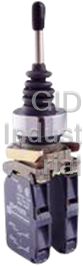


What they say about us
FANTASTIC RESOURCE
One of our top priorities is maintaining our business with precision, and we are constantly looking for affiliates that can help us achieve our goal. With the aid of GID Industrial, our obsolete product management has never been more efficient. They have been a great resource to our company, and have quickly become a go-to supplier on our list!
Bucher Emhart Glass
EXCELLENT SERVICE
With our strict fundamentals and high expectations, we were surprised when we came across GID Industrial and their competitive pricing. When we approached them with our issue, they were incredibly confident in being able to provide us with a seamless solution at the best price for us. GID Industrial quickly understood our needs and provided us with excellent service, as well as fully tested product to ensure what we received would be the right fit for our company.
Fuji
HARD TO FIND A BETTER PROVIDER
Our company provides services to aid in the manufacture of technological products, such as semiconductors and flat panel displays, and often searching for distributors of obsolete product we require can waste time and money. Finding GID Industrial proved to be a great asset to our company, with cost effective solutions and superior knowledge on all of their materials, it’d be hard to find a better provider of obsolete or hard to find products.
Applied Materials
CONSISTENTLY DELIVERS QUALITY SOLUTIONS
Over the years, the equipment used in our company becomes discontinued, but they’re still of great use to us and our customers. Once these products are no longer available through the manufacturer, finding a reliable, quick supplier is a necessity, and luckily for us, GID Industrial has provided the most trustworthy, quality solutions to our obsolete component needs.
Nidec Vamco
TERRIFIC RESOURCE
This company has been a terrific help to us (I work for Trican Well Service) in sourcing the Micron Ram Memory we needed for our Siemens computers. Great service! And great pricing! I know when the product is shipping and when it will arrive, all the way through the ordering process.
Trican Well Service
GO TO SOURCE
When I can't find an obsolete part, I first call GID and they'll come up with my parts every time. Great customer service and follow up as well. Scott emails me from time to time to touch base and see if we're having trouble finding something.....which is often with our 25 yr old equipment.
ConAgra Foods