

 Manufacturers
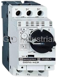
SCHNEIDER ELECTRIC GV2P20
Description
Schneider Electric GV2P20 Manual Motor Starter and Protector (TeSys GV2) Rotary Handle, Trip: 13A to 18A
Part Number
GV2P20
Price
Request Quote
Manufacturer
SCHNEIDER ELECTRIC
Lead Time
Request Quote
Category
Motor Starters
Specifications
Breaking Capacity Current AC
50kA
Connection
Screw Clamp
Construction Standard
Iec
Current Max
18A
Current Min
13A
Depth (in.)
3.83
Description/Special Features
Class 10 Ambient-Compensated Thermal Overload Relay, Instantaneous Trip Mechanism
External Depth
97mm
External Length/Height
89mm
External Width
44.5mm
Height (in.)
3.50
HP @ 1 Phase - 115v
1
HP @ 1 Phase - 230v
3
HP @ 3 Phase - 200v
5
HP @ 3 Phase - 230v
5
HP @ 3 Phase - 460-575v
10/15
Max. Voltage
600
Motor Power
1HP@115VAC - 3HP@230VAC
Mounting Type
DIN Rail
No. of Poles
3
Operator
Rotary Handle
Output Power
7.5kW
Overloads
Bimetallic Ambient Temperature Compensated Class 10, Thermal Setting 13 to 18 A
Reset Type
Ambient Compensated Bimetallic (Class 10)
Series
GV2
Starter Type
Manual
Tripping Current Range
223A
Voltage Rating VAC
575V
Weight
0.35kg
0.80
Width (in.)
1.75
Datasheet

Extracted Text
Accurate and reliable control of motors TeSys range provide you more simplicity, compactness, openness and flexibility ... so many evolutions and new items to aid your productivity. For a new start! TeSys A range of simple, compact and advanced components for power control and protection. New horizons are opening up to you. Increase your productivity - adopt our solutions which help to simplify setting-up. Motor starters Ready-to-use component combinations, b designed to work together in perfect harmony. b Safe operation and level of coordination guaranteed by a major manufacturer. Power circuit control A wide range of components. b b Solutions for a variety of power control applications: lighting, capacitor switching, heating, changeover contactor pairs, resistive loads, upstream protection. The essential guide A simplified selection guide enabling you to quickly select motor starters. 5/0 Motor control Contents Motor control components TeSys contactors ................................................................. 5/2 to 5/9 b Contactors, models K, D, F TeSys protection components ...................................... 5/10 to 5/21 b Manual motor starters b Switch-disconnector-fuses b Thermal overload relays b Electronic thermal overload relays b Multifunction protection relays b Switch disconnectors Mini Vario and Vario TeSys starters ................................................................. 5/22 to 5/25 b Self-protected starter, U-Line b Solid state overload relay system, U-Line 5 IEC type industrial control relays.................................. 5/26 to 5/29 b TeSys type CA2K, CA3K and CA4K b TeSys type CAD NEMA type ....................................................................... 5/30 to 5/49 b Contactors and starters b Combination starters ® b Solid state overload relays Motor Logic b Definite purpose contactors TeSys U - LU9 b Lighting contactors Control increases in power b Manual starters and switches b Accessories b Industrial control relays b Circuit breaker operating mechanisms b Disconnect switches Simply Smart benefits st intelligent starter Introducing the 1 capable of integrating motor control, control and changeover functions in a unit 45 mm wide! Simple in its modular format, it is also open to standard buses and can monitor your applications via the web. Applications b b b Industry: ideal solution when the motor b b starter needs to be decentralized in the machine or the process 5/1 TeSys Contactors 0.5–10 Hp K-line Connections ■ screw clamp terminals Rated operational current Ie max AC-3 (Ue - 440V) 6 A 9 A 12 A Ie AC-1 (θ - 40° C) - 20 A - Rated operational power 220/240 V 2 Hp 3 Hp 4 Hp in category AC3 380/400 V–415/440 V 3 Hp 5 Hp 7.5 Hp 660/690 V–500 V 4 Hp 5 Hp 5 Hp Contactor type (1)(2) AC LC1K06• LC1K09 LC1K12 DC LP1K06 or LP4K06 LP1K09 or LP4K09 LP1K12 or LP4K12 Reversing contactor type (2) AC LC2K06 LC2K09 LC2K12 with mechanical interlock DC LP2K06 or LP5K06 LP2K09 or LP5K09 LP2K12 or LP5K12 ■ spring terminals Add the figure 3 before the voltage code. Example LC1K0610 becomes LC1K06103 ■ slip-on connectors, 1 x 6.35 or 2 x 2.8 Add the figure 7 before the voltage code. Example LC1K0610 becomes LC1K06107 5 ■ solder pins for printed circuit boards Add the figure 5 before the voltage code. Example LC1K0610 becomes LC1K06105 (1) Basic catalog number, to be completed by adding 01 for N.C. auxiliary contact, or 10 for N.O. auxiliary contact. (2) Basic catalog number to be completed by adding the coil voltage. Example (including auxiliary contact) LC1RO601G7. Standard control circuit voltages AC supply Contactors LC1K (0.8–1.15 Uc) (0.85–1.1UC) Volts 12 20 24 36 42 48 110 115 120 127 200/208 220/230 230 230/240 50/60 Hz J7 Z7 B7 C7 D7 E7 F7 FE7 G7 FC7 L7 M7 P7 U7 Volts 256 277 380/400 400 400/415 440 480 500 575 600 660/690 50/60 Hz W7 UE7 Q7 V7 N7 R7 T7 S7 SC7 X7 Y7 Example of complete catalog number LC1K0910P7. DC supply Contactors LP1K (0.8–1.15 Uc) Volts 12 20 24 36 48 60 72 100 110 125 155 174 200 220 230 240 250 Code JD ZD BD CD ED ND SD KD FD GD PD QD LD MD MPD MUD UD Coil with integral suppression device available, add 3 to the code required. Example JD3 Low consumption Contactors LP4K (0.7–1.30 Uc), coil suppression as standard Volts 12 20 24 48 72 110 120 Code JW3 ZW3 BW3 EW3 SW3 FW3 GW3 Example of complete catalog number LC1K0910BD. For other versions, please consult with your localSchneider Electric / 5/2 Square D sales office: visit www.us.telemanique.com. TeSys K-line Auxiliary contact blocks ■ ■ ■ instantaneous, screw clamp connections ■ ■ ■ ■ ■ for LC1, LP1K, LP4 ■ ■ ■ for LC1, LP1K ■ ■ ■ ■ Composition 2 N.O. - 2 N.C. 1 N.O. 1 N.C. 4 N.O. 3 N.O. 1 N.C. 2 N.C. 2 N.C. 1 N.O. 3 N.C. - 4 N.C. Catalog number LA1KN20 LA1KN02 LA1KN11 LA1KN40 LA1KN31 LA1KN22 LA1KN13 LA1KN04 ■ ■ ■ electronic time delay ■ ■ Relay outputs, with common point changeover contact, AC or DC 24–48, 2 A maximum Control voltage 0.85–1.1Uc Maximum switching capacity 250 VA or 150 W Operating temperature -10 to + 60°C Reset time: 1.5 s for 0.5 s after the time delay period Type On-delay Timing range 1–30 s Composition 1 Voltage AC or DC 24–48 V AC 110–240 5 Reference LA2KT2E LA2KT2U Suppressor modules For LC1, LP1K Type Varistor (AC and DC) Diode (DC) + zener RC (AC) Voltage 12–24 V 32–48 V 50–129 V 130–250 V 12–24 V 32–48 V 110–250 V Catalog number LA4KE1B LA4KE1E LA4KE1FC LA4KE1UG LA4KC1B LA4KC1E LA4KA1U For other versions, please consult with your local Schneider Electric/ Square D sales office: visit www.us.telemanique.com. 5/3 TeSys Contactors 0.5–125 Hp D-line Connections ■ ■ ■ screw clamp terminals or connectors ■ ■ Rated operational voltage 690 V Rated operational current Ie max AC-3 (Ue - 440V) 9 A 12 A 18 A 25 A 32 A Ie AC-1 (θ - 60° C) 25 A 32 A 40 A 50 A Rated operational power 220/240 V 3 Hp 4 Hp 5 Hp 7.5 Hp 10 Hp in category AC3 380/400 V 5 Hp 7.5 Hp 10 Hp 15 Hp 20 Hp 415/440 V 5 Hp 7.5 Hp 12 Hp 15 Hp 20 Hp 500 V 7.5 Hp 10 Hp 13 Hp 20 Hp 25 Hp 660/690 V 7.5 Hp 10 Hp 13 Hp 20 Hp 25 Hp 1000 V - - - - - Contactor type (1) LC1D09 LC1D12 LC1D18 LC1D25 LC1D32 Reversing contactor type * with mechanical interlock LC2D09 LC2D12 LC2D18 LC2D25 LC2D32 ■ ■ ■ spring terminals (1) ■ ■ Add the figure 3 before the voltage code. Example LC1D09P7 becomes LC1093P7 5 ■ ■ ■ ring tongue terminals (2) ■ ■ Add the figure 6 before the voltage code. Example LC1D09P7 becomes LC1096P7 ■ ■ ■ slip-on connectors (3) 2 x 6.35 (power) and 1 x 6.35 (control) up to D12 only ■ ■ Add the figure 9 before the voltage code. Example LC1D09P7 becomes LC1099P7 (1) Basic catalog number to be completed by adding the coil voltage. Example: LC1D09P7. (1) LC1D093P7 (3) LC1D099P7 (2) LC1D096P7 Standard control circuit voltages AC supply Volts 24 42 48 110 115 220 230 240 380 400 415 440 500 Contactors LC1D09–D50 (coils D115 and D150 with integral suppression device fitted as standard) 50/60 Hz B7 D7 E7 F7 FE7 M7 P7 U7 Q7 V7 N7 R7 - Contactors LC1D40–D115 50 Hz B5 D5 E5 F5 FE5 M5 P5 U5 Q5 V5 N5 R5 S5 60 Hz B6 - E6 F6- M6 - U6Q6 - - R6 - DCsupply Volts 12 24 36 48 60 72 110 125 220 250 440 Contactors LC1D09–D38 (coils with integral suppression device fitted as standard) U 0.7–1.25 Uc JD BD CD ED ND SD FD GD MD UD RD Contactors LC1D40–D95 U 0.85–1.1 Uc JD BD CD ED ND SD FD GD MD UD RD U 0.75–1.2 Uc JW BW CW E W - S W FW - M W - - Contactors LC1D115 and D150 (coils with integral suppression device fitted as standard) U 0.75–1.2 Uc - BD - ED ND SD FD GD MD UD RD Low consumption Contactors LC1D09–D38 (coils with integral suppression device fitted as standard) Volts DC 5 12 20 24 48 110 120 250 U 0.7–1.25 Uc AL JL Z L BL EL F L ML UL Example of complete catalog number LC1D09P7. For enclosed version of d-Line starters up to 80A, reference catalog 8502CT9901. For other versions, please consult with your localSchneider Electric / 5/4 Square D sales office: visit www.us.telemanique.com. TeSys D-line 1000 V on AC supply, 690 V on DC supply 38 A 40 A 50 A 65 A 80 A 95 A 115 A 150 A 60 A 80 A 125 A 200 A 12 Hp 15 Hp 20 Hp 25 Hp 30 Hp 30 Hp 40 Hp 50 Hp 25 Hp 25 Hp 30 Hp 40 Hp 50 Hp 60 Hp 75 Hp 100Hp 25 Hp 30 Hp 30/40 Hp 50 Hp 60 Hp 60 Hp 75 Hp 100 Hp 25 Hp 30 Hp 40 Hp 50 Hp 75 Hp 75 Hp 100 Hp 125Hp 25 Hp 40 Hp 44 Hp 50 Hp 60 Hp 60 Hp 100 Hp 125Hp - 30 Hp 40 Hp 50 Hp 60 Hp 60 Hp 100 Hp 125 Hp LC1D38 LC1D40 LC1D50 LC1D65 LC1D80 LC1D95 LC1D115 LC1D150 LC2D38 LC2D40 LC2D50 LC2D65 LC2D80 LC2D95 LC2D115 LC2D150 5 Mounting accessories for 3-pole reversing contactors 2 identical contactors with screw clamp terminals or connectors, horizontally mounted Mechanical interlock Set of connections Mechanical interlock ■ ■ ■ with an electrical interlocking kit for the contactors ■ ■ LC1D09–D38 LAD9R1V included ■ ■ ■ with integral electrical interlocking ■ ■ LC1D40–D65 LA9D6569 LA9D4002 LC1D80 and D95 (AC) LA9D8069 LA9D4002 LC1D80 and D95 (DC) LA9D8069 LA9D8002 LC1D115 and D150 LA9D11569 LA9D11502 ■ ■ ■ without electrical interlocking ■ ■ LC1D09–D38 LA99R1 included LC1D40–D65 LA9D6569 LA9D50978 LC1D80 and D95 (AC) LA9D8069 LA9D50978 LC1D80 and D95 (DC) LA9D8069 LA9D80978 Mechanical latch blocks Clip-on front mounting, manual or electrical unlatching control For use on contactor Catalog number Standard control circuit voltages LC1D40–D65 3P AC or DC, LC1D65 4P AC, LC1D65 4P DC LA6DK10 B E F M Q LC1D80–D150 3P AC, LC1D80 and D115 3P AC, LC1D115 4P DC LA6DK20 B E F M Q LC1D09–D38 AC or DC, LC1DT20–DT40 AC or DC LA66K10 B E F M Q For other versions, please consult with your local Schneider Electric/ Square D sales office: visit www.us.telemanique.com. 5/5 TeSys Contactors 0.5–125 Hp D-line Auxiliary contact blocks ■ ■ ■ instantaneous, for connection by screw clamp terminals ■ ■ ■ time delay ■ ■ ■ ■ ■ ■ ■ front mounting ■ ■ ■ side mounting ■ ■ ■ front mounting ■ ■ ■ ■ ■ ■ Composition Catalog number Composition Catalog number Composition Catalog number Composition Catalog number Type Range Catalog number N.O. N.C. N.O. N.C. N.O. N.C. N.O. N.C. 1- LADN10 11 LADN11 22 LADN22 11 LAD8N11 On-delay 0.1–3 s LADT0 -1 LADN01 2- LADN20 13 LADN13 2- LAD8N20 0.1–30 s LADT2 -2 LADN02 4- LADN40 -2 LAD8N02 10–180 s LADT4 -4 LADN04 Off-delay 0.1–3 s LADR0 31 LADN31 0.1–30 s LADR2 10–180 s LADR4 5 Maximum number of auxiliary contacts that can be fitted Contactors Instantaneous auxiliary contact blocks Time delay Type Number of poles and size Side mounting Front mounting Front mounting 1 contact 2 contacts 4 contacts AC 3P LC1D09–D38 1 on LH side and - 1 or 1 or 1 LC1D40–D95 (50/60 Hz) 1 on each side or 2 and 1 or 1 or 1 LC1D40–D95 (50 or 60 Hz) 1 on each side and 2 and 1 or 1 or 1 LC1D115 and D150 1 on LH side - and 1 or 1 or 1 4P LC1DT20–DT40 1 on LH side - 1 or 1 or 1 LC1D65 and D80 1 on each side or 1 or 1 or 1 or 1 LC1D115 1 on each side and 1 or 1 or 1 or 1 DC 3P LC1D09–D38 - - 1 or 1 or 1 LC1D40–D95 - 1 or 1 or 1 or 1 LC1D115 and D150 1 on LH side and - 1 or 1 or 1 4P LC1DT20–DT40 - - 1 or 1 or 1 LP1D65 and D80 - 2 and 1 or 1 or 1 LC1D115 1 on each side - and 1 or 1 or 1 Low Consumption 3P LC1D09–D38 --1 -- 4P LC1DT20–DT40 --1 For other versions, please consult with your localSchneider Electric / 5/6 Square D sales office: visit www.us.telemanique.com. TeSys D-line Suppressor modules Varistors (peak limiting) Protection provided by limiting the transient voltage to 2 Uc max. Maximum reduction of transient voltage peaks. Slight increase in drop-out time (1.1 to 1.5 times the normal time) Mounting For use with contactor Type Catalog number Rating VAC VDC Clip-on D09–D38 (3P) 12–24 V - LAD4VE DT20–DT40 (4P) 50–127 V - LAD4VG 110–240 V - LAD4VU Screw clamp D40–D115 (3P) 24–48 V - LA4DE2E and 50–127 V - LA4DE2G D65–D115 (4P) 110–250 V - LA4DE2U D40–D115 (3P) - 24–48 V LA4DE3E and - 50–127 V LA4DE3G 5 D65–D115 (4P) - 110–250 V LA4DE3U Diodes No overvoltage or oscillating frequency. Increase in drop-out time (6 to 10 times the normal time). Polarised component. Screw clamp D40–D95 (3P) - 24–250 V LA4DC3U D65 and D80 (4P) Bidirectional peak limiting diode Protection provided by limiting the transient voltage to 2 Uc max. Maximum reduction of transient voltage peaks. Clip-on D09–D38 (3P) 24 V - LAD4TB DT20–DT40 (4P) 72 V - LAD4TS Screw clamp D40–D95 (3P) 24 V - LA4DB2B D65 and D80 (4P) 72 V - LA4DB2S D40–D95 (3P) - 24 V LA4DB3B D65 and D80 (4P) - 72 V LA4DB3S RC circuits (Resistor-Capacitor) Effective protection for circuits highly sensitive to "high frequency" interference. For use only in cases where the voltage is virtually sinusoidal, i.e. less than - 5% total harmonic distortion. Voltage limited to 3 Uc max and oscillating frequency limited to 400 Hz max. Slight increase in drop-out time (1.2 to 2 times the normal time) Clip-on D09–D38 (3P) 12–24 V - LAD4RCE DT20–DT40 (4P) 110–240 V - LAD4RCU Screw fixing D40–D150 (3P) 24–48 V - LA4DA2E and 50–127 V - LA4DA2G D65–D115 (4P) 110–240 V - LA4DA2U 380–415 V - LA4DA2N For other versions, please consult with your local Schneider Electric/ Square D sales office: visit www.us.telemanique.com. 5/7 TeSys Contactors 30–900 Hp F-line Rated operational current Ie max AC-3 (Ue - 440V) 185 A 225 A 265 A 330 A Ie AC-1 (θ - 40° C) 275 A 315 V 350 A 400 A Rated operational voltage 1 000 V 1 000 V 1 000 V 1 000 V Number of poles 3 or 4 3 or 4 3 or 4 3 or 4 Rated operational power 220/240 V 75 Hp 75 Hp 100 Hp 125 Hp in category AC3 380/400 V 125 Hp 150 Hp 200 Hp 250 Hp 415 V 125 Hp 150 Hp 175 Hp 220 Hp 440 V 125 Hp 150 Hp 175 Hp 300 Hp 500 V 150 Hp 175 Hp 250 Hp 300 Hp 660/690 V 150 Hp 175 Hp 250 Hp 350 Hp 1000 V 125 Hp 125 Hp 200 Hp 250 Hp Contactor type (1) LC1F185 LC1F225 LC1F265 LC1F330 Reversing contactor type (1) LC2F185 LC2F225 LC2F265 5 (1) Basic catalog number to be completed by adding the coil voltage code. Example: LC1F18567. Standard control circuit voltages AC supply Volts 24 48 110 115 120 208 220 230 240 380 400 415 440 Contactors LC1F115–F225(0.85–1.1UC) 50 Hz (coil LX1) B5 E5 F5 FE5 - - M5 P5 U5 Q5 V5 N5 - 60 Hz (coil LX1) - E6F6- G6 L6M6 - U6 Q6 - - R6U7 40–400 Hz (coil LX9) - E7 F7 FE7 G7 L7 M7 P7 U7 Q7 V7 N7 R7 Contactors LC1F265–F330U7 40–400 Hz (coil LX1) B7 E7 F7 FE7 G7 L7 M7 P7 U7 Q7 V7 N7 R7 Contactors LC1F400–F630U7 40–400 Hz (coil LX1) - E7F7FE7 G7 (1) L7 M7 P7 U7 Q7 V7 N7 R7 Contactor LC1F780U7 40–400 Hz (coil LX1) - - F7 FE7 F7 L7 M7 P7 U7 Q7 V7 N7 R7 Contactor LC1F800U7 40–400 Hz (coil LX1) - - FE7 FE7 FE7 - P7 P7 P7 V7 V7 V7 V7Y7 DC supply Volts 24 48 110 125 220 230 250 400 440 Contactors LC1F115–F330(0.85–1.1UC) (coil LX4F) BD ED FD GD MD MD UD - RD Contactors LC1F400–F630(0.85–1.1UC) (coil LX4F) -ED FD GD MD -UD - RD Contactor LC1F780(0.85–1.1UC) (coil LX4F) -- FD GD MD -UD - RD Contactor LC1F800(0.85–1.1UC) (coil LX4F) - - FW FW MW MW - QW - Example: For a 630 A contactor with a 110 VAC coil, order LC1F630F7. (1) F7 for LC1F630. For other versions, please consult with your localSchneider Electric / 5/8 Square D sales office: visit www.us.telemanique.com. TeSys F-line 400 A 500 A 630 A 780 A 800 A 500 A 700 A 1 000 A 1 600 A 1 000 A 1 000 V 1 000 V 1 000 V 1 000 V 1 000 V 2, 3 or 4 2, 3 or 4 2, 3 or 4 3 or 4 3 150 Hp 200 Hp 300 Hp 350 Hp 400 Hp 300 Hp 400 Hp 450 Hp 600 Hp 600 Hp 350 Hp 450 Hp 500 Hp 500 Hp 600 Hp 400 Hp 400 Hp 600 Hp 500 Hp 600 Hp 300 Hp 475 Hp 600 Hp 600 Hp 600 Hp 450 Hp 450 Hp 600 Hp 600 Hp 600 Hp 250 Hp 450 Hp 600 Hp 600 Hp 600 Hp LC1F400 LC1F500 LC1F630 LC1F780 LC1F800 For customer assembly 5 Auxiliary contact blocks ■ ■ ■ instantaneous dust & damp protected contacts ■ ■ ■ time delay 1N.O. + 1 N.C. ■ ■ ■ ■ Composition Catalog number Composition Catalog number Composition Catalog number Composition Catalog number Type Range Catalog number N.O. N.C. N.O. N.C. N.O. N.C. N.O. N.C. 1- LADN10 11 LADN11 22 LADN22 2 - - - LA1DX20 On-delay 0.1–3 s LADT0 -1 LADN01 2- LADN20 13 LADN13 22- - LA1DY20 0.1–30 s LADT2 -2 LADN02 4- LADN40 2- 2 - LA1DZ40 10–180 s LADT4 -4 LADN04 2- 1 1 LA1DZ31 1–30 s LADS2 31 LADN31 Off-delay 0.1–3 s LADR0 22 LADC22 0.1–30 s LADR2 10–180 s LADR4 Mounting accessories for 3-pole reversing contactors for motor control 2 identical contactors, horizontally mounted Mechanical interlock with an electrical interlocking kit for the contactors Contactor type Set of connections Mechanical interlock LC1F115 LA9FF976 LA9FF970 LC1F150 LA9F15076 LA9FF970 LC1F185 LA9FG976 LA9FG970 LC1F225 LA9F22576 LA9FG970 LC1F265 LA9FH976 LA9FJ970 LC1F330 LA9FJ976 LA9FJ970 LC1F400 LA9FJ976 LA9FJ970 LC1F500 LA9FK976 LA9FJ970 LC1F630 or LC1F800 LA9FL976 LA9FL970 For other versions, please consult with your local Schneider Electric/ Square D sales office: visit www.us.telemanique.com. 5/9 TeSys Manual motor starters 0.1–30 Hp Type GVZME and GV2P Manual motor starters GV2ME and GV2P for connection by screw clamp terminals GV2ME with pushbutton control, GV2P control by rotary knob Horsepower ratings of 3-phase motors 50/60 Hz Setting range Magnetic Catalog Number 200 V 230 V 460 V 575 V of thermal tripping trips current Push button Rotary Handle AA - - - - 0.1–0.16 1.5 GV2ME01 GV2P01 - - - - 0.16–0.25 2.4 GV2ME02 GV2P02 - - - - 0.25–0.40 5 GV2ME03 GV2P03 - - - - 0.40–0.63 8 GV2ME04 GV2P04 - - 0.5 0.5 0.63–1 13 GV2ME05 GV2P05 - - 0.75 1 1–1.6 22.5 GV2ME06 GV2P06 0.5 0.5 1 1.5 1.6–2.5 33.5 GV2ME07 GV2P07 0.75 1 2 3 2.5–4 51 GV2ME08 GV2P08 1.5 1.5 3 5 4–6.3 78 GV2ME10 GV2P10 5 2 3 5 7.5 6–10 138 GV2ME14 GV2P14 3 3 10 10 9–14 170 GV2ME16 GV2P16 5 5 10 15 13–18 223 GV2ME20 GV2P20 5 7.5 15 20 17–23 327 GV2ME21 GV2P21 5 7.5 15 20 20–25 327 GV2ME22 GV2P22 10 10 20 30 24–32 416 GV2ME32 GV2P32 Thermal-magnetic circuit-breakers GV2ME for connection by spring terminals Add the number 3 to the end of the catalog number. Example GV2ME223 (available up to GV2ME22) Thermal-magnetic circuit-breakers GV2ME for connection by spring terminals Add the figure 3 to the end of the catalog number. Example GV2ME223 (available up to GV2ME22) Fuse holder—30 A rated, type CC or KTK-R fuses Catalog Number With screw terminals LS1D30 With spring terminals LS1D303 Auxiliary pole (screw terminals; LA8D324 mount on left or right side) For other versions, please consult with your localSchneider Electric / 5/10 Square D sales office: visit www.us.telemanique.com. TeSys Type GVZME and GV2P Accessories Combination block For mounting on LC1K or LP1K LC1D09–D38 LAD31 and LC1D09–D38 GV2AF01 GV2AF3 GV2AF4 Sets of 3-pole busbars 63 A Pitch 45 mm 54 mm 72 mm Number of tap-offs 2 GV2G245 GV2G254 GV2G272 3 GV2G345 GV2G354 4 GV2G445 GV2G454 GV2G472 5 GV2G554 Protective end cover For unused busbar outlets GV1G10 Terminal blocks For supply to one or more GV2G busbar sets connection from the top can be fitted with current limiter GV1L3 (GV2ME and GV2P) GV1G09 GV1G05 5 Padlockable external operator for GV2P (150 to 290 mm) Padlocking In “On” and “Off ” position In “Off ” position Handle black red Legend plate blue yellow IP 54 GV2AP01 GV2AP02 Padlocking device For all GV2 devices For use with up to 6 padlocks (padlocks not supplied) Ø 6 mm shank max GV2V03 Add-on blocks Contact blocks Contact types N.O. or N.C. N.O. + N.C. N.O. + N.O. (fault) + N.C. N.C. + N.O. C.O. common Instantaneous auxiliary contacts point Mounting front GVAE1 GVAE11 GVAE20 LH side GV AN11 GVAN20 Fault signalling contact + instantaneous auxiliary contact LH side GVAD1010 GVAD1001 GVAD0110 GVAD0101 Short-circuit signalling contact LH side GVAM11 Electric trips Undervoltage or shunt trips (1) Side mounting (1 block on RH side of circuit-breaker) 50 Hz 60 Hz Voltage (AC) 24 V GVA025 GVA026 48 V GVA055 GVA056 100 V GVA 107 100–110 V GVA107 110–115 V GVA115 GVA116 120–127 V GVA 125 127 V GVA115 200 V GVA207 200–220 V GVA 207 220–240 V GVA225 GVA226 380–400 V GVA385 GVA386 415–440 V GVA 415 415 V GVA416 (1) Undervoltage trips: replace the with U, shunt trips: replace the with S For other versions, please consult with your local Schneider Electric/ Square D sales office: visit www.us.telemanique.com. 5/11 TeSys Manual motor starters 0.5–60 Hp Type GV3ME Manual motor starters GV3ME for connection by screw clamp terminals Pushbutton control Horsepower ratings of 3-phase motors 50/60 Hz Setting range of thermal trips Catalog Number 200 V 230 V 460 V 575 V A - - 0.75 1 1–1.6 GV3ME06 0.5 0.5 1 1.5 1.6–2.5 GV3ME07 0.75 1 2 3 2.5–4 GV3ME08 1.5 1.5 3 - 4–6 GV3ME10 2 3 5 7.5 6–10 GV3ME14 3 5 10 10 10–16 GV3ME20 5 7.5 15 20 16–25 GV3ME25 10 10 30 30 25–40 GV3ME40 20 20 40 60 40–63 GV3ME63 20 25 50 60 56–80 GV3ME80 5 Add-on blocks Contact blocks Instantaneous auxiliary contacts (1 per breaker) Normal early break type contacts N.C. + N.O. N.O. + N.O. N.C. + N.O. + N.O. N.O. + N.O. + N.O. N.O. + N.O. (1) N.C. + N.O. (1) GV3A01 GV3A02 GV3A03 GV3A05 GV3A06 GV3A07 Fault signalling contact Normal early break type contacts N.C. N.O. GV3A08 GV3A09 Electric trips Voltage 50 Hz 110, 120, 127 V 220, 240 V 380, 415 V 60 Hz 120, 127 V 277 V 440, 480 V Undervoltage trip GV3B11 GV3B22 GV3B38 Shunt trip GV3D11 GV3D22 GV3D38 Padlocking device Start button (for bare device) GV1V02 (1) + 2 volt free terminals For other versions, please consult with your localSchneider Electric / 5/12 Square D sales office: visit www.us.telemanique.com. Manual motor starters TeSys 1–120 Hp Type GV7R Manual motor starters GV7R for connection by screw clamp terminals Control by rocker lever Horsepower ratings of 3-phase motors 50/60 Hz Setting range of thermal trips Catalog Number 230 V 460V 575 V A 5 10 15 12–20 GV7RE20 5 10 15 12–20 GV7RS20 7.5 15 20 15–25 GV7RE25 7.5 15 20 15–25 GV7RS25 10 30 30 25–40 GV7RE40 10 30 30 25–40 GV7RS40 15 30 40 30–50 GV7RE50 30 60 75 48–80 GV7RE80 30 60 75 48–80 GV7RS80 30 75 100 60–100 GV7RE100 30 75 100 60–100 GV7RS100 5 50 100 150 90–150 GV7RE150 50 100 150 90–150 GV7RS150 75 150 200 132–220 GV7RE220 75 150 200 132–220 GV7RS220 Add-on blocks Contact blocks Auxiliary contacts Contact type C.O. GV7AE11 Thermal or magnetic fault discrimination 24–48 VAC/DC or 24–72 VDC 110–240 VAC/DC GV7AD111 GV7AD112 Electric trips Voltage 50/60 Hz 48 V 110–130 V 200–240 V 380–440 V 50 Hz 525 V Undervoltage trip (1) GV7AU055 GV7AU107 GV7AU207 GV7AU387 GV7AU525 Shunt trip (1) GV7AS055 GV7AS107 GV7AS207 GV7AS387 GV7AS525 (1) For mounting of a GV7AD or a GV7AU or AS Accessories Terminal shields IP 405 Supplied with the sealing accessory GV7AC01 Phase barriers used when fitting of shields is impossible GV7AC04 Insulating screens Ensure insulation between the connections and the backplate GV7AC05 Kit for combination with contactor Allowing link between the circuit-breaker and the contactor LC1F115 to F185 LC1F225 and F26 LC1D115 and D150 GV7AC06 GV7AC07 GV7AC08 Rotary handles Handle black red Legend plate black yellow ■ ■ ■ direct IP 40 GV7AP03 GV7AP04 ■ ■ ■ ■ ■ extended IP 55 GV7AP01 GV7AP02 ■ ■ Conversion accessory for mounting on enclosure door IP 43 GV7AP05 Locking device For starter not fitted with a rotary handle GV7V01 For other versions, please consult with your local Schneider Electric/ Square D sales office: visit www.us.telemanique.com. 5/13 TeSys Switch-disconnector-fuses 0–1250 A GS1 GS1 fusible disconnect switch 30–800 A Catalog number GS1DDU3 GS1DU3 GS1EERU20 GS1EERU30 GS1EEU3 Switch Type Compact fused Compact fused Fused Fused Fused Fuses CC J CC CC CC Amps 30 30 30 30 30 Poles 3323 3 Operator Style Thru-the-door Thru-the-door Side handle Side handle Thru-the-door Max. HP 3 Phase: kW/hp at 240V 5.5/7.5 5.5/7.5 n/a 5.5/7.5 5.5/7.5 kW/hp at 480V 11/15 11/15 n/a 11/15 11/15 kW/hp at 600V 15/20 15/20 n/a 15/20 15/20 5 LK3 non-fused disconnect switch 30–1200 A Catalog number LK3GU3 LK3GU3 LK3JU3 LK3MU3 (1) LK3QU3 (1) Switch Type Compact Non-fused Non-fused Non-fused Non-fused Non-fused Amps 30 60 100 200 400 Poles 3333 3 Operator Style Thru-the-door Thru-the-door Thru-the-door Thru-the-door Thru-the-door Max. HP 3 Phase: kW/hp at 240V 5.5.7.5 11/15 22/30 45/60 90/125 kW/hp at 480V 11/15 22/30 45/60 90/125 185/250 kW/hp at 600V 15/20 37/50 55/75 110/150 250/350 (1) Terminal lugs must be ordered separately. Auxiliary early break and/or signalling contacts Switch rating 30–200 A 50–400 A 600–800A 50–400 V Contact type 1 N.O. 1 N.C. 1 C.O. 2 C.O. 1 C.O. 2 C.O. 1 N.C. + 1 N.O. 2 N.C. + 2 N/O Standard contacts GS1AM110 GS1AM101 GS1AM1 GS1AM2 GS1AMU3 GS1AMU4 GS1AN11 GS1AN22 For other versions, please consult with your localSchneider Electric / 5/14 Square D sales office: visit www.us.telemanique.com. TeSys GS1 GS1EU3 GS1GU3 GS1JU3 (1) GS1MU3 (1) GS1QU3 (1) GS1SU3 (1) GS1TU3 (1) Fused Fused Fused Fused Fused Fused Fused J J JJJJL 30 60 100 200 400 600 800 3 3 33333 Thru-the-door Thru-the-door Thru-the-door Thru-the-door Thru-the-door Thru-the-door Thru-the-door 5.5/7.5 11/15 22/30 45/60 90/125 185/250 185/250 11/15 22/30 45/60 90/125 185/250 370/500 370/500 15/20 37/50 55/75 110/150 250/350 370/500 370/500 5 LK3SU3 (1) LK3TU3 (1) LK3UU3 (1) LK3WU3 Non-fused Non-fused Non-fused Non-fused 600 800 1000 1200 33 3 3 Thru-the-door Thru-the-door Thru-the-door Thru-the-door 150/200 185/250 185/250 185/250 300/400 370/500 370/500 370/500 250/350 370/500 370/500 370/500 (1) Terminal lugs must be ordered separately. For other versions, please consult with your local Schneider Electric/ Square D sales office: visit www.us.telemanique.com. 5/15 TeSys Thermal overload relays 0.11–11.5 A K-line Thermal overload relays, model k adjustable from 0.11 to 12 A Connection by screw clamp terminals, direct mounting on contactors LC1K, manual or automatic reset Relay setting range Fuses to be used with selected relay (international applications only) (5) Catalog number Class 10 A aM gG BS88 0.11–0.16 A 0.25 A 0.5 A - LR2K0301 0.16–0.23 A 0.25 A 0.5 A - LR2K0302 0.23–0.36 A 0.5 A 1 A - LR2K0303 0.36–0.54 A 1 A 1.6 A - LR2K0304 0.54–0.8 A 1 A 2 A - LR2K0305 0.8–1.2 A 2 A 4 A 6 A LR2K0306 1.2–1.8 A 2 A 6 A 6 A LR2K0307 1.8–2.6 A 2 A 6 A 10 A LR2K0308 2.6–3.7 A 4 A 10 A 16 A LR2K0310 3.7–5.5 A 6 A 16 A 16 A LR2K0312 5 5.5–8 A 8 A 20 A 20 A LR2K0314 8–11.5 A 10 A 25 A 20 A LR2K0316 Thermal overload relays for use on class 10 A unbalanced loads: for above catalog numbers LR2K0305 to LR2K0316 only, replace the prefix LR2 with LR7. Example LR7K0310. Accessories Prewiring kit Allowing direct connection of the N.C. contact For use on of relay LRD01–35 or LR3D01–D35 to the contactor LC1D09–D18 LAD7C1 LC1D25–D38 LAD7C2 Terminal blocks (1) For clip-on mounting on 35 mm mounting rail (AM1-DP200) LRD01–35 and LR3D01–D35 LAD7B10 or screw fixing LRD3, LR3D3, LRD35 LA7D3064 (2) For independent mounting of the relay LR2K LA7K0064 Terminal block adapter For mounting a relay beneath an LC1D115 or D150 contactor LRD3, LR3D3, LRD35 LA7D3058 Stop or electrical reset Remote(3) LRD01–35 and LR3D01–D35 LAD703 (4) Tripping or electrical reset device Remote(3) All relays except LRD01–35 and LR3D01–D35 LA7D03 (4) (1) Terminal blocks are supplied with terminals protected against direct finger contact and scre ws in the open “ready-to-tighten” position. (2) To order a terminal block for connection by lug-clamps, the catalog number becomes LA7D30646. (3) The time for which the coil of remote tripping or electrical resetting device LA76D03 or LAD703 can remain energized depends on its rest time: 1 s pulse duration with 9 s rest time; maximum pulse duration of 20 s with a rest time of 300 s. Minimum pulse time 200 ms. (4) Catalog number to be completed by adding the code indicating the control circuit voltage. (5) Short circuit protection for U.S. applications: circuit breakers selected in accordance with NEC and local codes; fuses selected with maximum of 400% full load current. Standard control circuit voltages AC supply Volts 12 24 48 96 110 220/230 380/400 415/440 50/60 Hz. Consumption, inrush and sealed < 100 VA -B E -F M Q N DC supply Consumption, inrush and sealed < 100 W JB E DD F M - - For other versions, please consult with your localSchneider Electric / 5/16 Square D sales office: visit www.us.telemanique.com. Thermal overload relays TeSys 0.1–140 A D-line Thermal overload relays, model d adjustable from 0.1 to 140 A Compensated relays with manual or automatic reset, with relay trip indicator, for AC or DC Relay setting range Fuses to be used with selected relay (international applications only) (5) With contactor Catalog number aM gG BS88 Class 10 A 0.10–0.16 A 0.25 A 2 A - LC1D09–D38 LRD01 0.16–0.25 A 0.5 A 2 A - LC1D09–D38 LRD02 0.25–0.40A 1 A 2 A - LC1D09–D38 LRD03 0.40–0.63 A 1 A 1.6 A - LC1D09–D38 LRD04 0.63–1 A 2 A 4 A - LC1D09–D38 LRD05 1–1.7 A 2 A 4 A 6 A LC1D09–D38 LRD06 1.6–2.5 A 4 A 6 A 10 A LC1D09–D38 LRD07 2.5–4 A 6 A 10 A 16 A LC1D09–D38 LRD08 4–6 A 8 A 16 A 16 A LC1D09–D38 LRD10 5.5–8 A 12 A 20 A 20 A LC1D09–D38 LRD12 5 7–10 A 12 A 20 A 20 A LC1D09–D38 LRD14 9–13 A 16 A 25 A 25 A LC1D12–D38 LRD16 12–18 A 20 A 35 A 32 A LC1D18–D38 LRD21 16–24 A 25 A 50 A 50 A LC1D25–D38 LRD22 23–32 A 40 A 63 A 63 A LC1D25–D38 LRD32 30–38 A 50 A 80 A 80 A LC1D32 and D38 LRD35 17–25 A 25 A 50 A 50 A LC1D40–D95 LRD3322 23–32 A 40 A 63 A 63 A LC1D40–D95 LRD3353 30–40 A 40 A 100 A 80 A LC1D40–D95 LRD3355 37–50 A 63 A 100 A 100 A LC1D40–D95 LRD3357 48–65 A 63 A 100 A 100 A LC1D50–D95 LRD3359 55–70 A 80 A 125 A 125 A LC1D50–D95 LRD3361 63–80 A 80 A 125 A 125 A LC1D65 and D95 LRD3363 80–104 A 100 A 160 A 160 A LC1D80 and D95 LRD3365 80–104 A 125 A 200 A 160 A LC1D115 and D150 LRD4365 95–120 A 125 A 200 A 200 A LC1D115 and D150 LRD4367 110–140 A 160 A 250 A 200 A LC1D150 LRD4369 80–104 A 100 A 160 A 160 A (1) LRD33656 95–120 A 125 A 200 A 200 A (1) LRD33676 110–140 A 160 A 250 A 200 A (1) LRD33696 Class 20 A 6 A 10 A 16 A LC1D09–D32 LRD1508 4–6 A 8 A 16 A 16 A LC1D09–D32 LRD1510 5.5–8 A 12 A 20 A 20 A LC1D09–D32 LRD1512 7–10 A 16 A 20 A 25 A LC1D09–D32 LRD1514 9–13 A 16 A 25 A 25 A LC1D12–D32 LRD1516 12–18 A 25 A 35 A 40 A LC1D18–D32 LRD1521 17–25 A 32 A 50 A 50 A LC1D25 and D32 LRD1522 23–28 A 40 A 63 A 63 A LC1D25 and D32 LRD1530 25–32 A 40 A 63 A 63 A LC1D25 and D32 LRD1532 17–25 A 32 A 50 A 50 A LC1D40–D95 LR2D3522 23–32 A 40 A 63 A 63 A LC1D40–D95 LR2D3553 30–40 A 50 A 100 A 80 A LC1D40–D95 LR2D3555 37–50 A 63 A 100 A 100 A LC1D50–D95 LR2D3557 48–65 A 80 A 125 A 100 A LC1D50–D95 LR2D3559 55–70 A 100 A 125 A 125 A LC1D65–D95 LR2D3561 63–80 A 100 A 160 A 125 A LC1D80 and D95 LR2D3563 (1) Separate mounting. Screw clamp terminal connections or connectors. For spring terminal connections on LRD01 to LRD22, add 3 to the end of the catalog number. Example: LRD01 becomes LRD013. For lug-clamp connections, add 6 to the end of the catalog number . Example: LRD01 becomes LRD016. For thermal overload relays for use with class 10 A unbalanced loads, with connection by screw clamp terminals, change the prefix in the catalog n umbers above from LRD (except LRD4) to LR3D. Example LRD01 becomes LR3D01. (5) Short circuit protection for U.S. applications: circuit breakers selected in accordance with NEC and local codes; fuses selected with maximum of 400% full load current. For other versions, please consult with your local Schneider Electric/ Square D sales office: visit www.us.telemanique.com. 5/17 TeSys Electronic thermal overload relays 60–630 A F-line For use with contactor LC1D LC1F Motor current 60–150 A 30–630 A Catalog number, to be completed LR9D LR9F Relay setting range Fuse to be used with selected relay For mounting Compensated and differential 5 (international application) (3) beneath contactor LC1 or not with alarm aM gG Class 10 Class 20 Class 10 or 20 60–100 100 160 D115 and D150 LR9D5367 LR9D5567 90–150 160 250 D115 and D150 LR9D5369 LR9F5569 30–50 50 80 F115–F185 LR9F5357 LR9F5557 LR9F57 48–80 80 125 F115–F185 LR9F5363 LR9F5563 LR9F63 60–100 100 200 F115–F185 LR9F5367 LR9F5567 LR9F67 90–150 160 250 F115–F185 LR9F5369 LR9F5569 LR9F69 132–220 250 315 F185–F400 LR9F5371 LR9F5571 LR9F71 200–330 400 500 F225–F500 LR9F7375 LR9F7575 LR9F75 300–500 500 800 F225–F500 LR9F7379 LR9F7579 LR9F79 380–630 630 800 F400–F630 and F800 LR9F7381 LR9F7581 LR9F81 Accessories Remote control Function Reset Stop and/or Reset Electrical reset (1) LA7D03 (2) Reset by flexible cable (length 0.5 m) LA7D305 Adapter for door interlock mechanism LA7D1020 Operating head for pushbutton Spring return ZA2BL639 ZA2BL432 Rod with snap-off end Adjustable from 17 to 120 mm ZA2BZ13 Insulated terminal blocks For relays LR9F557, F563, F567, F569, F57, F63, F67 and F69 Set of 2 blocks LA9F103 (1) The time for which the coil of remote electrical reset device LA7D03 can remain energized depends on its rest time: 1 s pulse with 9 s rest time; 5 s pulse duration with 30 s rest time; 10 s pulse duration with 90 s rest time: maximum pulse duration 20 s with rest time of 300 s. Minimum pulse time: 200 ms. (2) Catalog number to be completed by adding the coil voltage code, see page 5/27. (3) Short circuit protection for U.S. applications: circuit breakers selected in accordance with NEC and local codes; fuses selected with maximum of 400% full load current. For other versions, please consult with your localSchneider Electric / 5/18 Square D sales office: visit www.us.telemanique.com. Electronic protection relays for use TeSys with PTC thermistor probes LT3, LT6 0–800 A For use with contactor LC1-D or LC1-F Motor current No limit Basic reference, to be completed LT3S 3-pole multifunction protection relays Operational current A 0.2–1. 1–5 5 LT6P0M005FM Protection units with automatic reset with thermistor short-circuit detection ■ ■ ■ without fault memory ■ ■ Connection Voltage Output contact Catalog number by cage connectors AC 50/60 Hz 115 V N.C. LT3SE00F 230 V N.C. LT3SE00M DC 24 V N.C. LT3SE00F On front panel: fault and voltage signalling indicator AC 50/60 Hz 115/230 V N.C. + N.O. LT3SA00M DC 24/48 V N.C. + N.O. LT3SA00ED AC 50/60 Hz or DC 24–230 V 2 C.O. LT3SA00MW ■ ■ ■ with fault memory ■ ■ On front panel: fault and voltage signalling indicator, Test and Reset button AC 50/60 Hz 400 V N.C. + N.O. LT3SM00V 24/48 V N.C. + N.O. LT3SM00E 115/230 V N.C. + N.O. LT3SM00M DC 24/48 V N.C. + N.O. LT3SM00ED AC 50/60 Hz or DC 24–230 V 2 C.O. LT3SM00MW For other versions, please consult with your local Schneider Electric/ LT3 LT6 Square D sales office: visit www.us.telemanique.com. 5/19 Vario Protection components 12–175 A Switch disconnectors Type Mini-Vario for standard applications Mounting door Backplate mounting in enclosure Handle color / Front plate Red / Yellow Black / Black Red / Yellow Front plate dimensions (mm) 60 x 60 60 x 60 Mounting Ø 22.5 mm Ø 22.5 mm Degree of protection IP 20 IP 20 Rated operational voltage (Ue) 600 V 600 V Thermal current in open air (Ith) 10/12 A VCDN12 VBDN12 VCCDN12 16/20 A VCDN20 VBDN20 VCCDN20 5 Type Vario for high performance applications Mounting door Backplate mounting in enclosure Handle color/ Front plate Red / Yellow Black / BlackRed / Yellow Black / BlackRed / Yellow Front plate dimensions 60 x 60 mm 60 x 60 mm 90 x 90 MM 60 x 60 mm 90 x 90 mm Mounting Ø 22.5 mm 4 screws 4 screws Ø 22.5 mm 4 screws 4 screws Degree of protection IP 20 IP 20 IP 20 IP 20 IP 20 IP 20 Rated operational voltage (Ue) 600 V 600 V 600 V 600 V 600 V 600 V Thermal current in open air :UL/IEC (A) 10/12 A VCD02 VBD02 VCF02 VBF02 – VCCD02 VCCF02 – 16/20 A VCD01 VBD01 VCF01 VBF01 – VCCD01 VCCF01 – 20/25 A VCD0 VBD0 VCF0 VBF0 – VCCD0 VCCF0 – 20/32 A VCD1 VBD1 VCF1 VBF1 – VCCD1 VCCF1 – 25/40 A VCD2 VBD2 VCF2 VBF2 – VCCD2 VCCF2 – 45/63 A – – VCF3 VBF3 –– VCCF3 – 63/80 A – – VCF4 VBF4 –– VCCF4 – 100/125 A –––– VCF5 –– VCCF5 110/175 A –––– VCF6 –– VCCF6 For other versions, please consult with your localSchneider Electric / 5/20 Square D sales office: visit www.us.telemanique.com. Vario Add-on modules For mini-Vario For Vario Main pole modules Rating:UL/IEC (A) 10/12 A 16/20 A 10/12 A 16/20 A 20/25 A 20/32 A 25/40 A 45/63 A 63/80 A Catalog number VZN12 VZN20 VZ02 VZ01 VZ0 VZ1 VZ2 VZ3 VZ4 Neutral pole module with early make and late break contacts Rating 12–20 A 12–40 A 63 and 80 A 125 and 175 A Catalog number VZN11 VZ11 VZ12 VZ13 Earthing module Catalog number VZN14 VZ14 VZ15 VZ16 Auxiliary contact block modules Contact types N.O. N.C. N.O. + N.C. N.O. + N.O. Catalog number VZN05 VZN06 VZ7 VZ20 5 For other versions, please consult with your local Schneider Electric/ Square D sales office: visit www.us.telemanique.com. 5/21 TeSys Self protected starter 0–32 A U-line Power base for D.O.L. starter ■ ■ ■ Non reversing ■ ■ ■ Reversing ■ ■ ■ ■ Connection by screw clamp terminals Catalog number Current rating Catalog number Current rating Operational voltage 200/208 V 230/240 V 460 V 575/600 V Horseposer rating (UL ratings) 3 3 7.5 10 LUB12 12 A LU2B12 12 A 10 10 20 25 LUB32 32 A LU2B32 32 A 5 Add-on blocks Contact blocks Signalling Contact ■ status of starter-controller power poles N.O. (53-54) ■ fault N.C. (95-96) N.C. (95-96) N.O. (97-98) ■ control handle in position O N.O. (17-18) N.O. (17-18) Connection Item 1 1 1 1 1 1 ■ screw clamp terminals 1 + 2 LUA1D11 LUA1C11 LUA1C20 ■ without connections 1 LUA1D110 LUA1C110 LUA1C200 Auxiliary contact blocks N.O. N.C. N.O. N.C. N.O. N.C. 2- 1 1- 2 ■ screw clamp terminals 3 LUFN20 LUFN11 LUFN02 Modules ■ ■ ■ parallel wiring LUFC00 ■ ■ ■ ■ ■ alarm LUFW10 ■ ■ ■ ■ ■ communication As-i Modbus ■ ■ ASILUFC5 LULC032 ■ ■ ■ indication of motor load 4–20 mA ■ ■ LUFV2 ■ ■ ■ fault differentiation and reset manual reset automatic reset ■ ■ LUFDH11 LUFDA10 For other versions, please consult with your localSchneider Electric / 5/22 Square D sales office: visit www.us.telemanique.com. TeSys U-line Control units ■ ■ ■ standard Class 10 ■ ■ Setting range Clip-in mounting on power base 0.15–0.6 12 and 32 LUCAX6 0.35–1.4 12 and 32 LUCA1X 1.25–5 12 and 32 LUCA05 3–12 12 and 32 LUCA12 4.5–18 32 LUCA18 8–32 32 LUCA32 ■ ■ ■ advanced Class 10 Class 20 ■ ■ For motor type ■ ■ ■ 3-phase ■ ■ ■ single-phase 3-phase ■ ■ ■ ■ 12 and 32 LUCBX6 LUCCX6 LUCDX6 12 and 32 LUCB1X LUCC1X LUCD1X 12 and 32 LUCB05 LUCC05 LUCD05 5 12 and 32 LUCB12 LUCC12 LUCD12 32 LUCB18 LUCC18 LUCD18 32 LUCB32 LUCC32 LUCD32 ■ ■ ■ multifunction Class 5 to 35 ■ ■ 12 and 32 LUCMX6BL 12 and 32 LUCM1XBL 12 and 32 LUCM05BL 12 and 32 LUCM12BL 32 LUCM18BL 32 LUCM32BL Basic catalog number to be completed by adding the voltage code (1) Parameter entry, monitoring of parameter values and consultation of logs are carried out: either on the front panel, using the built-in display window/ keypad, or via an operator terminal, or via a PC or a PDA with PowerSuite software, or remotely, via a Modbus communication bus. Programming of the product via the keypad requires a 24 Vdc auxiliary power supply. Standard control circuit voltages (for other voltages, please consult your Regional Sales Office) Volts 24 48–72 110–240 DC BL - - AC B- - AC/DC -ES(1) FU (2) (1) 48–72 VDC, 48 VAC. (2) 110–220 VDC, 110–240 VAC. For other versions, please consult with your local Schneider Electric/ Square D sales office: visit www.us.telemanique.com. 5/23 TeSys Solid state overload relay system U-line 0–800 A Above 32 A, the U-line Solid state overload relay system provides a motor starter management solution identical to that provided by TeSys U-line starter-controller . Used in conjunction with a short-circuit protection device and a contactor, it provides a motor starter whose functions are the same as those of a TeSys U-line self protected starter and, in particular, provides motor starter overload protection and control functions. It consists of a control unit whose adjustment range is compatible with the secondary of current transformers, plus a control base which also allows fitment of a function module or a communication module . It requires a 24 VDC external power supply. Control bases For use with contactors Current transformers (auxiliary supply voltage 24 VDC) Connection screw 5 Control screw LUTM10BL TeSys model D Control units For 3-phase motors Class 10 Class 20 Class 5 to 30 Setting range 0.35–1.05 ■ ■ ■ advanced LUCBT1BL LUCDT1BL ■ ■ ■ ■ ■ multifunction LUCMT1BL ■ ■ For other versions, please consult with your localSchneider Electric agency/ 5/24 Square D sales office: visit www.us.telemanique.com. TeSys U-line Accessories Module ■ ■ ■ alarm LUFW10 ■ ■ 5 ■ ■ ■ communication Modbus ■ ■ LULC033 ■ ■ ■ indication of motor load 4–20 mA ■ ■ LUFV2 Current transformers Operational current ■ ■ ■ primary 30 50 100 200 400 800 ■ ■ ■ ■ ■ secondary LUTC0301 LUTC0501 LUTC1001 LUTC2001 LUTC4001 LUTC8001 ■ ■ For other versions, please consult with your local Schneider Electric agency/ Square D sales office: visit www.us.telemanique.com. 5/25 IEC type TeSys Type CA2K, CA3K and CA4K industrial control relays CA2KN40 CA2KN403CA3KN407 CA4KN405 Control relays ■ Mounting on 35 mm DIN 3 track or 4 screw direct mounting Control Circuit Type of Termination Contact Configuration Catalog number (1) ■ Screws in open “ready-to-tighten” position Supply Consumption N.O. N.C. ■ NEMA A600, Q600 40 CA2KN40 ■ IEC AC15, DC13 AC 4.5 VA screw clamp 3 1 CA2KN31 22 CA2KN22 40 CA2KN403 AC 4.5 VA spring terminals 3 1 CA2KN313 22 CA2KN223 40 CA2KN407 AC 4.5 VA Slip-on 1 x 6.35 or 2 x 2.8 3 1 CA2KN317 22 CA2KN227 40 CA2KN405 5 AC 4.5 VA solder pins for printed circuit board 31 CA2KN315 22 CA2KN225 40 CA3KN40 DC 3 W screw clamp 3 1 CA3KN31 22 CA3KN22 40 CA3KN403 DC 3 W spring terminals 3 1 CA3KN313 22 CA3KN223 40 CA3KN407 DC 3 W Slip-on 1 x 6.35 or 2 x 2.8 3 1 CA3KN317 22 CA3KN227 40 CA3KN405 DC 3 W solder pins for printed circuit board 31 CA3KN315 22 CA3KN225 Low consumption control relays ■ Compatible with programmable controller outputs 40 CA4KN40 ■ LED indicator incorporated DC 1.8 W screw clamp 3 1 CA4KN31 ■ Wide range coil (70 to 130% Uc), suppressor fitted as standard 2 2 CA4KN22 ■ Mounting on 35 mm DIN 3 track or 4 screw direct mounting 40 CA4KN403 ■ Screws in open “ready-to-tighten” position DC 1.8 W spring terminals 3 1 CA4KN313 22 CA4KN223 40 CA4KN407 DC 1.8 W Slip-on 1 x 6.35 or 2 x 2.8 3 1 CA4KN317 22 CA4KN227 40 CA4KN405 DC 1.8 W solder pins for printed circuit board 31 CA4KN315 22 CA4KN225 (1) Complete the catalog number by adding the proper voltage code from the table below. Example: CA4KN227BW3. CA2-K control relays (0.8–1.15 Uc) (0.85–1.1UC) Volts AC, 50/60 Hz12 24 36 42 48 110 120 127 208 220/230 230 230/240 380/400 400 400/415 440 480 500 660/690 Code J7 B7 C7 D7 E7 F7 G7 FC7 L7 M7 P7 U7 Q7 V7 N7 R7 T7 S7 Y7 Up to and including 240 V. Coil with integral suppression device a vailable: add 2 to the code required. Example: J72. CA3-K control relays (0.8–1.15 Uc) Volts DC 12 20 24 36 48 60 72 100 110 125 200 220 230 240 250 Code JD ZD BD CD ED ND SD KD FD GD LD MD MPD MUD UD Coil with integral suppression device available: add 3 to the code required. Example: JD3 CA4-K, low consumption control relays (wide range coil : 0.7–1.3 Uc) Volts DC 12 24 48 72 Code JW3 BW3 EW3 SW3 For additional options and information, reference catalog 8501CT0101. For other versions, please consult with your localSchneider Electric agency/ 5/26 Square D sales office: visit www.us.telemanique.com. IEC type industrial control relays Instantaneous auxiliary contact blocks ■ Clip-on front mounting, 1 block per control relay Type of Connection Contact Configuration Catalog number ■ Auxiliary contact module not suitable for safety circuits N.O. N.C. 20 LA1KN20 02 LA1KN02 11 LA1KN11 40 LA1KN40 (1) screw clamp 31 LA1KN31 (1) 22 LA1KN22 (1) 13 LA1KN13 (1) 04 LA1KN04 (1) 20 LA1KN203 02 LA1KN023 5 11 LA1KN113 40 LA1KN403 (1) spring terminals 31 LA1KN313 (1) 22 LA1KN223 (1) 13 LA1KN133 (1) 04 LA1KN043 (1) 20 LA1KN207 02 LA1KN027 11 LA1KN117 40 LA1KN407 (1) Slip-on 1 x 6.35 or 2 x 2.8 31 LA1KN317 (1) 22 LA1KN227 (1) 13 LA1KN137 (1) 04 LA1KN047 (1) (1) Not to be used on CA4KN relays Electronic time delay contact blocks ■ Relay output, with common point changeo ver contact, 240 VAC / VDC, 2 A maximum. ■ Control voltage: 0.85–1.1 Uc. ■ Maximum switching capacity: 250 VA or 150 W. ■ Operating temperature: - 10 to + 60 °C (+14° F to 140° F). ■ Reset time: 1.5 sec. dur ing the time delay period, 0.5 sec. after the time delay. ■ Clip-on front mounting, 1 block per control relay Voltage Type Timing Range Composition C.O. Catalog number 24–48 VAC / VDC On-delay 1–30 seconds 1 LA2KT2E 110–240 VA C On-delay 1–30 seconds 1 LA2KT2U For additional options and information, reference catalog 8501CT0101. For other versions, please consult with your local Schneider Electric agency/ Square D sales office: visit www.us.telemanique.com. 5/27 IEC type TeSys Type CAD industrial control relays CAD32 CAD326 CAD503 Instantaneous control relays Terminal Type Number of Contacts Contact Configuration Catalog n umber (1) N.O. N.C. 50 CAD50 screw clamp 5 32 CAD32 50 CAD503 spring terminal 5 32 CAD323 50 CAD506 ring tongue 5 32 CAD326 (1) Complete the catalog number by adding the proper voltage code from the table below. Example: CAD50G7. AC 50/60 Hz coil Volts 12 24 48 120 208 240 277 480 600 5 Code J7 B7 E7 G7 LE7 U7 W7 T7 X7 DC coil (coils have built in suppression as standard) Volts 12 24 36 48 60 72 110 125 220 250 440 Code JD BD CD ED ND SD FD GD MD UD RD DC low consumption coil (coils have built in suppression as standard) Volts 5 12 244872 Code AL JL BL EL SL For additional options and information, reference catalog 8501CT0101. For other versions, please consult with your localSchneider Electric agency/ 5/28 Square D sales office: visit www.us.telemanique.com. IEC type industrial control relays Instantaneous auxiliary contact blocks (for use in normal operation environments) Number of Contacts Max. Number per Device (clip-on mounting) Termination Type Contact Composition Catalog number Front Left Side Only N.O. N.C. 20 LADN20 2 1 – Screw Clamp 1 1 LADN11 02 LADN02 20 LADN203 2 1 – Spring Terminal 1 1 LADN113 02 LADN023 20 LAD8N20 2 – 1 (not for DC devices) Screw Clamp 1 1 LAD8N11 02 LAD8N02 40 LADN40 31 LADN31 5 4 1 – Screw Clamp 2 2 LADN22 13 LADN13 04 LADN04 40 LADN403 31 LADN313 4 1 – Spring Terminal 2 2 LADN223 13 LADN133 04 LADN043 4 1 – Screw Clamp 2 2 LADC22 (4) 4 1 – Spring Terminal 2 2 LADC223 (4) Instantaneous auxiliary contact blocks with dust and damp protected contacts (for use in particularly harsh industrial environments) Number of Contacts Max. Number per Device Contact Composition Catalog Number Front Mounting Sealed Normal (1) N.O. N.C. N.O. N.C. 2–– –– LA1DX20 2 1 –2– –– LA1DX02 2–2 –– LA1DY20 2–– 2– LA1DZ40 41 2–– 11 LA1DZ31 (1) Grounding terminal points (2 terminals jumpered together ; see diagram on page 8 of Catalog 8501CT0101). Time delay auxiliary contact blocks Number and Type Max. Number per Device Time Delay Type Termination T ype Range Catalog Number of Contacts Front Mounting 0.1 to 3 sec. (2) LADT0 0.1 to 30 sec. LADT2 1 N.C. and 1 N.O. 1 On-Delay screw clamp 10 to 180 sec. LADT4 1 to 30 sec. (3) LADS2 0.1 to 3 sec. (2) LADT03 0.1 to 30 sec. LADT23 1 N.C. and 1 N.O. 1 On-Delay spring terminal 10 to 180 sec. LADT43 1 to 30 sec. (3) LADS23 0.1 to 3 sec. (2) LADR0 1 N.C. and 1 N.O. 1 Off-Delay screw clamp 0.1 to 30 sec. LADR2 10 to 180 sec. LADR4 0.1 to 3 sec. (2) LADR03 1 N.C. and 1 N.O. 1 Off-Delay spring terminal 0.1 to 30 sec. LADR23 10 to 180 sec. LADR43 (Lockout Cover, see page 7 of Catalog 8501CT0101.) (2) With extended scale from 0.1 to 0.6 s. (3) With switching time of 40 ms ± 15 ms between opening of the N.C. contact and closing of the N.O. contact. (4) Includes 1 N.O. & 1 N.C. overlapping contact. For additional options and information, reference catalog 8501CT0101. For other versions, please consult with your local Schneider Electric agency/ Square D sales office: visit www.us.telemanique.com. 5/29 NEMA Type Contactors and starters 3-pole contactors and starters, (1) Standard control circuit voltages: open style Volts 24 110 120 208 220 50 Hz – V02 – – V03 60 Hz V01 (4) – V02 V08 – Volts 240 380 440 480 600 50 Hz – V05 V06 – – 60 Hz V03 – – V06 V07 For 24 V and 120 V coils add the letter “S” for separate control. Example: 8502SAO12 V01S . Type Contactors Starters 3-pole, open style 3-pole, open style Characteristics NEMA Standard power ratings Maximum Basic catalog number complete with code Basic catalog number complete with code size of 3-phase motors 50/60 Hz continuous indicating control circuit voltage (1) indicating control circuit voltage (1) current and optional Forms (2) optional Forms (2) and “H” code (3) Motor voltage 200 V 230 V 460 V 575 V Hp kW Hp kW Hp kW Hp kW A 00 1.5 1.1 1.5 1.1 2 1.5 2 1.5 9 8502SAO12 ppp ppp ppp ppp ppp ppp ppp 8536SAO12 ppp ppp ppp 3 2.2 3 2.2 5 3.7 5 3.7 18 8502SBO2 ppp ppp ppp ppp 0 ppp ppp ppp 8536 SBO2 ppp ppp ppp 7.5 5.5 7.5 5.5 10 7.5 10 7.5 27 8502SCO2 ppp ppp ppp ppp 1 ppp ppp ppp 8536 SCO3 ppp ppp ppp 10 7.5 15 11 25 18.5 25 18.5 45 8502SDO2 ppp ppp ppp ppp 2 ppp ppp ppp 8536 SDO1 ppp ppp ppp 25 18,5 30 22 50 37 50 37 90 8502SEO2 ppp ppp ppp 8536 SEO1 ppp ppp ppp 3 ppp ppp ppp ppp 4 40 30 50 37 100 75 100 75 135 8502SFO2 ppp ppp ppp 8536 SFO1 ppp ppp ppp ppp ppp ppp ppp 5 5 75 55 100 75 200 150 200 150 270 8502SGO2 ppp ppp ppp 8536 SGO1 ppp ppp ppp ppp ppp ppp ppp 6 150 110 200 150 400 300 400 300 540 8502SHO2 ppp ppp ppp 8536 SHO2 ppp ppp ppp ppp ppp ppp ppp 7 – – 300 220 600 450 600 450 810 8502SJO2 ppp ppp ppp 8536 SJO2 ppp ppp ppp ppp ppp ppp ppp (2) For optional Forms, please consult your nearest Square D/Schneider Electric sales office. (3) Add the letter “H” for Solid State Overload Relays, see tables below. (4) 24 V coil is not available for sizes 4 to 7. Available for sizes 00–3, specify the letter “S” for separate control. Solid State Overload Relays (6) Standard current ranges dependent on starter size: Size 00 0123 Current ranges A 1.5–4.5 (8) 6–18 9–27 15–45 30–90 Size 456 7 Current ranges A 45–135 90–270 180–540 (8) 270–810 (9) ® ® Form adders Motor Logic solid state relays Motor Logic solid state relays Without additional auxiliary contact With additional auxiliary contact Description Current For use Suffix to be added Suffix to be added to rang e with to the starter catalog number (7) the starter catalog number (7) Base unit, (6) 8536 Sp p pp p p H10 H11 p pp p Trip class 10 8736 Sp p pp p p p pp p Base unit, (6) 8536 Sp p pp p p H20 H21 p pp p Trip class 20 8736 Sp p pp p p p pp p Feature unit (6) 8536 Sp p pp p p H30 H31 p pp p 8736 Sp p pp p p p pp p (7) Example: 8536SAO12V01H10. (8) Only available with feature units. (9) Only available with feature units with auxiliary contact. For additional information, reference catalog 8502CT9701. For other versions, please consult with your localSchneider Electric/ 5/30 Square D sales office: visit www.us.telemanique.com. NEMA Type 3-pole reversing contactors and (1) Standard control circuit voltages: reversing starters, open style Volts 24 110 120 208 220 50 Hz – V02 – – V03 60 Hz V01 (4) – V02 V08 – Volts 240 380 440 480 600 50 Hz – V05 V06 – – 60 Hz V03 – – V06 V07 For 24 V and 120 V coils add the letter “S” for separate control. Example: 8702SAO4 V01S . Type Reversing contactors Reversing starters 3-pole, open style 3-pole, open style Characteristics NEMA Standard power ratings Maximum Basic catalog number complete with code Basic catalog n umber complete with code size of 3-phase motors 50/60 Hz continuous indicating control circuit voltage (1) indicating control circuit voltage (1) current and optional Forms (2) optional Forms (2) and “H” code (3) Motor voltage 200 V 230 V 460 V 575 V Hp kW Hp kW Hp kW Hp kW A Ver tical Side by side Vertical Side by side 00 1.5 1.1 1.5 1.1 2 1.5 2 1.5 9 – 8702SAO4 ppp ppp ppp ppp ppp ppp ppp – 8736SAO16 ppp ppp ppp 3 2.2 3 2.2 5 3.7 5 3.7 18 8702SBO12 ppp ppp ppp ppp ppp ppp ppp ppp 0 ppp ppp ppp 8702SBO4 ppp ppp ppp 8736SBO10 ppp ppp ppp 8736SBO4 ppp ppp ppp 7.5 5.5 7.5 5.5 10 7.5 10 7.5 27 8702SCO7 ppp ppp ppp ppp ppp ppp ppp ppp 1 ppp ppp ppp 8702SCO8 ppp ppp ppp 8736SCO7 ppp ppp ppp 8736SCO8 ppp ppp ppp 10 7.5 15 11 25 18.5 25 18.5 45 8702SDO1 ppp ppp ppp ppp ppp ppp ppp ppp 2 ppp ppp ppp 8702SDO2 ppp ppp ppp 8736SDO1 ppp ppp ppp 8736SDO2 ppp ppp ppp 25 18.5 30 22 50 37 50 37 90 8702SEO1 ppp ppp ppp 8702SEO2 ppp ppp ppp 8736SEO1 ppp ppp ppp 8736SEO2 ppp ppp ppp 3 ppp ppp ppp ppp ppp ppp ppp ppp 4 40 30 50 37 100 75 100 75 135 8702SFO1 ppp ppp ppp 8702SFO3 ppp ppp ppp 8736SFO1 ppp ppp ppp 8736SFO3 ppp ppp ppp ppp ppp ppp ppp ppp ppp ppp ppp 5 75 55 100 75 200 150 200 150 270 8702SGO1 ppp ppp ppp 8702SGO3 ppp ppp ppp 8736SGO1 ppp ppp ppp 8736SGO3 ppp ppp ppp 5 ppp ppp ppp ppp ppp ppp ppp ppp 6 150 110 200 150 400 300 400 300 540 – 8702SHO1 ppp ppp ppp – 8736SHO1 ppp ppp ppp ppp ppp ppp ppp 7 – – 300 220 600 450 600 450 810 – 8702SJO1 ppp ppp ppp – 8736SJO1 ppp ppp ppp ppp ppp ppp ppp (2) For optional Forms, please consult your nearest Square D/Schneider Electric sales office. (3) Add the letter “H” for Solid State Overload Relays, see tables below. (4) 24 V coil is not available for sizes 4 to 7. Available for sizes 00–3, specify the letter “S” for separate control. Solid State Overload Relays ® ® Form adders Motor Logic PLUS solid state relays Motor Logic PLUS solid state relays 200 to 480 V 600 V Suffix to be added Suffix to be ad ded Current range to the starter catalog number (7) to the starter catalog number (7) 0.5–2.3 A B20 B24 2–9 A B30 B34 6–27 A B40 B44 10–45 A B50 B54 20–90 A B60 B64 60–135 A B70 B74 120–270 A B80 B84 240–540 A B90 B94 (7) Example: 8536SAO12V01B20. For additional information, reference catalog 8502CT9701. For other versions, please consult with your local Schneider Electric/ Square D sales office: visit www.us.telemanique.com. 5/31 NEMA Type Combination starters 3-pole disconnect switch starters NEMA 1 general purpose enclosure NEMA 12 dust-tight and drip-tight industrial use enclosure Type 3-pole starters 3-pole starters, 3-pole starters, 3-pole starters, non-reversing non-reversing non-reversing non-reversing with Class H fuses with Class R fuses with Class H fuses with Class R fuses Characteristics Size Standard power ratings Fuse Basic catalog number Basic catalog number Basic catalog number Basic catalog number NEMA of 3-phase motors 50/60 Hz size complete with code complete with code complete with code complete with code indicating control indicating control indicating indicating circuit voltage (1) circuit voltage (1) circuit voltage (1) circuit voltage (1) optional Forms (2) and optional Forms (2) optional Forms (2) and optional Forms (2) Motor voltage (star ter voltage) and H code (3) and H code (3) 200 V (208 V) 230 V (240 V) 460 V (480 V) 575 V (600 V) Hp kW Hp kW Hp kW Hp kW A 0 3 2.2 3 2.2 – – ––30 8538SBG12 ppp ppp ppp 8538SBG32 ppp ppp ppp 8538SBA (4) 2 ppp ppp ppp 8538SBA (5) 2 ppp ppp ppp ppp ppp ppp ppp ppp ppp ppp ppp – – – – 5 3.75 5 3.75 30 8538SBG13 ppp ppp ppp 8538SBG33 ppp ppp ppp 8538SBA (4) 3 ppp ppp ppp 8538SBA (5) 3 ppp ppp ppp ppp ppp ppp ppp ppp ppp ppp ppp 5 1 5 3.75 5 3.75 – – ––30 8538SCG12 ppp ppp ppp 8538SCG32 ppp ppp ppp 8538SCA (4) 2 ppp ppp ppp 8538SCA (5) 2 ppp ppp ppp ppp ppp ppp ppp ppp ppp ppp ppp – – – – 10 7.5 10 7.5 30 8538SCG14 ppp ppp ppp 8538SCG34 ppp ppp ppp 8538SCA (4) 4 ppp ppp ppp 8538SCA (5) 4 ppp ppp ppp ppp ppp ppp ppp ppp ppp ppp ppp 7.5 5.5 7.5 5.5 – – ––60 8538SCG13 ppp ppp ppp 8538SCG33 ppp ppp ppp 8538SCA (4) 3 ppp ppp ppp 8538SCA (5) 3 ppp ppp ppp ppp ppp ppp ppp ppp ppp ppp ppp 2 10 7.5 15 11 – – ––60 8538SDG12 ppp ppp ppp 8538SDG32 ppp ppp ppp 8538SDA (4) 2 ppp ppp ppp 8538SDA (5) 2 ppp ppp ppp ppp ppp ppp ppp ppp ppp ppp ppp – – – – 15 11 15 11 30 8538SDG16 ppp ppp ppp 8538SDG36 ppp ppp ppp 8538SDA (4) 6 ppp ppp ppp 8538SDA (5) 6 ppp ppp ppp ppp ppp ppp ppp ppp ppp ppp ppp – – – – 25 18.5 25 18.5 60 8538SDG14 ppp ppp ppp 8538SDG34 ppp ppp ppp 8538SDA (4) 4 ppp ppp ppp 8538SDA (5) 4 ppp ppp ppp ppp ppp ppp ppp ppp ppp ppp ppp 3 20 15 25 18.5 – – – – 100 8538SEG15 ppp ppp ppp 8538SEG35 ppp ppp ppp 8538SEA (4) 5 ppp ppp ppp 8538SEA (5) 5 ppp ppp ppp ppp ppp ppp ppp ppp ppp ppp ppp – – – – 50 37 50 37 100 8538SEG13 ppp ppp ppp 8538SEG33 ppp ppp ppp 8538SEA (4) 3 ppp ppp ppp 8538SEA (5) 3 ppp ppp ppp ppp ppp ppp ppp ppp ppp ppp ppp 25 18,5 30 22 – – – – 200 8538SEG12 ppp ppp ppp 8538SEG32 ppp ppp ppp 8538SEA (4) 2 ppp ppp ppp 8538SEA (5) 2 ppp ppp ppp ppp ppp ppp ppp ppp ppp ppp ppp 4 40 30 50 37 – – – – 200 8538SFG15 ppp ppp ppp 8538SFG35 ppp ppp ppp 8538SFA (4) 5 ppp ppp ppp 8538SFA (5) 5 ppp ppp ppp ppp ppp ppp ppp ppp ppp ppp ppp – – – – 100 75 100 75 200 8538SFG13 ppp ppp ppp 8538SFG33 ppp ppp ppp 8538SFA (4) 3 ppp ppp ppp 8538SFA (5) 3 ppp ppp ppp ppp ppp ppp ppp ppp ppp ppp ppp 5 75 55 100 75 – – – – 400 8538SGG15 ppp ppp ppp 8538SGG35 ppp ppp ppp 8538SGA (4) 5 ppp ppp ppp 8538SGA (5) 5 ppp ppp ppp ppp ppp ppp ppp ppp ppp ppp ppp – – – – 200 150 200 150 400 8538SGG13 ppp ppp ppp 8538SGG33 ppp ppp ppp 8538SGA (4) 3 ppp ppp ppp 8538SGA (5) 3 ppp ppp ppp ppp ppp ppp ppp ppp ppp ppp ppp 6 150 110 200 150 – – – – 600 8538SHG13 ppp ppp ppp 8538SHG33 ppp ppp ppp 8538SHA (4) 3 ppp ppp ppp 8538SHA (5) 3 ppp ppp ppp ppp ppp ppp ppp ppp ppp ppp ppp – – – – 400 300 400 300 600 8538SHG12 ppp ppp ppp 8538SHG32 ppp ppp ppp 8538SHA (4) 2 ppp ppp ppp 8538SHA (5) 2 ppp ppp ppp ppp ppp ppp ppp ppp ppp ppp ppp (1) Standard control circuit voltages: Volts 24 110 120 208 220 240 380 440 480 600 50 Hz – V02 – – V03 – V05 V06 – – 60 Hz V01 (6)(7) – V02 (6) V08 – V03 – – V06 V07 For 24 V and 120 V coils add the letter “S” for separate control. Example: 8538SBG12 V01S . (2) For optional Forms, please consult your nearest Square D/Schneider Electric sales office. (3) Add the letter “H” for Solid State Overload Relays, see table on page opposite. (4) To order a unit with external reset, replace (4) with “2”. To order a unit without external reset, replace (4) with “1”. (5) To order a unit with external reset, replace (5) with “4”. To order a unit without external reset, replace (5) with “3”. (6) To order this voltage code, add the letter “S” (separate contol). (7) 24 V coil not available for sizes 4 to 6. Available for sizes 0 to 3, specify letter “S” (separate contol). For additional information, reference catalog 8538CT9701. For other versions, please consult with your localSchneider Electric/ 5/32 Square D sales office: visit www.us.telemanique.com. NEMA Type Solid state overload Relays ® Form adders Motor Logic solid state relays For use Current Description Suffix to be added with rang e to the starter catalog number(9) 8538Sp p p p p p p p p p p p p p pG 1p p p /Sp p p A 1p p p /Sp p pA 2p p p (8) Base unit, Trip Class 10 H10 (except 8538 SDG16/SDA16/SDA26) (8) Base unit, Trip Class 20 H20 (8) Feature unit H30 8538SBG12/13, 3–9 A Base unit, Trip Class 10 H109 8538SBA12/22/13/23, 3–9 A Base unit, Trip Class 20 H209 8538SCG12/14, 1.5–4.5 A Feature unit H308 8538SCA12/22/14/24, 3–9 A Feature unit H309 8538SDG16, 8538SDA16/26 8538SCG12/14 6–18 A Base unit, Trip Class 10 H100 8538SCA12/22/14/24, 6–18 A Base unit, Trip Class 20 H200 8538SDG16 6–18 A Feature unit H300 5 8538SDA16/26 8538SDG16, 9–27 A Base unit, Trip Class 10 H101 8538SDA16/26 9–27 A Base unit, Trip Class 20 H201 9–27 A Feature unit H301 (8) Standard current ranges dependent on starter size: Size 00 01 234 5 6 7 Current ranges A 3–9 6–18 9–27 15–45 30–90 45–135 90–270 180–540 (10) 270–810 (11) (9) Example: 8538SBG12V01H10 . (10) Only available with feature units. (11) Only available with feature units with auxiliary contact. For additional information, reference catalog 9065CT9701. For other versions, please consult with your local Schneider Electric/ Square D sales office: visit www.us.telemanique.com. 5/33 NEMA Type Combination starters ® Mag-Gard (1) Standard control circuit voltages: circuit-breaker starters Volts 24 110 120 208 220 50 Hz – V02 – – V03 60 Hz V01 (4)(5) – V02 (4) V08 – Volts 240 380 440 480 600 50 Hz – V05 V06 – – 60 Hz V03 – – V06 V07 NEMA 1 general purpose enclosure For 24 V and 120 V coils add the letter “S” for separate control. Example: 8539SCG41V02H10S. Type 3-pole circuit breaker starters, non-reversing Characteristics NEMA Standard power ratings Circuit-breaker Basic catalog number complete with code indicating size of 3-phase motors 50/60 Hz control circuit voltage (1), optional Forms (2) and “H” code (3) Motor voltage (star ter voltage) 200 V (208 V) 230 V (240 V) 460 V (480 V) 575 V (600 V) Hp kW Hp kW Hp kW Hp kW 0 0.3 0.2 0.3 0.2 1 0.75 1 0.75 GJL 36003 MO1 8539SBG41 ppp ppp ppp ppp ppp 1 0.75 1 0.75 3 2.2 3 2.2 GJL 36007 MO2 8539SBG42 ppp ppp ppp ppp ppp 3 2.2 3 2.2 5 3.7 5 3.7 GJL 36015 MO3 8539SBG43 ppp ppp ppp ppp ppp 1 0.3 0.2 0.3 0.2 1 0.75 1 0.75 GJL 36003 MO1 8539SCG41 ppp ppp ppp ppp ppp 1 0.75 1 0.75 3 2.2 3 2.2 GJL 36007 MO2 8539SCG42 ppp ppp ppp ppp ppp 3 2.2 3 2.2 7.5 5.5 10 7.5 GJL 36015 MO3 8539SCG43 ppp ppp ppp ppp ppp 5 5 3.7 7.5 5.5 10 7.5 – – GJL 36030 MO4 8539SCG44 ppp ppp ppp ppp ppp 7.5 5.5 – – – – – – GJL 36050 MO5 8539SCG45 ppp ppp ppp ppp ppp 2 3 2.2 3 2.2 7.5 5.5 10 7.5 GJL 36015 MO3 8539SDG41 ppp ppp ppp ppp ppp 5 3.7 7.5 5.5 15 11 20 15 GJL 36030 MO4 8539SDG42 ppp ppp ppp ppp ppp 10 7.5 10 7.5 25 18.5 25 18.5 GJL 36050 MO5 8539SDG43 ppp ppp ppp ppp ppp – – 15 11 – – – – GJL 36075 MO6 8539SDG44 ppp ppp ppp ppp ppp 3 – – – – 25 18.5 30 22 GJL 36050 MO5 8539SEG41 ppp ppp ppp ppp ppp 25 18.5 30 22 30 22 50 37 FAL 36100 18M 8539SEG42 ppp ppp ppp ppp ppp 4 30 22 – – 75 55 100 75 KAL 36250 25M 8539SFG42 ppp ppp ppp ppp ppp – – 40 30 – – – – KAL 36250 26M 8539SFG43 ppp ppp ppp ppp ppp – – 50 37 100 75 – – KAL 36250 29M 8539SFG44 ppp ppp ppp ppp ppp 5 – – – – – – 125 90 KAL 36250 29M 8539SGG41 ppp ppp ppp ppp ppp 50 37 – – – – 150 110 KAL 36250 30M 8539SGG42 ppp ppp ppp ppp ppp – – 60 45 125 90 – – KAL 36250 31M 8539SGG43 ppp ppp ppp ppp ppp 60 45 75 55 150 110 200 150 LAL 36400 32M 8539SGG44 ppp ppp ppp ppp ppp 75 55 – – – – – – LAL 36400 33M 8539SGG45 ppp ppp ppp ppp ppp – – 100 75 200 150 – – LAL 36400 35M 8539SGG46 ppp ppp ppp ppp ppp 6 – – – – – – 250 185 LAL 36400 35M 8539SHG42 ppp ppp ppp ppp ppp 100 75 – – 250 185 300 220 LAL 36400 36M 8539SHG43 ppp ppp ppp ppp ppp 125 90 150 110 300 220 400 300 MAL 36600 40M 8539SHG44 ppp ppp ppp ppp ppp 150 110 – – 350 250 – – MAL 36600 42M 8539SHG45 ppp ppp ppp ppp ppp – – 200 150 400 300 – – MAL 36600 44M 8539SHG46 ppp ppp ppp ppp ppp 7 – – – – – – 500 370 MAL 36800 44M 8539SJG41 ppp ppp ppp ppp ppp – – 250 185 500 370 600 450 MAL 36800 45M 8539SJG42 ppp ppp ppp ppp ppp – – 300 220 600 450 – – MAL 361000 47M 8539SJG43 ppp ppp ppp ppp ppp (2) For optional Forms, please consult your nearest Schneider Electric/Square D sales office. ® (3) Add the letter “H” for Motor Logic solid state overload relays, see page 1-30. ® Motor Logic PLUS solid state overload relays are not available on combination starters. (4) For this voltage code, add the letter “S” (separate contol). (5) 24 V coil not available for sizes 4 to 6. Available for sizes 0 to 3, specify letter “S” (separate contol). For additional information, reference catalog 8538CT9701. For other versions, please consult with your localSchneider Electric/ 5/34 Square D sales office: visit www.us.telemanique.com. NEMA Type Thermal-magnetic (1) Standard control circuit voltages: circuit-breaker starters Volts 24 110 120 208 220 50 Hz – V02 – – V03 60 Hz V01 (4)(5) – V02 (4) V08 – Volts 240 380 440 480 600 50 Hz – V05 V06 – – 60 Hz V03 – – V06 V07 NEMA 1 general purpose enclosure For 24 V and 120 V coils add the letter “S” for separate control. Example: 8539SBG1V02H10S. Type 3-pole thermal-magnetic circuit-breaker starters, non-reversing Characteristics NEMA Standard power ratings Circuit-breaker Basic catalog n umber complete with code indicating size of 3-phase motors 50/60 Hz control circuit voltage (1), optional Forms (2) and “H “code (3) Motor voltage (starter voltage) 200 V (208 V) 230 V (240 V) 460 V (480 V) 575 V (600 V) Type Current rating Hp kW Hp kW Hp kW Hp kW A 0 2 1.5 2 1.5 – – ––FAL 15 8539SBG1 ppp ppp ppp ppp ppp – – – – 5 3.7 5 3.7 FAL 15 8539SBG2 ppp ppp ppp ppp ppp 3 2.2 3 2.2 – – ––FAL 20 8539SBG3 ppp ppp ppp ppp ppp 1 5 3.7 – – – – ––FAL 35 8539SCG5 ppp ppp ppp ppp ppp 7.5 5.5 – – – – ––FAL 50 8539SCG2 ppp ppp ppp ppp ppp – – 5 3.7 – – ––FAL 30 8539SCG1 ppp ppp ppp ppp ppp – – 7.5 5.5 – – ––FAL 45 8539SCG6 ppp ppp ppp 5 ppp ppp – – – – 7.5 5.5 10 7.5 FAL 20 8539SCG3 ppp ppp ppp ppp ppp – – – – 10 7.5 ––FAL 25 8539SCG7 ppp ppp ppp ppp ppp – – – – – – 7.5 5.5 FAL 15 8539SCG8 ppp ppp ppp ppp ppp 2 10 7.5 10 7.5 – – ––FAL 60 8539SDG1 ppp ppp ppp ppp ppp – – 15 11 – – ––FAL 80 8539SDG7 ppp ppp ppp ppp ppp – – – – 7.5 5.5 ––FAL 20 8539SDG3 ppp ppp ppp ppp ppp – – – – 20 15 25 18,5 FAL 60 8539SDG4 ppp ppp ppp ppp ppp – – – – 25 18,5 ––FAL 70 8539SDG5 ppp ppp ppp ppp ppp – – – – – – 15 11 FAL 35 8539SDG8 ppp ppp ppp ppp ppp – – – – – – 20 15 FAL 45 8539SDG9 ppp ppp ppp ppp ppp 3 15 11 20 15 40 30 50 37 FAL 90 8539SEG3 ppp ppp ppp ppp ppp 20 15 25 18.5 50 37 – – FAL 100 8539SEG1 ppp ppp ppp ppp ppp 25 18.5 30 22 – – – – KAL 110 8539SEG5 ppp ppp ppp ppp ppp – – – – 30 22 40 30 FAL 80 8539SEG6 ppp ppp ppp ppp ppp – – – – – – 30 22 FAL 60 8539SEG4 ppp ppp ppp ppp ppp 4 30 22 – – 75 55 – – KAL 125 8539SFG3 ppp ppp ppp ppp ppp 40 30 50 37 100 75 – – KAL 200 8539SFG4 ppp ppp ppp ppp ppp – – 40 30 – – 100 75 KAL 150 8539SFG1 ppp ppp ppp ppp ppp – – – – 60 45 75 55 KAL 110 8539SFG5 ppp ppp ppp ppp ppp – – – – – – 60 45 FAL 100 8539SFG6 ppp ppp ppp ppp ppp 5 50 37 – – – – 150 110 LAL 200 8539SGG6 ppp ppp ppp ppp ppp 60 45 75 55 150 110 200 150 LAL 250 8539SGG1 ppp ppp ppp ppp ppp 75 55 – – – – – – LAL 300 8539SGG4 ppp ppp ppp ppp ppp – – 60 45 125 90 – – LAL 225 8539SGG3 ppp ppp ppp ppp ppp – – 100 75 200 150 – – LAL 350 8539SGG2 ppp ppp ppp ppp ppp – – – – – – 125 90 KAL 200 8539SGG7 ppp ppp ppp ppp ppp 6 100 75 125 90 250 185 300 220 MAL 450 8539SHG4 ppp ppp ppp ppp ppp 125 90 150 110 300 220 400 300 MAL 600 8539SHG3 ppp ppp ppp ppp ppp 150 110 – – 350 250 – – MAL 600 8539SHG5 ppp ppp ppp ppp ppp – – 200 150 400 300 – – MAL 800 8539SHG7 ppp ppp ppp ppp ppp – – – – – – 250 185 MAL 250 8539SHG6 ppp ppp ppp ppp ppp – – – – – – 350 250 MAL 500 8539SHG2 ppp ppp ppp ppp ppp 7 – – 250 185 500 370 600 450 MAL 900 8539SJG2 ppp ppp ppp ppp ppp – – 300 220 600 450 – – MAL 1000 8539SJG3 ppp ppp ppp ppp ppp – – – – – – 500 370 MAL 800 8539SJG1 ppp ppp ppp ppp ppp (2) For optional Forms, please consult your nearest Schneider Electric/Square D sales office. ® (3) Add the letter “H” for Motor Logic solid state overload relays, see page 5/30. ® Motor Logic PLUS solid state overload relays are not available on combination starters. (4) For this voltage code, add the letter “S” (separate contol). (5) 24 V coil not availab le for sizes 4 to 6. Available for sizes 0 to 3, specify letter “S” (separate contol). For additional information, reference catalog 8538CT9701. For other versions, please consult with your local Schneider Electric/ Square D sales office: visit www.us.telemanique.com. 5/35 NEMA Type Solid State Overload Relays ® Motor Logic Base units Type Base units Base units for retrofit for separate mounting to Type S starters (2) NEMA Size Full load Type Catalog number Catalog number 3-phase current range 00C (1) 3–9 A Trip Class 10 9065SSC10 9065SSC10 Trip Class 20 9065SSC20 9065SSC20 0 (1) 6–18 A Trip Class 10 9065SS010 9065SS010 Trip Class 20 9065SS020 9065SS020 1 (1) 9–27 A Trip Class 10 9065SS110 9065SS110 Trip Class 20 9065SS120 9065SS120 2 15–45 A Trip Class 10 9065SS210 9065SR210 Trip Cass 20 9065SS220 9065SR220 3 30–90 A Trip Class 10 9065SS310 9065SR310 Trip Class 20 9065SS320 9065SR320 4 45–135 A Trip Class 10 9065SS410 9065SR410 Trip Cass 20 9065SS420 9065SR420 5 Motor Logic feature units Type Feature units Feature units for separate mounting for retrofit to Type S starters (2) NEMA Size Full load Type Catalog number Catalog no. 3-phase current range 00B (1) 1.5–4.5 A Trip Class 10/20 9065SFB20 9065SFB20 00C (1) 3–9 A Trip Class 10/20 9065SFC20 9065SFC20 0 (1) 6–18 A Trip Class 10/20 9065SF020 9065SF020 1 (1) 9–27 A Trip Class 10/20 9065SF120 9065SF120 2 15–45 A Trip Class 10/20 9065SF220 9065ST220 3 30–90 A Trip Class 10/20 9065SF320 9065ST320 4 45–135 A Trip Class 10/20 9065SF420 9065ST420 5 (3) 90–270 A Trip Class 10/20 – 9065ST520 6(3) 180–540 A Trip Class 10/20 – 9065ST620 7 (3) 270–810 A Trip Class 10/20 – 9065ST720 (1) For power connection kit, see table on page opposite. (2) For Type S starter catalog numbers, see page 5/30. ® (3) Replacement for existing Type S starters with an existing Motor Logic solid state overload relay. Does not include primary current transformer or additional components. For additional information, reference catalog 9065CT9701. For other versions, please consult with your localSchneider Electric/ 5/36 Square D sales office: visit www.us.telemanique.com. NEMA Type Motor Logic PLUS programmable units Type Base units for separate mounting NEMA Size Current Voltage Catalog number 3-phase rang e AV 0 0.5–2.3 200–480 9065SPB4 600 9065SPB6 0 2–9 200–480 9065SPC4 600 9065SPC6 1 6–27 200–480 9065SP14 600 9065SP16 2 10–45 200–480 9065SP24 600 9065SP26 3 20–90 200–480 9065SP34 600 9065SP36 4 (1) 60–135 200–480 9065SP44 5 600 9065SP46 5 (2) 120–270 200–480 9065SP54 600 9065SP56 6 (3) 240–540 200–480 9065SP64 600 9065SP66 (1) Size 4 requires the use of an external current transformer. Ratio of 150:5 recommended. (2) Size 5 requires the use of an external current transformer. Ratio of 300:5 recommended. (3) Size 6 requires the use of an external current transformer. Ratio of 600:5 recommended. Accessories Type Power connection kits Type Description For use on Catalog number Lug connector For separate mounting 9065 Sp (Sizes 00B/00C/0/1) 9999LLO kits For mounting on 9065 Sp (Sizes 00B/00C/0/1) 9999LBO Type S starters For additional information, reference catalog 9065CT9701. For other versions, please consult with your local Schneider Electric/ Square D sales office: visit www.us.telemanique.com. 5/37 NEMA Type Definite purpose contactors Compact contactors, single-pole and 2-pole Type Compact contactors Compact contactors single-pole 2-pole (3) Full Locked rotor Resistive Motor power N.O. poles Basic catalog number Basic catalog number load current load 115 V 230 V 230 V 460/575 V complete with code complete with code current 277 V 480 V 575 V current single-phase single-phase 3-phase 3-phase indicating control indicating control circuit voltage (1) circuit voltage (1) AAAA A Hp kW Hp kW Hp kW Hp kW 20 100 100 80 25 1 0.75 2 1.5 – – – –1 or 2 8910DP11 ppp ppp ppp ppp ppp ppp ppp 8910DP12 ppp ppp ppp 2 1.5 3 2.2 – – – –1 or 2 8910DP21 ppp ppp ppp ppp 25 125 125 100 30 ppp ppp ppp 8910DP22 ppp ppp ppp 2 1.5 (1) (1) – – – –1 or 2 8910DP31 ppp ppp ppp ppp 30 150 150 120 40 ppp ppp ppp 8910DP32 ppp ppp ppp 2 1.5 5 3.7 – – – –1 or 2 8910DP41 ppp ppp ppp ppp 40 240 200 160 50 (2) ppp ppp ppp 8910DP42 ppp ppp ppp (1) 3 hp (2.2 kW) for 1-pole device; 5 hp (3.7 kW) for 2-pole device. 5 2, 3 and 4-pole, contactors Type 2, 3 and 4-pole, contactors (3) Full Locked rotor Resistive Motor power N.O. poles Basic catalog number load current load 115 V 230 V 230 V 460/575 V complete with code indicating current 277 V 480 V 575 V current single-phase single-phase 3-phase 3-phase control circuit voltage (1) AAAA A Hp kW Hp kW Hp kW Hp kW 20 120 100 80 25 1 1.1 2 1.5 5 3.7 7.5 5.5 2 8910DPA12 ppp ppp ppp ppp ppp 3 8910DPA13 ppp ppp ppp ppp ppp 4 8910DPA14 ppp ppp ppp ppp ppp 25 150 125 100 35 2 1.5 3 2.2 7.5 5.5 10 7.5 2 8910DPA22 ppp ppp ppp ppp ppp 3 8910DPA23 ppp ppp ppp ppp ppp 4 8910DPA24 ppp ppp ppp ppp ppp 30 180 150 120 40 2 1.5 5 3.7 10 7.5 15 11 2 8910DPA32 ppp ppp ppp ppp ppp 3 8910DPA33 ppp ppp ppp ppp ppp 4 8910DPA34 ppp ppp ppp ppp ppp 40 240 200 160 50 3 2.2 7.5 5.5 10 7.5 20 15 2 8910DPA42 ppp ppp ppp ppp ppp 3 8910DPA43 ppp ppp ppp ppp ppp 4 8910DPA44 ppp ppp ppp ppp ppp 50 300 250 200 62 3 2.2 10 7.5 15 11 30 22 2 8910DPA52 ppp ppp ppp ppp ppp 3 8910DPA53 ppp ppp ppp ppp ppp 60 360 300 240 75 5 3.7 10 7.5 25 18.5 30 22 2 8910DPA62 ppp ppp ppp ppp ppp 3 8910DPA63 ppp ppp ppp ppp ppp 75 450 375 300 94 5 3.7 15 11 25 18.5 40 30 2 8910DPA72 ppp ppp ppp ppp ppp 3 8910DPA73 ppp ppp ppp ppp ppp 90 540 450 360 120 7.5 5.5 20 15 30 22 50 37 2 8910DPA92 ppp ppp ppp ppp ppp 3 8910DPA93 ppp ppp ppp ppp ppp 120 720 600 480 120 10 7.5 25 18.5 40 30 75 55 2 8910DPA122 ppp ppp ppp ppp ppp 3 8910DPA123 ppp ppp ppp ppp ppp For additional information, reference catalog 8910CT9301R6/97. For other versions, please consult with your localSchneider Electric/ 5/38 Square D sales office: visit www.us.telemanique.com. NEMA Type 4-pole contactors Type 4-pole contactors with 2 N.O. and 2 N.C. poles Full Locked rotor Resistive Motor power N.O. N.C. Basic catalog number load current load 115 V 230 V 230 V460/575 V poles poles complete with code indicating current 277 V 480 V 575 V current single-phase single-phase 3-phase 3-phase (3) (7) control circuit voltage (1) A AAA A Hp kW Hp kW Hp kW Hp kW 20 120 100 80 25 1 0.75 2 1.5 5 3.7 7.5 5.5 2 2 8910DPA14 ppp ppp ppp ppp ppp Y392 2 1.5 3 2.2 7.5 5.5 10 7.5 2 2 8910DPA24 ppp ppp 25 150 125 100 35 ppp ppp ppp Y392 2 1.5 5 3.7 10 7.5 15 11 2 2 8910DPA34 ppp ppp 30 180 150 120 40 ppp ppp ppp Y392 3 2.2 7.5 5.5 10 7.5 20 15 2 2 8910DPA44 ppp ppp 40 240 200 160 50 ppp ppp ppp Y392 5 Accessories Type External auxiliary contacts For use on Description Catalog number 8910DPA 1 N.O. contact 9999D10 1 N.C. contact 9999D01 1 N.O. and 1 N.C. contacts 9999D11 2 N.O. contacts 9999D20 8910DPA122/123 1 N.O. contact 9999SX6 1 N.C. contact 9999SX7 1 N.O. and 1 N.C. isolated contacts 9999SX8 1 N.O. overlapping contact 9999SX9 1 N.C. overlapping contact 9999SX10 (1) Standard control circuit voltages for 8910DP/DPA : Volts 24 110 120 208-240 220 277 440 480 550 600 50 Hz V14 V02 – – V09 – V06 (4) – V07 (5) – 60 Hz V14 – V02 V09 – V04 – V06 (4) – V07 (5) Standard control circuit voltage for 8910DPA122/DPA123: Volts 24 110 120 208 220 230-240 440 480 550 600 50 Hz V12 V02 – – V03 – V06 – V07 – 60 Hz V01 (6) – V02 V08 – V03 – V06 – V07 (2) 50 A resistive limited to 277 V (single pole device only). All other contactors rated 40 A resistive (above 277 V). (3) Above 240 V, all lines must be switched. (4) Not available for type 8910DP11 to 8910DP31 single-pole devices . (5) Not available for type 8910DP single and 2-pole devices . (6) Only availab le on types 8910DPA122/DPA123. (7) N.C. poles on outside. N.C. poles “open” before N.O. poles “close”. For additional information, reference catalog 8910CT9301R6/97. For other versions, please consult with your local Schneider Electric/ Square D sales office: visit www.us.telemanique.com. 5/39 NEMA Type Lighting contactors Multipole contactors Types L and LX Type Multipole contactors, open style, Multipole contactors, open style, electrically held (2) mechanically held (2) Thermal operating Number of poles (3) Basic catalog number complete with code Basic catalog number complete with code current (A) indicating control circuit voltage (1) indicating control circuit voltage (1) 20 2 8903LO20 ppp ppp ppp ppp ppp ppp ppp 8903LXO20 ppp ppp ppp 3 8903LO30 ppp ppp ppp ppp ppp ppp ppp 8903LXO30 ppp ppp ppp 4 8903LO40 ppp ppp ppp ppp ppp ppp ppp 8903LXO40 ppp ppp ppp 6 8903LO60 ppp ppp ppp ppp ppp ppp ppp 8903LXO60 ppp ppp ppp 8 8903LO 80 ppp ppp ppp ppp ppp ppp ppp 8903LXO80 ppp ppp ppp 10 8903LO1000 ppp ppp ppp ppp ppp ppp ppp 8903LXO1000 ppp ppp ppp ppp ppp ppp ppp 12 8903LO1200 ppp ppp ppp 8903LXO1200 ppp ppp ppp Multipole contactors Type S (1) Standard control circuit voltages: Volts 24 (4) 110 120 208 220 5 50 Hz – V02 – – V03 60 Hz V01 – V02 V08 – Volts 240 277 440 480 50 Hz – – V06 – 60 Hz V03 V04 – V06 For Forms and kits, please consult your nearest Square D/Schneider Electric sales office. Type Multipole contactors, open style, Multipole contactors, open style, electrically held (2) mechanically held (2) Thermal operating Number of poles Basic catalog number complete with code Basic catalog number complete with code current (A) indicating control circuit voltage (1) indicating control circuit voltage (1) 30 2 8903SMO1 ppp ppp ppp 8903SMO10 ppp ppp ppp ppp ppp ppp ppp 3 8903SMO2 ppp ppp ppp 8903SMO11 ppp ppp ppp ppp ppp ppp ppp 4 8903SMO3 ppp ppp ppp 8903SMO12 ppp ppp ppp ppp ppp ppp ppp 5 8903SMO4 ppp ppp ppp 8903SMO13 ppp ppp ppp ppp ppp ppp ppp 60 2 8903SPO1 ppp ppp ppp 8903SPO10 ppp ppp ppp ppp ppp ppp ppp 3 8903SPO2 ppp ppp ppp 8903SPO11 ppp ppp ppp ppp ppp ppp ppp 4 8903SPO3 ppp ppp ppp 8903SPO12 ppp ppp ppp ppp ppp ppp ppp 5 8903SPO4 ppp ppp ppp 8903SPO13 ppp ppp ppp ppp ppp ppp ppp 100 2 8903SQO1 ppp ppp ppp 8903SQO10 ppp ppp ppp ppp ppp ppp ppp 3 8903SQO2 ppp ppp ppp 8903SQO11 ppp ppp ppp ppp ppp ppp ppp 4 8903SQO3 ppp ppp ppp 8903SQO12 ppp ppp ppp ppp ppp ppp ppp 5 8903SQO4 ppp ppp ppp 8903SQO13 ppp ppp ppp ppp ppp ppp ppp 200 2 8903SVO1 ppp ppp ppp 8903SVO10 ppp ppp ppp ppp ppp ppp ppp 3 8903SVO2 ppp ppp ppp 8903SVO11 ppp ppp ppp ppp ppp ppp ppp 4 8903SVO3 ppp ppp ppp 8903SVO12 ppp ppp ppp ppp ppp ppp ppp 5 8903SVO4 ppp ppp ppp – ppp ppp 300 2 8903SXO1 ppp ppp ppp 8903SXO13 ppp ppp ppp ppp ppp ppp ppp 3 8903SXO2 ppp ppp ppp 8903SXO14 ppp ppp ppp ppp ppp ppp ppp 400 (5) 2 8903SYO1 ppp ppp ppp 8903SYO16 ppp ppp ppp ppp ppp ppp ppp 3 8903SYO2 ppp ppp ppp 8903SYO17 ppp ppp ppp ppp ppp ppp ppp 600 (5) 2 8903SZO1 ppp ppp ppp 8903SZO18 ppp ppp ppp ppp ppp ppp ppp 3 8903SZO2 ppp ppp ppp 8903SZO19 ppp ppp ppp ppp ppp ppp ppp 800 (5) 2 8903SJO1 ppp ppp ppp 8903SJO10 ppp ppp ppp ppp ppp ppp ppp 3 8903SJO2 ppp ppp ppp 8903SJO11 ppp ppp ppp ppp ppp ppp ppp (2) All lighting contactors are provided with separate control as standard, except electrically held 400, 600 and 800 A devices . Electrically held 400, 600 and 800 A devices are provided with common control. (3) For factory conversion of N.O. contacts to N.C., order following this example: for 2 N.O. + 2 N.C., order catalog no. 8903LO22. There is a maximum of eight N.C. poles for Type 8903L contactors and a maximum of six N.C. poles for Type 8903LX contactors (field conversion only). Versions are available with up to 12 N.C. poles (factory only). (4) 24 V coils are not available for 200–800 A devices. (5) Form F4T is provided as standard on electrically held devices 400–800 A; include line voltage when ordering. Control voltage is 120–60. For 400–800 A devices—must specify line voltage, not control voltage. For additional information, reference catalog 8903CT9701. For other versions, please consult with your localSchneider Electric/ 5/40 Square D sales office: visit www.us.telemanique.com. Manual starters and switches NEMA Type Manual starters Type F, general purpose surface mounting enclosure (NEMA 1) Type Single units, Single units, standard starters starters with handle padlockable in the ‘O’ position Type of Number Maximum power Maximum Features Catalog number Catalog number operator of poles of single-phase motors continuous 115-230 Vac 115-230 Vdc 277 V ac current Hp kW Hp kW Hp kW A Toggle 1 1 0.75 - - 1 0.75 16 Standard 2510FG1 2510FG5 operator With red pilot light 2510FG1P 2510FG5P (1) 2 1 0.75 0.75 0.55 1 0.75 16 Standard 2510FG2 2510FG6 With red pilot light 2510FG2P 2510FG6P Removable 1 1 0.75 - - 1 0.75 16 Standard 2510FG3 – key With red pilot light 2510FG3P – (1) 2 1 0.75 0.75 0.55 1 0.75 16 Standard 2510FG4 – With red pilot light 2510FG4P – 5 Type Duplex units, Duplex units, 1 starter 2 starters in duplex enclosure in one enclosure Type of Number Maximum power Maximum Features Catalog number Catalog number operator of poles of single-phase motors continuous 115-230 Vac 115-230 Vdc 277 V ac current Hp kW Hp kW Hp kW A Toggle 2 (3) 1 0.75 0.75 0.55 1 0.75 16 Standard 2510FG02 2510FG22 operator With red pilot light 2510FG02P 2510FG22P (1) (2) Removable 2 (3) 1 0.75 0.75 0.55 1 0.75 16 With red pilot light 2510FG04P 2510FG44P key (1) (2) Type Duplex units, starters with “AUTO-OFF-HAND” selector switch Type of Number Maximum power Maximum Features Catalog number operator of poles of single-phase motors continuous 115-230 Vac 115-230 Vdc 277 V ac current Hp kW Hp kW Hp kW A Toggle 1 1 0.75 - - 1 0.75 16 Standard 2510FG71 operator With red pilot light 2510FG71P (1) 2 1 0.75 0.75 0.55 1 0.75 16 Standard 2510FG72 With red pilot light 2510FG72P Removable 2 1 0.75 0.75 0.55 1 0.75 16 With red pilot light 2510FG74P ke y (1) (1) One thermal unit is required (2) For two starters in one enclosure, two thermal units are required. (3) Two poles for each starter. For additional information, reference catalog 2570CT9701. For other versions, please consult with your local Schneider Electric/ Square D sales office: visit www.us.telemanique.com. 5/41 NEMA Type Manual starters and switches Manual switches Type K, in general purpose surface mounting enclosure (NEMA 1) Type Non-reversing Type of No. of Maximum motor powers Max. continuous Catalog number operator poles 115 Vac 230 Vac 460 Vac 575 Vac 90 Vdc 115 Vdc 230 Vdc current Hp kW Hp kW Hp kW Hp kW Hp kW Hp kW Hp kW A Features Toggle 2 2 1.5 2 1.5 3 2.2 3 2.2 1 0.75 2 1.5 1.5 1.1 30 Standard 2510KG1 operator 2 1.5 2 1.5 3 2.2 3 2.2 1 0.75 2 1.5 1.5 1.1 30 (1) 115 Vac 2510KG1A 2 1.5 2 1.5 3 2.2 3 2.2 1 0.75 2 1.5 1.5 1.1 30 (1) 230 Vac 2510KG1B 3 2 1.5 7.5 5.6 10 7.5 10 7.5 1 0.75 2 1.5 1.5 1.1 30 Standard 2510KG2 2 1.5 7.5 5.6 10 7.5 10 7.5 1 0.75 2 1.5 1.5 1.1 30 (1) 208–277 Vac 2510KG2B 2 1.5 7.5 5.6 10 7.5 10 7.5 1 0.75 2 1.5 1.5 1.1 30 (1) 440–600 Vac 2510KG2C 2 2 1.5 3 2.2 7.5 5.6 10 7.5 1 0.75 2 1.5 1.5 1.1 30 Standard 2510KG5 2 1.5 3 2.2 7.5 5.6 10 7.5 1 0.75 2 1.5 1.5 1.1 30 (1) 115 Vac 2510KG5A 2 1.5 3 2.2 7.5 5.6 10 7.5 1 0.75 2 1.5 1.5 1.1 30 (1) 230 Vac 2510KG5B 3 2 1.5 7.5 5.6 15 11.2 20 14.9 1 0.75 2 1.5 1.5 1.1 30 Standard 2510KG6 5 2 1.5 7.5 5.6 15 11.2 20 14.9 1 0.75 2 1.5 1.5 1.1 30 (1) 208–277 Vac 2510KG6B 2 1.5 7.5 5.6 15 11.2 20 14.9 1 0.75 2 1.5 1.5 1.1 30 (1) 440–600 Vac 2510KG6C Removable 2 2 1.5 2 1.5 3 2.2 3 2.2 1 0.75 2 1.5 1.5 1.1 30 Standard 2510KG3 key 2 1.5 2 1.5 3 2.2 3 2.2 1 0.75 2 1.5 1.5 1.1 30 (1) 115 Vac 2510KG3A 2 1.5 2 1.5 3 2.2 3 2.2 1 0.75 2 1.5 1.5 1.1 30 (1) 230 Vac 2510KG3B 3 2 1.5 7.5 5.6 10 7.5 10 7.5 1 0.75 2 1.5 1.5 1.1 30 Standard 2510KG4 2 1.5 7.5 5.6 10 7.5 10 7.5 1 0.75 2 1.5 1.5 1.1 30 (1) 208–277 Vac 2510KG4B 2 1.5 7.5 5.6 10 7.5 10 7.5 1 0.75 2 1.5 1.5 1.1 30 (1) 440–600 Vac 2510KG4C (1) With red pilot light. For additional information, reference catalog 2510CT9701. For other versions, please consult with your localSchneider Electric/ 5/42 Square D sales office: visit www.us.telemanique.com. NEMA Type Manual switches Types T and M, in general purpose surface mounting enclosure (NEMA 1) Type Non-reversing Type of No. of NEMA Size Ratings Catalog number operator poles Motor voltage Max. power DC 3-phase Single-phase V Hp kW Hp kW Hp kW Toggle operator AC 2 M-0 115 – – – – 1 0.75 2510TBG1 230 – – – – 2 1.5 M-1 115 – – – – 2 1.5 2510TCG1 230 – – – – 3 2.2 M-1P 115 – – – – 3 2.2 2510TCG2 230 – – – – 5 3.7 AC 3 M-0 200–230 – – 3 (2) 2.2 (2) – – 2510TBG2 380–575 – – 5 (3) 3.7 (3) – – M-1 200–230 – – 7.5 (2) 5.5 (2) – – 2510TCG3 380–575 – – 10 (3) 7.5 (3) – – 5 DC 2 M-0 115 1 0.75 – – – – 2510TBG4 230 1.5 1.1 – – – – M-1 115 1.5 1.1 – – – – 2510TCG5 230 2 1.5 – – – – Push button AC 2 M-0 115 – – – – 1 0.75 2510MBG1 230 – – – – 2 1.5 M-1 115 – – – – 2 1.5 2510MCG1 230 – – – – 3 2.2 M-1P 115 – – – – 3 2.2 2510MCG2 230 – – – – 5 3.7 AC 3 M-0 200–230 – – 3 (2) 2.2 (2) – – 2510MBG2 380–575 – – 5 (3) 3.7 (3) – – M-1 200–230 – – 7.5 (2) 5.5 (2) – – 2510MCG3 380–575 – – 10 (3) 7.5 (3) – – DC 2 M-0 115 1 0.75 – – – – 2510MBG4 230 1.5 1.1 – – – – M-1 115 1.5 1.1 – – – – 2510MCG5 230 2 1.5 – – – – (2) Value for 230 V. (3) Value for 575 V. For additional information, reference catalog 2510CT9701. For other versions, please consult with your local Schneider Electric/ Square D sales office: visit www.us.telemanique.com. 5/43 NEMA Type Accessories Replacement parts kits Type Replacement parts kits Description For use with Number of poles Catalog number NEMA Siz e in the kit Class Type or current Replacement parts kits 8502, 8536, 8538, SA (Series B) 00 3 9998SJ1 (the kit contains the moving and 8539, 8702, 8736 SB 0 3 9998SL2 stationary contacts, contact 4 9998SL12 springs and necessary hardware) SB, SC (power pole adder) 0 and 1 1 9998SL22 SC 1 and 1P 3 9998SL3 14 9998SL13 SD 2 3 9998SL4 4 9998SL14 SD (power pole adder) 2 1 9998SL24 SE 3 2 9998SL6 5 3 9998SL7 SF 4 2 9998SL8 3 9998SL9 SG 5 2 9998SL10 3 9998SL11 SH 6 2 9998SL25 3 9998SL26 SJ 7 2 9998SL30 3 9998SL31 8903 L (Series C) and LX (Series B) 20 A 4 9998RA5B SM 30 A 3 9998SL3 4 9998SL13 SP 60 A 3 9998SL4 4 9998SL14 SQ 100 A 2 9998SL6 3 9998SL7 SV 200 A 2 9998SL8 3 9998SL9 SX 300 A 2 9998SL10 3 9998SL11 SY 400 A 2 9998SL25 3 9998SL26 SZ 600 A 2 9998SL32 3 9998SL33 SJ 800 A 2 9998SL30 3 9998SL31 8910 DPA 1p p p 20 A 1 9998DRC1 p p DPA 2p p p 25 A 1 9998DRC2 p p DPA 3p p p 30 A 1 9998DRC3 p p DPA 4p p p 40 A 1 9998DRC4 p p DPA 5p p p 50 A 1 9998DRC5 p p DPA 6p p p 60 A 1 9998DRC6 p p DPA 7p p p 75 A 1 9998DRC7 p p DPA 9p p p 90 A 1 9998DRC9 p p DPA 123 120 A 1 9998DRC12 For additional information, reference catalog 8502CT9701. For other versions, please consult with your localSchneider Electric/ 5/44 Square D sales office: visit www.us.telemanique.com. NEMA Type External auxiliary contacts Type External contact kits Description For use with Type of contact Catalog number Class Type NEMA size or current External conver tible contact kits 8502, 8702, SA to SJ 00 to 7 1 N.O. contact 9999SX6 8536, 8736 1 N.C. contact 9999SX7 8903 (Type S only) SM to SJ 30–800 A 2 isolated contacts 1 N.O. and 1 N.C.9999SX8 1 N.O. overlapping contact 9999SX9 (1) 1 N.C. overlapping contact 9999SX10 (1) External non-convertible contact kits 8502, 8702, SA to SJ 00 to 7 1 N.O. contact 9999SX13 8536, 8736 1 N.C. contact 9999SX14 8903 (Type S only) SM to SJ 30–800 A 2 isolated contacts 1 N.O. and 1 N.C.9999SX15 1 N.O. overlapping contact 9999SX16 (1) 1 N.C. overlapping contact 9999SX17 (1) (1) These products must be used together and must be mounted on the same side of the contactor. They are suitable for applications where it is necessary for a N.O. contact to overlap 5 a N.C. contact. External auxiliary contacts Type External auxiliary contacts Description For use with Type of contact Catalog number Class Type External auxiliary contacts 8910 DPA 1 N.O. contact 9999D10 1 N.C. contact 9999D01 2 isolated contacts 1 N.O. and 1 N.C. 9999D11 2 N.O. contacts 9999D20 DPA122/123 1 N.O. contact 9999SX6 1 N.C. contact 9999SX7 2 isolated contacts 1 N.O. and 1 N.C. 9999SX8 1 N.O. overlapping contact 9999SX9 1 N.C. overlapping contact 9999SX10 For additional information, reference catalog 8502CT9701. For other versions, please consult with your local Schneider Electric/ Square D sales office: visit www.us.telemanique.com. 5/45 NEMA Type Industrial control relays AC relays (1) Standard AC control circuit voltages: Volts 24 110 120 208 220 50 Hz V12 V02 – – V03 60 Hz V01 – V02 V08 – Volts 240 440 480 550 600 50 Hz – V06 – V07 – 60 Hz V03 – V06 – V07 Example: 8501XO20 V02. AC Control relay AC Latching relay Continuous Load Rating Normally Open Convertible Basic catalog number complete with code Basic catalog number complete with code Inductive / resistive Instantaneous Contacts indicating control circuit voltage (1) indicating control circuit voltage (1) 10 A / 10 A 0 8501XO00 ppp ppp ppp ppp ppp – 2 8501XO20 ppp ppp ppp ppp ppp ppp ppp 8501XO20XL ppp ppp ppp 3 8501XO30 ppp ppp ppp ppp ppp ppp ppp 8501XO30XL ppp ppp ppp 4 8501XO40 ppp ppp ppp ppp ppp ppp ppp 8501XO40XL ppp ppp ppp 6 8501XO60 ppp ppp ppp ppp ppp ppp ppp 8501XO60XL ppp ppp ppp 8 8501XO80 ppp ppp ppp ppp ppp ppp ppp 8501XO80XL ppp ppp ppp 10 8501XO1000 ppp ppp ppp ppp ppp – ppp ppp 12 8501XO1200 ppp ppp ppp – A maximum of 8 N.C. contacts is allowed on 9–12 pole relays. Note: Unlatch coil is rated for intermittent duty and should be connected through a N.O. contact of the relay if the input signal is maintained. Order one more N.O. contact than the application requires to use as a coil clearing contact. 5 DC relays (2) Standard DC control circuit voltages: Volts 12 24 48 72 V51 V53 V56 V58 Volts 115 125 230 250 V62 V62 V66 V66 Example: 8501XDO80 V 53. DC Control relay DC Latching relay Continuous Load Rating Normally Open Convertible Basic catalog number complete with code Basic catalog number complete with code Inductive / resistive Instantaneous Contacts indicating control circuit voltage (2) indicating control circuit voltage (2) 5 A / 5 A 0 8501XDO00 ppp ppp ppp – ppp ppp 2 8501XDO20 ppp ppp ppp 8501XDO20XDL ppp ppp ppp ppp ppp ppp ppp 4 8501XDO40 ppp ppp ppp 8501XDO40XDL ppp ppp ppp ppp ppp ppp ppp 6 8501XDO60 ppp ppp ppp 8501XDO60XDL ppp ppp ppp ppp ppp ppp ppp 8 8501XDO80 ppp ppp ppp 8501XDO80XDL ppp ppp ppp ppp ppp ppp ppp Note: Unlatch coil is rated for intermittent duty and should be connected through a N.O. contact of the relay if the input signal is maintained. Order one more N.O. contact than the application requires to use as a coil clearing contact. For additional information, reference catalog 8501CT9601. For other versions, please consult with your localSchneider Electric/ 5/46 Square D sales office: visit www.us.telemanique.com. Circuit breaker NEMA Type operating mechanisms Door mounted kits Operating Mechanism (includes lockout) Complete kit Std. shaft /std. handle Long shaft /std. handle Long shaft / short handle Does not include circuit breaker Includes: Includes: Includes: Operating mechanism Operating mechanism Operating mechanism Standard 6" handle Standard 6" handle Short 3" handle Use with: Standard shaft kit Long shaft kit Long shaft kit Circuit breaker Number Frame Catalog Mounting depth Catalog Mounting depth Catalog Mounting depth or interrupter type of poles size (A) number min.-max. (1) number min.-max. (1) number min.-max. (1) GJL 3 75, 100 9421LG1 5-1/2–10-1/4 9421LG4 5-1/2–20-7/8 9421LG3 5-1/2–20-7/8 FAL, FCL, FHL 2–3 100 9421LN1 5-1/2–10-7/16 9421LN4 5-1/2–21 9421LN3 5-1/2–21 KAL, KCL, KHL 2–3 250 9421LP1 6-1/4–11-3/16 9421LP4 6-1/4–21-3/4 9421LP3 6-1/4–21-3/4 LAL, LHL, Q4L 2–3 400 9421LR1 6-5/16–10-7/8 9421LR4 6-5/16–21-1/2 (3) MEL, MXL 2–3 800 9421LT1 (2) 7-3/16–11-5/8 9421LT4 (2) 7-3/16–22-1/4 (3) MAL, MHL 2–3 1000 9421LT1 (2) 7-3/16–11-5/8 9421LT4 (2) 7-3/16–22-1/4 (3) NAL, NCL, NEL, NXL 2–3 1200 9421LX1 (2) 8-1/4–12-3/4 9421LX4 (2) 8-1/4–23-3/8 (3) ® 5 Merlin Gerlin NSF, Powerpact D, H and J Circuit Breakers MG-NSF, 3 250 9421LJ1 5-1/2–10-3/4 9421LJ4 5-1/2–21-3/8 (3) Powerpact D, H and J (1) Mounting depth measured from circuit breaker mounting surface (control panel) to outside of enclosure door in inches. (2) Types LT1, LT4, LX1, and LX4 include an 8" handle rather than a 6" handle. (3) 3" handles are not recommended for use with these circuit breakers. Handles Use With Standard Handle Assemblies Special 3'' Version Circuit breaker Number Frame Type Type Type Type Type Type or interrupter type of poles size (A) 1, 3R, 12 3R, 4 3R, 4, 4X 1, 3R, 12 3R, 4 3R, 4, 4X (Painted) (Painted) (Chrome Plated) (Painted) (Painted) (Chrome Plated) GJL 3 75 9421LH6 9421LH46 9421LC46 9421LH43 9421LH43 9421LC43 FAL, FCL, FHL 2–3 100 9421LH6 9421LH46 9421LC46 9421LH43 9421LH43 9421LC43 KAL, KCL, KHL 2–3 250 9421LH6 9421LH46 9421LC46 9421LH43 9421LH43 9421LC43 LAL, LHL, Q4L 2–3 400 9421LH6 9421LH46 9421LC46 (3) MEL, MXL 2–3 800 9421LH8 9421LH48 9421LC48 (3) MAL, MHL 2–3 1000 9421LH8 9421LH48 9421LC48 (3) NAL, NCL, NEL, NXL 2–3 1200 9421LH8 9421LH48 9421LC48 (3) (3) 3" handles are not recommended for use with these circuit breakers. For additional information, reference catalog 9420CT9701. For other versions, please consult with your local Schneider Electric/ Square D sales office: visit www.us.telemanique.com. 5/47 NEMA Type Disconnect switches Variable depth and cable operated Disconnect switches Switch for use Variable Fuse clip rating with cable operators depth Maximum horsepower ratings (1) DC (amperes) non- Switch and operating ONLY— Switch and operating mechanism mtg. A C systems volts Using interchang eable type mechanism only — does not inc lude and handle mechanism—overpac ked Disconnect range (Motor volts) 2 poles For Class H, J, K does not include handle mechanism Includes Type A1 Includes Type A2 switch min.–max. 208 240 480 600 250 V Fuse or R fuses only handle mechanism or cab le operator handle mechanism handle mechanism size (inches) (200) (230) (460) (575) max. type 250 V 600 V Type Type Type Type 30 A 6-5/8"–18" 7.5 7.5 15 20 5 None — — 9421TCN30 9421TCN30C 9421ATCN301 9421ATCN302 H, K, J, R 30 — 9421TCF30 9421TCF30C 9421ATCF301 9421ATCF302 60 30 9421TCF33 9421TCF33C 9421ATCF331 9421ATCF332 60 A 6-5/8"–18" 15 15 30 50 10 None — — 9421TDN60 9421TDN60C 9421ATDN601 9421ATDN602 H, K, J, R 60 30 9421TDF60 9421TDF60C 9421ATDF601 9421ATDF602 —60 9421TDF63 9421TDF63C 9421ATDF631 9421ATDF632 100 A 6-5/8"–18" 25 30 60 75 20 None — — 9421TEN10 9421TEN10C 9421ATEN101 9421ATEN102 H, K, J, R 100 100 9421TEF10 9421TEF10C 9421ATEF101 9421ATEF102 5 200 A 9-1/8-–19-1/4 (2) 40 60 125 150 40 None — — 9421TF1 — 9421ATF11 9421ATF21 H, K, J, R 200 200 9421TF2 — 9421ATF12 9421ATF22 — 400 9421TF3 (3) — 9421ATF13 (3) 9421ATF23 (3) 400 A 11.38 75 125 250 350 50 None — — 9421TG1 (6)(7) — For handle selection, Fixed Depth(4) (A5 or A6 Handle) see table below. 400 A 15.87–19 (5) 75 125 250 350 50 H, K, J, R 400 400 9421TG2 (6)(7) — For handle selection, Adj. Depth (4) (A7 or A8 Handle) see table below. (1) Refers to r ating of switch only. (2) 9422 R2 will extend maximum mounting depth 7" (3) Accommodates Class J fuses only. (4) Switches are either fixed-depth or adjustable; the handle will determine installation. (5) In steps of 0.63 inches. (6) Commercially available enclosures may not accept type TG operating mechanisms. Contact enclosure manufacturer for availability of enclosures for use with these switches. (7) Right hand flange mounting only. Cable operator and handles Cable Mechanisms (8) Cable Mechanisms with A1 Handle for Types 1, 3, 3R, 4 and 12 Disconnect Switc h Types Cable Catalog number Catalog number Switch Size Length 30 A, 60 A, 100 A TCF, TCN, TDF, TDN, TEF, TEN 36" 9421CFT30 9421CFT31 48" 9421CFT40 – 60" 9421CFT50 9421CFT51 120" 9421CFT10 9421CFT11 (8) Must purchase handle mechanism separately (9422, A1, A2, A3 or A4). Handle NEMA Type Enclosure 1, 3, 3R, 4 (sheet steel), 12 4, 4X (stainless steel) (10) Type of Handle Catalog number Catalog number 6" HANDLE (9) 9421A1 9421A2 4" HANDLE (9) 9421A3 9421A4 12" HANDLE (fixed depth) (11) 9421A5 9421A6 12" HANDLE (variable depth) (11) 9421A7 9421A8 10" HANDLE (12) 9421A9 9421A10 (9) For use with 30–200 Ampere switches and all circuit breaker mechanisms. (10) All external metal parts are either stainless steel or a chrome-plated non-ferrous die casting. (11) For use with 400 Ampere Type TG1 and TG2 disconnect switches ONLY. (12) For use with Type D2 remote or dual adaptor kit. For additional information, reference catalog 9420CT9701. For other versions, please consult with your localSchneider Electric/ 5/48 Square D sales office: visit www.us.telemanique.com. Circuit breaker NEMA Type operating mechanisms Flange mounted Use with: Operating mechanism Circuit breaker Number Frame Variable depth Operating mechanism onl y — Operating mechanism and handle mechanism frame size of poles size (A) mtg. range (In.) does not include Includes Type A1 (2) Includes Type A2 (2) min.-max. (1) handle mechanism handle mechanism handle mechanism Square D circuit breakers GJL 3 100 6.00–17.75 9422RG1 9422ARG11 9422ARG21 FAL, FHL 2–3 100 5.38–17.75 9422RN1 9422ARN11 9422ARN21 KAL, KHL 2–3 250 6.38–17.88 9422RP1 9422ARP11 9422ARP21 LAL, LHL, Q4L 2–3 400 7.44–18.25 9422RR1 9422ARR11 9422ARR21 MEL, MXL 2–3 800 9.00–18.38 9422R T1 9422ART11 9422ART21 MAL, MHL 2–3 1200 9.00–18.38 9422RT1 9422ART11 9422ART21 NAL, NCL, NEL, NXL 2–3 1200 11.00–18.37 9422RX1 – – Merlin Gerin NSF, NSJ, Powerpact D, Hand J Circuit Breakers MG-NSF, 5 Powerpact D, Hand J 3 250 5.88–17.75 9422RQ1 – – MG-NSJ 3 600 9.00–17.75 9422RS1 – – (1) Class 9422 Type R2 will extend mounting depth 7 inches. (2) For handle information, see page 5/48. Cable operators Cable operators Circuit breaker No. of Frame size Cable length Cable mechanism Cable mechanisms with A1 handle type poles for Types 1, 3, 3R, 4, 12 (1) GJL 3 100 36" 9422CGJ30 9422CGJ31 48" 9422CGJ40 9422CGJ41 60" 9422CGJ50 9422CGJ51 120" 9422CGJ10 9422CGJ11 FAL, FHL 2-3 100 36" 9422CFA30 9422CFA31 9422CFA50 9422CFA51 9422CFA10 9422CFA11 KAL, KHL 2-3 250 36" 9422CKA30 9422CKA31 60" 9422CKA50 9422CKA51 120" 9422CKA10 9422CKA11 LAL, LHL, Q4L 2-3 400 36" 9422CLA30 9422CLA31 60" 9422CLA50 9422CLA51 120" 9422CLA10 9422CLA11 MG-NSF, 3 250 36” 9422CSF30 – Powerpact D, 60" 9422CSF50 – Hand J 84" 9422CSF70 – 120" 9422CSF10 – MG-NSF, 4 250 36” 9422CSF304 – Powerpact D, 60" 9422CSF504 – Hand J 120" 9422CSF104 – MG-NSJ 3 600 36” 9422CSJ30 – 60" 9422CSJ50 – 120" 9422CSJ10 – MG-NSJ 4 600 36” 9422CSJ304 – 60" 9422CSJ504 – 120" 9422CSJ104 – For additional information, reference catalog 9420CT9701. For other versions, please consult with your local Schneider Electric/ Square D sales office: visit www.us.telemanique.com. 5/49
Frequently asked questions
How does Industrial Trading differ from its competitors?

Is there a warranty for the GV2P20?
Which carrier will Industrial Trading use to ship my parts?
Can I buy parts from Industrial Trading if I am outside the USA?
Which payment methods does Industrial Trading accept?
Why buy from GID?

Quality
We are industry veterans who take pride in our work

Protection
Avoid the dangers of risky trading in the gray market

Access
Our network of suppliers is ready and at your disposal

Savings
Maintain legacy systems to prevent costly downtime

Speed
Time is of the essence, and we are respectful of yours
Related Products
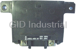
Schneider Electric 31063-409-38 Starter - Coil for Contactor/Starter 120VAC

Scheider Electric BPH0751N5MA2CA1 Motor - 75MM, 1 Stak
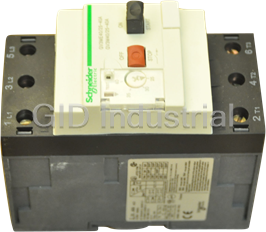
Schneider Electric GV3-M40 - Starter Manual
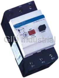
SCHNEIDER ELECTRIC GV3ME40 MANUAL STARTER 600VAC 40AMP IEC
Schneider Electric GV3ME63 Starter - 600VAC 63AMP IEC
SCHNEIDER ELECTRIC-LB1-LD03M61-INTEGRAL STARTER OVERLOAD 575VAC 45-63A
Request a Quote

The quote request has been received
Close

Facing challenges or have inquiries? Feel free to contact us!
Call Us +1-469-283-2440
What they say about us
FANTASTIC RESOURCE
One of our top priorities is maintaining our business with precision, and we are constantly looking for affiliates that can help us achieve our goal. With the aid of GID Industrial, our obsolete product management has never been more efficient. They have been a great resource to our company, and have quickly become a go-to supplier on our list!
Bucher Emhart Glass
EXCELLENT SERVICE
With our strict fundamentals and high expectations, we were surprised when we came across GID Industrial and their competitive pricing. When we approached them with our issue, they were incredibly confident in being able to provide us with a seamless solution at the best price for us. GID Industrial quickly understood our needs and provided us with excellent service, as well as fully tested product to ensure what we received would be the right fit for our company.
Fuji
HARD TO FIND A BETTER PROVIDER
Our company provides services to aid in the manufacture of technological products, such as semiconductors and flat panel displays, and often searching for distributors of obsolete product we require can waste time and money. Finding GID Industrial proved to be a great asset to our company, with cost effective solutions and superior knowledge on all of their materials, it’d be hard to find a better provider of obsolete or hard to find products.
Applied Materials
CONSISTENTLY DELIVERS QUALITY SOLUTIONS
Over the years, the equipment used in our company becomes discontinued, but they’re still of great use to us and our customers. Once these products are no longer available through the manufacturer, finding a reliable, quick supplier is a necessity, and luckily for us, GID Industrial has provided the most trustworthy, quality solutions to our obsolete component needs.
Nidec Vamco
TERRIFIC RESOURCE
This company has been a terrific help to us (I work for Trican Well Service) in sourcing the Micron Ram Memory we needed for our Siemens computers. Great service! And great pricing! I know when the product is shipping and when it will arrive, all the way through the ordering process.
Trican Well Service
GO TO SOURCE
When I can't find an obsolete part, I first call GID and they'll come up with my parts every time. Great customer service and follow up as well. Scott emails me from time to time to touch base and see if we're having trouble finding something.....which is often with our 25 yr old equipment.
ConAgra Foods