

 Manufacturers
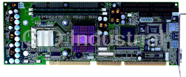
PORTWELL ROBO-882N-VG2

Description
System Host Board | PCI Passive
Part Number
ROBO-882N-VG2
Price
Request Quote
Manufacturer
PORTWELL
Lead Time
Request Quote
Category
Single Board Computers
Specifications
System Chipset
Intel FWH
Form Factor
PICMG 1.0
Ethernet Chipset
Intel 82540EM
Features
- ATI Rage XL VGA controller with 8MB frame buffer memory
- Customized 2U heatsink/FAN for CPU
- Dual Intel 82545EM Gigabit Ethernet controllers
- Intel E7501 chipset
- Intel P64H2 x 1
- Max 8GB DDR SDRAM support, DDR DIMM x4
- Support socket 604 dual Intel Xeon / LV
- Xeon processors with 400/533MHz FSB up to 3.06Ghz
Datasheet

Extracted Text
ROBO-882N-VG2
System Host Board
User's Manual
Copyright © Portwell, Inc., 2003. All rights reserved.
All other brand names are registered trademarks of their respective owners.
Preface
Copyright
This document contains information protected by copyright. No part of this manual may
be reproduced, copied, translated or transmitted in any form or by any means without the
prior written consent from American Portwell Technology, Inc.
Disclaimer
The information in this document is subject to change without prior notice and does not
represent commitment from American Portwell Technology, Inc. However, users may up-
date their knowledge of any product in use by constantly checking its manual posted on
our website: http://www.portewll.com.
American Portwell shall not be liable for direct, indirect, special, incidental, or
consequential damages arising out of the use of any product, nor for any infringements
upon the rights of third parties which may result from such use. Any implied warranties
of merchantability or fitness for any particular purpose is also disclaimed.
Acknowledgements
The ROBO series is a trademark ofAmerican Portwell Technology, Inc. All
other product names mentioned herein are registered trademarks of their respective
owners.
Regulatory Compliance Statements
This section provides the FCC compliance statement for Class A devices and describes
how to keep the system CE compliant.
FCC Compliance Statement for Class A Devices
The product(s) described in this user’s guide has been tested and proved to comply with
the limits for a Class A digital device, pursuant to Part 15 of FCC Rules. These limits are
designed to provide reasonable protection against harmful interference when the equip-
ment is operated in a commercial environment. This equipment generates, uses, and
can radiate radio frequency energy and, if not installed and used in accordance with the
user’s guide, may cause harmful interference to radio communications. Operation of
this equipment in a residential area (domestic environment) is likely to cause harmful
interference, in which case the user will be required to correct the interference (take
adequate measures) at their own expense.
CE Certification
The product(s) described in this user’s guide complies with all applicable European
Union (CE) directives if it has a CE marking.
1
Table of Contents
Chapter 1 General Information..........................................4
1.1 Features....................................................................................5
1.2 Specifications.............................................................................5
1.3 Board Layout..............................................................................8
1.4 Checklist & Mechanical Drawing....................................................9
Chapter 2 Jumper Setting.........................................................10
2.1 Functions of Jumpers..................................................................12
2.2 Setting Jumpers........................................................................13
2.3 Location of Jumpers...................................................................14
2.4 Jumping Setting........ ...............................................................15
Chapter 3 Expansion Capabilities...............................................20
3.1 System Memory.........................................................................21
3.2 Installing DIMM.........................................................................22
3.3 Changing CPU...........................................................................24
3.4 Installing Fan Heatsink.............................................................. 25
Chapter 4 Award BIOS Setup...................................................26
4.1 Entering Setup..........................................................................28
4.2 The Main Menu .........................................................................28
4.3 Getting Help.............................................................................30
4.4 Control Keys.............................................................................31
4.5 Standard CMOS Features.............................................................32
4.6 Advanced BIOS Features.............................................................36
4.7 Advanced Chipset Features.........................................................40
4.8 Integrated Peripherals................................................................41
4.9 Power Management Setup...........................................................43
4.10 PnP/PCI Configurations.............................................................46
4.11 PC Health Status.....................................................................47
4.12 Load Fail-Safe Defaults.............................................................48
4.13 Load Optimized Defaults...........................................................48
4.14 Set Supervisor/User Password....................................................48
4.15 Save & Exit Setup....................................................................49
4.16 Exit Without Saving.................................................................49
2
Chapter 5 Driver Installation .................................................50
5.1 Installing VGA Driver.............................................................51
5.2 Installing INF.......................................................................53
5.3 Installing LAN.......................................................................55
5.4 Installing USB......................................................................57
Appendix: Watchdog Timer Setting..................................................58
Appendix: GPIO User Guide.............................................................62
3
Chapter 1
General Information
Chapter 1
General Information
4
Features
®
. Support socket 604 dual Intel Xeon™ / LV
. Xeon™ processors with 400/533MHz FSB up
to 3.06GHz
. Max. 8GB DDR SDRAM support, DDR DIMM
x 4
®
. Intel E7501 chipsets
®
. Intel P64H2 x 1
. ATI Rage™ XL VGA controller w/8MB frame
buffer memory
®
. Dual Intel 82545EM Gigabit Ethernet control-
lers
. Customized 2U heatsink/FAN for CPU
Specifications
System Architecture
. Full size SBC with 64bit/66MHz PCI/ISA Golden finger
. PCI V2.2 compliant
. PICMG 1.0 (Rev.2.0) compliant
CPU Support
®
. Socket 604 dual Intel Xeon™ / LV Xeon™ processors with 400/533MHz FSB, speed up to 3.06GHz
. On board intelligent switching type power regulator x 2
. Support streaming SIMD instruction
. SMP support is requiring
. Support uni-processor implementation.
. Support Hyper-Threading technology
Main Memory
. DDR SDRAM DIMM x4 support max. memory up to 8GB (DDR200/266)
. Support two 64-bit DDR channels
. Registered/ECC DIMMs only
BIOS
. Award System BIOS
. Plug & Play support
. Advanced Power Management support
. ACPI 2.0 compliant
. 4M bits flash ROM
Chipsets
®
. Intel E7501 chipsets
®
. Intel ICH3-S (82801CA)
®
. Intel P64H2 (82870P2) x1
®
. Intel Firmware Hub (FWH)
. PCI V2.2 compliant
On Board LAN
®
. Dual Intel 82545EM Gigabit Ethernet controllers
. Compliant with PCI V2.1/V2.2, IEEE802.3, IEEE 802.3u, IEEE802.3x, IEEE802.3y, IEEE802.3ab
. WfM 2.0, PC2001 compliant
. RJ45 with LED connector x 2
5
On Board VGA
. ATI Rage™ XL with 8MB frame buffer memory
. Fully PC 98 and PC 99 Compliant
. 15 pin CRT connector x 1
On Chip I/O (ICH3-S)
. On board USB port x 4
. SMBus 2.0 controller
. FWH interface
. LPC interface
. AC’ 97 2.0 interface
. PCI 2.2 interface
. USB 1.1 compliant
. Integrated System Management Controller
On Board Super I/O
. Onboard ITE 8712F-A super I/O
. SIO x 2, with 2 x 16C550 UARTs, 10 pin header x 2
. PIOx 1, bi-directional, EPP/ECP support, 26 pin connector x1
. Floppy Disk controller: 34 pin connector x 1
. 6 pin mini DIN connector x 1, for PS/2 keyboard/mouse, 5 pin connector x 1
(for external keyboard)
. On Board buzzer x 1
. GPIO (4 in 4 out )
. On board 2 pin header for I2C;
. On Board 2 pin header for reset SW / 2 pin for IDE active LED / 2 pin ATX power SW
. One 3 pins power header for 3 pins Power Cable connect to Backplane Board
to support ATX Power On function.
. On board 4 Pin Additional Power Source Input
. AC97 output, 10 pin header x 1
System Monitor
. Derived from Super IO ITE 8712F-A to support system monitor.
. 8 voltage (For+1.5V, +3.3V, +5V, -5V, +12V, -12V, Vcore and Vcc5VStand-By)
. One Fan speed for CPU ;Temperature x 2 (one for CPU internal use, another for external system use)
ACPI Function
( only when 3 pins Power cable connect to Backplane which connect with ATX Power Source )
. Soft Power off
. Power-on by Keyboard
. Wake-up by LAN
. Wake-up by Ring
Real Time Clock
. On chip RTC with battery back up
. External Li Battery x 1
Watchdog Timer
. Watchdog timeout can be programmable by Software from 1,2,4,8,16,32,…...256 seconds
. Reserved 32 bit PCI interface for Portwell EBK module
. PCI to ISA Bridge & ISAMAX Support
. ITE 8888F x 1 PCI to ISA Bridge
. Provide 64mA high driving capability to maximize ISA signals for support ISA cards up to 20 on the backplane ISA Slot.
Dimensions
. 338.58mm(L) x 122mm(W)
13.3”(L) x 4.8”(W)
Customized Heatsink/FAN
. Customized heatsink/FAN to cover dual processors
. Height: 2U
6
Power Requirements
Voltage Maximum
+5V 25A
+12V 20A
Environments
. Operating temperatures: 0°C to 60°C
(0°C to 50°C for 2.8GHz CPU)
. Storage temperatures: -20°C to 80°C
. Relative humidity: 10% to 90%
(Non-condensing)
Certification
.CE
. FCC
7
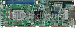
1.3 Board Layout
Max.8GB DDR 266/Dual channel
memory in 4 DIMM Slots
VGA Port
Dual LAN
®
®
Intel E7501 Chipset
Intel P64H2 64bit
PCI-X Bridge Intel 82545EM
® Gigabit Ethernet
TM TM
Dual Intel Xeon /LV Xeon
w/533MHz FSB Speed to 3.06GHz+
®
Intel ICH3
ATI Rage XL VGA Chipset
Figure 1-1: Birdeye’s View of ROBO-882N-VG2
8
1.4 Checklist
After opening the package of the ROBO-882N-VG2, please check and make sure
you have all of the following items:
��� One ROBO-882N-VG2 SBC
��
(A mechanical drawing of this model is shown below.)
��� One ROBO-882N-VG2 Quick Reference Guide
��
��� One 50CM Cable JST 2.5mm 3 pin to 3 pin (5V standby ATX Power-on
��
Cable)
��� One Y Cable for Keyboard and Mouse
��
��� One 180 mm AUX Power Cable (for J2)
��
��� One Cable Set (FDD x1, SIO+PIO x1, SIO x1/Keyboard x1/IDE66 x1)
��
��� One USB Cable with Bracket
��
��� One Driver Manual CD
��
Figure 1-2: Mechanical Drawing of ROBO-882N-VG2
9
Chapter 2
Jumper & Switch Settings
10
This chapter of the User’s Manual describes how to set jumpers.
Before You Begin
Ensure you have a stable, clean working environment. Dust and dirt can get into components and cause a
malfunction. Use containers to keep small components separated.
Adequate lighting and proper tools can prevent you from accidentally damaging the internal components.
Most of the procedures that follow require only a few simple tools, including the following:
� A Philips screwdriver
� A flat-tipped screwdriver
� A set of jewelers Screwdrivers
����� A grounding strap
� An anti-static pad
Using your fingers can disconnect most of the connections. It is recommended that you do not use needle-
nosed pliers to disconnect connections as these can damage the soft metal or plastic parts of the
connectors.
Before working on internal components, make sure that the power is off. Ground yourself before touching any
internal components, by touching a metal object. Static electricity can damage many of the electronic
components. Humid environment tend to have less static electricity than dry environments. A grounding
strap is warranted whenever danger of static electricity exists.
Precautions
Computer components and electronic circuit boards can be damaged by discharges of static electricity.
Working on the computers that are still connected to a power supply can be extremely dangerous. Follow
the guidelines below to avoid damage to your computer or yourself.
� Always disconnect the unit from the power outlet whenever you are working inside the case.
� If possible, wear a grounded wrist strap when you are working inside the computer case. Alternatively,
discharge any static electricity by touching the bare metal chassis of the unit case, or the bare metal
body of any other grounded appliance.
� Hold electronic circuit boards (such as the ROBO-882N-VG2 board) by the edges only. Do not touch the
components on the board unless it is necessary to do so. Don’t flex or stress the circuit board.
� Leave all components inside the static-proof packaging that they shipped with until they are ready for
installation.
� Use correct screws and do not over tighten screws.
11
2.1 Functions of Jumpers
You can use jumpers to set configuration options. The table below defines
function of each jumper:
Jumper Function Jumper Function
J1,J2 Power Connector JP1 Speaker
J4,J5 Fan Connector JP3 GPIO
J5 on
Daughter ATX Power JP4 On-board RTC
Board
J6 AC’97 JP5 SMBUS
J7 IDE Active LED JP6 Reset Button
J13 AT/ATX Selection JP7 Power Button
JP9 Keyboard Lock
Table 2-1: Functions of Jumpers
12
2.2 Setting Jumpers
A jumper is the simplest kind of electric switch. It consists of two metal pins and a
cap. When setting the jumpers, ensure that the jumper caps are placed on the
correct pins. When the jumper cap is placed on both pins, the jumper is SHORT.
If you remove the jumper cap, or place the jumper cap on just one pin, the jumpr is
OPEN. Please see the following illustrations:
The illustrations on the right show
a 2-pin jumper. When the jumper
cap is placed on both pins, the
jumper is SHORT. If you remove
the jumper cap, or place the
jumper cap on just one pin, the
jumper is OPEN. Open (Off) Short (On)
These illustrations show a 3-pin
jumper. Pins 1 and 2 are SHORT.
Figure 2-1 : How to Set Jumpers
13
Secondary IDE
Primary IDE
Floppy Disk
PIO
2.3 Location of Jumpers
The illustration below shows the location of the mainboard jumpers:
J1
* Channel A DIMM 1
J2 Channel B DIMM 2
Channel B DIMM 4
*
*
JP4
Primary Secondary JP7
J5
JP9
CPU Socket CPU Socket
J13
*
*
* *
**
J6
*
JP6
** JP3
SIO1
*
*
SIO2
*
J7
* *
J4 JP1 JP5
J5
= Pin 1
*
USB Connectors
PS/2 KB/Mouse VGA Connector
LAN Connectors
Figure 2-2 : Location of Jumpers
14
2.4 Jumper Setting
Mainboard
15
Daughterboard
16
(daughterboard)
17
18
19
Chapter 3
Expansion Capabilities
20
3.1 System Memory
Your system memory is provided by DIMM’s (Dual In-line Memory Modules) on the
CPU board. The CPU board contains two memory banks: Bank 0 and 1, correspond-
ing to connector DIMM1, DIMM2.
The table below shows possible DIMM configurations for the memory banks.
Please be noted that the ROBO-882N-VG2 supports 8 GB DDR SDRAM. Configura-
tions using different brands of memory modules are not recommended.
DIMM1 DIMM3 DIMM2 DIMM4
Total Memory
Channel A Channel A Channel B Channel B
128MB Empty Empty 256MB
128MB
256MB Empty Empty 512MB
256MB
512MB Empty Empty 1024MB
512MB
1024MB Empty Empty 2048MB
1024MB
Empty 128MB 128MB 256MB
Empty
Empty 256MB 256MB 512MB
Empty
Empty 512MB 512MB 1024MB
Empty
Empty 1024MB 1024MB 2048MB
Empty
128MB 128MB 128MB 512MB
128MB
256MB 256MB 256MB 1024MB
256MB
512MB 512MB 512MB 2048MB
512MB
1024MB 1024MB 1024MB 4096MB
1024MB
2048MB 2048MB 2048MB 2048MB 8192MB
Table 3-1 : ROBO-882N-VG2 DIMM Configurations
21
3.2 Installing DIMM
To install DIMM:
1. Make sure the two handles of the DIMM sockets are in the “open” position, i.e.
the handles stay outward.
Figure 3-1 : How to Install DIMM (1)
2. Slowly slide the DIMM modules along the plastic guides in the both ends of the
socket.
Figure 3-2 : How to Install DIMM (2)
22
3. Then press the DIMM module down right into the socket, until a click is heard.
That means the two handles automatically locked the memory modules into the
right position of the DIMM socket.
Figure 3-3 : How to Install DIMM (3)
4. To take away the memory module, just push the both handles outward, the
memory module will be ejected by the mechanism in the socket.
Figure 3-4 : How to Install DIMM (4)
23
3.3 Changing CPU
To change the CPU:
1. Pull the handling bar of the socket upward to the other end to loosen the
socket’s openings. Carefully lift the existing CPU up to remove it from the socket.
2. Place the new CPU on the middle of the socket, orienting its beveled corner to
line up with the socket’s beveled corner. Make sure the pins of the CPU fit evenly
to the socket openings. Replace the handling bar to fasten the CPU to the socket.
Figure 3-5 : How to Change CPU
24
3.4 Installing the Fan Heatsink
Step 1
Insert the fan in the CPU bed.
Step 2
As shown in the picture, screw tight.
Step 3
Then get the fan connector connected.
25
Chapter 4
Award BIOS Setup
26
This chapter explains how to use the BIOS Setup program for the ROBO-882N-VG2.
The current BIOS setup pictures in the chapter is for reference only, which may change
by the BIOS modification in the future. User can download any major updated items
from Portwell web site http://www.portwell.com. If any unclear message occurs,
please contact Portwell customer service representative for help or log onto http://
www.portwell.com.
About the BIOS
The BIOS (Basic Input and Output System) Setup program is a menu driven utility that
enables you to make changes to the system configuration and tailor your system to
suit your individual work needs. It is a ROM-based configuration utility that displays the
system’s configuration status and provides you with a tool to set system parameters.
These parameters are stored in non-volatile battery-backed-up CMOS RAM that
saves this information even when the power is turned off. When the system is turned
back on, the system is configured with the values found in CMOS.
With easy-to-use pull down menus, you can configure such items as:
� Hard drives, diskette drives, and peripherals
� Video display type and display options
� Password protection from unauthorized use
� Power management features
When to Run BIOS
This program should be executed under the following conditions:
� When changing the system configuration
� When a configuration error is detected by the system and you are prompted to
make changes to the Setup program
� When resetting the system clock
� When setting the CPU clock speed so that it automatically runs either fast or slow
� When redefining the communication ports to prevent any conflicts
� When making changes to the Power Management configuration
� When changing the password or making other changes to the security setup
Normally, CMOS setup is needed when the system hardware is not consistent with the
information contained in the CMOS RAM, whenever the CMOS RAM has lost power,
or the system features need to be changed.
27
4.1 Entering Setup
When the system is powered on, the BIOS will enter the Power-On Self Test (POST)
routines. These routines perform various diagnostic checks; if an error is encountered,
the error will be reported in one of two different ways:
� If the error occurs before the display device is initialized, a series of beeps will be
transmitted.
� If the error occurs after the display device is initialized, the screen will display the
error message.
Powering on the computer and immediately pressing allows you to enter Setup.
Another way to enter Setup is to power on the computer and wait for the following
message during the POST:
TO ENTER SETUP BEFORE BOOT
PRESS KEY
Press the key or press the
Frequently asked questions
How does Industrial Trading differ from its competitors?

Is there a warranty for the ROBO-882N-VG2?
Which carrier will Industrial Trading use to ship my parts?
Can I buy parts from Industrial Trading if I am outside the USA?
Which payment methods does Industrial Trading accept?
Why buy from GID?

Quality
We are industry veterans who take pride in our work

Protection
Avoid the dangers of risky trading in the gray market

Access
Our network of suppliers is ready and at your disposal

Savings
Maintain legacy systems to prevent costly downtime

Speed
Time is of the essence, and we are respectful of yours
Related Products

Portwell 14-4277720 CPU Board. BOARD PEB-2772VGATM 3.5" Atom D2550 | 1.86GHz | Mini PCIe slot | 4GB/...
Portwell 216005080042 CPU Board - Intel Pentium Processor Based Half-Sized ISA CPU
Request a Quote

The quote request has been received
Close

Facing challenges or have inquiries? Feel free to contact us!
Call Us +1-469-283-2440
What they say about us
FANTASTIC RESOURCE
One of our top priorities is maintaining our business with precision, and we are constantly looking for affiliates that can help us achieve our goal. With the aid of GID Industrial, our obsolete product management has never been more efficient. They have been a great resource to our company, and have quickly become a go-to supplier on our list!
Bucher Emhart Glass
EXCELLENT SERVICE
With our strict fundamentals and high expectations, we were surprised when we came across GID Industrial and their competitive pricing. When we approached them with our issue, they were incredibly confident in being able to provide us with a seamless solution at the best price for us. GID Industrial quickly understood our needs and provided us with excellent service, as well as fully tested product to ensure what we received would be the right fit for our company.
Fuji
HARD TO FIND A BETTER PROVIDER
Our company provides services to aid in the manufacture of technological products, such as semiconductors and flat panel displays, and often searching for distributors of obsolete product we require can waste time and money. Finding GID Industrial proved to be a great asset to our company, with cost effective solutions and superior knowledge on all of their materials, it’d be hard to find a better provider of obsolete or hard to find products.
Applied Materials
CONSISTENTLY DELIVERS QUALITY SOLUTIONS
Over the years, the equipment used in our company becomes discontinued, but they’re still of great use to us and our customers. Once these products are no longer available through the manufacturer, finding a reliable, quick supplier is a necessity, and luckily for us, GID Industrial has provided the most trustworthy, quality solutions to our obsolete component needs.
Nidec Vamco
TERRIFIC RESOURCE
This company has been a terrific help to us (I work for Trican Well Service) in sourcing the Micron Ram Memory we needed for our Siemens computers. Great service! And great pricing! I know when the product is shipping and when it will arrive, all the way through the ordering process.
Trican Well Service
GO TO SOURCE
When I can't find an obsolete part, I first call GID and they'll come up with my parts every time. Great customer service and follow up as well. Scott emails me from time to time to touch base and see if we're having trouble finding something.....which is often with our 25 yr old equipment.
ConAgra Foods