

 Manufacturers
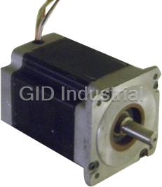
PACIFIC SCIENTIFIC R22HENA-R1-NS-NV-01

Description
Pacific Scientific R22HENA-R1-NS-NV-01 Servo Motor - (low inertia, rate earth magnet)
Part Number
R22HENA-R1-NS-NV-01
Price
Request Quote
Manufacturer
PACIFIC SCIENTIFIC
Lead Time
Request Quote
Category
Servo Motor
Datasheet

Extracted Text
DIMENSIONS* . 281 DIA. 5. 25 7 .11 133.35 .625 DIA . 8. 75 .50 .25 2.25 15. 87 222. 25 1.270 6.35 57.15 .38 9. 65 15. 75 16. 75 400. 05 425. 45 MTG. 14. 50 368. 30 GROUND STUD 0. 75 0.28 19. 05 7.11 CLEARANCE SPACE 1.25 FOR CONNECTORS AND 1. 50 2. 50 LEAD DRESS 37 1.5 38. 10 63. 50 MTG. TYP. SC752/SC753 9.00 1.25 10.63 .38 228.60 31.75 270.00 9.65 15.75 16.75 400.05 425.45 MTG. 14.50 368.3 .75 .28 19.05 2.00 5.00 7.11 CLEARANCE SPACE FOR 50.80 127.00 TYP. CONNECTORS AND LEAD DRESS MTG. TYP. SC754/SC755 18.00 1.25 .38 10.60 457.20 31.75 9.65 269.24 23.88 606.55 21.63 23.00 549.4 584.20 MTG. 0.75 .28 7.50 19.05 7.11 190.50 TYP. MTG. TYP. CLEARANCE SPACE FOR 1.50 CONNECTORS AND LEAD 15.00 DRESS 38.10 381.00 MTG. TYP. SC756 *See pages B-6 through B-26 for information on the next generation Servo Position Control. Brushless Servo Systems B-29 GENERAL . . .SC750 Series Controllers* Efficiency (50% output voltage, rated cont. current) . . . . . . . . . . . . . . .>95% Form factor . . . . . . . . . . . . . . . . . . . . . . . . . . . . . . . . . . . . . . . . . . . . .<1.01 Current loop bandwidth . . . . . . . . . . . . . . . . . . . . . . . . . . . . . . . . . . . .1500 to 3000Hz Input command . . . . . . . . . . . . . . . . . . . . . . . . . . . . . . . . . . . . . . . . .RS-232 or RS-485/422, PacLAN port Output ripple frequency (±15%) . . . . . . . . . . . . . . . . . . . . . . . . . . . . .20 kHz Position resolution . . . . . . . . . . . . . . . . . . . . . . . . . . . . . . . . . . . . . . .65,536 steps/rev (16 bit) Position accuracy (drive only) Standard . . . . . . . . . . . . . . . . . . . . . . . . . . . . . . . . . . . . . . . . . . .± 22 arcmin Optional . . . . . . . . . . . . . . . . . . . . . . . . . . . . . . . . . . . . . . . . . . .± 4 arcmin Velocity range (drive only) . . . . . . . . . . . . . . . . . . . . . . . . . . . . . . . . .0 to 12,000 RPM Analog input . . . . . . . . . . . . . . . . . . . . . . . . . . . . . . . . . . . . . . . . . . . .±12 Vdc range, 16 bit @200 Hz bandwidth or 14 bit @1000 Hz bandwidth, 0.25% linearity, 50mV/°C drift, fully monotonic, 60 mV offset, 100 Kohm input impedance Analog output . . . . . . . . . . . . . . . . . . . . . . . . . . . . . . . . . . . . . . . . . . .±5 Vdc range, 12 bit, updated every 0.4 mS, fully monotonic, 50 ohm source impedance Control inputs . . . . . . . . . . . . . . . . . . . . . . . . . . . . . . . . . . . . . . . . . . .Enable Fault reset Inhibit + Inhibit - Control outputs . . . . . . . . . . . . . . . . . . . . . . . . . . . . . . . . . . . . . . . . . .Fault Current monitor Commutation signal Two +5V @250 mA max. Programmable inputs . . . . . . . . . . . . . . . . . . . . . . . . . . . . . . . . . . . . .12 general purpose 2 general purpose/fast 2 general purpose/counter Optically isolated, 5 to 24 Vdc logic, sourcing; fast inputs have 5mS max. capture time Programmable outputs . . . . . . . . . . . . . . . . . . . . . . . . . . . . . . . . . . . .11 general purpose 1 general purpose/PWM 5 to 24 Vdc logic, open collector sinking, up to 100 mA Encoder Emulation Modes . . . . . . . . . . . . . . . . . . . . . . . . . . . . . . . . . . . . . . . . . . . .Encoder output Encoder input Step/direction input Encoder output mode . . . . . . . . . . . . . . . . . . . . . . . . . . . . . . . . .Quadrature with marker pulse, differential TTL line driver, software selectable resolution—500, 512, 1000, 1024, 2000, 2048, 4096, 16,384 PPR, 750 kHz max. Encoder input mode . . . . . . . . . . . . . . . . . . . . . . . . . . . . . . . . . .Quadrature with marker pulse, differential TTL line receivers, 750 kHz max. Step/direction mode . . . . . . . . . . . . . . . . . . . . . . . . . . . . . . . . . .Differential TTL line receivers, 750 kHz max. Mating connectors (furnished) . . . . . . . . . . . . . . . . . . . . . . . . . . . . . . .All plug-in mating connectors Storage temperature . . . . . . . . . . . . . . . . . . . . . . . . . . . . . . . . . . . . . .-55°C to 70°C Operating temperature Full ratings . . . . . . . . . . . . . . . . . . . . . . . . . . . . . . . . . . . . . . . . .0°C to 50°C Derated . . . . . . . . . . . . . . . . . . . . . . . . . . . . . . . . . . . . . . . . . .50°C to 60°C Altitude . . . . . . . . . . . . . . . . . . . . . . . . . . . . . . . . . . . . . . . . . . . . . . .5000 ft. (1500 m) Humidity . . . . . . . . . . . . . . . . . . . . . . . . . . . . . . . . . . . . . . . . . . . . . . .10% to 90%, non-condensing Weight . . . . . . . . . . . . . . . . . . . . . . . . . . . . . . . . . . . . . . . . . . . . . . . .SC752, 13 lbs. SC753, 16 lbs. SC754/755, 40 lbs SC756, 90 lbs. Linearly derate the continuous current and power ratings to 70% at 60°C. *See pages B-6 through B-26 for information on the next generation Servo Position Control. B-30 Brushless Servo Systems POWER DATA. . .SC750 Series Controllers* SC752 SC753 SC754 SC755 SC756 Input voltage Control logic power . . . . . . . . . . . . . . . . . . . . . . . 90 to 264 Vac, 47 to 63 Hz, 1 phase Bus power . . . . . . . . . . . . . . . . . . . . . . . . . . . . . . 120 Vac (+ 10%, -15%)/ 240 Vac (+ 10%, -15%), 240 Vac (+ 10%, -15%), 47 to 63 Hz, 3 phase 47 to 63 Hz, 1 or 3 phase Bus Voltage (with 240 Vac input) . . . . . . . . . . . . . . . . . . . . . . . 320 Vdc (with 120 Vac input) . . . . . . . . . . . . . . . . . . . . . . . 160 Vdc Input current Control logic power . . . . . . . . . . . . . . . . . . . . . . . 500 mA max. @ 115 Vac, 250 mA max. @ 230 Vac. Bus current (RMS) (230 Vac, 3-phase) . . . . . . . . . . . . . . . . . . . . . . 4.5 A 9 A 18 A 29 A (@6kW) 38 A (@ 12kW) rms rms rms rms rms o Output current @ 50 C Peak (5 seconds) . . . . . . . . . . . . . . . . . . . . . . . . . 7.5 A 15 A 30 A 60 A 120 A Continuous (stall) . . . . . . . . . . . . . . . . . . . . . . . . . 3.8 A 7.5 A 15 A 30 A 60 A o Output power (min. @ 50 C) Peak (5 seconds) 230 Vac, 3-phase . . . . . . . . . . . . . . . . . . . . . . . 2.2 kW 4.5 kW 9 kW 18 kW 36 kW 230 Vac, 1-phase . . . . . . . . . . . . . . . . . . . . . . . 2.0 kW 4.0 kW n/a n/a n/a Continuous 230 Vac, 3-phase . . . . . . . . . . . . . . . . . . . . . . . 1.1 kW 2.2 kW 4.5 kW 9 kW 18 kW 230 Vac, 1-phase . . . . . . . . . . . . . . . . . . . . . . . 0.8 kW 1.6 kW n/a n/a n/a Shunt regulator power Peak . . . . . . . . . . . . . . . . . . . . . . . . . . . . . . . . . . 3 kW 6 kW 20 kW 20 kW 40 kW Continuous . . . . . . . . . . . . . . . . . . . . . . . . . . . . . . 20 W 40 W 200 W 200 W 500 W Currents shown are the peak of a sinewave. Multiply by 0.707 to get RMS current value. The SC755 can be configured for 40 A continuous (stall). Input current is specified with unit operating at continuous rated output power. *See pages B-6 through B-26 for information on the next generation Servo Position Control. Brushless Servo Systems B-31 SC750 SERIES RECOMMENDED MOTOR/CONTROLLER SYSTEMS* Peak Peak Cont. Cont. Inertia Servo- -3 stall rated stall rated Rated x 10 motor Servo- Inductance 2 torque torque torque torque Speed lb-in-S / Dia. or motor line-line Servo- Servo- 2 T T T T W kgm Width/height Length L motor Controller PS PR CS CR R lb-in./Nm lb-in./Nm lb-in./Nm lb-in./Nm rpm J inch/mm inch/mm mH model model With R Series (low inertia, rare earth magnet) motors 10/ 1.1 6.5/ .7 4.8/ .5 2.5/ .3 8000 0.12/ .014 2.00/ 50.8 7.38/187.5 5.3 R22HENA-R1-NS-NV-01 SC752A-001-01 14/ 1.6 8/ .9 7.6/ .9 5.2/ .6 8000 0.15/ .017 2.00/ 50.8 8.38/212.9 6.5 R23HENA-R1-NS-NV-01 SC752A-001-01 17/ 1.9 10/ 1.1 9.2/ 1.0 7.1/ .8 6000 0.18/ .020 2.00/ 50.8 9.38/238.3 6.5 R24HENA-R1-NS-NV-01 SC752A-001-01 27/ 3.0 25/ 2.8 14/ 1.6 10/ 1.1 4000 0.55/ .062 3.25/ 82.6 7.09/180.1 23.0 R32GENC-R2-NS-NV-00 SC752A-001-01 27/ 3.0 25/ 2.8 14/ 1.6 6/ .7 7000 0.55/ .062 3.25/ 82.6 7.09/180.1 5.8 R32HENC-R2-NS-NV-00 SC753A-001-01 36/ 4.0 33/ 3.7 21/ 2.4 16/ 1.8 3000 0.74/ .084 3.25/ 82.6 8.09/205.5 22.0 R33GENC-R2-NS-NV-00 SC752A-001-01 36/ 4.0 25/ 2.8 21/ 2.4 10/ 1.1 6000 0.74/ .084 3.25/ 82.6 8.09/205.5 5.6 R33HENC-R2-NS-NV-00 SC753A-001-01 45/ 5.0 42/ 4.7 27/ 3.0 24/ 2.7 2800 0.92/ .104 3.25/ 82.6 9.09/230.9 30.0 R34JENC-R2-NS-NV-00 SC752A-001-01 45/ 5.0 38/ 4.3 27/ 3.0 16/ 1.8 4000 0.92/ .104 3.25/ 82.6 9.09/230.9 7.5 R34KENC-R2-NS-NV-00 SC753A-001-01 54/ 6.0 53/ 5.9 32/ 3.6 30/ 3.4 2000 1.11/ .125 3.25/ 82.6 10.09/256.3 42.0 R35JENC-R2-NS-NV-00 SC752A-001-01 54/ 6.0 48/ 5.4 32/ 3.6 23/ 2.6 3000 1.11/ .125 3.25/ 82.6 10.09/256.3 10.5 R35KENC-R2-NS-NV-00 SC753A-001-01 66/ 7.4 50/ 5.6 33/ 3.7 33/ 3.4 1800 1.90/ .215 4.25/108.0 8.34/211.8 53.0 R43GENA-R2-NS-NV-00 SC752A-001-01 66/ 7.4 60/ 6.7 33/ 3.7 31/ 3.5 3000 1.90/ .215 4.25/108.0 8.34/211.8 13.3 R43HENA-R2-NS-NV-00 SC753A-001-01 106/11.9 95/10.6 48/ 5.4 46/ 5.2 2000 2.70/ .305 4.25/108.0 9.84/249.9 4.9 R45GENA-R2-NS-NV-00 SC753A-001-01 106/11.9 95/10.6 48/ 5.4 43/ 4.8 4000 2.70/ .305 4.25/108.0 9.84/249.9 20.0 R45HENA-R2-NS-NV-00 SC754A-001-01 142/15.9 120/13.4 64/ 7.2 61/ 6.8 1500 3.50/ .395 4.25/108.0 11.34/288.1 25.0 R46GENA-R2-NS-NV-00 SC753A-001-01 142/15.9 120/13.4 64/ 7.2 50/ 5.6 3000 3.50/ .395 4.25/108.0 11.34/288.1 6.2 R46HENA-R2-NS-NV-00 SC754A-001-01 150/16.8 125/14.0 70/ 7.8 58/ 6.5 3000 7.10/ .818 5.75/146.1 9.36/237.7 8.9 R63GENA-R2-NS-NV-00 SC754A-001-01 150/16.8 142/15.9 70/ 7.8 38/ 4.3 6000 7.10/ .818 5.75/146.1 9.36/237.7 2.2 R63HENA-R2-NS-NV-00 SC755A-001-01 240/26.9 230/25.8 115/12.9 102/11.4 1700 11.10/1.28 5.75/146.1 11.36/288.5 13.7 R65GENA-R2-NS-NV-00 SC754A-001-01 240/26.9 200/22.4 115/12.9 90/10.1 3000 11.10/1.28 5.75/146.1 11.36/288.5 3.4 R65HENA-R2-NS-NV-00 SC755A-001-01 340/38.1 305/34.2 168/18.8 156/17.5 1000 15.10/1.74 5.75/146.1 13.36/339.3 18.2 R67GENA-R2-NS-NV-00 SC754A-001-01 340/38.1 330/37.0 168/18.8 146/16.4 2000 15.10/1.74 5.75/146.1 13.36/339.3 4.6 R67HENA-R2-NS-NV-00 SC755A-001-01 300/33.6 280/31.4 190/21.3 125/14.0 3800 39.10/4.50 7.50/190.5 10.93/277.6 3.2 R84GENA-R2-NS-NV-00 SC755A-001-01 300/33.6 270/30.2 190/21.3 45/ 5.0 6000 39.10/4.50 7.50/190.5 10.93/277.6 0.8 R84HENA-R2-NS-NV-00 SC756A-001-01 410/45.9 395/44.2 276/30.1 225/25.2 2000 58.10/6.69 7.50/190.5 12.93/328.4 3.6 R86GENA-R2-NS-NV-00 SC755A-001-01 410/45.9 365/40.9 276/30.1 120/13.4 4000 58.10/6.69 7.50/190.5 12.93/328.4 0.9 R86HENA-R2-NS-NV-00 SC756A-001-01 540/60.5 525/58.8 357/28.8 325/36.4 1500 76.10/8.77 7.50/190.5 14.93/379.2 4.0 R88GENA-R2-NS-NV-00 SC755A-001-01 540/60.5 500/56.0 357/28.8 205/23.0 3000 76.10/8.77 7.50/190.5 14.93/379.2 1.0 R88HENA-R2-NS-NV-00 SC756A-001-01 800/89.6 730/81.8 451/50.5 424/47.5 1200 95.10/10.96 7.50/190.5 16.93/430.0 7.4 R8AGENA-R2-NS-NV-00 SC755A-001-01 800/89.6 720/80.6 451/50.5 300/33.6 2000 95.10/10.96 7.50/190.5 16.93/430.0 1.9 R8AHENA-R2-NS-NV-00 SC756A-001-01 With F Series (medium inertia, ferrite magnet) motors 56/ 6.3 34/ 3.8 32/ 3.6 25/ 2.8 1500 9.20/1.04 4.25/108.0 8.34/211.8 49.0 F43GENA-R2-NS-NV-00 SC752A-001-01 60/ 6.7 30/ 3.4 32/ 3.6 22/ 2.5 3000 9.20/1.04 4.25/108.0 8.34/211.8 12.0 F43HENA-R2-NS-NV-00 SC753A-001-01 84/ 9.4 55/ 6.2 46/ 5.2 43/ 4.8 1000 13.70/1.55 4.25/108.0 9.84/249.9 69.0 F45FENA-R2-NS-NV-00 SC752A-001-01 84/ 9.4 45/ 5.0 46/ 5.2 38/ 4.3 2000 13.70/1.55 4.25/108.0 9.84/249.9 17.0 F45GENA-R2-NS-NV-00 SC753A-001-01 121/13.6 62/ 6.9 61/ 6.8 48/ 5.4 1500 17.70/2.00 4.25/108.0 11.34/288.1 24.0 F46GENA-R2-NS-NV-00 SC753A-001-01 121/13.6 60/ 6.7 61/ 6.8 43/ 4.8 3000 17.70/2.00 4.25/108.0 11.34/288.1 6.0 F46HENA-R2-NS-NV-00 SC754A-001-01 See page B-73 for definitions of ratings. Peak torque ratings are for 5 seconds. Rated speeds are for 230 Vac, 3 phase operation. Derate to approximately 85% for 240 Vac, 1 phase operation. Derate to 40% for 115 Vac, 1 phase operation. Includes primary feedback inertia. Controller model numbers are for 12 bit resolution option. See "How to Order" on page B-34. Each system requires one feedback and one motor power cable. *See pages B-6 through B-26 for information on the next generation Servo Position Control. B-32 Brushless Servo Systems CONNECTION DIAGRAM . . . SC750 Series Controllers* SYSTEM STATUS DISPLAY 0 - NOT ENABLED, NO FAULT 1 - RESOLVER CONVERSION FAULT 2 - MOTOR OVERTEMPERATURE 3 - CONTROLLER OVERTEMPERATURE 4 - IT FAULT 5 - LINE- NEUTRAL FAULT 2 AC CTRL SWITCH 6 - LOGIC SUPPLY UNDERVOLTAGE 1 2 3 4 5 6 7 8 9 INT EXT 7 - OUTPUT OR BUS OVERCURRENT 8 - ENABLED, NO FAULT J57 INHIBIT + 1 INHIBIT - 2 1 + 5 VDC FAULT RESET 3 2 CH A OUT: CH A IN (STEP +) ENABLE 4 3 CH A OUT: CH A IN (STEP -) FAULT 5 J53 4 CH B OUT: CH B IN (DIR +) OUTPUT 1 6 5 CH B OUT: CH B IN (DIR - ) J52 OUTPUT 2 7 6 SHIELD (I/O RTN) OUTPUT 3 8 7 CH Z OUT: CH Z IN OUTPUT 4 9 8 CH Z OUT: CH Z IN I/O RTN 10 9 + 5 VDC RTN/I/O RTN 120/240 VAC LI I/O RTN 1 1 1 120/240 VAC L2 AC POWER OUTPUT 5 2 2 240 VAC L3 47 - 63 Hz OUTPUT 6 3 3 CHASSIS GND OUTPUT 7 4 J3 4 CTL LOGIC AC 1 OUTPUT 8 5 5 J54 SC750 CTL LOGIC AC 2 OUTPUT 9 6 6 OUTPUT 10 7 SERIES GROUND OUTPUT 11 8 STUD OUTPUT 12/PWM 9 I/O RTN 10 2 - BUS 1 J2 2 INT R/EXT R 3 INT R INPUT 1 1 4 + BUS/EXT R INPUT 2 2 JUMPER SUPPLIED INPUT 3 3 D CASE GND INPUT 4 4 1 C PHASE T INPUT 5 5 J55 2 INPUT 6 6 B PHASE S 3 INPUT 7/REG 1 7 J1 A PHASE R 4 INPUT 8/REG 2 8 + DC A (USER POWER SUPPLY) 9 MOTOR - DC A (USER POWER SUPPLY) 10 D S1 1 B S3 2 S2 C INPUT 9 1 3 S4 INPUT 10 A 2 4 INPUT 11 3 J51 5 INPUT 12 R1 4 E 6 INPUT 13 5 F R2 J56 INPUT 14 7 6 RESOLVER G PTC INPUT 15/CNTR RST 7 8 H PTC RTN INPUT 16/CNTR CLK 8 9 + DC B (USER POWER SUPPLY) 9 J58 PTC - DC B (USER POWER SUPPLY) 10 1 2 3 4 5 6 7 8 9 PACIFIC SCIENTIFIC BRUSHLESS MOTOR NOTES: DASHED LINES REPRESENT EXTERNAL CONNECTIONS 1 ON THE SC752/753 (THESE CONNECTIONS ARE REQUIRED) EXTERNAL CONNECTIONS ARE ESTABLISHED USING THE 2 AC SWITCH ON THE SC754/755/756 *See pages B-6 through B-26 for information on the next generation Servo Position Control. Brushless Servo Systems B-33 ANALOG IN (+) ANALOG IN (-) + 5 VDC RTN/SHIELD ANALOG OUT TXD 232 CURRENT MONITOR RXD 232 HALL SIGNAL 3 + 5 VDC I/O RTN COMMON LAN + TXD (+) 485 LAN - TXD (-) 485 LAN SHIELD RXD (+) 485 RXD (-) 485 HOW TO ORDER . . . SC750 Series Controllers* To order an SC750 Series brushless servo motor controller, designate the power level and position accuracy desired. The next three digits are a controller customization code, which is factory assigned. It is also used to specify any customer requested modifications. The final two digits specify the desired software option. For a standard SC750 Series controller with a power rating of 15A cont., 30A peak, the following model number would be ordered: MODEL NUMBER CODE SC 7 5 4 A-001-01 Servo controller Series Function code 5=position controller (resolver) Power level code 2=3.8A cont./7.5A peak 3=7.5A cont./15A peak 4=15A cont./30A peak 5=30A cont./60A peak 6=60A cont./120A peak Option code A=12 bit RDC (±22 arcmin, 1024 ppr) B=14 bit RDC (±4 arcmin, 4096 ppr) Customization code Factory assigned, 001=standard unit Suffix code -01=PacSci ServoBASIC Plus™ programming language with 24K user memory -02=PacSci ServoBASIC Plus™ programming language with 100K user memory and faster processor HOW TO ORDER . . .SC750 Series Recommended Motor/Controller Systems See the Recommended Motor/Controller Systems table on page B-32 for performance information and model numbers for servo motor/controller combinations. Order motors and controllers as separate part numbers. See brushless servo motor section for additional motor specifications and information. *See pages B-6 through B-26 for information on the next generation Servo Position Control. B-34 Brushless Servo Systems ™ PACIFIC SCIENTIFIC’S ServoBASIC Plus Pacific Scientific developed ServoBASIC™ as a Advantages of the OC950 third generation subset of the popular GWBASIC by adding motion ServoBASIC Plus™ control commands.. With the ServoBASIC™ language, intelligent motion control became accessible to users • 5 times faster program execution than previous with little or no programming experience. generation• 27 fully programable bidirectional First introduced in 1987, ServoBASIC™ has helped digital inputs/outputs• 8 programmable position engineers do sophisticated motion and machine limit switches control in thousands of applications. The second generation ServoBASIC Plus™ was introduced with • PacLAN™ inter drive communications is optional• the SC750 family of drives. The SC750 ServoBASIC Fully integrated Windows program development Plus™ was the logical progression of the original environment breakthrough, enhanced through field experience and faster microprocessors. The third generation of • Enhanced program modularity: ServoBASIC Plus™ fits on the OC950 option card for Arguments to subroutines the SC900 family of all digital servo drives. Each Local variables generation of ServoBASIC™ has expanded flexibility User defined functions and functionality, increased execution speed, and Fast multi-way branches simplified programming. Throughout each generation Multi dimensional array variables we have retained the familiar syntax and program flow of ServoBASIC, so you don’t have to learn a new • Full interactive debugger language to access the enhanced power and flexibility. Brushless Servo Systems B-35 ™ PACSCI SERVOBASIC Plus COMMAND SUMMARY VERSION 2.7 ABORT.MOTION AXIS.ADDR CWOT Stops motor motion while Indicates the RS-485 or Sets the clockwise overtravel allowing continued program multidrop address set by limit. execution. switch S1 on the controller. DACMAP ABS AXIS.INTR Specifies the signal sent to the Converts the associated value Indicates the axis address monitor DAC driving the (x) to an absolute value. number of the source address analog output channel. of a LANINTERRUPT. ACCEL.GEAR DACMON Sets the commanded BEEP Contains the value of the acceleration rate when gearing Transmits a speaker beep selected, filtered variable is turned ON. The specified command to the serial port. output to the analog output acceleration rate is used until channel. GEARLOCK is achieved. BLKTYPE ACCEL.GEAR is independent Specifies configuration as a DECEL.GEAR of DECEL.GEAR. position, velocity or torque Sets the deceleration rate block. commanded when gearing is ACCEL.RATE turned OFF. The specified Sets the maximum CALL deceleration rate is used until commanded acceleration rate Transfers program execution to geared motion has stopped. when speed is increased. a BASIC subroutine. ACCEL.GEAR is independent of DECEL.GEAR. ACCEL.TYPE CCWINH Determines the use of Indicates the current state of DECEL.RATE constant acceleration or the CCWINH (INH-) input. Sets the maximum S-Curve velocity profiles. deceleration rate commanded CCWOT when speed is decreased. AD.OFFSET Sets the counter-clockwise Specifies the level of a signal overtravel limit. DIM summed with the digitized Specifies and allocates value of the analog input CHR$( ) storage for variables and channel, in volts. Converts an ASCII code to its arrays. equivalent character. ADF0 DIR Sets the analog input CINT( ) Sets the direction the motor channel’s filter break Converts x to an integer by turns when a GO.VEL function frequency. rounding the fractional portion. is executed. ANALOG.IN CLS DMF0 Contains the digitized value of Clears the screen display of a Sets the analog output the analog input channel, in terminal. channel’s filter break volts, of J57-1 relative to J57-2. frequency. CMDGAIN Controls the scale factor of the ANALOG.OUT DMGAIN Sets the voltage level of the analog input signal to the Specifies the multiplicative analog output channel. servo loops for BLKTYPE=0, scale factor applied to analog 1, or 3. output signal when ARF0 DACMAP=0. The first anti-resonant filter CONST break frequency. Declares numeric constants to ENABLE be used in place of numeric Allows or prevents power flow ARF1 values. to the motor. The second anti-resonant filter break frequency. ENABLED COS( ) Returns the cosine of its Indicates whether the ASC( ) argument which must be in controller is enabled. Returns a numeric value that radians. is the ASCII code for the first ENC.FREQ Contains the frequency in character of the string COUNTER expression. Specifies the current count of quadrature pulses per second the hardware event counter of the external encoder input ATAN feature using discrete input 16. averaged over a 128 msec Returns the arctangent of x in interval for filtering. radians. COUNTSPERREV Specifies the resolution of the ENC.IN AUTOSTART position control. Specifies the line count of the Specifies the automatic encoder being used for execution of a user program as CWINH electronic gearing. soon as the servo controller Indicates the current state of has AC power applied. the CWINH (INH+) input. B-36 Brushless Servo Systems ™ PACSCI SERVOBASIC Plus COMMAND SUMMARY VERSION 2.7... Cont. ENC.OUT GO.INCR INPn Selects the direction of Moves the motor shaft an Reads the state of an encoder ports and selects incremental index from the individual discrete input. emulated encoder line count current position. when the bidirectional encoder INPUT ports are set to “transmit.” GO.VEL Reads a character string Moves the motor shaft at a received by the serial ENCPOS constant speed. communications port, Indicates the position of the terminated by a carriage external encoder. GOSUB...RETURN return. Branches program execution END to a subroutine, executes it, INPUTS Marks the end of a program, and returns. Reads the state of discrete subroutine, IF...THEN...ELSE inputs. block structure or interrupt GOTO service routine. Causes software to jump to a INSTR( ) specific label and continue Provides the location of a EXIT executing. substring within a string. Used to exit a subroutine, an interrupt, FOR...NEXT or HEX$( ) INT( ) WHILE...WEND block structure. Converts a long integer to a Truncates an expression to a hexadecimal ASCII string. whole number. FAULTCODE Indicates the status of the ICMD INTERRUPT controller. Indicates the commanded Marks the beginning and the motor torque current in end of an interrupt service FIX( ) amperes. routine. Returns the truncated integer part of x. IFB INTR.{source label} Indicates the measured motor Used to enable and disable FOR...NEXT current amplitude in amperes. the interrupts. Allows a series of statements to be executed in a loop a IF...THEN...ELSE IPEAK given number of times. Statements control program Contains the peak current execution based on the rating of the controller in FVEL.ERR evaluation of numeric amperes. Indicates the velocity servo expressions. error signal, in RPM, after it IFT0 has been processed by the ILC Specifies the corner frequency anti-resonant filter section. Sets the current loop of the low pass filter proportional gain. implementing the IT controller FWV thermal protection circuit. Indicates the controller ILMT.MINUS firmware version number. Sets the maximum allowable IT.FILT current in the counter- Contains the output of the I*T GEARERROR clockwise direction. controller thermal protection Specifies the amount of filter circuit. position lag that accumulates ILMT.PLUS when electronic gearing is Sets the maximum allowable IT.THRESH turned on. current in the clockwise Designates the threshold (trip direction. level) at which the IT thermal GEARING protection triggers an Turns electronic gearing on or INDEX.DIST overcurrent fault. off and sets allowed direction Sets the distance which the of motion. motor rotates during each KPP incremental index. Sets the proportional gain of GEARLOCK the position loop in Hz. Indicates slave axis velocity is INKEY$( ) synchronized with the master, Returns one character read KTEFF when performing electronic from the serial port’s buffer. Torque constant of the system gearing. in lb-in/amp. IN.POS.LIMIT GO.ABS Specifies the tolerance of KVFF Causes the motor to move to commanded position minus Sets the proportion of velocity the position specified by action position within which feedforward signal added to TARGET.POS. region the position limit flag the velocity command from will be set. differentiated position GO.HOME command. Moves the motor shaft to the IN.POSITION electrical home position. Indicates whether or not the KVI motor has achieved Sets the integral gain of the commanded position. velocity servo loop. Brushless Servo Systems B-37 ™ PACSCI SERVOBASIC Plus COMMAND SUMMARY VERSION 2.7...Cont. MOVING PWM12 KVP Indicates when a commanded Specifies the function of Sets the proportional gain of motion profile has been discrete output 12/PWM as a the velocity servo loop. completed. Pulse Width Modulated (PWM) signal and controls the duty LANFLT(1-32)[axis] OUTn cycle. Shared user floating point Sets the state of the individual variables for inter-axis discrete output. RATIO communication. 32 variables Sets the electronic gearing ratio per controller on the PacLAN OUTPUTS (rev/rev) between the encoder network. Specifies the state of the shaft and the motor shaft. discrete outputs. LANFLT(n) [axis#] REG.DIST An array of 32 floating point PAUSE Sets the distance that is variables globally accessible Causes the program to pause moved automatically when a over PacLAN. the amount of time specified resolver registration input is by the PAUSE.TIME variable. applied. LANINT(1-32) [axis] Shared user integer variables PAUSE.TIME REG.ENCPOS for inter-axis communication. Defines the length of time Records the encoder position 32 variables per controller on delay during a pause when an encoder registration the PacLAN network. statement. input triggers. LANINT(n) [axis#] POLECOUNT REG.FLAG An array of 32 integer Matches the controller for the Indicates that the registration variables globally accessible appropriate motor pole count. input has triggered. over PacLAN. POS.CHKn REG.FUNC LANINTERRUPT [axis#] Specifies the position at which Specifies whether REG.DIST Invokes an interrupt to the outputs 1, 2 and 3 are is the distance that is moved PacLAN controller specified switched to the polarity automatically when a resolver by [AXIS#]. designated by registration input is applied. POS.CHKn.OUT. LCASE$( ) REG.MODE Converts expression to lower POS.CHKn.OUT Specifies the discrete input case characters. Used in conjunction with signal used to trigger and latch POS.CHKn to implement the encoder and resolver LEFT$( ) position check n. positions during registration. Returns a string of the leftmost characters of a string. POS.COMMAND REG.POS Contains the current position Records the motor position LEN( ) command. when a resolver registration Returns the number of input triggers. characters in the string. POS.ERROR Equal to the difference REG.RESPOS LTRIM$( ) between the position Records the resolver position Removes the leading blank command and the actual relative to the motor housing characters from a string position. when a resolver registration expression. input triggers. POSITION LOG( ) Indicates the actual motor REM or ' Returns natural logarithm position. Designates explanatory value. remarks or comments in the PRINT program. LOG10( ) Displays output on the Returns base 10 logarithm of terminal screen while the RESPOS expression. program is running. Contains the mechanical orientation of the resolver LOGGEDON PULSES.IN relative to the motor housing. Indicates that the controller Specifies the number of input has been selected as the encoder counts used for RESTART enabled multidrop subsystem selecting an exact gear ratio. Re-initializes the by the multidrop master. servo controller and PULSES.OUT commences execution after MID$( ) Specifies the number of encountering an interrupt or Replaces a portion of a string resolver counts the motor will program execution has with another string. move for a specified number of become nested within levels of encoder counts. subroutines. MODEL Indicates the servo controller model number. B-38 Brushless Servo Systems ™ PACSCI SERVOBASIC Plus COMMAND SUMMARY VERSION 2.7...Cont. RIGHT$( ) TIME WHEN.IFB Returns the rightmost Contains the current value, in Records the measured motor characters of the string. seconds, of a free running current amplitude, in amperes, timer that is maintained by the at the time the WHEN RUN.SPEED internal software. statement is satisfied. Sets the maximum speed used TMENABLEn in making an incremental or an WHEN.PCMD Enables or disables the absolute move. Specifies the motor position programmable timers. when the WHEN condition is RVEL satisfied. Indicates the actual speed at TMOUTn Indicates the state of an output which the motor shaft is WHEN.POS controlled by a programmable rotating. Set to the value of POSITION timer. when the WHEN condition is SGN( ) satisfied. TMRSET Returns the sign of x. Specifies the operation of the WHEN.RESPOS programmable timers. SIN( ) Records the resolver’s Returns the sine of its mechanical orientation relative UCASE$( ) argument in radians. to the motor housing at the Converts value to upper case. time the WHEN statement is SPACE$( ) satisfied. UPD.MOVE Returns a string of spaces. Updates a move in progress WHEN.RVEL with new variables. SQR( ) Records the raw motor velocity Returns the square root of an at the time the WHEN VAL( ) expression. statement is satisfied. Returns the numerical value of the string. STATUS[axis#] WHEN.TIME A read-only software variable Records the variable TIME at VEL.CMD that can be used within a the time the WHEN statement Indicates the net velocity servo program to determine if an is satisfied. loop command signal in RPM. external axis is connected to PacLAN. WHEN.VELCMD VEL.ERR Records the net velocity servo Indicates the velocity servo STEPDIR loop command signal, in rpm, error signal in RPM. Specifies response to either at the time the WHEN quadrature encoder signals or statement is satisfied. VELOCITY step and direction input Indicates the actual speed at signals when electronic WHILE...WEND which the motor shaft is gearing is in use. Tells the program to execute a rotating averaged over a 128 series of statements as long as msec interval. STOP an expression after the WHILE Stops the execution of the statement is true. WHEN program. Used for very fast output WVSHP response to certain input STR$( ) Integer composed of the ASCII conditions. Returns a string representation codes for the characters in the of the value of a numeric name of the motor back EMF WHEN.ANALOG.IN expression. wave shape that the controller Records the digitized value of is using to shape the motor the analog input channel, in STRING$( ) current. volts, at the time the WHEN Returns a string containing the statement is satisfied. specified number of The following arithmetic occurrences of a character. operators are supported: WHEN.DACMON Records the value of the SUB ADDITION + selected, filtered variable Defines the beginning and output to the analog output ending of a subroutine. DIVISION / channel at the time the WHEN statement is satisfied. SWAP EXPONENTIATION ^ Exchanges the values of two WHEN.ENCPOS variables. MODULO DIVISION % Records the encoder position at the time the WHEN TAN( ) MULTIPLICATION * statement is satisfied. Returns the tangent of its argument in radians. WHEN.ICMD SUBTRACTION - Records the commanded TARGET.POS motor torque current, in Sets the target position used amperes, at the time the with the GO.ABS function. WHEN statement is satisfied. Brushless Servo Systems B-39 ™ PROGRAMMING EXAMPLES. . .PacSci ServoBASIC Plus These are actual program elements demonstrating the power of PacSci ServoBASIC Plus™ to easily program complex motion profiles. There’s so much functionality in PacSci ServoBASIC Plus that you may never need to tap its full potential. If there’s a software solution to your problem, our applications engineering people will find it. BASIC PROGRAMMING EXAMPLES EXAMPLE 1...Velocity change on position events This program produces a multiple level velocity profile. Velocity changes are initiated based upon position events. Program line Comments SETUP: ACCEL.RATE = 25000 SET ACCEL RATE TO 25,000 RPM/S DECEL.RATE = 25000 SET DECEL RATE TO 25,000 RPM/S RUN.SPEED = 500 SET RUN SPEED TO 500 RPM IN.POS.LIMIT = 10 SET IN POSITION LIMIT TO ± 10 STEPS HOME: GO.HOME GO TO HOME POSITION WHILE IN.POSITION < >1 WAIT FOR HOMING COMPLETE WEND PROFILE: GO.VEL START PROFILE, GO TO 500 RPM RUN.SPEED = 1500 SET RUN SPEED TO 1500 RPM WHILE POSITION <10000 WAIT FOR POSITION OF 10,000 STEPS WEND GO.VEL GO TO 1500 RPM RUN.SPEED = 1000 SET RUN SPEED TO 1000 RPM WHILE POSITION <130000 WAIT FOR POSITION OF 130,000 STEPS WEND GO.VEL GO TO 1000 RPM RUN.SPEED = 0 SET RUN SPEED TO 0 RPM WHILE POSITION <180000 WAIT FOR POSITION OF 180,000 STEPS WEND GO.VEL GO TO 0 RPM END END PROGRAM POSITION = 0 STEPS VELOCITY (RPM) POSITION = 130,000 STEPS 1500 POSITION = 180,000 STEPS 1000 500 POSITION = 10,000 STEPS TIME 0 (SECONDS) 0 0.02 B-40 Brushless Servo Systems BASIC PROGRAMMING EXAMPLES (Cont.) Example 2. . .Jump on input Here, the IF. . .THEN command is used to test a discrete input and take action depending upon the state of the input. The jumps in the program depend upon the state of Input 1. Program line Comments SETUP: ACCEL.RATE = 10000 SET ACCEL TO 10,000 RPM/S DECEL.RATE = 10000 SET DECEL RATE TO 10,000 RPM/S RUN.SPEED = 1000 SET RUN SPEED TO 1,000 RPM INDEX.DIST = 70000 SET INDEX DISTANCE TO 70,000 STEPS READINPUT: IF INP1 THEN IF INPUT 1 IS HIGH PAUSE.TIME = 2 SET PAUSE TIME TO 2 SECONDS GO.INCR DO INDEX MOVE WHILE MOVING = 1:WEND WAIT TO COMPLETE MOVE PAUSE PAUSE 2 SECONDS GOTO READINPUT GO BACK TO READ INPUT 1 AGAIN ELSE IF INPUT 1 IS LOW PAUSE. TIME = 1 SET PAUSE TIME TO 1 SECOND FOR X = 1 TO 3 SET UP LOOP TO COUNT 3 INDEXES GO.INCR DO INDEX MOVE WHILE MOVING = 1:WEND WAIT TO COMPLETE MOVE PAUSE PAUSE 1 SECOND NEXT LOOP UNTIL 3 INDEXES COMPLETE END IF END IF. . .THEN. . .ELSE BLOCK END END PROGRAM VELOCITY INPUT 1 IS LOW (RPM) 1000 PROGRAM ENDS TIME (SECONDS) 1 VELOCITY (RPM) INPUT 1 IS HIGH CONTINUOUS SEQUENCE 1000 AS LONG AS INPUT 1 IS HIGH TIME (SECONDS) 2 Brushless Servo Systems B-41 BASIC PROGRAMMING EXAMPLES (Cont.) EXAMPLE 3. . .Cut-to-length operation In this application, a rotary cut-to-length machine uses a short PacSci ServoBASIC Plus™ program to control independent cutting wheel and material feed axes. This program drives an industrial terminal, such as the PacSci T10. The user is prompted for feed rate in inches per second and desired cut length in inches. The program then computes the required feed roll motor velocity based on feed roller diameter. The cutting wheel motor runs at the computed speed as long as Input 1 is True. If Input 1 is brought False, the motor stops and the user is prompted for a new value. Program line Comments SETUP: ACCEL.RATE = 10000 SET ACCEL TO 10,000 RPM/S DECEL.RATE = 10000 SET DECEL RATE TO 10,000 RPM/S DIR = 1 SET DIRECTION TO COUNTER CLOCKWISE ENABLE = 1 SOFTWARE MOTOR ENABLE ON PROMPTINPUTS: INPUT “FEED RATE (IN/SEC)”;FEEDRATE PROMPT USER FOR INPUT INPUT “CUT LENGTH (IN)”;CUTLENGTH PROMPT USER FOR INPUT PROFILE: RUN.SPEED = 75*FEEDRATE/CUTLENGTH CALCULATE RUN SPEED WHILE INP = 0 WHILE INPUT 1 IS LOW GO.VEL RUN AT CALCULATED SPEED WEND ABORT.MOTION STOP WHEN INPUT 1 IS HIGH GOTO PROMPTINPUTS PROMPT USER FOR NEW PARAMETERS CUTTING WHEEL WITH FOUR BLADES CUTTING WHEEL DRIVE MOTOR CUT LENGTH ( IN )? HAND HELD TERMINAL o o 1 2 3 MATERIAL FEED MOTOR o o 4 5 6 7 8 9 o o - 0 • Cut-to-Length Machine B-42 Brushless Servo Systems BASIC PROGRAMMING EXAMPLES (Cont.) EXAMPLE 4. . .Using WHEN for rapid response The PacSci ServoBASIC Plus™ instruction WHEN will help you achieve high speed response to inputs. This program rotates a cutting blade one full revolution on the off-to-on transition of input INP7. WHEN ensures that the incremental move is initiated within one millisecond of the input transition. Typically, the cut command is derived from an encoder and counter, which measure length of material passing the blade. Program line Comments SETUP: ACCEL.RATE = 40000 SET ACCEL TO 40,000 RPM/S DECEL.RATE = 40000 SET DECEL RATE TO 40,000 RPM/S RUN.SPEED =1200 SET RUN SPEED TO 1200 RPM INDEX.DIST = 4096 SET INDEX DISTANCE TO 4096 STEPS IN.POS.LIMIT = 100 SET IN POSITION LIMIT TO ± 100 STEPS OUTPUTS = 4095 SET ALL OUTPUTS OFF (HIGH) PAUSE.TIME = 1 SET PAUSE TIME TO 1 SECOND ENABLE = 1 SOFTWARE MOTOR ENABLE ON NOTENABLED: WHILE ENABLE = 0 IF ENABLE INPUT IS NOT ACTIVE OUT1 = 0 BLINK OUTPUT 1 ON (LOW) PAUSE FOR 1 SECOND OUT1 = 1 AND OFF (HIGH) PAUSE FOR 1 SECOND WEND UNTIL ENABLE INPUT IS ACTIVATED MOVE: OUT7 = 0 TURN OUTPUT 7 ON (LOW) WHILE INP7 = 0:WEND WAIT FOR INPUT 7 TO GO HIGH WHEN INP7 = 0, GO.INCR MOVE WHEN INPUT 7 GOES LOW OUT7 = 1 TURN OUTPUT 7 OFF (HIGH) WHILE IN.POSITION < >1:WEND WAIT FOR MOVE COMPLETE GOTO MOVE GO BACK TO MOVE OPTICAL ENCODER CYCLE 4000 START COUNTER 1 TURN 1200 RPM ON CYCLE START INP7 Brushless Servo Systems B-43 MATERIAL TO BE CUT VELOCITY ADVANCED PROGRAMMING EXAMPLES (Cont.) EXAMPLE 5. . .Programmable limit switches (cont. on next page) The following program generates a motion profile typical of transfer line slide drives. Because absolute positioning is required, homing to a mechanical home limit switch is initiated by an off-to-on transition of input INP7. The mechanical home limit switch is connected to INP1. The SEEK_HOME subroutine supports the mechanical homing operation and establishes the zero position (POS.COMMAND = 0) electrical reference. Outputs OUT2 and OUT3 are programmed as “programmable limit switches” using the POS.CHK commands. They indicate, within two milliseconds, whether actual position is above or below specified values. For example, OUT2 could signal the bed drive that the tool is fully withdrawn and the workpiece can now be transferred to the next station. OUT4 is programmed to be on whenever the tool is in the workpiece. Such an output might be used to control cooling fluid. The HOME block initiates the homing function on a high to low transition of input 7. In the SETLIMITS block, the function of the limit switches is established. TRANSFER LINE SLIDE DRIVE PROGRAM Program line Comments INITIALSETUP: ACCEL.RATE = 10000 SET ACCEL TO 10,000 RPM/S DECEL.RATE = 10000 SET DECEL RATE TO 10,000 RPM/S RUN.SPEED = 100 SET RUN SPEED TO 100 RPM OUTPUTS = 4095 SET ALL OUTPUTS OFF (HIGH) PAUSE.TIME = 1 SET PAUSE TIME TO 1 SECOND POS.CHK1.OUT = 0 TURN OFF POSITION CHECK 1 POS.CHK2.OUT = 0 TURN OFF POSITION CHECK 2 POS.CHK3.OUT = 0 TURN OFF POSITION CHECK 3 DIR = 1 SET DIRECTION TO COUNTER CLOCKWISE ENABLE = 1 SOFTWARE MOTOR ENABLE ON NOTENABLED: WHILE ENABLED < > 1 IF ENABLE INPUT IS NOT ACTIVE OUT1 = 0 BLINK OUTPUT 1 ON (LOW) PAUSE FOR 1 SECOND OUT1 = 1 AND OFF (HIGH) PAUSE FOR 1 SECOND WEND UNTIL ENABLE INPUT IS ACTIVATED HOME: OUT7 = 0 TURN ON (LOW) OUTPUT 7 WHILE INP7 = 0:WEND WAIT FOR INPUT 7 TO GO HIGH WHILE INP7 = 1:WEND WAIT FOR INPUT 7 TO RETURN LOW OUT7 = 1 TURN OFF (HIGH) OUTPUT 7 DIR = 1 RUN.SPEED = 1000 CALL SEEK HOME SET LIMITS: POS.CHK2 = 8392 SET POSITION CHECK 2 AT 8392 STEPS POS.CHK3 = 44856 SET POSITION CHECK 3 AT 44,856 STEPS POS.CHK2.OUT = 11 OUTPUT 2 ON WHEN POSITION < POS.CHK2 POS.CHK3.OUT = 10 OUTPUT 3 ON WHEN POSITION > POS.CHK3 MOVETOSTART: ACCEL.RATE = 10000 SET ACCEL TO 10,000 RPM/S RUN.SPEED = 500 SET RUN SPEED TO 500 RPM TARGET.POS = 8192 SET TARGET POSITION TO 8192 STEPS IN.POS.LIMIT = 10 SET IN POSITION LIMIT TO ± 10 STEPS OUT4 = 1 TURN OUTPUT 4 OFF (HIGH) GOSUB ABSMOVE GO TO MOVE SUBROUTINE OUT7 = 0 TURN OUTPUT 7 ON (LOW) WHILE INP7 = 0:WEND WAIT FOR INPUT 7 TO GO HIGH OUT7 = 1 TURN OUTPUT 7 OFF (HIGH) RAPIDTRAVERSE: ACCEL.RATE = 10000 SET ACCEL RATE TO 10,000 RPM/S RUN.SPEED = 500 SET RUN SPEED TO 500 RPM TARGET.POS = 40960 SET TARGET POSITION TO 40,960 STEPS IN.POS.LIMIT = 50 SET IN POSITION LIMIT TO ± 50 STEPS OUT4 = 1 TURN OUTPUT 4 OFF (HIGH) GOSUB ABSMOVE GO TO MOVE SUBROUTINE B-44 Brushless Servo Systems ADVANCED PROGRAMMING EXAMPLES (Cont.) EXAMPLE 5. . .Programmable limit switches (cont. from prev. page) Program line Comments DRILL: ACCEL.RATE = 1000 SET ACCEL RATE TO 1000 RPM/S RUN.SPEED = 10 SET RUN SPEED TO 10 RPM TARGET.POS = 45056 SET TARGETED POSITION TO 45,056 STEPS IN.POS.LIMIT = 5 SET IN POSITION LIMIT TO ± 5 STEPS OUT4 = 0 TURN OUTPUT 4 ON (LOW) GOSUB ABSMOVE GO TO MOVE SUBROUTINE PAUSE PAUSE FOR 1 SECOND WITHDRAW: ACCEL.RATE = 1000 SET ACCEL RATE TO 1000 RPM/S RUN.SPEED = 100 SET RUN SPEED TO 100 RPM TARGET.POS = 40910 SET TARGET POSITION TO 40,910 STEPS IN.POS.LIMIT = 50 SET IN POSITION LIMIT TO ± 50 STEPS OUT4 = 0 TURN OUTPUT 4 ON (LOW) GOSUB ABSMOVE GO TO MOVE SUBROUTINE GOTO MOVETOSTART GO BACK TO START GO.ABS DO ABSOLUTE MOVE WHILE NOT IN.POSITION:WEND WAIT UNTIL MOVE COMPLETE RETURN RETURN TO GOSUB END SIMPLIFIED SEEK HOME ROUTINE REM HOME SWITCH IS ACTIVE ON FALLING EDGE (CLOSES). THIS ROUTINE REM COMMANDS MOTION UNTIL SWITCH SIGNAL GOES LOW, THEN REVERSES REM DIRECTION AND DETERMINES LOCATION OF LOW-TO-HIGH REM SWITCH SIGNAL (OPENING SWITCH) AND REM ESTABLISHES ELECTRICAL HOME (POS.COMMAND = 0). SUB SEEK HOME GO.VEL RUN.SPEED = 0 WHEN INP1 = 0, GO.VEL WHILE MOVING = 1:WEND IF DIR = 1 THEN DIR = 0 ELSE DIR = 1 RUN.SPEED = 5 GO.VEL RUN.SPEED = 0 WHEN INP1 = 1, GO.VEL POS.COMMAND = POS.COMMAND = WHEN.PCMD END SUB RAPID TRAVERSE SPINDLE DRIVE WORKPIECE VELOCITY 500 RPM DRILL 1 SEC -1 -8 FEED 10 RPM DWELL TURN TURNS DRIVE 8 1 -100 RPM TIME TURNS TURN WITHDRAW -500 RPM RETURN ON TO START CYCLE START INP7 ON NEAR START OUT2 ON NEAR END OUT3 ON COOLING FLUID OUT4 SLIDE DRIVE (MACHINE TOOL FEED) Brushless Servo Systems B-45 ADVANCED PROGRAMMING EXAMPLES (Cont.) EXAMPLE 6. . .Electronic gearing In electronic gearing, a slave axis is electronically geared to a master. The master has a 1024 line encoder and is used in quadrature to produce 4096 transitions per revolution. The slave accepts 4096 transitions per revolution for a one to one ratio with the master. Electronic gearing is activated by an off to on transition of INP7. Program line Comments SETUP: OUTPUTS = 4095 TURN ALL OUTPUTS OFF (HIGH) GEARING = 0 TURN ALL ELECTRONIC GEARING OFF ENC.OUT = 1024 SET FOR 1024 PPR ENCODER RATIO = 1 SET ELECTRONIC GEAR RATIO TO 1:1 ACCEL.RATE = 10000 SET ACCEL TO 10,000 RPM/S DECEL.RATE = 100000 SET DECEL RATE TO 100,000 RPM/S RUN.SPEED = 10 SET RUN SPEED TO 10 RPM OUT7 = 0 TURN OUTPUT 7 ON (LOW) PAUSE.TIME = 1 SET PAUSE TIME TO 1 SECOND ENABLE = 1 SOFTWARE MOTOR ENABLE ON NOTENABLED: WHILE ENABLED < > 1 IF ENABLE INPUT IS NOT ACTIVE OUT1 = 0 BLINK OUTPUT 1 ON (LOW) PAUSE FOR 1 SECOND OUT1 = 1 AND OFF (HIGH) PAUSE FOR 1 SECOND WEND UNTIL ENABLE INPUT IS ACTIVATED GEARINGON: WHILE INP7 = 0:WEND WAIT FOR INPUT 7 TO GO HIGH WHILE INP7 = 1:WEND WAIT FOR INPUT 7 TO RETURN LOW GEARING = 1 TURN ELECTRONIC GEARING ON OUT7 = 1 TURN OUTPUT 7 OFF (HIGH) OUT5 = 0 TURN OUTPUT 5 ON (LOW) OUT6 = 0 TURN OUTPUT 6 ON (LOW) DIRECTION: IF INP6 = 0 THEN IF INPUT 6 IS LOW, SET DIR = 0 DIRECTION OF 10 RPM VELOCITY TO CW GO.VEL SUPERIMPOSE 10 RPM ONTO GEARING GOTO DIRECTION GO BACK TO LOOK AT INPUT 6 END IF END IF. . .THEN BLOCK IF INP5 = 0 THEN IF INPUT 5 IS LOW, SET DIR = 0 DIRECTION OF 10 RPM VELOCITY TO CCW GO.VEL SUPERIMPOSE 10 RPM ONTO GEARING GOTO DIRECTION GO BACK TO LOOK AT INPUT 6 END IF END IF. . .THEN BLOCK ABORT.MOTION STOP SUPERIMPOSED 10 RPM VELOCITY GOTO DIRECTION GO BACK TO LOOK AT INPUT 6 150 INP6 RPM MASTER 160 VELOCITY RPM 150 RPM SLAVE 140 VELOCITY RPM INP5 TIME Go.Vel Superimposed On Gearing B-46 Brushless Servo Systems ADVANCED PROGRAMMING EXAMPLES (Cont.) ™ EXAMPLE 7. . .PacLAN Multi-axis position control capability using SC750 single axis digital position controllers ™ The PacLAN enhancement is a local area network (LAN) system that allows multiple single axis SC750 controllers to be integrated to provide effective and economical solutions to many multi-axis motion control applications. SC750 controllers networked via PacLAN provide distributed motion control and replace centralized multi-axis controllers. Using PacLAN, information can be exchanged with any SC750 controller on the network. Easy application monitoring and adjustments are made using a single operator interface or a host computer. The 2.5 megabaud PacLAN allows up to 255 axes (nodes) to communicate and share information at distances up to 500 feet. PacLAN is a token passing communications port that utilizes CRC error detection, message acknowledgement, rugged twinaxial cabling and a fully transformer-isolated cable driver for reliable communications in high noise industrial environments. This example shows the ease of synchronized motion in two axes with an input to the first axis. AXIS 1 AXIS 255 PACLAN AXIS 1 VELOCITY SC750 SC750 AXIS 255 VELOCITY DISCRETE INPUT 1 AXIS 1 DISCRETE OUPUT 1 INP 1 AXIS 1 OUT 1 TIME The program for axis 1 waits for a one-to-zero transition of its discrete input 1 before initiating a ten turn incremental move. Similarly, axis 255 waits for the same transition to initiate a 20 turn incremental move. The program in axis 255 indicates that it is looking at an input to axis 1 by using the variable name “INP1[1].” The bracketed “1” is a call to PacLAN to fetch the data from axis 1 over the network. The network is also used to insure that both axes are in position before another move can be initiated. AXIS 1 AXIS 255 Program line Comments Program line Comments OUTPUTS = 4095 TURN OFF ALL ACCEL.RATE = 10000 SETUP AXIS OUTPUTS 255 MOVE ACCEL.RATE = 10000 SETUP AXIS 1 MOVE PARAMETERS PARAMETERS DECEL.RATE = 10000 DECEL.RATE = 10000 RUN.SPEED = 500 RUN.SPEED = 500 INDEX.DIST = 20 * 4096 INDEX.DIST = 10 * 4096 IN.POS.LIMIT = 10 IN.POS.LIMIT = 10 PAUSE.TIME = .1 ENABLE AXIS 255 PAUSE.TIME = .1 ENABLE AXIS 1 CON- CONTROLLER TROLLER ENABLE = 1 ENABLE = 1 PAUSE PAUSE WHILE 1 = 1 MAIN PROGRAM WHILE 1 = 1 MAIN PROGRAM LOOP LOOP WHILE INP1[1] = 0:WEND DO INCREMENTAL OUT1 = 0 TELL THE WORLD MOVE ON HIGH- BOTH AXES ARE TO-LOW TRANSI- HOLDING TION OF AXIS 1’S POSITION INP1 WHILE INP1 = 0:WEND DO INCREMENTAL WHILE INP1[1] = 1:WEND MOVE ON HIGH- GO.INCR TO-LOW TRANSI- WHILE((IN.POSITION = TION OF INP1 0) OR (IN.POSITION WHILE INP1 = 1:WEND [1] = 0)) WAIT TILL BOTH OUT1 = 1 INDICATE MOTION AXES ARE AT IN PROCESS POSITION GO.INCR INITIATE MOVE WEND WHILE((IN.POSITION = WEND 0) OR (IN.POSITION END MAIN PROGRAM [255] = 0)) WAIT TILL BOTH AXES ARE AT POSITION WEND WEND END MAIN PROGRAM Brushless Servo Systems B-47
Frequently asked questions
How does Industrial Trading differ from its competitors?

Is there a warranty for the R22HENA-R1-NS-NV-01?
Which carrier will Industrial Trading use to ship my parts?
Can I buy parts from Industrial Trading if I am outside the USA?
Which payment methods does Industrial Trading accept?


What they say about us
FANTASTIC RESOURCE
One of our top priorities is maintaining our business with precision, and we are constantly looking for affiliates that can help us achieve our goal. With the aid of GID Industrial, our obsolete product management has never been more efficient. They have been a great resource to our company, and have quickly become a go-to supplier on our list!
Bucher Emhart Glass
EXCELLENT SERVICE
With our strict fundamentals and high expectations, we were surprised when we came across GID Industrial and their competitive pricing. When we approached them with our issue, they were incredibly confident in being able to provide us with a seamless solution at the best price for us. GID Industrial quickly understood our needs and provided us with excellent service, as well as fully tested product to ensure what we received would be the right fit for our company.
Fuji
HARD TO FIND A BETTER PROVIDER
Our company provides services to aid in the manufacture of technological products, such as semiconductors and flat panel displays, and often searching for distributors of obsolete product we require can waste time and money. Finding GID Industrial proved to be a great asset to our company, with cost effective solutions and superior knowledge on all of their materials, it’d be hard to find a better provider of obsolete or hard to find products.
Applied Materials
CONSISTENTLY DELIVERS QUALITY SOLUTIONS
Over the years, the equipment used in our company becomes discontinued, but they’re still of great use to us and our customers. Once these products are no longer available through the manufacturer, finding a reliable, quick supplier is a necessity, and luckily for us, GID Industrial has provided the most trustworthy, quality solutions to our obsolete component needs.
Nidec Vamco
TERRIFIC RESOURCE
This company has been a terrific help to us (I work for Trican Well Service) in sourcing the Micron Ram Memory we needed for our Siemens computers. Great service! And great pricing! I know when the product is shipping and when it will arrive, all the way through the ordering process.
Trican Well Service
GO TO SOURCE
When I can't find an obsolete part, I first call GID and they'll come up with my parts every time. Great customer service and follow up as well. Scott emails me from time to time to touch base and see if we're having trouble finding something.....which is often with our 25 yr old equipment.
ConAgra Foods