

 Manufacturers
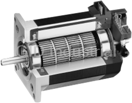
PACIFIC SCIENTIFIC PowerMax II
Description
Pacific Scientific POWERMAX II Series Servo Motors
Part Number
PowerMax II
Price
Request Quote
Manufacturer
PACIFIC SCIENTIFIC
Lead Time
Request Quote
Category
Servo Drive
Datasheet

Extracted Text
599-95 Step Mtrs Sel Gd.out 11/15/00 1:44 PM Page 39 ® POWERMAX II All-in-one molded stator Integral electrical receptacle Neodymium-iron-boron assembly provides high retention force of rotor magnets mating connector—8 flying leads are standard option Exposed laminations aid thermal dissipation Rugged end bell, encapsulated windings and electrical connector utilize high-tech polymer Class B insulation New end bell runs cooler; encoder life is enhanced Many drive shaft modifications available Optional encoders and rear shaft extensions Precision ground rotor OD and honed stator ID for concentric air gap Largest available shaft diameter (0.375") on a NEMA 23 stepper Octagonal shape simplifies withstands high radial and axial automated assembly loads, supports numerous shaft modifications ® • Available Sigmax technology Oversized 30mm bearings adds flux concentrating samarium cobalt stator magnets for highest increase bearing fatigue life (L ) 400% over typical torque and acceleration 10 NEMA Size 23 mounting 22mm bearings ® MODEL NUMBER CODE POWERMAX II motors P 2 1 N R X A - L N N - N S - 0 0 Sequence Number Insert 00 if all parts Type are standard. Factory P=Standard assigned if any parts Winding Type M=Enhanced are custom. A...per assigned letter (n/a half stack) Construction S=Special R=Regular Encoder Option S=Special Size NS=No Feedback Rotor Type 2=NEMA 23 Use encoders below.You must specify L=Standard (2.25"across flats) shaft configuration D (double ended) Termination J=Low inertia X=Receptacle (n/a half stack) Caution: An encoder with line F=8 Flying leads driver output may be S=Special Number of Stacks required for use with some For X (receptacle) designation, H=Half stack Shaft Configuration step motor controls. mating leaded connectors may 1=1 Stack (Diameter & Length) be ordered separately. 2=2 Stacks N=Single M1=Encoder mounting provisions Optional GRN/YEL ground wire D=Double HD=Encoder 500ppr available. See p. 52 S=Special HJ=Encoder 512ppr Mounting SS=Special, call factory N=NEMA S=Special Shaft Modifications N=Smooth F=Flat S=Special The example model number above indicates a standard NEMA 23 frame motor with a one stack rotor. This motor is equipped with a standard NEMA mount, regular construction, receptacle and an A winding. It also has a standard rotor, a smooth single-ended shaft and no encoder or encoder mounting provisions. HOW TO ORDER Review the Motor Model Number Code to assure that all options are designated. Dimensions, connections and phasing diagrams start on page 49. Encoder mounting options are on page 53. 39 www.pacsci.com 599-95 Step Mtrs Sel Gd.out 11/15/00 1:44 PM Page 38 ® POWERMAX II FEATURES BENEFITS Two Year Warranty High quality, dependable operation ® POWERMAX II sets the world New Polymer Encapsulated Stator Exceptional thermal dissipation performance standard for NEMA 23 step motors. At up to 253 oz-in. New Polymer End Bell with Threaded End bell runs cooler, provides greater holding torque, you won’t find a more Inserts flexibility in mounting encoder and brake powerful two inch stepper. options With POWERMAX II you also gain Largest Available Shaft Diameter on a Withstands high radial and axial loads. the cost advantages of design for NEMA 23 Stepper Supports numerous shaft modifications. manufacturability (DFM) and North America’s most advanced step motor Oversized 30mm Bearings Increases bearing fatigue life (L ), extends 10 motor life, reduces downtime manufacturing line. That makes POWERMAX II ® Sigmax Technology Increases available torque economical without sacrificing features - such as long life bearings, Optional Low Inertia Rotor Produces the highest acceleration rate possible high temperature insulation and quality magnet materials. Optional Solid Rotor High low speed torque, fast settling, Plus DFM means we can build superior stiffness and damping POWERMAX II to your specifications, Precision Ground Rotor OD and Honed High quality performance in an economical in the volumes you need, according Stator ID for Concentric Air Gap in an motor design. to your JIT or other delivery Economical Motor Design schedule. Exposed Laminations Aids Thermal Improved heat dissipation extends Dissipation motor life, reduces downtime. Standard Standard POWERMAX II motors High Performance Gearheads Increases torque range in a reliable, come in half, single and two stacks complete package that provide holding torques from 42 to 253 oz-in. Custom POWERMAX II proves that an economical step motor doesn’t have to limit your options. It’s just the opposite, thanks to flexible manufacturing. Whether you require a simple drive shaft flat or an integral lead screw, POWERMAX II motors are made to order. 38 www.pacsci.com 599-95 Step Mtrs Sel Gd.out 11/15/00 1:45 PM Page 44 ® POWERMAX II MOTOR TECHNOLOGY ® Pacific Scientific developed POWERMAX II to be the Does your application require that extra measure of best cost/performance value available in hybrid step performance? Then consider the POWERMAX II M ® motors. Series, featuring the patented Sigmax technology.* That’s why you’ll find so many standard Samarium cobalt magnets in M Series motors POWERMAX II models in the universal NEMA 23 concentrate magnetic flux at desired points between frame size. With POWERMAX II, you can tailor motor the rotor and stator. Sigmax technology optimizes flux torque, acceleration and inertia to every axis of your paths to increase torque production and current design. And you can do this economically too, using utilization over conventional hybrid designs. a single mounting configuration and the driver of your choice. M SERIES ENHANCED HYBRID ® SIGMAX TECHNOLOGY P SERIES STANDARD HYBRID Stator S Stator S S S Rare earth magnet Non-torque N N inserts producing flux Focusing flux Torque producing flux Concentrated torque producing flux Rotor Rotor N N ® Patented Sigmax Typical paths of flux transfer technology* redirects magnetic in an energized conventional flux to inhibit leakage and hybrid step motor. Some flux optimize torque production. leakage occurs in normal operation. ® * Sigmax technology is covered by U.S. patents 4,712,028, 4,713,470, 4,763,034 and 4,827,164. TECHNICAL OVERVIEW Types POWERMAX II M Series . . . . . . . . . . . . . . . . . . . . . . . . . . . . . . . . . . . . Hybrid step motors with rare earth magnets in the stator teeth POWERMAX II P Series . . . . . . . . . . . . . . . . . . . . . . . . . . . . . . . . . . . . Hybrid step motors Rotor construction POWERMAX II M and P Series; with “L” rotor designates . . . . . . . . . . . . . . . . . . . . . . . . . . . . . . . . . . . . Laminated (high speed efficiency) POWERMAX II M and P Series; with “J” rotor designates . . . . . . . . . . . . . . . . . . . . . . . . . . . . . . . . . . . . . Low mass/low inertia (fast start/stop, high acceleration) Windings A, B, C, D, E, F, G . . . . . . . . . . . . . . . . . . . . . . . . . . . . . . . . . . . . . . . . . Standard winding to match any application Phases . . . . . . . . . . . . . . . . . . . . . . . . . . . . . . . . . . . . . . . . . . . . . . . . . . . . . . . . 2 Full steps per revolution . . . . . . . . . . . . . . . . . . . . . . . . . . . . . . . . . . . . . . . . . . . . . 200 Full step angle . . . . . . . . . . . . . . . . . . . . . . . . . . . . . . . . . . . . . . . . . . . . . . . . . . . . . 1.8° Angular accuracy POWERMAX II M and M “J” . . . . . . . . . . . . . . . . . . . . . . . . . . . . . . . . . . ±1.5% of one step, no load, non-cumulative POWERMAX II P and P “J” . . . . . . . . . . . . . . . . . . . . . . . . . . . . . . . . . . ±3% of one step, no load, non-cumulative Operating temperature . . . . . . . . . . . . . . . . . . . . . . . . . . . . . . . . . . . . . . . . . . . . . . . -20 to 40°C Insulation . . . . . . . . . . . . . . . . . . . . . . . . . . . . . . . . . . . . . . . . . . . . . . . . . . . . . . . NEMA Class B, 130°C Insulation resistance . . . . . . . . . . . . . . . . . . . . . . . . . . . . . . . . . . . . . . . . . . . . . . . . 100 Megohms @500V dc and 25°C Shaft load ratings Max. radial load (at center of std. shaft extension) . . . . . . . . . . . . . . . . . 20 lb. Max. axial load (on front shaft extension toward motor) . . . . . . . . . . . . . 13 lb. Bearing life . . . . . . . . . . . . . . . . . . . . . . . . . . . . . . . . . . . . . . . . . . . . . . . . . . . . . . . Since large bearings (30 mm) are used, life is typically about 4 times that of 22 mm or smaller bearings used on other NEMA Size 23 motors. POWERMAX II bearing fatigue life (L ) exceeds 10,000 hours at any rotational 10 speed up to 10,000 full steps/second if operated within the max. radial and axial loads specified above. Encoder options . . . . . . . . . . . . . . . . . . . . . . . . . . . . . . . . . . . . . . . . . . . . . . . . . . . See page 53. 44 www.pacsci.com 599-95 Step Mtrs Sel Gd.out 11/15/00 1:45 PM Page 45 ® POWERMAX II HYBRIDS NEMA 23 FRAME (2.3")—Ratings and Characteristics Review the Model Number Code on page 39 to assure that all options are designated. Dimensions, connections and phasing diagrams are on page 49. In addition to those below, motors with characteristics for specific performance requirements are offered. Contact factory for more details. Connection Holding Torque Phase Rated Inductance Rated Currents are in Current/ Phase Thermal Rotor descending order Motor (2 phases on) Phase Resistance Detent Resistance Inertia 2 Model Number oz-in (Nm) (ohms) (mH) Torque oz-in-S Weight o 2 -3 ±10% (amps DC) ±10% Typical oz-in (Nm) ( C/watt) (kgm x 10 ) lbs (kg) P2HNXXH-LXX-XX-00 • 59 (0.42) 5.2 0.22 0.5 Torque range: P2HNXXH-LXX-XX-00 • 59 (0.42) 2.6 0.90 1.9 42-61 oz-in. P2HNXXH-LXX-XX-00 • 42 (0.29) 3.68 0.44 0.5 .29-.43 Nm STANDARD P2HNXXB-LXX-XX-00 • 59 (0.42) 2.6 0.76 1.9 P2H Series P2HNXXB-LXX-XX-00 • 59 (0.42) 1.3 3.04 7.6 1/2 rotor stack P2HNXXB-LXX-XX-00 • 42 (0.29) 1.84 1.52 1.9 2.5 0.0010 1.0 6.6 (0.018) (0.007) (0.45) P2HNXXC-LXX-XX-00 • 61 (0.43) 2.5 0.84 2.3 P2HNXXC-LXX-XX-00 • 61 (0.43) 1.25 3.36 9.2 P2HNXXC-LXX-XX-00 • 43 (0.30) 1.77 1.68 2.3 P2HNXXF-LXX-XX-00 • 60 (0.42) 1.61 1.92 5.1 P2HNXXF-LXX-XX-00 • 60 (0.42) 0.80 7.68 20.4 P2HNXXF-LXX-XX-00 • 42 (0.30) 1.10 3.84 5.1 All ratings typical and at 25°C unless otherwise noted. Windings at 130°C and motor in still air at 40°C (without heat sink). Operation of these motors above rated current may cause An “X” in the Model Number Code indicates an undefined option. demagnetization. Contact factory. Colored letter indicates winding. See Model Number Code on page 39. Small signal inductance as measured with impedance bridge at 1kHz, 1 amp. See Model Number Code on page 39, optional leaded connectors on page 52 and connection information on page 52. Thermal resistance measured with motor hanging in still air (unmounted). With rated current applied. Windings at 130°C and motor unmounted and in still air at 40°C (without heat sink). 45 www.pacsci.com Parallel Series Unipolar 599-95 Step Mtrs Sel Gd.out 11/15/00 1:45 PM Page 46 ® POWERMAX II HYBRIDS NEMA 23 FRAME (2.3")—Ratings and Characteristics (Con’t) Review the Model Number Code, page 39, to assure that all options are designated. Dimensions, connections and phasing diagrams are on page 49. In addition to those below, motors with characteristics for specific performance requirements are offered. Contact factory for more details. Connection Holding Torque Phase Rated Inductance Rated Currents are in Current/ Phase Thermal Rotor descending order Motor (2 phases on) Phase Resistance Detent Resistance Inertia 2 Model Number oz-in (Nm) (ohms) (mH) Torque oz-in-S Weight o 2 -3 ±10% (amps DC) ±10% Typical oz-in (Nm) ( C/watt) (kgm x 10 ) lbs (kg) M21NXXA-LXX-XX-00 • 142 (1.00) 5.6 0.23 0.7 Torque range: M21NXXA-LXX-XX-00 • 142 (1.00) 2.8 0.92 2.8 95-144 oz-in. M21NXXA-LXX-XX-00 • 100 (0.71) 4.0 0.46 0.7 .67-1.02 Nm ® SIGMAX M21NXXB-LXX-XX-00 • 137 (0.97) 4.6 0.32 1.0 M21 Series M21NXXB-LXX-XX-00 • 137 (0.97) 2.3 1.28 4.0 1 rotor stack M21NXXB-LXX-XX-00 • 97 (0.68) 3.3 0.64 1.0 9.4 0.0017 1.5 5.5 (0.066) (0.012) (0.68) M21NXXC-LXX-XX-00 • 144 (1.02) 3.5 0.53 2.0 M21NXXC-LXX-XX-00 • 144 (1.02) 1.75 2.12 8.0 M21NXXC-LXX-XX-00 • 102 (0.72) 2.5 1.06 2.0 M21NXXD-LXX-XX-00 • 135 (0.95) 1.51 2.61 8.7 M21NXXD-LXX-XX-00 • 135 (0.95) 0.76 10.4 34.8 M21NXXD-LXX-XX-00 • 95 (0.67) 1.07 5.22 8.7 P21NXXA-LXX-XX-00 • 114 (0.81) 5.6 0.23 0.8 Torque range: 77-116 oz-in. P21NXXA-LXX-XX-00 • 114 (0.81) 2.8 0.92 3.2 .54-.82 Nm P21NXXA-LXX-XX-00 • 81 (0.57) 4.0 0.46 0.8 STANDARD P21NXXB-LXX-XX-00 • 111 (0.79) 4.6 0.32 1.1 P21 Series P21NXXB-LXX-XX-00 • 111 (0.79) 2.3 1.28 4.4 1 rotor stack P21NXXB-LXX-XX-00 • 79 (0.55) 3.3 0.64 1.1 4 0.0017 1.5 5.5 (0.028) (0.012) (0.68) P21NXXC-LXX-XX-00 • 116 (0.82) 3.5 0.53 2.3 P21NXXC-LXX-XX-00 • 116 (0.82) 1.75 2.12 9.2 P21NXXC-LXX-XX-00 • 82 (0.58) 2.5 1.06 2.3 P21NXXD-LXX-XX-00 • 109 (0.77) 1.51 2.61 10.3 P21NXXD-LXX-XX-00 • 109 (0.77) 0.76 10.4 41.2 P21NXXD-LXX-XX-00 • 77 (0.54) 1.07 5.22 10.3 All ratings typical and at 25°C unless otherwise noted. Windings at 130°C and motor in still air at 40°C (without heat sink). Operation of these motors above rated current may cause An “X” in the Model Number Code indicates an undefined demagnetization. Contact factory. option. Colored letter indicates winding. See Model Number Code on page 39. Small signal inductance as measured with impedance bridge at 1kHz, 1 amp. See Model Number Code on page 39, optional leaded connectors on page 52 and connection information on Thermal resistance measured with motor hanging in still air page 52. (unmounted). With rated current applied. Windings at 130°C and motor unmounted and in still air at 40°C (without heat sink). 46 www.pacsci.com Parallel Series Unipolar 599-95 Step Mtrs Sel Gd.out 11/15/00 1:45 PM Page 47 ® POWERMAX II HYBRIDS NEMA 23 FRAME (2.3")—Ratings and Characteristics (Con’t.) Review the Model Number Code, page 39, to assure that all options are designated. Dimensions, connections and phasing diagrams are on page 49. In addition to those below, motors with characteristics for specific performance requirements are offered. Contact factory for more details. Connection Holding Torque Phase Rated Inductance Rated Currents are in Current/ Phase Thermal Rotor descending order Motor (2 phases on) Phase Resistance Detent Resistance Inertia 2 Model Number oz-in (Nm) (ohms) (mH) Torque oz-in-S Weight o 2 -3 ±10% (amps DC) ±10% Typical oz-in (Nm) ( C/watt) (kgm x 10 ) lbs (kg) M22NXXA-LXX-XX-00 • 230 (1.62) 6.5 0.21 0.7 Torque range: M22NXXA-LXX-XX-00 • 230 (1.62) 3.3 0.84 2.8 161-253 oz-in. M22NXXA-LXX-XX-00 • 163 (1.15) 4.6 0.42 0.7 1.13-1.79 Nm ® SIGMAX M22NXXB-LXX-XX-00 • 253 (1.79) 4.6 0.38 1.7 M22 Series M22NXXB-LXX-XX-00 • 253 (1.79) 2.3 1.52 6.8 2 rotor stack M22NXXB-LXX-XX-00 • 179 (1.26) 3.3 0.76 1.7 M22NXXC-LXX-XX-00 • 238 (1.68) 3.1 0.78 3.1 17 0.0036 2.5 M22NXXC-LXX-XX-00 • 238 (1.68) 1.55 3.12 12.4 4.5 (0.12) (0.025) (1.13) M22NXXC-LXX-XX-00 • 168 (1.19) 2.2 1.56 3.1 M22NXXD-LXX-XX-00 • 238 (1.68) 2.5 1.22 5.0 M22NXXD-LXX-XX-00 • 238 (1.68) 1.25 4.88 20.0 M22NXXD-LXX-XX-00 • 168 (1.19) 1.77 2.44 5.0 M22NXXE-LXX-XX-00 • 227 (1.60) 1.64 2.71 10.1 M22NXXE-LXX-XX-00 • 227 (1.60) 0.82 10.8 40.4 M22NXXE-LXX-XX-00 • 161 (1.13) 1.16 5.42 10.1 Torque range: P22NXXA-LXX-XX-00 • 197 (1.39) 6.5 0.21 0.8 138-214 oz-in. P22NXXA-LXX-XX-00 • 197 (1.39) 3.3 0.84 3.2 .97-1.51 Nm P22NXXA-LXX-XX-00 • 139 (0.98) 4.6 0.42 0.8 STANDARD P22NXXB-LXX-XX-00 • 214 (1.51) 4.6 0.38 2.1 P22 Series P22NXXB-LXX-XX-00 • 214 (1.51) 2.3 1.52 8.4 2 rotor stack P22NXXB-LXX-XX-00 • 151 (1.07) 3.3 0.76 2.1 P22NXXC-LXX-XX-00 • 203 (1.43) 3.1 0.78 3.9 7 0.0036 2.5 4.5 P22NXXC-LXX-XX-00 • 203 (1.43) 1.55 3.12 15.6 (0.049) (0.025) (1.13) P22NXXC-LXX-XX-00 • 144 (1.01) 2.2 1.56 3.9 P22NXXD-LXX-XX-00 • 203 (1.43) 2.5 1.22 6.2 P22NXXD-LXX-XX-00 • 203 (1.43) 1.25 4.88 24.8 P22NXXD-LXX-XX-00 • 144 (1.01) 1.77 2.44 6.2 P22NXXE-LXX-XX-00 • 195 (1.38) 1.64 2.7 12.6 P22NXXE-LXX-XX-00 • 195 (1.38) 0.82 10.8 50.4 P22NXXE-LXX-XX-00 • 138 (0.97) 1.16 5.4 12.6 All ratings typical and at 25°C unless otherwise noted. Windings at 130°C and motor in still air at 40°C (without heat sink). Operation of these motors above rated current may cause An “X” in the Model Number Code indicates an undefined option. demagnetization. Contact factory. Colored letter indicates winding. See Model Number Code on page 39. Small signal inductance as measured with impedance bridge at See Model Number Code on page 39 optional leaded connectors on 1kHz, 1 amp. page 52 and connection information on page 52. Thermal resistance measured with motor hanging in still air With rated current applied. Windings at 130°C and motor unmounted (unmounted). and in still air at 40°C (without heat sink). 47 www.pacsci.com Parallel Series Unipolar 599-95 Step Mtrs Sel Gd.out 11/15/00 1:45 PM Page 48 ® POWERMAX II HYBRIDS WITH LOW INERTIA ROTORS ® ROTOR INERTIA CHARACTERISTICS . . . POWERMAX II motors ® Single and double stack POWERMAX II motors are ACCELERATION COMPARISON available with both standard and low inertia rotors. Choose low inertia to produce the highest Theoretical acceleration rates possible. Inertia Normalized 2 -3 Model Rotor Type oz-in-S x 10 / Acceleration 2 -3 kgm x 10 comparison P21NRXX-L Standard 1.68/0.010 1 P21NRXX-J Low inertia 1.30/0.008 1.27 M21NRXX-L Standard 1.68/0.010 1.23 M21NRXX-J Low inertia 1.30/0.008 1.59 P22NRXX-L Standard 3.57/0.022 1 P22NRXX-J Low inertia 2.59/0.016 1.30 M22NRXX-L Standard 3.57/0.022 1.18 M22NRXX-J Low inertia 2.59/0.016 1.63 Low inertia rotors not offered for half stack models Comparative values for normalized acceleration of unloaded motors. Base value is standard Low inertia rotor Standard rotor hybrid motor with standard rotor, indicated for single and double stack lengths. Actual acceleration capability depends on load, velocity profile and driver power. Comparisons made with 90°C temperature rise using bipolar driver. NEMA 23 FRAME (2.3")—Ratings and Characteristics Review the Model Number Code, page 39, to assure that all options are designated. Dimensions, connections and phasing diagrams start on page 49. In addition to those below, all 1 and 2 stack "L" construction windings, page 59, and custom windings for specific performance requirements are available with low inertia rotors. Contact factory for more details. Connection Holding Torque Phase Rated Inductance Current/ Phase Thermal Rotor Motor (2 phases on) Phase Resistance Detent Resistance Inertia 2 Model Number oz-in (Nm) (ohms) (mH) Torque oz-in-S Weight o 2 -3 ±10% (amps DC) ±10% Typical oz-in (Nm) ( C/watt) (kgm x 10 ) lbs (kg) Torque range: 99-140 oz-in. M21NXXA-JXX-XX-00 • 140 (0.99) 5.6 0.23 0.7 .70-.99 Nm 9.4 M21NXXA-JXX-XX-00 • 140 (0.99) 2.8 0.92 2.8 ® SIGMAX (0.066) M21NXXA-JXX-XX-00 • 99 (0.70) 4.0 0.46 0.7 M21 Series 1 rotor stack 0.0013 1.5 5.5 (0.009) (0.68) Torque range: 79-111 oz-in. P21NXXA-JXX-XX-00 • 111 (0.78) 5.6 0.23 0.9 .55-.78 Nm 4 P21NXXA-JXX-XX-00 • 111 (0.78) 2.8 0.92 3.6 (0.028) STANDARD P21NXXA-JXX-XX-00 • 79 (0.55) 4.0 0.46 0.9 P21Series 1 rotor stack Torque range: 178-252 oz-in. M22NXXB-JXX-XX-00 • 252 (1.78) 4.6 0.38 1.5 1.26-1.78 Nm 17 M22NXXB-JXX-XX-00 • 252 (1.78) 2.3 1.52 6.0 ® (0.12) SIGMAX M22NXXB-JXX-XX-00 • 178 (1.26) 3.3 0.76 1.5 M22 Series 2 rotor stack 0.0026 2.5 4.5 (0.018) (1.13) Torque range: 142-201 oz-in. P22NXXB-JXX-XX-00 • 201 (1.42) 4.6 0.38 1.8 1.00-1.42 Nm 7 P22NXXB-JXX-XX-00 • 201 (1.42) 2.3 1.52 7.2 STANDARD (0.049) P22NXXB-JXX-XX-00 • 142 (1.00) 3.3 0.76 1.8 P22 Series 2 rotor stack All ratings typical and at 25°C unless otherwise noted. Windings at 130°C and motor in still air at 40°C (without heat sink). Operation of these motors above rated current may cause An “X” in the Model Number Code indicates an undefined option. Colored demagnetization. Contact factory letter indicates winding. See Model Number Code on page 39. Small signal inductance as measured with impedance bridge at See Model Number Code on page 39, optional leaded connectors on page 1kHz, 1 amp. 52 and connection information on page 52. Thermal resistance measured with motor hanging in still air With rated current applied. Windings at 130°C and motor unmounted and in (unmounted). still air at 40°C (without heat sink). 48 www.pacsci.com Parallel Series Unipolar Double Stack Single Stack 599-95 Step Mtrs Sel Gd.out 11/15/00 1:45 PM Page 49 ® in. DIMENSIONS. . .(POWERMAX II HYBRIDS) (metric dim. for ref. only) mm 87654321 ( 2.25) (57,10) .48 MAX. (12,19) WITH MATING (2X 1.85) 4X Ş .200 (5,080) THRU CONNECTOR PLUGGED IN (46,99) EQUALLY SPACED ON A Ş 2.625 (66,670) B.C. .18 MAX. (4,57) .99 MAX MOTOR ONLY 25,20 (2X 45°) 6,35 ± 0,000 +.0000 -0,013 .2500 –.0005 Ş Ş .2500 ± Ş 0,000 6,35 +0,000 -.0005 –0,013 .002 .002 0,051 (.20) -A- 5,08 (2.44) .055 (62,00) 1,400 38,1 ± 0,05 Ş 1.500 ± .002 .81 .75 ± .04 L MAX. .003 A 20,60 19,1 ± 1,02 0,077 .003 A 0,077 STANDARD SHAFT OPTIONS ENCODER OPTION Motor L Model Max. 1. Shaft modifications also available. See page 39. See page 53 for encoder/mounting specifications. 2. Optional flat available on front shaft as shown. 1.60 P2H .50 40,7 .219 USABLE 12,7 FLAT 2.06 5,56 AGILENT P or M21 TECHNOLOGIES 52,3 ENCODER 3.10 P or M22 78,7 Optional rear shaft extension available as shown. Same diameter as front shaft extension. (1.812) ş .72 (46,02) 18,29 CONNECTION INFORMATION . . .Terminations and phase sequencing NOTE: Phase sequencing direction of rotation as viewed from mounting end of motor. 6 8 LEAD 2 5 1 DRIVER CONNECTION DRIVER CONNECTION 8 47 3 STEP AB C D STEP AA B B PHASE B 1 GND O GND O 1 CCW CCW A O GND GND O 2 2 A +V 3 O GND O GND 3 A CW CW B GND O O GND 4 4 GND O 1 O GND 1 B B C +V D Unipolar full step Bipolar full step 4-Lead connection 6-Lead connection (Bipolar) (Unipolar) Notes: 0 = off or open + = positive current flow - = negative current flow GND = ground 49 www.pacsci.com PHASE A 599-95 Step Mtrs Sel Gd.out 11/15/00 1:45 PM Page 50 ® POWERMAX II Flying Lead Motor Connection Informations CONNECTION LEAD COLOR DRIVER CONNECTION 4-LEAD BIPOLAR BLK A BIPOLAR ORG A SERIES RED B YEL B WHT/BLK & WHT/ORG — WHT/RED & WHT/YE — WHT/RED & WHT/YEL — 4-LEAD BIPOLAR BLK & WHT/ORG A BIPOLAR ORG & WHT/BLK A PARALLEL RED & WHT/YEL B YEL & WHT/RED B 6-LEAD UNIPOLAR BLK A UNIPOLAR ORG B RED C YEL D WHT/BLK & WHT/ORG +V WHT/RED & WHT/YEL +V CONNECTION INFORMATION . . .Terminations and phase sequencing NOTE: Phase sequencing direction of rotation as viewed from mounting end of motor. DRIVER CONNECTION STEP AB C D A Blk 1 GND O GND O CCW Wht/Blk +V O Wht/Org 2 O GND GND Org 3 O GND O GND B CW Red Wht/ Wht/ Yel GND 4 GND O O Red Yel Blk O 1 GND O GND Wht/Blk Wht/Org Unipolar full step 6-Lead connection (Unipolar) Org Red Wht/ Wht/ Yel Red Yel DRIVER CONNECTION PHASE B A A 8 lead motor STEP AA B B Blk Blk (reference only Wht/Blk Wht/Blk 1 Wht/Org CCW Wht/Org Org Org 2 B A 3 Red Red Wht/ Wht/ Yel Yel Red Yel CW Wht/ Wht/ Red Yel 4 B B 1 SERIES PARALLEL Bipolar full step 4-Lead motor (Bipolar) Notes: off or open 0 = positive current flow + = negative current flow - = ground GND = 50 www.pacsci.com PHASE A 599-95 Step Mtrs Sel Gd.out 11/15/00 1:45 PM Page 51 ® POWERMAX II Flying Lead Motor (57,10) ( 2.25) (.25) (2X 1.85) (6,35) (46,99) 12.0 MIN (304,8) 4X Ş .200 (5,080) THRU EQUALLY SPACED ON A Ş 2.625 (66,670) B.C. (26,92) 1 (1.06) (2X 45°) 6,35 + 0,000 +.0000 - 0,013 .2500 –.0005 Ş Ş .2500 + 0,000 +0,000 6,35 –0,013 - .0005 .002 .002 (.20) 0,051 5,08 -A- (2.44) .055 (62,00) 1,400 38,1 ± 0,05 .81 Ş 1.500 ± .002 .75 ± .04 L MAX. 20,60 .003 A 19,10 ± 1,02 0,076 .003 A 0,076 Motor L Model Max. 1.60 P2H 40,7 2.06 P or M21 52,4 3.10 P or M22 78,8 NOTES: Flexible rubber boot may be bent as shown. Normal height 1.0 inch (25,4) 51 www.pacsci.com 599-95 Step Mtrs Sel Gd.out 11/15/00 1:45 PM Page 52 ® POWERMAX II CONNECTION INFORMATION . . . . . . Optional leaded connectors Four different leaded connectors are available from Pacific Scientific. Order the “GW” part number as a separate item. Connector/Leadwire Part Phase Assembly Driver Number Connection Pin No. Lead Colors Connection bipolar 6 Black A series 1 Orange A 8 Red B 3 Yellow B 2 & 5 Wht/Blk & Wht/Org none 4 & 7 Wht/Red & Wht/Yel none bipolar 6 & 5 Blk & Wht/Org A GW0000F parallel 1 & 2 Org & Wht/Blk A (8 Lead) 8 & 7 Red & Wht/Yel B 3 & 4 Yel & Wht/Red B unipolar 6 Black A 1 Orange B 8 Red C 3 Yellow D 2 & 5 Wht/Blk & Wht/Org + V 4 & 7 Wht/Red & Wht/Yel + V unipolar 6 Black A 1 Orange B GW0000E 8 Red C (6 Lead) 3 Yellow D 2 & 5 Wht/Blk & Org + V 4 & 7 Wht/Red & Yel + V bipolar 6 & 5 Black A GW0000H parallel 1 & 2 Orange A (4 Lead) 8 & 7 Red B 3 & 4 Yellow B bipolar 6 Black A GW0000L series 1 Orange A (4 Lead) 8 Red B 3 Yellow B Optional Ground Wire Typical leaded connector (4-lead shown) +.00 .25 .06 #22 AWG, PVC LEADS +2.0 12.0 0.0 NOTES: . . . Optional mating connector only GROUND LABEL PLACED IN A separate mating connector housing and strain relief cover FRONT OF GROUND SCREW. are available from Pacific Scientific or AMP. The GREEN/YELLOW SAFETY EARTH CONDUCTOR (18AWG). user attaches leads to the connector. PACIFIC See page 39 for ordering information. ITEM SCIENTIFIC AMP STANDARD HOUSING GP00012 641653-8 STANDARD COVER GP00013 643077-8 52 www.pacsci.com 599-95 Step Mtrs Sel Gd.out 11/15/00 1:45 PM Page 53 ENCODER OPTIONS NEMA 23 ENCODER OPTION The standard encoder offered on the NEMA 23 motor is the Agilent Technologies HEDS 5600 series. NON-LINE DRIVER ENCODER 2.05 Ş 1.812 ENCODER ENCODER OUTPUT FOR CW DIRECTION OF ROTATION WHEN VIEWED FROM MOTOR DRIVE SHAFT END. (COMPLEMENTS NOT SHOWN) MIN. EDGE SEPARATION 45°. INDEX GATED TO A AND B. CHANNEL A 1.03 MAX. CHANNEL B PIN 1235 4 INDEX (Z) .44 Ş .108 18.0 MIN. 5X LEADS 1 1.18 PIN COLOR FUNCTION 1 BLACK GROUND 2 BLUE Z 3 WHITE A 4 RED +5V 5 BROWN B PARAMETERS NON-LINE DRIVER TYPE INCREMENTAL ENCODER OPTION HD HJ PULSES PER REVOLUTION 500 512 SUPPLY VOLTAGE +5V ± 10% @ 85 mA MAX. OUTPUT FORMAT DUAL CHANNEL QUADRATURE AND INDEX OUTPUT TYPE SQUARE WAVE TTL COMPATIBLE FREQUENCY RESPONSE: DATA 100 kHz INDEX 100 kHz -7 2 ROTOR INERTIA 5 x 10 lb-in-S WEIGHT 0.08 lb. ENCODER MOUNTING PROVISION ONLY = M1 FOR AGILENT TECHNOLOGIES HEDS 5600 SERIES OR SIMILAR. 2X 2-56 UNC-2B .170 MIN. DEEP EQUALLY SPACED ON A Ş 1.812 B.C. (Ş 1.1812) +.0000 SHAFT DIA. .2500 - .0005 SHAFT LENGTH .75 ± .06 NOTES: Leads are terminated with Agilent Technologies HEDS-8903 connector. TYPICAL @ 25° C 53 www.pacsci.com
Frequently asked questions
How does Industrial Trading differ from its competitors?

Is there a warranty for the PowerMax II?
Which carrier will Industrial Trading use to ship my parts?
Can I buy parts from Industrial Trading if I am outside the USA?
Which payment methods does Industrial Trading accept?


What they say about us
FANTASTIC RESOURCE
One of our top priorities is maintaining our business with precision, and we are constantly looking for affiliates that can help us achieve our goal. With the aid of GID Industrial, our obsolete product management has never been more efficient. They have been a great resource to our company, and have quickly become a go-to supplier on our list!
Bucher Emhart Glass
EXCELLENT SERVICE
With our strict fundamentals and high expectations, we were surprised when we came across GID Industrial and their competitive pricing. When we approached them with our issue, they were incredibly confident in being able to provide us with a seamless solution at the best price for us. GID Industrial quickly understood our needs and provided us with excellent service, as well as fully tested product to ensure what we received would be the right fit for our company.
Fuji
HARD TO FIND A BETTER PROVIDER
Our company provides services to aid in the manufacture of technological products, such as semiconductors and flat panel displays, and often searching for distributors of obsolete product we require can waste time and money. Finding GID Industrial proved to be a great asset to our company, with cost effective solutions and superior knowledge on all of their materials, it’d be hard to find a better provider of obsolete or hard to find products.
Applied Materials
CONSISTENTLY DELIVERS QUALITY SOLUTIONS
Over the years, the equipment used in our company becomes discontinued, but they’re still of great use to us and our customers. Once these products are no longer available through the manufacturer, finding a reliable, quick supplier is a necessity, and luckily for us, GID Industrial has provided the most trustworthy, quality solutions to our obsolete component needs.
Nidec Vamco
TERRIFIC RESOURCE
This company has been a terrific help to us (I work for Trican Well Service) in sourcing the Micron Ram Memory we needed for our Siemens computers. Great service! And great pricing! I know when the product is shipping and when it will arrive, all the way through the ordering process.
Trican Well Service
GO TO SOURCE
When I can't find an obsolete part, I first call GID and they'll come up with my parts every time. Great customer service and follow up as well. Scott emails me from time to time to touch base and see if we're having trouble finding something.....which is often with our 25 yr old equipment.
ConAgra Foods