

 Manufacturers
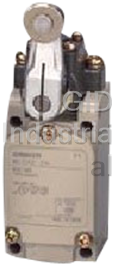
OMRON WLCA2-2
Description
Omron WLCA2-2 Limit Switch
Part Number
WLCA2-2
Price
Request Quote
Manufacturer
OMRON
Lead Time
Request Quote
Category
Limit Switches
Datasheet

Extracted Text
Two-circuit Limit Switch/Long-life Two-circuit Limit Switch WL/WLM CSM_WL_WLM_DS_E_13_1 Wide Range of Two-circuit Switches; Select One for the Operating Environment/Application • A wide selection of models are available, including the overtravel models with greater OT, indicator-equipped models for checking operation, low-temperature models, heat-resistant models, and corrosion-proof models. • Microload models are added to the product lineup. • Approved standards: EC/IEC, UL, CSA, CCC (Chinese standard). Contact your OMRON representative for information on approved models. Be sure to read Safety Precautions on page 39 to 42 and Safety Precautions for All Limit Switches. Features Standard Models Features Common to All Models Many Variations in Standard Limit Switches DPDB Operation A Wide Range of Models The double-pole, double-break structure ensures circuit braking. The WL Series provides a complete range of Limit Switches with a 1 4 long history of meeting user needs. Select environment-resistant 2 3 specifications, actuators for essentially any workpiece, operating Za (NO)4 3(NO) sensitivity matched to the workpiece, operation indicators to aid operation and maintenance, and various wiring specifications. (NC)1 2(NC) Load Load Environment-resistant Models Select from Six Types of Environment Resistance Degree of Protection; IP67 The series includes Airtight Switches, Hermetic Switches, Heat- O-rings, cover seals, and other measures provide a water-proof, drip- resistant Switches, Low-temperature Switches, Corrosion-proof proof structure (IP67). switches, and Weather-proof Switches. Select the one required by the Approved Standards to Aid Export Machines onsite environment. Various WL/WLM switches are approved by UL, CSA, TÜV, EN/IEC, and CCC making them ideal for export machines. Spatter-prevention Models High-precision Models Available in All Switch Types; Excellent Performance on Arc Welding Lines or Sites with Spattering Cutting Powder Ideal for Position Control Ideal for Welding Sites High-precision models achieve a very small movement to operation Stainless steel and resins that resist adhesion of spatters are used to (approx. 5°) and a repeat accuracy that is twice that of basic models. prevent troubles caused by zinc powder generated during welding. Operation Indicators for Easier Daily Inspections* Long-life Models Confirm operation with a neon lamp or LED for Mechanical Endurance of 30 Million Operations easier startup confirmations and maintenance. Long-life Models for High-frequency Applications * Operation indicators are provided on Indicator- Operation equipped switches, Spatter-prevention Basic Long life has been achieved by increasing the resistance to friction indicator Switches, and Long-life Basic Switches. and creating better sliding properties in the head mechanism. Greater visibility is provided when setting with a fluorescent display for setting Models with Connectors to Reduce Wiring the stroke. Reduce wiring with one-touch connection. Models with direct-wired and prewired connectors that make Switch replacement easier are also available. 1 WL/WLM Product Configuration Selection by Purpose ●Standard-load Switches Selection Points WL@ Effective for switching loads of 0.1 A, 125 VAC/30 ●Microload VDC. Switches WL01@ ❍General-purpose Standard Switches ●Basic Switches Selection Points WLC@ WLH@ Effective if the overall ❍High-sensitivity ●Overtravel Switches movement is 80° or 90° Switches when dog angle or WLG@ deflection is absorbed. ❍90° Operation Switches WL@-2 WL@-2N ●High-precision Selection Points Switches Provide twice the repeat accuracy as Basic Switches. WLGCA2 Effective for positioning in machine tools. ●Protective Selection Points WLCA32-@ Effective for protecting the operating status. General- ●Indicator-equipped Switches: Neon lamps purpose Operation indicators WL@-@LE ●Indicator-equipped Switches: Light emitting diodes (LED) Selection Points WL@-@LD · Effective for confirming workpieces passing by on a conveyor or for confirming operation in dark locations. · For standard models, add -LE or -LD. (Operation indicators cannot be used with some environment-resistant ●Direct-wired Switches Sensor I/O connectors WL@-@LDK@ ●Pre-wired Switches Selection Points WL@-@LD-M1@ Effective for reducing wiring work, WL@-@LD-AGJ@/-DGJ@ WL Series making maintenance easier, and WL@-@LD-DK1EJ@ preventing wiring mistakes. ●Airtight Switches WL@-55 ●Hermetic Switches WL@-139 WL@-140 WL@-141 WL@-145 WL@-RP40 Environment-resistant WL@-RP60 ●Heat-resistant Switches Selection Points WL@-TH Enable selection according to the ●Low-temperature Switches operating environment: water, oil, WL@-TC chemicals, high/low temperatures, etc. ●Corrosion-proof Switches WL@-RP ●Weather-proof Switches WL@-P1 ●Basic Switches WLCA2-@S ●Microload Switches Spatter-prevention WL01@-@S ❍General-purpose Switches ●Overtravel Switches WLH2-@S Selection Points ❍High-sensitivity Switches ●High-precision Switches Effective for welding sites or spattering WLG2-@S WLGCA2-@S cutting powder. ●Basic Switches WLMCA2@ ❍General-purpose Switches ●Overtravel Switches WLM Series Long-life WLMH2@ ❍High-sensitivity Switches ●High-precision Switches Selection Points WLMG2@ WLMGCA2@ With high mechanical durability of 30 million operations, effective for high-frequency operation. 2 WL/WLM Tables of Models General-purpose Switches Spatter-prevention Switches Long-life Switches Heads (Roller levers only) General Spatter Features Head specifications Long-life purpose prevention Type One-side Head Model Total travel (TT) Model Model operation mounting With a Roller Lever 45° 45° Possible *1 (Except for Any of Basic WLC@ WLCA2-@SWLMCA2@ long-life 4 directions models.) Overtravel is large, making 80° 80° General- setting the dog easier. Not possible Any of purpose WLH@ WLH2-@SWLH2@ Mounting is compatible with *2 4 directions Overtravel WLH2. Operation is highly sensitive 80° 80° with only 10° pretravel. Overtravel is large, making High-sensitivity Not possible Any of WLG@ WLG2-@SWLMG2@ setting the dog easier. Overtravel *2 4 directions Mounting is compatible with WLG2. Overtravel is large, making Not possible Any of WL@-2 90° 90° setting the dog easier. *2 4 directions Overtravel, Mounting is compatible —— 90° operation Either of with WLCA2-2. WL@-2N Possible *1 2 directions Repeat accuracy is twice that 45° 45° basic models. Any of High-precision WLGCA2 Operation is highly sensitive Possible *1 WLGCA2-@S WLMGCA2@ 4 directions with only 5° pretravel. Ideal for positioning, e.g., When the dog throws the le- ver, the output is reversed 90° and the reversed output is Any of Maintained WLCA32-@ — —— held even after the dog 4 directions passed. The original status is returned to only after the dog passed. *1. One-side operation means that three operational directions can be selected electrically, according to the change in direction of the operating plunger. The operating plunger is set for operation on both sides before delivery. *2. Those models for which one-side operation is impossible can only operate on both sides. Connectors and Conduits General-purpose Spatter-prevention Long-life Wiring type Connector/conduit specifications Model Model Model Direct-wired connector WL@-@LDK@ SC-2F/-4F Connector built-in — WLM@-LDK@ WL@-@LD-M1@ XS2H-series Pre-wired Connector built- WL@-@S-M1@J-1 WLM@-LD-M1J Pre-wired connector WL@-@LD-@GJ@ in WL@-@S-DGJS03 WLM@-LD-@GJ@ WL@-@LD-DK1EJ@ WL@-@ G1/2 with no ground terminal WLM@-LD WL@-@G1@ G1/2 with ground terminal — Conduit (screw terminal) WL@-@G@ Pg13.5 with ground terminal — — WL@-@Y@ M20 with ground terminal — WL@-@TS@ 1/2 14NPT with ground terminal — 3 WL/WLM Environment-resistant Switches Item Environment-resistant Type Model Application Environment-resistant construction Applicable models All models except the low- temperature and heat-re- Uses the W-10FB3-55 Airtight Built-in Switch. sistant models Airtight seal WL@-55 Note: Use the SC Connector for the conduit opening. Note: Models can be produced using standard actuators. All models except the low- WL@-139 For uses in locations sub- temperature and heat-re- ject to cutting oil or water WL@-140 sistant models Note: Models can be produced Hermetic seal Refer to page 25 for information on the environ- WL@-141 using standard (Molded terminals/ ment-resistant construction of Switches with Her- actuators. Only the WL@-145 Anti-coolant) metic Seals. WLCA2, WLGCA2, or WL@-RP40 WLH2 can be produced for the WL@-141 and WL@-RP60 WL@-145. Can be used at a tempera- All models except airtight ture of –40°C (operating Uses a general-purpose built-in switch. seal, hermetic seal, heat- Low-temperature * WL@-TC temperature range: –40 to Silicone rubber is used for rubber parts such as resistant, corrosion-proof, 40°C), but cannot with- the O-ring, gasket, etc. and indicator-equipped stand icing. models All models except airtight seal, hermetic seal, heat- Can be used in tempera-Uses a special built-in switch made from heat- resistant, corrosion-proof, tures of 120°C (operating resistant resin. Heat-resistant * WL@-TH and indicator-equipped, ny- temperature range: 5 to Silicone rubber is used for rubber parts such as lon roller (WLCA2-26N), 120°C). the O-ring, gasket etc. seal roller models, and res- in rod (WLNJ-2) models Diecast parts, such as the switch box, are made of corrosion-proof aluminum. Rubber sealing parts are made of fluorine All models except overtrav- rubber which aids in resisting oil, chemicals and el (90° operation), fork le- For use in locations sub- adverse weather conditions. ver lock (WLCA32-41 to - Corrosion-proof WL@-RP ject to corrosive gases and Exposed nuts and screws (except the actuator 43), low-temperature, heat- chemicals. section) are made of stainless steel. resistant, and indicator- Moving and rotary parts such as rollers are equipped models made of sintered stainless steel or stainless steel. The Head, box, and cover are yellow. Rubber parts are made from silicone rubber, Only basic (WLCA2/CA12/ which has a high-tolerance to deterioration over CL), general-purpose over- time and changes in temperature. travel (WLH2/H12/HL) and For use in parking lots and Weather-proof * WL@-P1Rollers are made of stainless steel to improve high-sensitivity overtravel other outdoor locations. corrosion resistance. (WLG2/G12/GL) models Exposed nuts and screws are made of stainless (excluding heat-resistant steel. models). * Weather Resistance, Cold Resistance, and Heat Resistance Silicon rubber is used to increase resistance to weather, cold, and heat. Silicon rubber, however, can generate silicon gas. (This can occur at room temperature, but the amount of silicon gas generated increases at higher temperatures.) Silicon gas will react as a result of arc energy and form silicon oxide (SiO2). If silicon oxide accumulates on the contacts, contact interference can occur and can interfere with the device. Before using a Switch, test it under actual application conditions (including the environment and operating frequency) to confirm that no problems will occur in actual. 4 WL/WLM Selection Guide With the WL Series, OMRON will combine the switch, Actuator, and wiring method required to build the ideal switch for your application. The WL Series consists of four basic types: General-purpose, En- vironment-resistant, Spatter-prevention, and Long-life Switches. WLCA2 Switches can be used for the most common applications. According to Operating Environment Environment Key specifications Models −10°C +80°C WL@ General-purpose Normal Switches WLM@ Long-life Switches Water-resistant to IP67. +5°C +120°C WL@-TH Heat-resistant High-temperature Switches *1 To increase heat resistance, the rubber material (silicon rubber) and the material of the built-in switch have been changed. −40°C +40°C WL@-TC Low-temperature Low-temperature Switches *1 To increase resistance to cold, silicon rubber and other measures are used. Rubber parts are made from silicone rubber, which has a WL@-P1 Weather-proof high-tolerance to deterioration over time and changes in temperature. Outdoors Switches *1 Rollers are made of stainless steel to improve corrosion resistance. Exposed nuts and screws are made of stainless steel. Corrosion-proof aluminum diecast has been used for the housing, fluorine rubber has been used for rubber parts, and WL@-RP Corrosion-proof Chemicals and oil stainless steel has been used for screws and nuts (except for Switches *1 actuator) to increase resistance to oils, chemicals, and weather. Water drops and mist Uses an airtight built-in switch. WL@-55 Airtight Switches *1 Cables attached. Uses a general-purpose built-in switch. WL@-139 The case cover and conduit opening are molded from epoxy Hermetic, Molded-terminal resin to increase the seal. The cover cannot be removed. Switches *1, *2 Cables attached. Uses an airtight built-in switch. WL@-RP40 The case cover and box interior are molded from epoxy resin to Constant water Hermetic, Molded-terminal increase the seal. The cover cannot be removed. drops and mist Switches *1, *2 The SC connector can be removed, so it is possible to use flexible conduits for the cable. Cables attached. Uses an airtight built-in switch. WL@-140 The cover screws, case cover, box interior, and conduit opening Hermetic, Molded-terminal are molded from epoxy resin to increase the seal. Switches *1, *2 (The cover cannot be removed.) Cables attached. Uses an airtight built-in switch. The cover screws, case cover, box interior, conduit opening, box head, and head screws are molded from epoxy resin to increase WL@-141, -145 the seal. (The cover cannot be removed.) Constant water Hermetic, Molded-terminal The Head opening is protected from cutting powder. drops or splattering Switches *1, *2 -141: The Head section is molded from epoxy resin; cutting powder (Only the WLCA2, WLG2, WLGCA2, Head direction cannot be changed. and WLH2 can be produced.) -145: The Head section is molded from epoxy resin; Head can be in any of 4 directions. Cables attached. Uses an airtight built-in switch. The case cover, box interior, conduit opening, and head screws WL@-RP60 Coolant Hermetic, Molded-terminal are molded from epoxy resin to increase the seal. (The cover cannot be removed.) Rubber parts are made from fluorine rubber Switches *1, *2 to increase resistance to coolant. To prevent spatter during welding, a heat-resistant resin is used Spattering from WL@-S Spatter-prevention for the indicator cover and screws and rollers are all made from welding Switches stainless steel. *1. Not all functions can be combined with environment-resistant switches. Refer to the applicable models on the previous page. *2. Refer to page 25 for information on the construction of Hermetic Switches. 5 Operating environment Ambient operating temperature WL/WLM According to Application Conditions Conditions Key specifications Models 10 A at 125,250, or 500 VAC WL@ General-purpose Switches Switching standard 0.8 A at 125 VDC WL@-S Spatter-prevention Switches loads 0.4 A at 250 VDC WLM@ Long-life Switches Switching 0.1 A at 125 VAC, resistive load WL01@ General-purpose Microload Switches microloads 0.1 A at 30 VDC, resistive load WL01@-S Spatter-prevention Microload Switches Mechanical: 15 million operation min. (10 million operation min. for overtravel WL@ General-purpose Switches Normal durability general-purpose or high-sensitivity models or WL@-S Spatter-prevention Switches flexible rod models) Long-life Mechanical: 30 million operation min. WLM@ Long-life Switches According to Ease of Installation and Maintenance Conditions Key specifications Models Switching light-ON between operating/not WL@-LE operating. (Switching not possible for models General-purpose, Indicator-equipped (Neon Lamp) Switches with molded terminals.) WL@-LES Neon lamp Spatter-prevention, Indicator-equipped (Neon Lamp) Switches Daily inspections 125 to 250 VAC and maintenance Switching light-ON between operating/not checks WL@-LD operating. (Switching not possible for models General-purpose, Indicator-equipped (LED) Switches with molded terminals.) WL@-LDS LED Spatter-prevention, Indicator-equipped (LED) Switches 10 to 115 VAC/DC Screw terminals. No ground terminal. WL@ General-purpose Switches Conduit size: G1/2 WLM@ Long-life Switches Screw tightening and installation Screw terminals. Ground terminal. WL@ General-purpose Switches Conduit size: 4 sizes WL@-@LDK13 Direct-wired connector, 2-conductor. General-purpose, Direct-wired Connector Switches Greatly reduces wiring work. WLM@-LDK13 Water-proof to IP67. One-touch Long-life, Direct-wired Connector Switches connector attachment WL@-@LDK43 Direct-wired connector, 4-conductor. General-purpose, Direct-wired Connector Switches Greatly reduces wiring work. WLM@-LDK43 Water-proof to IP67. Long-life, Direct-wired Connector Switches WL@-@LD-M1J General-purpose, Pre-wired Connector Switches Pre-wired connector, 2-conductor. WL@-@S-M1J-1 Greatly reduces wiring work. Spatter-prevention, Pre-wired Connector Switches Water-proof to IP67. WLM@-LD-M1J Connector Long-life, Pre-wired Connector Switches attachment in control and relay WL@-@LD-@GJO3 boxes General-purpose, Pre-wired Connector Switches Pre-wired connector, 4-conductor. WL@-@S-@GJSO3 Greatly reduces wiring work. Spatter-prevention, Pre-wired Connector Switches Water-proof to IP67. WLM@-LD-@GJO3 Long-life, Pre-wired Connector Switches 6 Wiring specification Operation indicator Durability Load WL/WLM According to Form of Operation Detection object Key specifications Models TT (total travel) PT (pretravel) 45° 45° 15° WLCA2 General-purpose Switches General WLCA2-@S Spatter-prevention Switches WLMCA2 Long-life Switches 15° 80° 80° WLH2 General-purpose Switches Passing dogs WLH2-@S Spatter-prevention Switches WLMH2 Long-life Switches 10° 80° 80° WLG2 General-purpose Switches Passing dogs, WLG2-@S Spatter-prevention Switches high sensitivity WLMG2 Long-life Switches WLCA2-2 25° WLCA2-2N 20° 90° 90° WLCA2-2 General-purpose Switches Passing dogs WLCA2-2N General-purpose Switches 5° 45° 45° WLGCA2 General-purpose Switches High precision WLGCA2-@S Spatter-prevention Switches WLMGCA2 Long-life Switches ● Short lever R38 WL@2 Roller Lever Actuators ● One-Horizontal operation possible. WL@2-@S Roller Lever Actuators (WLCA@ only) WLM@2 Roller Lever Actuators ● Head mounts in any of 4 directions. ● Medium lever Dogs and R50 ● One-Horizontal operation possible. workpieces WL@2-7 Roller Lever Actuators (WLCA@ only) (Mounts in any of ● Head mounts in any of 4 directions. 4 directions) R63 ● Long lever ● One-Horizontal operation possible. WL@2-8 Roller Lever Actuators (WLCA@ only) ● Head mounts in any of 4 directions. R25 to 89 ● One-Horizontal operation possible. Adjustable between (WLCA@ only) WL@12 Adjustable Roller Lever Actuators dog and lever ● Head mounts in any of 4 directions. ● One-Horizontal operation possible. 25 to 140 (WLCL only) WL@L Adjustable Rod Lever Actuators ● Head mounts in any of 4 directions. Dogs or workpieces ● One-Horizontal operation not 350 to 380 with large possible. WLHAL4 Adjustable Rod Lever Actuator deflection ● Head mounts in any of 4 directions. ● One-Horizontal operation not 427.5 possible. WLHAL5 Rod Spring Lever Actuator ● Head mounts in any of 4 directions. ● Head mounts in any of 4 directions. WLCA32-41 Fork Lever Lock Actuator ● Head mounts in any of 4 directions. WLCA32-42 Fork Lever Lock Actuator Round-trip operation of passing dogs ● Head mounts in any of 4 directions. WLCA32-43 Fork Lever Lock Actuator ● Head mounts in any of 4 directions. WLCA32-44 Fork Lever Lock Actuator WLD Top Plunger Actuator ● Head mounts in any of 4 directions. WLSD Horizontal Plunger Actuator WLD3 Top-ball Plunger Actuator Cams or workpieces with vertical movement ● Head mounts in any of 4 directions. WLSD3 Horizontal-ball Plunger Actuator ● Available in sealed models. WLD2 Top-roller Plunger Actuator (WLD28@) WLD28 Sealed Top-roller Plunger Actuator WLSD2 Horizontal-roller Plunger Actuator 7 Actuators Operation angles WL/WLM Application Examples Positioning on Production Lines High-precision Positioning of Machine Tools Positioning on Suspended Conveyors Pallet Detection in Arc Welding Lines Multilevel Car Parking Towers Limit Detection is Transport Systems 8 WL/WLM Model Number Structure Model Number Legend (Not all combinations are possible. Ask your OMRON representative for details.) General-purpose and Environment-resistant Switches WL@@-@@@@@@@@ (1) (2) (3) (4) (5) (6) (7) (8) (9)(10) (1) Electrical Rating (2) Actuator and Head Specifications Blank Standard load Symbol Actuator type Switch without lever 01 Microload CA2 Roller lever: Standard model R38 WLRCA2 CA2-7 Roller lever: Standard model R50 WLRCA2 Note: Dimensions are the same as the standard models. CA2-8 Roller lever: Standard model R63 WLRCA2 (3) Environment-resistant Model H2 Roller lever: General-purpose overtravel model, 80° WLRH2 Specifications G2 Roller lever: High-sensitivity overtravel, 80° WLRG2 CA2-2 Roller lever: Overtravel, 90° WLRCA2-2 Blank Standard CA2-2N Roller lever: Overtravel, 90° WLRCA2-2N RP Corrosion-proof *1 GCA2 Roller lever: High-precision R38 WLRGCA2 P1 Weather-proof *1 CA12 Adjustable roller lever: Standard WLRCA2 Note: Dimensions are the same as the standard models. H12 Adjustable roller lever: General-purpose overtravel model, 80° WLRH2 *1. Refer to page 4 for applicable models. G12 Adjustable roller lever: High-sensitivity overtravel, 80° WLRG2 (4) Built-in Switch Type CA12-2 Adjustable roller lever: Overtravel, 90° WLRCA2-2 CA12-2N Adjustable roller lever: Overtravel, 90° WLRCA2-2N Blank Standard CL Adjustable rod lever: Standard, 25 to 140 mm WLRCL 55 Hermetically sealed *1 HL Adjustable rod lever: General-purpose overtravel model, 80°, 25 to 140 mm WLRH2 Note: Dimensions are the same as the standard models. HAL4 Adjustable rod lever: General-purpose overtravel model, 80°, 350 to 380 mm WLRH2 *1. Refer to page 4 for applicable models. GL Adjustable rod lever: High-sensitivity overtravel, 80°, 25 to 140 mm WLRG2 (5) Temperature Specifications CL-2 Adjustable rod lever: Overtravel, 90°, 25 to 140 mm WLRCA2-2 Blank Standard: –10°C to +80°C CL-2N Adjustable rod lever: Overtravel, 90°, 25 to 140 mm WLRCA2-2N TH Heat-resistant: +5°C to +120°C *1 HAL5 Rod spring lever: General-purpose overtravel model, 80° WLRH2 TC Low-temperature: –40°C to +40°C *1 CA32-41 Fork lever lock: Maintained, WL-5A100 WLRCA32 CA32-42 Fork lever lock: Maintained, WL-5A102 WLRCA32 Note: Dimensions are the same as the standard models. CA32-43 Fork lever lock: Maintained, WL-5A104 WLRCA32 *1. Refer to page 4 for applicable models. D Plunger: Top plunger — (7) Conduit Size, Ground Terminal D2 Plunger: Top-roller plunger — Specifications *2 D28 Plunger: Sealed top-roller plunger — Blank G1/2 without ground terminal D3 Plunger: Top-ball plunger — G1 G1/2 with ground terminal SD Plunger: Horizontal plunger — G Pg13.5 with ground terminal SD2 Plunger: Horizontal-roller plunger — Y M20 with ground terminal SD3 Plunger: Horizontal-ball plunger — TS 1/2-14NPT with ground terminal NJ Flexible rod: Coil spring — Note: Dimensions are the same as the standard NJ-30 Flexible rod: Coil spring, multi-wire — models. NJ-2 Flexible rod: Coil spring, resin rod — *2. Models with ground terminals are approved by NJ-S2 Flexible rod: Steel wire — EN/IEC (CE marking). (6) Hermetic Model Specifications (8) Indicator Type Blank No cables or molding Symbol Element Voltage Leakage current General-purpose built-in switch with cables attached and mold- Blank No indicator 139 ed conduit opening and cover (cover cannot be removed). * LE Neon lamp 125 to 250 VAC Approx. 0.6 to 1.9 mA Airtight built-in switch with cables attached and molded conduit open- 115 VAC/VDC Approx. 0.5 mA 140 LD LED ing, cover, and box interior cover screws (cover cannot be removed). * 10 to 24 VAC/VDC Approx. 0.4 mA Airtight built-in switch with cables attached and molded con- Note: Dimensions are the same for both LE and LD models. duit opening, cover, head, box interior, cover screws, and 141 head screws (cover cannot be removed, Head direction can- (9) Indicator Wiring not be changed). The Head opening is created to protect it from cutting powder. * 2 NC connection: Light-ON when operating Airtight built-in switch with cables attached and molded conduit 3 NO connection: Light-ON when not operating opening, cover, box interior, and cover screws (cover cannot be 145 Note: Include the indicator wiring specification only when a (6) hermetic seal removed, Head can be mounted in any of 4 directions). The and (8) operation indicator have been selected. Head opening is created to protect it from cutting powder. * Airtight built-in switch with cables attached and molded cover and (10) Lever Type box interior (cover cannot be removed, Head direction can be RP40 changed). SC Connector can be removed, so it is possible to use Blank Standard lever flexible conduits for the cable. * A Double nut lever Airtight built-in switch with cables attached, fluorine rubber used, RP60 and molded conduit opening, cover, and box interior (cover cannot be removed, Head direction cannot be changed). * * Refer to page 4 for applicable models. 9 WL/WLM Direct-wired Connector Pre-wired Connector General-purpose Switches Sensor I/O Connector Switches WL@@-@ LD@ (1) (2) (3) (4) (5) (1) Electrical Rating (4) Indicator Type Blank Standard load 01 Microload LD LED, 10 to 115 VAC/DC Note: Dimensions are the same as the standard models. (5) Wiring Specifications (2) Actuator Type K13A Direct-wired Connector (2-conductor: AC, NO wiring, connector pins No. 3, 4) CA2 Roller lever: Standard model K13 Direct-wired Connector (2-conductor: DC, NO wiring, connector pins No. 3, 4) GCA2 Roller lever: High-precision model K43A Direct-wired Connector (4-conductor: AC) Roller lever: General-purpose H2 overtravel model K43 Direct-wired Connector (4-conductor: DC) Roller-lever: High-sensitivity over- -M1J * Pre-wired Connector *2 (2-conductor: DC, NO wiring, connector pins No. 3, 4) G2 travel model -M1GJ *1 Pre-wired Connector *2 (2-conductor: DC, NO wiring, connector pins No. 1, 4) D2 Top-roller plunger -M1JB Pre-wired Connector *2 (2-conductor: DC, NC wiring, connector pins No. 3, 2) D28 Sealed top-roller plunger -AGJ03 Pre-wired Connector *2 (4-conductor, AC) -DGJ03 *1 Pre-wired Connector *2 (4-conductor, DC) (3) Built-in Switch Type -DK1EJ03 *1 Pre-wired Connector *2 (3-conductor: DC, NO wiring, connector pins No. 2, 3, 4) Blank Standard *1. Models with pre-wired connectors and DC specifications have EN/IEC approval (CE marking). 55 Hermetically sealed *2. With 0.3-m cable attached. Note: Dimensions are the same as the standard models. Spatter-prevention Switches Long-life Switches WL@@-@@ S@ WLM@ -LD@ (1)(2) (3)(4) (5) (1) (2) (3) (1) Electrical Rating (1) Actuator Blank Standard load CA2 Roller lever: Standard model 01 Microload GCA2 Roller lever: High-precision model H2 Roller lever: General-purpose overtravel model Note: Dimensions are the same as the standard models. G2 Roller lever: High-sensitivity overtravel model (2) Actuator Type CA2 Roller lever: Standard model (2) Indicator Type GCA2 Roller lever: High-precision model LD LED, 10 to 115 VAC/DC H2 Roller lever: General-purpose Overtravel model G2 Roller lever: High-sensitivity Overtravel model (3) Wiring Specifications D28 Sealed top-roller plunger Blank Screw terminal: G1/2 conduit K13A Direct-wired Connector: 2-conductor, AC (3) Built-in Switch Type K13 Direct-wired Connector: 2-conductor, DC Blank Standard K43A Direct-wired Connector: 4-conductor, AC 55 Hermetically sealed K43 Direct-wired Connector: 4-conductor, DC Note: Dimensions are the same as the standard models. -M1J Pre-wired Connector: 2-conductor, DC * (4) Indicator Type -AGJ03 Pre-wired Connector: 4-conductor, AC * -DGJ03 Pre-wired Connector: 4-conductor, DC * LD LED, AC/DC * With 0.3-m cable attached. LE Neon lamp Note: Dimensions are the same for both LE and LD models. (5) Wiring Specifications Blank Screw terminal: G1/2 conduit Pre-wired Connector *2 -M1J-1 *1 (2-conductor: DC, NO wiring, connector pins No. 3, 4) Pre-wired Connector *2 -M1GJ-1 *1 (2-conductor: DC, NO wiring, connector pins No. 1, 4) -DGJS03 *1 Pre-wired Connector *2 (4-conductor: DC) *1. Models with pre-wired connectors and DC specifications are approved by EN/IEC (CE marking) except for LE Models (Neon Lamp Models). *2. With 0.3-m cable attached. 10 WL/WLM Ordering Information General-purpose Switches Note: Models are also available with ground terminals. Standard Switches Lever Actuator Roller lever R38 Roller lever R50 Roller lever R63 Item Model Model Model Standard load WLCA2 WLCA2-7 WLCA2-8 Basic Microload WL01CA2 WL01CA2-7 WL01CA2-8 Standard load WLH2 — — General- purpose Microload WL01H2 — — Standard load WLG2 — — High- sensitivity Microload WL01G2 — — Overtravel Standard load WLCA2-2 — — Microload WL01CA2-2 — — 90° operation Standard load WLCA2-2N — — Microload WL01CA2-2N —— Standard load WLGCA2 — — High-precision Microload WL01GCA2 — — Actuator Adjustable roller Adjustable rod lever Adjustable rod lever Rod spring lever lever 25 to 140mm 350 to 380mm Item Model Model Model Model Standard load WLCA12 WLCL —— Basic Microload WL01CA12 WL01CL —— Standard load WLH12 WLHL WLHAL4 WLHAL5 General- purpose Microload WL01H12 WL01HL —— Standard load WLG12 WLGL —— High- sensitivity Microload WL01G12 WL01GL —— Overtravel Standard load WLCA12-2 WLCL-2 —— Microload WL01CA12-2 —— — 90° operation Standard load WLCA12-2N WLCL-2N —— Microload WL01CA12-2N WL01CL-2N —— Actuator Fork lever lock (with Fork lever lock (with Fork lever lock (with Fork lever lock (with WL-5A100 plastic WL-5A102 plastic WL-5A104 plastic WL-5A104 plastic roller lever) roller lever) roller lever) roller lever) Item Model Model Model Model Standard load WLCA32-41 WLCA32-42 WLCA32-43 WLCA32-44 Maintained Microload WL01CA32-41 — WL01CA32-43 WL01CA32-44 Plunger Actuator Sealed top-roller Top plunger Top-roller plunger Top-ball plunger plunger Item Model Model Model Model Standard load WLD WLD2 WLD3 WLD28 Top plunger Microload WL01D WL01D2 WL01D3 WL01D28 Actuator Horizontal-roller Horizontal-ball Horizontal plunger plunger plunger Item Model Model Model Standard load WLSD WLSD2 WLSD3 Side plunger Microload WL01SD WL01SD2 WL01SD3 Flexible Rod Actuator Coil spring Coil spring (spring Coil spring (spring Steel wire (wire (resin rod diameter: 6.5) diameter: 4.8) diameter: 1) diameter: 8) Item Model Model Model Model Standard load WLNJ WLNJ-30 WLNJ-2 WLNJ-S2 Flexible rod Microload WL01NJ WL01NJ-30 WL01NJ-2 WL01NJ-S2 11 WL/WLM General-purpose Switches Indicator-equipped Switches Lever Actuator Adjustable roller Roller lever R38 Roller lever R50 Roller lever R63 lever Item Model Model Model Model Neon lamp WLCA2-LE WLCA2-7LE WLCA2-8LE WLCA12-LE Basic LED WLCA2-LD WLCA2-7LD WLCA2-8LD WLCA12-LD Neon lamp WLH2-LE —— WLH12-LE General- purpose LED WLH2-LD —— WLH12-LD Neon lamp WLG2-LE —— WLG12-LE High- sensitivity LED WLG2-LD —— WLG12-LD Overtravel Neon lamp WLCA2-2LE —— WLCA12-2LE LED WLCA2-2LD —— WLCA12-2LD 90° operation Neon lamp WLCA2-2NLE —— WLCA12-2NLE LED WLCA2-2NLD —— WLCA12-2NLD Neon lamp WLGCA2-LE ——— High-precision LED WLGCA2-LD ——— Actuator Adjustable rod lever Adjustable rod lever Rod spring lever 25 to 140 mm 350 to 380 mm Item Model Model Model Neon lamp WLCL-LE —— Basic LED WLCL-LD —— Neon lamp WLHL-LE WLHAL4-LE WLHAL5-LE General- purpose LED WLHL-LD WLHAL4-LD WLHAL5-LD Neon lamp WLGL-LE —— High- sensitivity LED WLGL-LD —— Overtravel Neon lamp WLCL-2LE —— LED WLCL-2LD —— 90° operation Neon lamp WLCL-2NLE —— LED WLCL-2NLD —— Actuator Fork lever lock (with Fork lever lock (with Fork lever lock (with WL-5A100 Plastic WL-5A102 Plastic WL-5A104 Plastic Roller Lever) Roller Lever) Roller Lever) Item Model Model Model Neon lamp WLCA32-41LE WLCA32-42LE WLCA32-43LE Maintained LED WLCA32-41LD — WLCA32-43LD Plunger Actuator Sealed top-roller Top plunger Top-roller plunger Top-ball plunger plunger Item Model Model Model Model Neon lamp WLD-LE WLD2-LE WLD3-LE WLD28-LE Top plunger LED WLD-LD WLD2-LD WLD3-LD WLD28-LD Actuator Horizontal-roller Horizontal-ball Horizontal plunger plunger plunger Item Model Model Model Neon lamp WLSD-LE WLSD2-LE WLSD3-LE Side plunger LED WLSD-LD WLSD2-LD WLSD3-LD Flexible Rod Actuator Coil spring Coil spring (spring Coil spring (spring Steel wire (wire (resin rod diameter: 6.5) diameter: 4.8) diameter: 1) diameter: 8) Item Model Model Model Model Neon lamp WLNJ-LE WLNJ-30LE WLNJ-2LE WLNJ-S2LE Flexible rod LED WLNJ-LD WLNJ-30LD WLNJ-2LD WLNJ-S2LD 12 WL/WLM General-purpose Switches Sensor I/O Connector Switches Direct-wired Connectors Item Overtravel Basic High-precision General-purpose High-sensitivity Built-in switch Wiring Model Model Model Model Actuator specification connector Standard WLCA2-LDK13 WLH2-LDK13 WLG2-LDK13 WLGCA2-LDK13 2-con- Roller lever DC NO pins ductor Airtight seal WLCA2-55LDK13 WLH2-55LDK13 WLG2-55LDK13 WLGCA2-55LDK13 No. 3, 4 Standard WLCA2-LDK43 WLH2-LDK43 WLG2-LDK43 WLGCA2-LDK43 4-con- DC ductor Airtight seal WLCA2-55LDK43 WLH2-55LDK43 WLG2-55LDK43 WLGCA2-55LDK43 connector Standard WLD2-LDK13 —— — 2-con- Top-roller DC NO pins ductor plunger Airtight seal WLD2-55LDK13 —— — No. 3, 4 Standard WLD2-LDK43 —— — 4-con- DC ductor Airtight seal WLD2-55LDK43 —— — Pre-wired Connectors Item Overtravel Basic High-precision General-purpose High-sensitivity Built-in switch Wiring Model Model Model Model Actuator specification connector Standard WLCA2-LD-M1J WLH2-LD-M1J WLG2-LD-M1J WLGCA2-LD-M1J pins Airtight seal WLCA2-55LD-M1J —— WLGCA2-55LD-M1J No. 3, 4 NO connector Standard WLCA2-LD-M1GJ WLH2-LD-M1GJ WLG2-LD-M1GJ WLGCA2-LD-M1GJ 2-con- DC pins ductor Airtight seal WLCA2-55LD-M1GJ — WLG2-55LD-M1GJ — No. 1, 4 Roller lever connector Standard —— WLG2-LD-M1JB — NC pins Airtight seal WLCA2-55LD-M1JB — WLG2-55LD-M1JB WLGCA2-55LD-M1JB No. 3, 2 Standard WLCA2-LD-DGJ03 WLH2-LD-DGJ03 WLG2-LD-DGJ03 — 4-con- DC ductor Airtight seal WLCA2-55LD-DGJ03 — WLG2-55LD-DGJ03 WLGCA2-55LD-DGJ03 connector Standard WLCA2-LD-DK1EJ03 — WLG2-LD-DK1EJ03 — 3-con- DC pins ductor Airtight seal WLCA2-55LD-DK1EJ03 — WLG2-55LD-DK1EJ03 — No. 2, 3, 4 connector Standard WLD2-LD-M1J —— — pins Airtight seal WLD2-55LD-M1J —— — No. 3, 4 NO connector Standard WLD2-LD-M1GJ —— — 2-con- DC pins ductor Airtight seal WLD2-55LD-M1GJ —— — No. 1, 4 Top-roller connector plunger Standard —— —— NC pins Airtight seal WLD2-55LD-M1JB —— — No. 3, 2 Standard WLD2-LD-DGJ03 —— — 4-con- DC ductor Airtight seal —— —— connector Standard WLD2-LD-DK1EJ03 —— — 3-con- DC pins ductor Airtight seal WLD2-55LD-DK1EJ03 —— — No. 2, 3, 4 13 WL/WLM Environment-resistant Switches Note: Models are also available with ground terminals. Actuator Roller lever R38 Overtravel Basic General-purpose High-sensitivity Item Model Model Model No indicator WLCA2-55 WLH2-55 WLG2-55 Airtight seal LED WLCA2-55LD WLH2-55LD WLG2-55LD Indicator Neon WLCA2-55LE WLH2-55LE WLG2-55LE No indicator WLCA2-139 WLH2-139 WLG2-139 -139 NC wiring WLCA2-139LD2 —— Indicator NO wiring WLCA2-139LD3 — WLG2-139LD3 No indicator WLCA2-140 WLH2-140 WLG2-140 Molded -140 NC wiring WLCA2-140LD2 — WLG2-140LD2 terminals Indicator NO wiring WLCA2-140LD3 — WLG2-140LD3 Hermetic seal No indicator WLCA2-141 WLH2-141 WLG2-141 -141 NC wiring WLCA2-141LD2 — WLG2-141LD2 Indicator NO wiring WLCA2-141LD3 WLH2-141LD3 WLG2-141LD3 No indicator WLCA2-RP60 WLH2-RP60 WLG2-RP60 Anti-coolant NC wiring WLCA2-RP60LD2 — WLG2-RP60LD2 Indicator NO wiring WLCA2-RP60LD3 WLH2-RP60LD3 WLG2-RP60LD3 Heat-resistant WLCA2-TH WLH2-TH WLG2-TH Low-temperature WLCA2-TC WLH2-TC WLG2-TC No indicator Corrosion-proof WLCA2-RP WLH2-RP WLG2-RP Weather-proof WLCA2-P1 WLH2-P1 WLG2-P1 Actuator Roller lever R38 Overtravel High-precision 90° (-2 model) 90° (-2N model) Item Model Model Model No indicator WLCA2-255 WLCA2-2N55 WLGCA2-55 Airtight seal LED WLCA2-255LD WLCA2-2N55LD WLGCA2-55LD Indicator Neon WLCA2-255LE WLCA2-2N55LE WLGCA2-55LE No indicator WLCA2-2139 WLCA2-2N139 WLGCA2-139 -139 NC wiring WLCA2-2139LD2 — WLGCA2-139LD2 Indicator NO wiring WLCA2-2139LD3 — WLGCA2-139LD3 No indicator — WLCA2-2N140 WLGCA2-140 Molded -140 NC wiring —— WLGCA2-140LD2 terminals Indicator NO wiring —— WLGCA2-140LD3 Hermetic seal No indicator —— WLGCA2-141 -141 NC wiring ——— Indicator NO wiring —— WLGCA2-141LD3 No indicator WLCA2-2RP60 — WLGCA2-RP60 Anti-coolant NC wiring WLCA2-2RP60LD2 — WLGCA2-RP60LD2 Indicator NO wiring WLCA2-2RP60LD3 — WLGCA2-RP60LD3 Heat-resistant WLCA2-2TH WLCA2-2NTH WLGCA2-TH Low-temperature No indicator WLCA2-2TC WLCA2-2NTC WLGCA2-TC Corrosion-proof —— WLGCA2-RP 14 WL/WLM Actuator Adjustable roller lever Overtravel Basic General-purpose High-sensitivity Item Model Model Model No indicator WLCA12-55 —— Airtight seal LED WLCA12-55LD —— Indicator Neon WLCA12-55LE —— -139 WLCA12-139 —— Molded -140 WLCA12-140 —— Hermetic terminals No indicator seal -141 WLCA12-141 —— Anti-coolant WLCA12-RP60 —— Heat-resistant WLCA12-TH WLH12-TH WLG12-TH Low-temperature WLCA12-TC WLH12-TC WLG12-TC No indicator Corrosion-proof WLCA12-RP WLH12-RP WLG12-RP Weather-proof WLCA12-P1 WLH12-P1 WLG12-P1 Actuator Adjustable roller lever Overtravel 90° (-2 model) 90° (-2N model) Item Model Model Heat-resistant WLCA12-2TH WLCA12-2NTH No indicator Low-temperature WLCA12-2TC WLCA12-2NTC Actuator Adjustable rod lever 25 to 140 mm Overtravel Basic General-purpose High-sensitivity Item Model Model Model No indicator WLCL-55 —— Airtight seal LED WLCL-55LD —— Indicator Neon ——— -139 WLCL-139 —— Molded -140 WLCL-140 —— Hermetic terminals No indicator seal -141 ——— Anti-coolant WLCL-RP60 —— Heat-resistant WLCL-TH WLHL-TH WLGL-TH Low-temperature WLCL-TC WLHL-TC WLGL-TC No indicator Corrosion-proof WLCL-RP WLHL-RP WLGL-RP Weather-proof WLCL-P1 WLHL-P1 WLGL-P1 Actuator Adjustable rod lever 25 to 140 mm Overtravel 90° (-2 model) 90° (-2N model) Item Model Model Heat-resistant WLCL-2TH WLCL-2NTH Low-temperature No indicator WLCL-2TC WLCL-2NTC Corrosion-proof WLCL-2RP — 15 WL/WLM Actuator Top-roller plunger Sealed top-roller plunger Horizontal plunger Item Model Model Model No indicator WLD2-55 WLD28-55 WLSD-55 Airtight seal LED WLD2-55LD WLD28-55LD WLSD-55LD Indicator Neon WLD2-55LE WLD28-55LE — -139 WLD2-139 WLD28-139 WLSD-139 Molded Hermetic terminals No indicator -140 — WLD28-140 — seal Anti-coolant WLD2-RP60 WLD28-RP60 WLSD-RP60 Heat-resistant WLD2-TH WLD28-TH WLSD-TH Low-temperature No indicator WLD2-TC — WLSD-TC Corrosion-proof WLD2-RP WLD28-RP WLSD-RP Note: The standard cable length for models with airtight seals is 5 m. Actuator Horizontal-roller Coil spring (spring Coil spring (resin rod plunger diameter: 6.5) diameter: 8) Item Model Model Model No indicator WLSD2-55 WLNJ-55 WLNJ-255 Airtight seal LED WLSD2-55LD WLNJ-55LD WLNJ-255LD Indicator Neon ——— -139 WLSD2-139 WLNJ-139 — Molded Hermetic terminals No indicator -140 WLSD2-140 WLNJ-140 WLNJ-2140 seal Anti-coolant WLSD2-RP60 WLNJ-RP60 WLNJ-2RP60 Heat-resistant WLSD2-TH WLNJ-TH — Low-temperature No indicator WLSD2-TC WLNJ-TC WLNJ-2TC Corrosion-proof WLSD2-RP WLNJ-RP WLNJ-2RP Note: The standard cable length for models with airtight seals is 5 m. 16 WL/WLM Spatter-prevention Switches Actuator Roller lever Sealed top-roller plunger Double nut lever Allen-head lever Item Model Model Model Basic WLCA2-LEAS WLCA2-LES WLD28-LES Neon lamp General-purpose WLH2-LEAS WLH2-LES — operation Overtravel High-sensitivity WLG2-LEAS WLG2-LES — indicator High-precision — WLGCA2-LES — Basic WLCA2-LDAS WLCA2-LDS WLD28-LDS LED General-purpose WLH2-LDAS WLH2-LDS — operation Overtravel High-sensitivity WLG2-LDAS WLG2-LDS — indicator High-precision — WLGCA2-LDS — Note: Ask your OMRON representative about WL01@-@S Microload Switches. Long-life Switches Item LED operation indicator *1 Overtravel Basic High-precision General-purpose High-sensitivity Actuator Model Model Model Model Roller lever, screw WLMCA2-LD WLMH2-LD WLMG2-LD WLMGCA2-LD terminal AC WLMCA2-LDK13A WLMH2-LDK13A WLMG2-LDK13A WLMGCA2-LDK13A 2-conductor Roller lever, DC WLMCA2-LDK13 WLMH2-LDK13 WLMG2-LDK13 WLMGCA2-LDK13 direct-wired AC WLMCA2-LDK43A WLMH2-LDK43A WLMG2-LDK43A WLMGCA2-LDK43A connector 4-conductor DC WLMCA2-LDK43 WLMH2-LDK43 WLMG2-LDK43 WLMGCA2-LDK43 2-conductor DC WLMCA2-LD-M1J WLMH2-LD-M1J WLMG2-LD-M1J WLMGCA2-LD-M1J Roller lever, pre-wired connector *2 4-conductor DC WLMCA2-LD-DGJ03 WLMH2-LD-DGJ03 WLMG2-LD-DGJ03 — *1. The default setting is “light-ON when not operating.” Turn the lamp holder by 180° to change the setting to “light-ON when operating”. (Ask your OMRON representative about 2-conductor models.) *2. With 0.3-m cable attached. Connecting Cables Straight Cable Voltage specification Number of conductors Cable length Model 2 m XS2F-A421-DB0-A 2 5 m XS2F-A421-GB0-A AC 2 m XS2F-A421-D90-A 4 5 m XS2F-A421-G90-A 2 m XS2F-D421-DD0-A 2 5 m XS2F-D421-GD0-A DC 2 m XS2F-D421-D80-A 4 5 m XS2F-D421-G80-A 17 WL/WLM Individual Parts Heads Actuator type Set model Head model (with Actuator) Actuator type Set model Head model (with Actuator) WLCA2 WL-1H1100 WLD WL-7H100 WLG2 WL-2H1100 WLD2 WL-7H200 Top plunger Roller lever WLH2 WL-2H1100-1 * WLD3 WL-7H300 WLCA2-2 WL-3H1100 WLD28 WL-7H400 WLCA2-2N WL-6H1100 WLSD WL-8H100 Horizontal WLCA12 WL-1H2100 WLSD2 WL-8H200 plunger WLG12 WL-2H2100 WLSD3 WL-8H300 Adjustable WLH12 WL-2H2100-1 * WLCA32-41 WL-5H5100 roller lever WLCA12-2 WL-3H2100 WLCA32-42 WL-5H5102 Fork lever lock WLCA12-2N WL-6H2100 WLCA32-43 WL-5H5104 WLCL WL-4H4100 WLCA32-44 WL-5H5104 WLGL WL-2H4100 WLNJ WL-9H100 Adjustable rod lever WLCL-2 WL-3H4100 WLNJ-30 WL-9H200 Coil spring WLCL-2N WL-6H4100 WLNJ-2 WL-9H300 WLNJ-S2 WL-9H400 * The model number of Heads without levers are same as those of Heads with levers without the numbers at the end. Example: WL-1H1100 becomes WL-1H without the lever. However, the WLH2 and WLH12 become WL-2H-1 and the WLGCA2 becomes WL-1H-1 for the Heads without levers. Other Heads are also available. Ask your OMRON representative. Switches without levers Switches without levers Actuator type Model Basic R38 WLRCA2 High-precision R38 WLRGCA2 High-sensitivity overtravel, 80° WLRG2 Switches for roller levers General-purpose overtravel, 80° WLRH2 Overtravel, 90° operation WLRCA2-2 Overtravel, 90° operation WLRCA2-2N Basic WLRCA2 High-sensitivity overtravel, 80° WLRG2 Switches for adjustable General-purpose overtravel, 80° WLRH2 roller levers Overtravel, 90° operation WLRCA2-2 Overtravel, 90° operation WLRCA2-2N Basic, 25 to 140 mm WLRCL High-sensitivity overtravel, 80°, 25 to 140 mm WLRG2 Switches for adjustable rod lever Overtravel, 90° operation, 25 to 140 mm WLRCA2-2 Overtravel, 90° operation, 25 to 140 mm WLRCA2-2N Switches for top plungers — — Switches for horizontal — — plungers Maintained, WL-5A100 Switches for fork Maintained, WL-5A102 WLRCA32 lever locks Maintained, WL-5A104 Switches for coil springs — — Covers with Operation Indicators Cover Cover only with indicator Item Model Neon lamp WL-LE LED WL-LD Note: The default setting is "light-ON when not operating." Turn the lamp holder by 180° to change the setting to "light-ON when operating." 18 WL/WLM Spatter-prevention Products Head (with actuator) Lever Cover with indicator Switches without Levers Complete Heads Switches Double Nut Allen-head Double Nut Cover with with allen-head without Lever Lever Lever Indicator levers levers Model Model Model Model Model Model WLRCA2-LDS Neon lamp WLRH2-LES WL-1H1100S WL-2H1100S WL-LES WL-1A103S WL-1A105S WLRH2-LDS (for WLCA2-@ or (for WLH2-@ or Roller lever Roller Lever WLGCA2-@) WLG2-@) WLRG2-LDS LED (LED) WL-LDS WLRGCA2-LES WL Head Replacement Heads can be replaced within the same model group. They cannot be replaced between different model groups. Group No. Set model number Head model number (with Actuator) WLCA2 WL-1H1100 WLCA2-7 WL-1H1200 1 WLCA2-8 WL-1H1300 WLCA12 WL-1H2100 2WLCL WL-4H4100 * WLH2 WL-2H1100-1 WLH12 WL-2H2100-1 3 WLHL WL-2H4100 WLHAL4 WL-2H4106 WLHAL5 WL-2H4107 WLCA2-2N WL-6H1100 4 WLCA12-2N WL-6H2100 WLCL-2N WL-6H4100 WLCA2-2 WL-3H1100 5 WLCA12-2 WL-3H2100 WLCL-2 WL-3H4100 WLG2 WL-2H1100 6 WLG12 WL-2H2100 WLGL WL-2H4100 WLCA32-41 WL-5H5100 WLCA32-42 WL-5H5102 7 WLCA32-43 WL-5H5104 WLCA32-44 WL-5H5104 WLD WL-7H100 8 WLD2 WL-7H200 WLD3 WL-7H300 9 WLD28 WL-7H400 * WLSD WL-8H100 10 WLSD2 WL-8H200 WLSD3 WL-8H300 WLNJ WL-9H100 11 WLNJ-30 WL-9H200 12 WLNJ-2 WL-9H300 * 13 WLNJ-S2 WL-9H400 * * This Heads are special and must be used. Do not use any other Head. Specifications Approved Standards Agency Standard File No. Approved models UL UL508 E76675 CSA CSA C22.2 No.14 LR45746 J50022353, Contact your OMRON representative for information on approved models. TÜV Rheinland EN60947-5-1 J9950023, J9950959 CCC (CQC) GB14048.5 2004010305128675 19 WL/WLM General-purpose/Weather-proof Switches Ratings Standard-load Switches Microload Switches (Refer to these ratings before using the product.) Item Non-inductive load (A) Inductive load (A) Rated voltage (V) Rated current (A) - Resistive load Rated Resistive Lamp Inductive Motor AC 125 voltage load load load load 0.1 (V) DC 30 Model NC NO NC NO NC NO NC NO 125 VAC 10 3 1.5 10 5 2.5 Basic models, Operation in the following ranges will produce optimum performance. 250 VAC 10 2 1 10 3 1.5 overtravel 5 to 30 VDC 500 VAC 10 1.5 0.8 3 1.5 0.8 models (except Recommended load range 0.5 to 100 mA for high- 8 VDC 10 6 3 10 6 sensitivity 14 VDC 10 6 3 10 6 models), and 30 VDC 6 4 3 6 4 high-precision 125 VDC 0.8 0.2 0.2 0.8 0.2 models 250 VDC 0.4 0.1 0.1 0.4 0.1 125 VAC 5 ——— High-sensitivity 250 VAC 5 overtravel 30 125 VDC 0.4 models ——— 250 VDC 0.2 Note: 1. The above figures are for steady-state 10 30 A max. NC currents. Inrush (15 A max. *) 2. Inductive loads have a power factor of 0.4 min. cur- 5 20 A max. (AC) and a time constant of 7 ms max. (DC). rent 5 mW 0.8 W NO 3. A lamp load has an inrush current of 10 (10 A max. *) times the steady-state current. * For high-sensitivity 4. A motor load has an inrush current of 6 1 times the steady-state current. overtravel models. 0.1 0.16 1 5 10 100 Current (mA) 5. For PC loads, use the microload models. Recommended load range 5 VDC 1 mA Minimum applicable load 5 VDC 160 mA Approved Standard Ratings Characteristics Degree of protection IP67 UL/CSA Mechanical 15,000,000 operations min. *2 Durability Standard-load Switches: A600, NEMA *1 Electrical 750,000 operations min. *3 Current (A) Volt-amperes (VA) Operating speed 1 mm/s to 1 m/s (in case of WLCA2) Rated Carry cur- voltage rent Make Break Make Break Mechanical 120 operations/minute min. Operating frequency 120 VAC 60 6 Electrical 30 operations/minute min. 240 VAC 30 3 Rated frequency 50/60 Hz 10 A 7,200 720 480 VAC 15 1.5 Insulation resistance 100 MΩ min. (at 500 VDC) 600 VAC 12 1.2 25 mΩ max. (initial value for the built-in Contact resistance switch when tested alone) *6 Microload Switches Between terminals 1,000 VAC (600 VAC), 50/60 Hz for of the same polarity 1min 0.1 A 125 VAC, 0.1 A 30 VDC Between current- 2,200 VAC (1,500 VAC), 50/60 Hz for Dielectric carrying metal part TÜV (EN60947-5-1) (Only models with ground terminals are approved.) 1 min/Uimp 2.5 kV strength and ground Application category Thermal cur- Between each termi- Model Indicator 2,200 VAC (1,500 VAC), 50/60 Hz for and ratings rent (Ithe) nal and non-current- 1 min/Uimp 2.5 kV carrying metal part AC-15: 2 A/250 V WL@ 10 A — DC-12: 2 A/48 V Rated insulation voltage (Ui) 250 V (EN60947-5-1) Pollution degree (operating AC-14: 0.1 A/125V 3 (EN60947-5-1) WL01@ 0.5 A — environment) DC-12: 0.1 A/48 V Short-circuit protective device (SCPD) 10 A, fuse type gG or gI (IEC60269) WL@-LE AC-15: 2 A/250 V 10 A Neon lamp Conditional short-circuit current 100 A (EN60947-5-1) WL01@-LE AC-14: 0.1 A/125 V 0.5 A Neon lamp Conventional enclosed thermal AC-15: 2 A/115 V 10 A, 0.5 A (EN60947-5-1) WL@-LD 10 A LED current (Ithe) DC-12: 2 A/48 V Protection against electric shock Class I AC-14: 0.1 A/115 V WL01@-LD 0.5 A LED Vibration DC-12: 0.1 A/48 V Malfunction 10 to 55 Hz, 1.5-mm double amplitude *4 resistance Note: As an example, AC-15: 2 A/250 V means the following: 2 Destruction 1,000 m/s min. Shock resistance 2 Application category AC-15 Malfunction 300 m/s min. *4 Ambient operating temperature –10°C to +80°C (with no icing) *5 Rated operating current (Ie) 2A Ambient operating humidity 35% to 95% RH Rated operating voltage (Ue) 250V Weight Approx. 275 g (in case of WLCA2) Note: 1. The above figures are initial values. Indicator-equipped Switches 2. The figures in parentheses for dielectric strength are those for the high- sensitivity overtravel models. *1. The values are calculated at an operating temperature of +5°C to +35°C and an Model Item Max. rated voltage (V) Leakage current (mA) operating humidity of 40% to 70%RH. Contact your OMRON sales representative for more detailed information on other operating environments. 125 AC Approx. 0.6 Neon WL-LE *2. Durability is 10,000,000 operations min. for general-purpose or high- lamp 250 AC Approx. 1.9 sensitivity overtravel models, and for flexible rod models. 115 AC/DC Approx. 0.5 500,000 operations min. for weather-proof models. WL-LD LED *3. Durability is 500,000 operations min. for high-sensitivity models. All 10 to 24 AC/DC Approx. 0.4 microload models are 1,000,000 operations min. 500,000 operations min. for weather-proof models. *4. Except flexible rod models. The shock resistance (malfunction) for 2 microload models is 200 m/s min. *5. For low-temperature models this is –40°C to +40°C (with no icing). For heat- resistant models the range is +5°C to +120°C. *6. For microload models, the contact resistance is 50 mΩ max. (initial value for built-in switch). 20 Voltage (VDC) WL/WLM Spatter-prevention Switches Ratings Characteristics Screw terminals Degree of protection IP67 Item Non-inductive load (A) Inductive load (A) Mechanical 15,000,000 operations min. *2 Durability Rated Resistive Lamp Inductive Motor *1 Electrical 750,000 operations min. *3 voltage (V) load load load load Operating speed 1 mm/s to 1 m/s (in case of WLCA2) Model NC NO NC NO NC NO NC NO Mechanical 120 operations/minute min. Operating 125 VAC 10 3 1.5 10 5 2.5 WL@-LES frequency 250 VAC 10 2 1 10 3 1.5 Electrical 30 operations/minute min. 115 VAC 10 3 1.5 10 5 2.5 Rated frequency 50/60 Hz 12 VDC 10 6 3 10 6 Insulation resistance 100 MΩ min. (at 500 VDC) WL@-LDS 24 VDC 6 4 3 6 4 25 mΩ max. (initial value for the built- 48 VDC 3 2 1.5 3 2 Contact resistance in switch when tested alone) Note: 1. The above figures are for steady-state currents. Between 2. Inductive loads have a power factor of 0.4 min. (AC) and a time terminals of 1,000 VAC (600 VAC), 50/60 Hz for constant of 7 ms max. (DC). 3. A lamp load has an inrush current of 10 times the steady-state current. the same 1min 4. A motor load has an inrush current of 6 times the steady-state current. polarity Between current- NC 30 A max. Inrush 2,200 VAC (1,500 VAC), 50/60 Hz for carrying current NO 20 A max. Dielectric 1 min/Uimp 2.5 kV metal part strength Operating temperature –10°C to +80°C (with no icing) and ground Operating humidity 35% to 95%RH max. Between each terminal and 2,200 VAC (1,500 VAC), 50/60 Hz for Approved Standard Ratings non-current- 1 min/Uimp 2.5 kV UL/CSA carrying LE Switches (Neon lamp): A300 metal part Rated insulation voltage Current (A) Volt-amperes (VA) Rated Carry 250 V (EN60947-5-1) (Ui) voltage current Make Break Make Break Pollution degree 120 VAC 60 6 3 (EN60947-5-1) 10 A 7,200 720 (operating environment) 240 VAC 30 3 Short-circuit protective 10 A, fuse type gG or gI (IEC60269) device (SCPD) LD Switches (LED) Conditional short-circuit 100 A (EN60947-5-1) Rated voltage Carry current current 115 VAC 10 A Conventional enclosed 10 A, 0.5 A (EN60947-5-1) thermal current (Ithe) 115 VDC 0.8 A Protection against Class I electric shock CCC (GB14048.5) Vibration Model Application category and ratings Malfunction 10 to 55 Hz, 1.5-mm double amplitude resistance AC-15: 2 A/250 V 2 WL@ Destruction 1,000 m/s min. Shock DC-12: 2 A/48 V resistance 2 Malfunction 300 m/s min. AC-14: 0.1 A/125V WL01@ Ambient operating DC-12: 0.1 A/48 V –10°C to +80°C (with no icing) temperature WL@-LE AC-15: 2 A/250 V Ambient operating WL01@-LE AC-14: 0.1 A/125 V 35% to 95%RH humidity AC-15: 2 A/115 V WL@-LD Weight Approx. 275 g (in case of WLCA2) DC-12: 2 A/48 V Note: 1. The above figures are initial values. AC-14: 0.1 A/115 V WL01@-LD 2. The figures in parentheses for dielectric strength are those for the high- DC-12: 0.1 A/48 V sensitivity overtravel models. *1. The values are calculated at an operating temperature of +5°C to +35°C and Note: As an example, AC-15: 2 A/250 V means the following: an operating humidity of 40% to 70%RH. Contact your OMRON sales representative for more detailed information on other operating Application category AC-15 environments. *2. Durability is 10,000,000 operations min. for general-purpose or high- Rated operating current (Ie) 2 A sensitivity overtravel models. Rated operating voltage (Ue) 250 V *3. Durability is 500,000 operations min. for high-precision models. All microload models however, are 1,000,000 operations min. 21 WL/WLM Long-life Switches Ratings General Ratings (Refer to these ratings before using the product.) * For high-sensitivity overtravel models. Screw Terminal Switches Direct-wired Connector and Pre-wired Connector Switches Item Non-inductive load (A) Inductive load (A) Rated Non-inductive load (A) Inductive load (A) Resistive Lamp Induc- Motor voltage Rated load load tive load load Resistive Inductive (V) Model voltage Lamp load Motor load load load Model NC NO NC NO NC NO NC NO (V) NC NO NC NO NC NO NC NO Basic models, 115 AC 10 3 1.5 10 5 2.5 overtravel mod- 12 DC 33 333333 els, (except for 12 DC 10 6 3 10 6 24 DC 33 333333 high-sensitivity DC 24 DC 6 4 3 6 4 48 DC 33 333333 models), and 48 DC 3 2 1.5 3 2 high-precision 115 DC 0.80.80.20.20.80.8 0.2 0.2 115 DC 0.8 0.2 0.2 0.8 0.2 models AC 115 AC 33 3 1.5 333 2.5 High-sensitivity 115 AC 5— — — Note: 1. The above figures are for steady-state currents. overtravel mod- 2. Inductive loads have a power factor of 0.4 min. (AC) and a time 115 DC 0.4 — — — els constant of 7 ms max. (DC). 3. A lamp load has an inrush current of 10 times the steady-state current. NC 30 A max. (15 A max. *) 4. A motor load has an inrush current of 6 times the steady-state current. Inrush current NO 20 A max. (10 A max. *) Characteristics Engineering Data Electrical Durability: cosφ= 1 Degree of protection IP67 (Operating temperature: +5°C to +35°C, operating humidity: 40% to Mechanical 30,000,000 operations min. 70%RH) 30,000,000 operations min. (10 mA at 24 VDC, resistive load) 1,000 Durability * Operating frequency: 750,000 operations min. (10 A at 115 Electrical 30 operations/min cos φ= 1 VAC, resistive load), but for high-pre- 500 125 VAC cision models: 500,000 operations 300 min. (10 A at 115 VAC, resistive load) Operating speed 1 mm/s to 1 m/s (in case of WLCA2) 250 VAC Mechanical 120 operations/minute Operating 480 VAC 100 frequency Electrical 30 operations/minute Rated frequency 50/60 Hz 50 Insulation resistance 100 MΩ min. (at 500 VDC) 30 25 mΩ max. (initial value for the built- Contact resistance in switch when tested alone) 10 Between terminals of 1,000 VAC (except connector models) 02 4 6 8 10 12 the same Switching current (A) polarity Between Dielectric current- strength carrying 2,200 VAC (1,500 V) (50/60 Hz metal part for 1 min) and ground Between each terminal and non-current- 2,200 VAC (1,500 V) carrying metal part Vibration Malfunction 10 to 55 Hz, 1.5-mm double amplitude resistance 2 Destruction 1,000 m/s min. Shock 2 resistance Malfunction 300 m/s min. Ambient operating –10°C to +80°C (with no icing) temperature Ambient operating 35% to 95%RH humidity Weight Approx. 275 g (in case of WLCA2) Note: The figures in parentheses for dielectric strength, are those for overtravel (high-sensitivity) or connector models. * The values are calculated at an operating temperature of +5°C to +35°C, and an operating humidity of 40% to 70%RH. Contact your OMRON sales representative for more detailed information on other operating environments. 22 4 Durability (× 10 operations) WL/WLM Structure and Nomenclature Structure General-purpose Switches: WLCA2 Head-mounting Screws Actuator Roller Head The roller is made of self-lubricating The Head used in the roller lever type, sintered stainless steel and boasts adjustable rod lever type, or horizontal high resistance to wear. plunger type (except for 90° operation models) can be mounted in any of the Lever four directions by removing the screws The lever forged of anti-corrosive at the four corners of the Head. aluminium alloy features high corrosion resistances and outstanding ruggedness. Shaft Section Seal With roller lever, adjustable rod and By fitting an O-ring to the rotary shaft flexible rod models, the actuator position and with an appropriate interference can be set anywhere within 360°. (The of the screws, high-sealing properties lever cannot be mounted in the opposite are maintained. direction.) Roller Lever Setscrew Operational Plunger *2 Set Position Marker Plate After operation, set the indicator needle Bearing on the marker plate so that is in the The bearing smooths the convex section of the bearing. For the plunger movement. WLD2, insert the needle so that it is between the two main wires on the Built-in Switch plunger. Built-in switch with SPST-NO+NC contact form. Requires maintenance (excessive overtravel) Proper range Terminal Screws Requires maintenance (insufficient overtravel) Proper range Four, M4 screws Requires maintenance (excessive overtravel) Separator Cover Seal The separator has outstanding insulation By using a packing seal as the cover seal, properties and prevents the generation of any an optimum squeeze can be obtained and gases which may corrode the internal parts. high sealing properties are assured as well. Conduit Opening *1 Cover The conduit threads are parallel threads for G½ tube and offer further increased Cover Setscrew sealing properties when used in Phillips screws are used conjunction with the SC connector. to ensure ease of use. *1. The display for conduit threads has changed from PF½ to G½, according to revisions of JIS B 0202. This is only a change in the display, so the thread size and pitch have not changed. (Conduit threads Pg 13.5 and ½-14NPT are also available.) *2. By changing the orientation of the operational plunger, any one of the three operational directions (both sides, left, or right) can be selected electrically. 23 WL/WLM Indicators Indicator Covers Indicator The indicator covered if outsert molded The indicator is either a neon lamp or from diecast aluminum and has an LED. Models with LED indicators outstanding sealing properties. have a built-in rectifier stack, so it is not necessary to change the polarity. Indicator Windows Operation (i.e., light-ON when operating or light-ON when not operating) depends on whether a neon lamp or LED is used. Contact Spring The built-in switch's terminal screws Light-ON when Operating/Not Operating are used to connect the indicator Indicators can be switched from light-ON terminal. Since the connection spring when operating and light-ON when not (coil spring) is used for this connection, operating, by simply rotating the indicator it will not be necessary to connect the holder by 180°. indicator terminal. When a ground (Molded terminals cannot be switched in terminal is provided however, a lead this way.) wire must be used. Light-ON when Operating Light-ON when Not Operating LED at top LED at bottom Operation Internal Circuits Power Neon lamp Built-in switch Contact spring Za 4 3 WL-LE Light-ON when Resistor operating *1 1 2 Load Internal circuits WL-LE Rectifier stack WL-LD Contact spring Power Rated current Internal circuits Resistor diode WL-LD Za Light-ON when Zener Load 4 3 Resistor diode not operating *2 1 2 LED Built-in switch Note: 1. The indicator cover cannot be replaced on the molded terminals. In all cases the indicator does not light when the load is ON. 2. Leakage current from indicator circuit may cause load's malfunction. Please check the load's OFF current before use the indicator-equipped switch. *1. Light-ON when operating means that the lamp lights when the Limit Switch contacts (NC) release, or when the actuator rotates or is pushed down. *2. Light-ON when not operating means the lamp remains lit when the actuator is free, or when the Limit Switch contacts (NO) close when the actuator rotates or is pushed down. 24 WL/WLM Environment-resistant Switches Mold Specifications for Hermetic Seal Switches : Molded parts WL@-139 WL@-140 WL@-141 Oil seal for protection against cutting powder X-ring Standard Airtight Airtight built-in built-in built-in switch switch switch WL@-145 WL@-RP40 WL@-RP60 Oil seal for protection against cutting powder O-ring X-ring Airtight Airtight Airtight built-in built-in built-in switch switch switch * Florine rubber is used for all rubber parts. Model Cable specifications WL@-139 Standard 5-m VCT (vinyl cabtire cable) cable attached. Finished diameter: 11.5 mm, 4-conductor. WL@-140 WL@-141 Standard 5-m VCT cable, with high flexibility and good anti-oil properties attached. Finished WL@-145 diameter: 11.5 mm, 4-conductor. WL@RP40 WL@RP60 Spatter-prevention Switches: WLCA2-LEAS Actuator Roller, Roller Axis Using stainless steel prevents spatter Screws from adhering. SUS is used, preventing spatter Operating Lever from adhering. Melamine sinter-painted, it is easy to peel off the spatter. Head Cap Using fluororesin prevents spatter Double Nut from adhering. SUS is used for double nut. * Spatter means the zinc powder produced when welding. Lamp Cover Adhering spatter to the Limit Switch · Heat-resistant resin is used for the may cause malfunction of lever or lamp cover. lamp cover. · By using spherical surface for the The lack of gap prevents spatter display part, it disperses the direction powder from clogging. of spatter. 25 WL/WLM Long-life Switches: WLMGCA2-LD Release Plunger Set Position Marker Plate Hardening method changed for greater The set position is easy to view. abrasion resistance. The stroke is indicated in fluorescent color that Long-life Model Standard Model is visible from the slit in the rubber cap. Stainless Standard Model Long-life Model Sintered steel + alloy Hardening Head The Head can be mounted in any of the Fluorescent paint four directions by removing the screws at the four corners of the Head. Shaft Section Seal Requires maintenance (excessive overtravel) Proper range By fitting a double seal consisting of an Requires maintenance (insufficient overtravel) oil seal and an X-ring to the rotary Proper range shaft, even greater sealing properties Requires maintenance (excessive overtravel) are achieved. Standard Model Long-life Model Actuator Head Roller The roller is made of self-lubricating stainless Mounting sintered and boasts high resistance to wear. Screws O-ring X-ring Oil seal Lever Smoother Movement The lever forged of anti-corrosive aluminium A grease holder is provided on the alloy features high corrosion resistance and shaft to prevent the grease from outstanding ruggedness. With roller lever running out. models, the actuator position can be set Standard Model anywhere within 360°. (The lever cannot be mounted in the opposite direction.) Operational Plunger * Cover Seal By using a packing seal as the Long-life Model cover seal, an optimum squeeze can be obtained and high sealing properties are assured as well. Grease holder Terminal Screws Smooth movement is achieved using Four, M4 screws olefin grease. (Standard models use Cover molybdenum disulfide grease.) Separator Bearing The separator has outstanding The bearing smooths the plunger insulation properties and prevents movement. the generation of any gases which may corrode the internal Built-in Switch parts. Built-in switch with SPST-NO+NC contact form. Cover Mounting Screw Phillips screws are used to Conduit Opening ensure ease of use. In addition to level screws which use G½ tube, direct-wired and pre-wired connectors have been added to the Series. * By changing the direction of the operational plunger, any one of the three operational directions (both sides, left, or right) can be selected. 26 WL/WLM Contact Forms Screw Terminal Switches Screw Terminal Switches Indicator-equipped (Light-ON when Not Operating) Switches *1 Internal Za circuits (NO) 4 3 (NO) Za (NO) 4 3 (NO) (NC) 1 2 (NC) (NC) 1 2 (NC) Direct-wired Connector Switches Pre-wired Connector Switches Indicator-equipped (Light-ON when Not Operating) Indicator-equipped (Light-ON when Not Operating) Switches *1 Switches *1 AC DC DC (2-core) DC (3-core, 4-core) Internal Internal Internal Internal circuits circuits circuits circuits Za Za Za Za NO NC NC NO NO NC NC NO NO NC NC NO NO NC NC NO 2-core 4 -- -- 3 2-core 4 -- -- 3 connector pin connector pin 4 -- -- 3 3-core 4 -- 2 3 connector pin connector pin No. No. 4-core 4 1 2 3 4-core 4 1 2 3 No. 2-core 4 1 4-core 4 1 2 3 No. 3 2 Positioning piece *2 Positioning piece *2 2 2 NC NC NC NC 3 3 1 1 NO NO 4 4 NO NO Note: Leakage current from indicator circuit may cause load's malfunction. Please check the load's OFF current before use the indicator-equipped switch. *1. Light-ON when not operating means the indicator is lit when the actuator is free and is not light when the Switch contacts (NO) close when the actuator rotates or is pushed down. *2. The position of the positioning piece is not always the same. If using an L-shaped connector causes problems in application, use a straight connector. 27 WL/WLM Dimensions and Operating Characteristics (Unit: mm) General-purpose Models Standard Models Basic Rotating Lever ........ For all models WL@ indicates a standard-load model and WL01@ indicates a microload model. 60 max. 67.2 max. Roller lever R38 Roller lever R50 53 ±1.5 58.1 ±1.5 17.5 dia. × 15 * WLCA2 41.5 ±1.5 ±1.5 WLCA2-7 36 13.1 40 ±1.5 WL01CA2 17.5 dia. × 7 * 13.1 WL01CA2-7 25.4 25.4 12.7 50R Four, M3.5 Four, M3.5 12.7 38R M5 (length: 12) M5 (length: 12) 25.4 Allen-head bolt 25.4 Allen-head bolt 14.7 (137) 14.7 (125) +0.2 Four, 5.2 0 +0.2 Four, 5.2 0 dia. holes dia. holes 68.7 58.7 ±0.2 68.7 Three, M4 58.7 ±0.2 Three, M4 (length: 13) (lengh:13) 5 5 21.6 21.6 ±1.2 Four, M6 (15.1) Four, M6 JIS B0202 G½ JIS B0202 G½ 29.2 ±1.2 (4.9) (15.1) Depth: 15 min. Depth: 15 min. 30.2 ±0.2 (4.9) Effective thread: 29.2 Effective thread: 35 40 ±0.7 30.2 ±0.2 4 threads min. 4 threads min. 35 40 ±0.7 42 max. * Stainless steel roller 60 max. 53.2 ±0.8 * Stainless sintered roller 53.2 ±0.8 60 max. 67 max. Roller lever R63 Adjustable Roller Lever 53 ±1.5 60 ±1.5 WLCA2-8 WLCA12 41.5 ±1.5 17.5 dia. × 7 * 41.5 ±1.5 17.5 dia. × 7 * 40 ±1.5 13.1 WL01CA2-8 WL01CA12 25.4 13.1 Four, M3.5 12.7 25.4 Adjustable range: 63R 25 to 89 M5 (length: 16) 12.7 Four, M3.5 Allen-head bolt 25.4 +0.2 +0.2 14.7 Four, 5.2 Four, 5.2 0 0 25.4 dia. holes dia. holes (150) 14.7 M5 (length: 12) 68.7 Allen-head bolt 58.7 ±0.2 Three, M4 (length: 13) 68.7 58.7 ±0.2 Three, M4 5 (length: 13) 21.6 Four, M6 5 ±1.2 (15.1) Depth: 15 min. (4.9) 29.2 21.6 JIS B0202 G½ 30.2 ±0.2 JIS B0202 G½ Four, M6 (15.1) 35 ±1.2 40 ±0.7 Effective thread: (4.9) Effective thread: Depth: 15 min. 29.2 30.2 ±0.2 4 threads min. 42 max. 4 threads min. 40 ±0.7 35 * Stainless sintered roller 65.2 ±0.8 42 max. * Stainless sintered roller 53.2 ±0.8 62.5 max. Adjustable Rod Lever (25 to 140 mm) Fork Lever Lock 56.4 ±3.5 55 max. 42.8 ±3.5 9 WLCL WLCA32-41 to 44 46 ±1.5 13.1 Two, 17.5 dia. WL01CL WL01CA32-41 to 44 25.4 (length: 7) * 3 ±0.2 dia. 13.1 12.7 (For details 90 ±3° (length: 160) * 25.4 Adjustable range: see page 42) M8×12 R38 Four, M3.5 12.7 25 to 140 Four, M3.5 Allen-head 34.1 set screw M5× 12 M5 × 16 14.7 25.4 Allen-head bolt Allen-head (125) 14.7 bolt +0.2 Four, 5.2 0 +0.2 dia. holes Four, 5.2 0 58.7 ±0.2 68.7 dia. holes Three, M4 58.7 ±0.2 68.7 (length: 13) Three, M4 (length: 13) 5 21.6 5 JIS B0202 G½ Four, M6 (15.1) ±1.2 21.6 Effective thread: (4.9) 29.2 Depth: 15 min. JIS B0202 G½ Four, M6 30.2 ±0.2 4 threads min. ±1.2 (15.1) 35 Note: This illustration shows Effective thread: 40 ±0.7 29.2 Depth: 15 min. (4.9) the external dimensions 42 max. 30.2 ±0.2 4 threads min. * Plastic roller 40 ±0.7 35 of the WLCA32-41. (Models WLCA32-041 to -044 and WL01CA32- 42 max. 041 to -044 have stainless steel rollers.) * Stainless steel rod Note: Unless otherwise indicated, a tolerance of ±0.4 mm applies to all dimensions. Model WLCA2 WLCA2-7 WLCA2-8 WLCA12 *1 WLCL *2 Model WLCA32-41 to 44 *1 Operating characteristics WL01CA2 WL01CA2-7 WL01CA2-8 WL01CA12 *1 WL01CL *2 Operating characteristics WL01CA32-41 to 44 *1 OF max. Force necessary to reverse the 11.77 N Operating force 13.34 N 10.2 N 8.04 N 13.34 N 1.39 N RF min. direction of the lever: Max. Release force 2.23 N 1.67 N 1.34 N 2.23 N 0.27 N PT Movement until the lever reverses 50° ±5° Pretravel 15° ±5° 15° ±5° 15° ±5° 15° ±5° 15° ±5° Movement until switch operation: Min. 55° Overtravel OT min. 30° 30° 30° 30° 30° Movement after switch operation: Max. 35° Movement Differential MD max. 12° 12° 12° 12° 12° OF and RF for WLCA12, with a lever length of 89 mm. *1. The operating characteristics for WLCA12 and WL01CA12 are measured at the lever length of 38 mm. WLCA12, WL01CA12 *2. The operating characteristics for WLCL and WL01CL are measured at the rod length of 140 mm. OF 5.68 N RF 0.95 N 28 WL/WLM Basic Plunger .....................For all models WL@ indicates a standard-load model and WL01@ indicates a microload model. PT OP Top Plunger Horizontal Plunger 46.6 ±0.8 13.1 13.1 WLD WLSD Four, M3.5 9.2 dia. 12.9 12.7 PT 25.4 1R * WL01D WL01SD Four, M3.5 27.5 OP 19.9 17.8 1R *1 25 dia. *2 +0.2 Four, 5.2 +0.2 (96.2) 0 Four, 5.2 0 dia. holes dia. holes 58.7 ±0.2 68.7 58.7 ±0.2 68.7 Three, M4 Three, M4 (length: 13) (length: 13) 5 5 21.6 21.6 Four, M6 JIS B0202 G½ Four, M6 ±1.2 (15.1) JIS B0202 G½ ±1.2 (15.1) Depth: 15 min. Effective thread: 29.2 Depth: 15 min. (4.9) (4.9) 29.2 Effective thread: 30.2 ±0.2 4 threads min. 30.2 ±0.2 40 ±0.7 35 4 threads min. 40 ±0.7 35 42 max. *1. Stainless steel plunger 42 max. *2. Cosmetic nuts * Stainless steel plunger PT OP Top-roller Plunger 13.1 Horizontal-roller Plunger 55.7 ±0.8 13.1 Four, M3.5 WLD2 12.9 WLSD2 25.4 17.5 dia. 12.7 17.5 dia. (length: 4.6) * WL01D2 WL01SD2 (length: 4.6)*1 PT 27.5 Four, M3.5 OP 28 17.8 25 dia. *2 (96.2) +0.2 Four, 5.2 +0.2 0 Four, 5.2 0 dia. holes 68.7 58.7 ±0.2 dia. holes Three, M4 68.7 58.7 ±0.2 (length: 13) Three, M4 (length: 13) 5 21.6 5 JIS B0202 G½ Four, M6 21.6 ±1.2 (15.1) Effective thread: Depth: 15 min. (4.9) 29.2 Four, M6 JIS B0202 G½ ±1.2 (15.1) 30.2 ±0.2 4 threads min. 29.2 Depth: 15 min. (4.9) Effective thread: 35 40 ±0.7 30.2 ±0.2 4 threads min. *1. Stainless sintered roller 40 ±0.7 35 42 max. *2. Cosmetic nuts * Stainless sintered roller 42 max. Note: The WLSD21 model, which has the roller rotated by 90° is also available. Top-ball Plunger Horizontal-ball Plunger PT OP 13.1 46.6 ±0.8 13.1 WLD3 15.5 dia. WLSD3 1/2 dia. * 12.9 Four, M3.5 12.7 25.4 WL01D3 WL01SD3 PT Four, M3.5 27.5 OP 19.9 17.8 1/2 dia. *1 25 dia. *2 +0.2 +0.2 (96.2) Four, 5.2 Four, 5.2 0 0 dia. holes dia. holes 68.7 58.7 ±0.2 68.7 58.7 ±0.2 Three, M4 Three, M4 (length: 13) (length: 13) 5 5 21.6 21.6 JIS B0202 G½ Four, M6 ±1.2 (15.1) Four, M6 JIS B0202 G½ ±1.2 (15.1) Effective thread: 29.2 Depth: 15 min. (4.9) (4.9) Effective thread: 29.2 Depth: 15 min. 30.2 ±0.2 4 threads min. 30.2 ±0.2 35 40 ±0.7 35 4 threads min. 40 ±0.7 42 max. *1. Stainless steel ball 42 max. * Stainless steel ball *2. Cosmetic nuts 13.1 Sealed Top-roller Plunger 12.9 WLD28 11.2 dia. (length: 5) * PT WL01D28 Four, M3.5 OP 24 +0.2 Four, 5.2 0 dia. holes 58.7 ±0.2 68.7 Three, M4 (length: 13) 5 21.6 JIS B0202 G½ Four, M6 ±1.2 (15.1) (4.9) 29.2 Depth: 15 min. Effective thread: 30.2 ±0.2 4 threads min. 40 ±0.7 35 Note: Unless otherwise indicated, a tolerance of ±0.4 mm applies to all 42 max. * Stainless steel roller dimensions. Model WLD WLD2 WLD3 WLD28 WLSD2 WLSD3 WLSD Operating characteristics WL01D WL01D2 WL01D3 WL01D28 WL01SD2 WL01SD3 WL01SD OF max. Operating force 26.67 N 26.67 N 26.67 N 16.67 N 40.03 N 40.03 N 40.03 N RF min. Release force 8.92 N 8.92 N 8.92 N 4.41 N 8.89 N 8.89 N 8.89 N Pretravel PT max. 1.7 mm 1.7 mm 1.7 mm 1.7 mm 2.8 mm 2.8 mm 2.8 mm Overtravel 6.4 mm 5.6 mm 4 mm 5.6 mm 5.6 mm 4 mm 6.4 mm OT min. Movement Differential 1 mm 1 mm 1 mm 1 mm 1 mm 1 mm 1 mm MD max. Operating Position OP 34 ±0.8 mm 44 ±0.8 mm 44.5 ±0.8 mm 44 ±0.8 mm 54.2 ±0.8 mm 54.1 ±0.8 mm 40.6 ±0.8 mm Total travel Position 29.5 mm 39.5 mm 41 mm 39.5 mm — — — TTP max. 29 WL/WLM Basic Flexible Rod ............ For all models WL@ indicates a standard-load model and WL01@ indicates a microload model. Coil Spring Coil Spring (Multi-wire) PT 6.5 dia. WLNJ *1 WLNJ-30 PT 4.8 dia. *2 *1 *2 WL01NJ WL01NJ-30 *3 *3 (107) 13.1 13.1 (107) 140 ±2.5 140 ±2.5 32.7 ±0.8 32.7 ±0.8 +0.2 +0.2 Four, 5.2 0 Four, 5.2 0 dia. holes dia. holes 68.7 58.7 ±0.2 68.7 58.7 ±0.2 Three, M4 Three, M4 (length: 13) (length: 13) 5 5 21.6 21.6 Four, M6 JIS B0202 G½ ±1.2 Four, M6 (15.1) ±1.2 (15.1) 29.2 Depth: 15 min. JIS B0202 G½ (4.9) Effective thread: Depth: 15 min. (4.9) 29.2 30.2 ±0.2 30.2 ±0.2 Effective thread: 4 threads min. 40 ±0.7 35 40 ±0.7 35 4 threads min. 42 max. 42 max. *1. The coil spring may be operated from any direction except the *1. The coil spring may be operated from any direction except the axial direction (↓). axial direction (↓). *2. Stainless steel coil spring *2. Piano wire coil *3. Optimum operating range of the coil spring is within 1/3 of the *3. Optimum operating range of the coil spring is within 1/3 of the entire length from the top end. entire length from the top end. Coil Spring (Resin Rod) Steel Wire PT 8 dia. *1 WLNJ-2 WLNJ-S2 1 dia. PT *2 *1 WL01NJ-2 WL01NJ-S2 *2 *3 *3 (95.4) 13.1 (161) 26 dia. 13.1 193 ±2.5 140 ±2.5 32 ±0.8 44.6 ±0.8 +0.2 Four, 5.2 0 +0.2 dia. holes Four, 5.2 0 68.7 dia. holes 58.7 ±0.2 Three, M4 68.7 58.7 ±0.2 Three, M4 (length: 13) (length: 13) 5 5 21.6 Four, M6 21.6 JIS B0202 G½ ±1.2 (15.1) Four, M6 29.2 Depth: 15 min. JIS B0202 G½ ±1.2 (4.9) Effective thread: (15.1) 30.2 ±0.2 Depth: 15 min. (4.9) 29.2 4 threads min. Effective thread: 40 ±0.7 35 30.2 ±0.2 35 4 threads min. 40 ±0.7 42 max. 42 max. *1. The steel wire may be operated from any direction except the *1. The resin rod may be operated from any direction except the axial axial direction (↓). direction (↓). *2. Stainless steel wire *2. Polyamide resin rod *3. Optimum operating range of the steel wire is within 1/3 of the *3. Optimum operating range of the resin rod is within 1/3 of the entire length from the top end. entire length from the top end. Note: Unless otherwise indicated, a tolerance of ±0.4 mm applies to all dimensions. Model WLNJ * WLNJ30 * WLNJ-2 * WLNJ-S2 * Operating characteristics WL01NJ * WL01NJ30 * WL01NJ-2 * WL01NJ-S2 * Operating force OF max. 1.47 N 1.47 N 1.47 N 0.28 N Pretravel PT 20 ±10mm 20 ±10mm 40 ±20mm 40 ±20mm * These values are taken from the top end of the wire or spring. 30 WL/WLM Overtravel General-purpose/High-sensitivity Models ........... For all models WL@ indicates a standard-load model and WL01@ indicates a microload model. 9 60 max. 55 max. Roller Lever R38 Adjustable Rod Lever 53 ±1.5 46 ±1.5 41.5 ±1.5 WLH2 17.5 dia. (length: 7) * WLHL 3 ±0.2 dia. 41.5 ±1.5 40 ±1.5 13.1 13.1 (length: 160) * WL01H2 WL01HL 25.4 Adjustable range: 25.4 Four, M3.5 Four, M3.5 WLG2 12.7 WLGL 25 to 140 12.7 38R M5 (length: 12) M8 (length: 12) WL01G2 WL01GL Allen-head bolt Allen-head 25.4 lock screw 25.4 14.7 14.7 M5 (length: 12) (125) Allenhead bolt +0.2 Four, 5.2 0 +0.2 Four, 5.2 dia. holes 0 dia. holes 58.7 ±0.2 68.7 Three, M4 58.7 ±0.2 68.7 Three, M4 (length: 13) (length: 13) 5 5 21.6 Four, M6 JIS B0202 G½ ±1.2 21.6 JIS B0202 G½ (15.1) Depth: 15 min. (15.1) 29.2 ±1.2 Effective thread: Four, M6 (4.9) (4.9) Effective thread: 29.2 35 30.2 ±0.2 4 threads min. 30.2 ±0.2 Depth: 15 min. 4 threads min. 35 40 ±0.7 42 max. 40 ±0.7 53.2 ±0.8 42 max. * Stainless sintered roller * Stainless sintered roller Note: 1. WL@G2 is identical to other models except in Note: 1. WL@GL is identical to other models except in the shape of the set position marker plate. the shape of the set position marker plate. 2. The built-in switch for WLH2 is W-10FB3. 2. The built-in switch for WLHL is W-10FB3. 3. The built-in switch for WLG2 is W-10FB3-8. 3. The built-in switch for WLGL is W-10FB3-8. 67 max. Adjustable Roller Lever Adjustable Rod Lever 17.5 dia. (length: 7) * 60 ±1.5 41.5 ±1.5 WLH12 WLHAL4 13.1 3.2 dia. * WL01H12 25.4 WL01HAL4 Four, M3.5 12.7 54.5 ±1.5 Adjustable range: WLG12 8 M5 (length: 16) 41.5 ±1.5 25 to 89 Adjustable range: Allen-head 12.8 13.1 WL01G12 25.4 350 to 380 bolt 25.4 +0.2 14.7 Four, 5.2 0 M5 (length: 12) 12.7 dia. holes Allen-head bolt 65 68.7 58.7 ±0.2 25.4 Three, M4 14.7 (length: 13) +0.2 Four, 5.2 5 0 dia. holes 21.6 ±1.2 Four, M6 JIS B0202 G½ 58.7 ±0.2 68.7 Three, M4 (15.1) 29.2 Effective thread: Depth: 15 min. (4.9) (length: 13) 30.2 ±0.2 35 4 threads min. 40 ±0.7 42 max. 65.2 ±0.8 5 21.6 * Stainless sintered roller Four, M6 JIS B0202 G½ ±1.2 (15.1) Depth: 15 mi Note: 1. WL@G12 is identical to other models except in (4.9) 29.2 Effective thread: 30.2 ±0.2 4 threads min. the shape of the set position marker plate. 40 ±0.7 35 * Stainless steel rod 2. The built-in switch for WLH12 is W-10FB3. 42 max. 3. The built-in switch for WLG12 is W-10FB3-8. 7.7 Note: Unless otherwise indicated, a tolerance of ±0.4 mm applies to all Rod Spring Lever dimensions. WLHAL5 2.3 dia. * WL01HAL5 54 ±1.5 41.5 ±1.5 13.1 428.5 ±2 25.4 65 12.7 M5 (length: 16) Allen-head bolt 11 25.4 14.7 +0.2 Four, 5.2 0 dia. holes 68.7 58.7 ±0.2 OF and RF for WLH12 and WL01H12, with a lever length of Three, M4 (length: 13) 89 mm. 5 WLH12, WLA01H12 WLG12, WL01G12 21.6 JIS B0202 G½ (15.1) Four, M6 ±1.2 (4.9) Effective thread: OF 4.18 N 4.18 N 30.2 ±0.2 Depth: 15 min. 29.2 40 ±0.7 4 threads min. 35 RF 0.42 N 0.42 N * Piano wire 42 max. Model WLH2 WLG2 WLH12 *1 WLG12 *1 WLHL *1 WLGL *2 WLHAL4 *3 WLHAL5 Operating characteristics WL01H2 WL01G2 WL01H12 *1 WL01G12 *1 WL01HL *1 WL01GL *2 WL01HAL4 *3 WL01HAL5 Operating force OF max. 9.81 N 9.81 N 9.81 N 9.81 N 2.84 N 2.84 N 0.98 N 0.90 N Release force RF min. 0.98 N 0.98 N 0.98 N 0.98 N 0.25 N 0.25 N 0.15 N 0.09 N +2° +2° +2° Pretravel PT 15° ±5° 10°–1° 15° ±5° 10°–1° 15° ±5° 10°–1° 15° ±5° 15° ±5° Overtravel OT min. 55° 65° 55° 65° 55° 65° 55° 55° Movement Differential MD max. 12° 7° 12° 7° 12° 7° 12° 12° Note: With WLHAL4, WL01HAL4, WLHAL5, and WL01HAL5, the actuator's tare is large, so depending on the installation direction, they may not be properly reset. Always install so that the actuator is facing downwards. *1. The operating characteristics of WLH12, WL01HL12, WLG12, and WL01G12 are measured at the lever length of 38 mm. *2. The operating characteristics of WLHL, WL01HL, WLGL, and WL01GL are measured at the rod length of 140 mm. *3. The operating characteristics of WLHAL4, and WL01HAL4 are measured at the rod length of 380 mm. 31 WL/WLM Overtravel Side-installation Models ... For all models WL@ indicates a standard-load model and WL01@ indicates a microload model. 60 max. 60 max. Roller Lever Roller Lever 53 ±1.5 53 ±1.5 WLCA2-2N WLCA2-2 41.5 ±1.5 41.5 ±1.5 WL01CA2-2N 40 ±1.5 WL01CA2-2 40 ±1.5 17.5 dia. (length: 7) * 13.1 22 17.5 dia. (length: 7) * 11 13.1 25.4 12.7 Four, M3.5 Four, M3.5 11.5 38R 38R M5 (length: 12) Two, M5 Allen-head bolt (length: 18) 25.4 16.1 M5 (length: 12) (10.8) 16.1 (126.5) Allen-head bolt (126.5) +0.2 +0.2 Four, 5.2 Four, 5.2 0 0 101.8 dia. holes dia. holes 68.7 +0.2 58.7 ±0.2 Two, 5.2 0 64 ±0.2 58.7 ±0.2 dia. holes Three, M4 Three, M4 (length: 13) (length: 13) 5 5 5 21.6 ±0.2 JIS B0202 G½ Four, M6 ±1.2 (15.1) 23 5 Four, M6 Depth: 15 min. JIS B0202 G½ (4.9) Effective thread: 29.2 (15.1) 21.6 30.2 ±0.2 Depth: 15 min. Effective thread: 4 threads min. (4.9) 35 30.2 ±0.2 40 ±0.7 4 threads min. 40 ±0.7 33 ±1.2 * Stainless sintered roller 42 max. 35 * Stainless sintered roller 53.2 ±0.8 42 max. 67 max. Adjustable Roller Lever Adjustable Roller Lever 67 max. 60 ±1.5 60 ±1.5 WLCA12-2N WLCA12-2 17.5 dia. (length: 7) * 41.5 ±1.5 17.5 dia. (length: 7) * 41.5 ±1.5 WL01CA12-2N 22 WL01CA12-2 13.1 11 13.1 25.4 Four, M3.5 Four, M3.5 11.5 Adjustable range: 12.7 25 to 89 Two, M5 Adjustable range: (length: 18) 25 to 89 M5 (length: 16) Allen-head bolt M5 (length: 16) 25.4 Allen-head bolt (10.8) +0.2 16.1 16.1 Four, 5.2 0 dia. holes +0.2 Four, 5.2 101.8 0 dia. holes 64 ±0.2 58.7 ±0.2 68.7 58.7 ±0.2 +0.2 Three, M4 Two, 5.2 0 (length: 13) dia. holes 5 Three, M4 5 5 ±0.2 (length: 13) 21.6 23 5 Four, M6 JIS B0202 G½ Four, M6 ±1.2 (15.1) 21.6 (15.1) (4.9) JIS B0202 G½ Depth: 15 min. (4.9) 29.2 Effective thread: Depth: 15 min. 30.2 ±0.2 30.2 ±0.2 Effective thread: 4 threads min. 40 ±0.7 33 ±1.2 40 ±0.7 35 4 threads min. 35 42 max. * Stainless sintered roller * Stainless sintered roller 42 max. 65.2 ±0.8 55 max. 55 max. 9 3 ±0.2 dia. Adjustable Rod Lever Adjustable Rod Lever 9 (length: 160) * 46 ±1.5 46 ±1.5 WLCL-2N WLCL-2 3 ±0.2 dia. M8 (length: 12) 22 41.5 ±1.5 11 13.1 Allen-head (length: 160) * WL01CL-2N WL01CL-2 13.1 lock screw Adjustable range: 11.5 Adjustable range: M8 (length: 12) 25.4 Four, M3.5 25 to 140 Four, M3.5 25 to 140 Allen-head Two, M5 (length: 18) 12.7 lock screw M5 (length: 12) Allen-head bolt M5 (length: 12) (10.8) 25.4 16.1 Allen-head bolt +0.2 16.1 Four, 5.2 0 101.8 dia. holes +0.2 +0.2 Four, 5.2 Two, 5.2 0 0 64 ±0.2 dia. holes 58.7 ±0.2 dia. holes Three, M4 58.7 ±0.2 68.7 Three, M4 (length: 13) (length: 13) 5 5 ±0.2 5 23 5 Four, M6 JIS B0202 G½ (15.1) 21.6 21.6 JIS B0202 G½ Four, M6 (4.9) Depth: 15 min. Effective thread: ±1.2 Effective thread: 30.2 ±0.2 (15.1) Depth: 15 min. (4.9) 29.2 4 threads min. 40 ±0.7 33 ±1.2 4 threads min. 30.2 ±0.2 40 ±0.7 35 35 42 max. * Stainless steel rod 42 max. * Stainless steel rod Note: Unless otherwise indicated, a tolerance of ±0.4 mm applies to all dimensions. OF and RF for WLCA12-2N Model WLCA2-2N WLCA12-2N *1 WLCL-2N *2 WLCA2-2 WLCA12-2 *1 WLCL-2 *2 and WL01CA12-2N, with a Operating characteristics WL01CA2-2N WL01CA12-2N *1 WL01CL-2N *2 WL01CA2-2 WL01CA12-2 *1 WL01CL-2 *2 lever length of 89 mm. Operating force OF max. 9.61 N 9.61 N 2.84 N 8.83 N 8.83 N 2.55 N Release force RF min. 1.18 N 1.18 N 0.25 N 0.49 N 0.49 N 0.1 N WLCA12-2N, Pretravel PT 20° max. 20° max. 20° max. 25° ±5° 25° ±5° 25° ±5° WLA01CA12-2N Overtravel OT min. 70° 70° 70° 60° 60° 60° OF 4.10 N Movement Differential MD max. 10° 10° 10° 16° 16° 16° RF 0.50 N *1. The operating characteristics of WLCA12-2N and WL01CA12-2N are measured at the lever length of 38 mm. *2. The operating characteristics of WLCL-2N and WL01CL-2N are measured at the rod length of 140 mm. 32 WL/WLM High-precision Models WL@ are Standard Models and WL01@ are Microload Models. 60 max. Roller Lever 53 ±1.5 WLGCA2 41.5 ±1.5 WL01GCA2 40 ±1.5 17.5 dia. (length: 7) * 13.1 25.4 12.7 Four, M3.5 38R Model WLGCA2 M5 (length: 12) Allen-head bolt Operating characteristics WL01GCA2 25.4 14.7 Operating force OF max. 13.34 N (125) Release force RF min. 1.47 N +0.2 Four, 5.2 0 +2° dia. holes Pretravel PT 5° 0° 58.7 ±0.2 68.7 Overtravel OT min. 40° Three, M4 Movement Differential MD max. 3° (length: 13) 5 21.6 JIS B0202 G½ Four, M6 ±1.2 (15.1) Effective thread: (4.9) Depth: 15 min. 29.2 30.2 ±0.2 4 threads min. 40 ±0.7 35 42 max. * Stainless sintered roller 53.2 ±0.8 Note: Unless otherwise indicated, a tolerance of ±0.4 mm applies to all dimensions. Sensor I/O Connector Switches Direct-wired Connector/Pre-wired Connector Models Refer to page 17 for the connecting cable. Roller Lever Plungers ........WL@ are Standard Models and WL01@ are Microload Models. Standard Models (WLCA2), High-precision Models (WLGCA2), Overtravel General-purpose Models (WLH2), Overtravel High-sensitivity Models (WLG2) Connector Models Pre-wired Connector Models 60 max. 53 ±1.5 60 max. 41.5 ±1.5 40 ±1.5 53 ±1.5 17.5 dia. (length: 7) * 13.1 41.5 ±1.5 25.4 40 ±1.5 17.5 dia. (length: 7) * 13.1 12.7 Four, M3.5 38R 25.4 12.7 25.4 Four, M3.5 M5 (length: 12) 38R 14.7 Allen-head bolt 25.4 +0.2 Four, 5.2 M5 (length: 12) 0 14.7 dia. holes Allen-head bolt 58.7 ±0.2 68.7 +0.2 Three, M4 Four, 5.2 0 (length: 13) dia. holes 58.7 ±0.2 68.7 5 Three, M4 (20) (length: 13) Four, M6 Depth: 15 min. 5 12.5 Four, M6 SC-1M M12 × 1 21.6 Depth: 15 min. ±1.2 300 ±50 (15.1) (4.9) 29.2 JIS B0202 G½ 30.2 ±0.2 Effective thread: 40 ±0.7 35 6 dia. 4 threads min. 42 max. * Stainless sintered roller 21.6 53.2 ±0.8 (15.1) XS2H-D421 ±1.2 (4.9) 29.2 30.2 ±0.2 40 ±0.7 35 M12 × 1 42 max. * Stainless sintered roller 53.2 ±0.8 Note: 1. Only the dimension of the set position marker plate is different for WLG2 Models. 2. Unless otherwise indicated, a tolerance of ±0.4 mm applies to all dimensions. 3. The models with operation indicators are shown in the above diagrams. Actuator Standard roller lever High-precision roller Overdrive general- Overdrive high-sensitivity Operating characteristics actuator lever actuator purpose actuator actuator Operating force OF max. 13.34 N 13.34 N 9.81 N 9.81 N Release force RF min. 2.23 N 1.47 N 0.98 N 0.98 N +2° +2° Pretravel PT 15° ±5° 5° 0° 15° ±5° 10° 0° Overtravel OT min. 30° 40° 55° 65° Movement Differential MD max. 12° 3° 12° 7° 33 WL/WLM Top-roller Plunger (WLD2) Direct-wired Connector Models Pre-wired Connector Models 13.1 PT 17.5 dia. (length: 4.6) * 12.9 13.1 Four, M3.5 (length: 10) OP PT 28 12.9 17.5 dia. (length: 4.6) * +0.2 Four, 5.2 0 Four, M3.5 (length: 10) dia. holes OP 28 68.7 58.7 ±0.2 Three, M4 (length: 13) +0.2 Four, 5.2 0 5 dia. holes 58.7 ±0.2 68.7 (20) Four, M6 Three, M4 Depth: 15 min. (length: 13) 5 SC-1M 12.5 Four, M6 300 ±50 21.6 M12 × 1 Depth: 15 min. ±1.2 (15.1) JIS B0202 G½ (4.9) 29.2 Effective thread: 30.2 ±0.2 6 dia. 40 ±0.7 4 threads min. 35 42 max. 21.6 * Stainless sintered roller XS2H-D421 ±1.2 (15.1) (4.9) 29.2 30.2 ±0.2 35 M12 × 1 40 ±0.7 42 max. * Stainless sintered roller Note: 1. Unless otherwise indicated, a tolerance of ±0.4 mm applies to all dimensions. 2. The following diagrams are for a indicator-equipped models. Actuator Top-roller plunger Operating characteristics Operating force OF max. 26.67 N Release force RF min. 8.92 N Pretravel PT max. 1.7 mm Overtravel OT min. 5.6 mm Movement Differential MD max. 1 mm Operating Position OP 44 ±0.8mm Total travel Position TTP max. 39.5 mm Indicator-equipped Models 60 max. Roller Lever 53 ±1.5 WLCA2-LE/LD 41.5 ±1.5 WL01CA2-LE/LD 40 ±1.5 17.5 dia. (length: 7) * 13.1 25.4 12.7 Four, M3.5 38R 25.4 M5 (length: 12) 14.7 Allen-head bolt (125) +0.2 Four, 5.2 0 dia. holes 68.7 58.7 ±0.2 Three, M4 (length: 13) 5 21.6 Four, M6 ±1.2 (15.1) JIS B0202 G½ Depth: 15 min. (4.9) 29.2 30.2 ±0.2 Effective thread: 40 ±0.7 35 4 threads min. * Stainless sintered roller 42 max. Note: Unless otherwise indicated, a tolerance of ±0.4 mm applies to all dimensions. Actuator WLCA2-LE/LD Operating characteristics WL01CA2-LE/LD Operating force OF max. 13.34 N Release force RF min. 2.23 N Pretravel PT 15° ±5° Overtravel OT min. 30° Movement Differential MD max. 12° 34 WL/WLM Spatter-prevention Models Roller Lever (Screw Terminals) Roller Lever (Pre-wired connectors) WLCA2-@S/WL01@-@S WLCA2-@S-M1J*/WL01@-@S-M1J* WLH2-@S/WLG2-@S WLH2-@S-M1J*/WLG2-@S-M1J* WLGCA2-@S WLGCA2-@S-M1J* * External dimensions are the same even for different core wires. 60 max. 53 ±1.5 60 max. 41.5 ±1.5 17.5 dia. (length: 7) * 40 ±1.5 17.5 dia. (length: 7) * 54 ±1.5 13.1 13.1 Four, M3.5 Four, M3.5 25.4 25.4 head clamping screws head clamping screws 12.7 12.7 Two, M5 Allen-head nut 38R Two, M5 Allen-head nut 38R and arm set screw and arm set screw +0.2 25.4 Four, 5.2 0 +0.2 25.4 14.7 dia. holes Four, 5.2 0 14.7 dia. holes (125) Fluororesin cap Fluororesin cap Three, M4 68.7 58.7 ±0.2 68.7 58.7 ±0.2 (length: 13) Lamp cover Lamp cover 5 5 Three, M4 (20) Four, M6 (length: 13) 21.6 Depth: 15 min. Four, M6 ±1.2 (15.1) (4.9) JIS B0202 G½ Depth: 15 min. 29.2 30.2 ±0.2 Effective thread: SC-1M 35 40 ±0.7 4 threads min. +100 300 42 max. −50 * Stainless steel roller 6 dia. 21.6 XS2H-D421 (15.1) ±1.2 (4.9) 29.2 30.2 ±0.2 40 ±0.7 35 42 max. * Stainless steel roller 53.2 ±0.8 Sealed Top-roller Plunger (Screw Terminals) Sealed Top-roller Plunger (Pre-wired connectors) WLD28-@S WLD28-@S-M1J* * External dimensions are the same even for different core wires. 13.1 11.2 dia. (length: 5) * PT Rubber cap 12.9 (Fluorosilicone) 13.1 Four, M3.5 (length: 10) 12.9 PT Mounting bushing 11.2 dia. (length: 5) * OP Tightening screws and spring washers Four, M3.5 +0.2 OP Four, 5.2 24 0 +0.2 Four, 5.2 dia. holes 0 58.7 ±0.2 68.7 dia. holes Three, M4 (length: 13) Lamp cover 5 68.7 58.7 ±0.2 (20) Lamp cover Four, M6 Depth: 15 min. 5 Three, M4 SC-1M (length: 13) 21.6 Four, M6 ±1.2 (15.1) +100 JIS B0202 G½ 300 (4.9) 29.2 Depth: 15 min. −50 Effective thread: 30.2 ±0.2 40 ±0.7 35 4 threads min. 42 max. 6 dia. * Stainless steel roller 21.6 (15.1) XS2H-D421 ±1.2 (4.9) 29.2 30.2 ±0.2 40 ±0.7 35 42 max. * Stainless steel roller Note: Unless otherwise indicated, a tolerance of ±0.4 mm applies to all dimensions. Actuator Roller Lever Sealed Top-roller Overtravel models Plunger Basic High-precision Operating characteristics General-purpose High-sensitivity Operating force OF max. 13.34 N 9.81 N 9.81 N 13.34 N 16.67 N Release force RF min. 2.23 N 0.98 N 0.98 N 1.47 N 4.41 N +2° +2° Pretravel PT 15° ±5° 15° ±5° 10° 5° 1.7 mm max. –1° 0° Overtravel OT min. 30° 55° 65° 40° 5.6 mm Movement Differential MD max. 12° 12° 7° 3° 1 mm Operating Position OP — — — — 44 ±0.8 mm Total travel Position TTP max. — — — — 39.5 mm 35 WL/WLM Long-life Models Rotating Lever Models Roller Lever (Screw Terminals) Roller Lever (Direct-wired Connectors) 60 max. 60 max. WLM@-LD WLM@-LD@ 53 ±1.5 53 ±1.5 41.5 ±1.5 41.5 ±1.5 40 ±1.5 40 ±1.5 17.5 dia. (length: 7) * 13.1 17.5 dia. (length: 7) * 13.1 Four, M3.5 25.4 Four, M3.5 25.4 (length: 26.5) (length: 26.5) 12.7 12.7 M5 (length: 12) 38R 38R M5 (length: 12) Allen-head bolt Allen-head bolt +0.2 25.4 25.4 +0.2 Four, 5.2 Four, 5.2 0 0 dia. holes 14.7 14.7 dia. holes Rubber cap Rubber cap 68.7 68.7 58.7 ±0.2 58.7 ±0.2 Three, M4 Three, M4 (length: 13) (length: 13) 5 Lamp cover 5 Lamp cover 12.5 21.6 Four, M6 Four, M6 ±1.2 SC-2FD (15.1) 21.6 Depth: 15 min. Depth: 15 min. (4.9) 29.2 ±1.2 30.2 ±0.2 (15.1) JIS B0202 G½ 35 (4.9) 40 ±0.7 29.2 M12 × 1 Effective thread: 30.2 ±0.2 42 max. 35 * Stainless steel roller 40 ±0.7 4 threads min. JIS B0202 G½ 53.2 ±0.8 42 max. * Stainless steel roller Effective thread: 4 threads min. 53.2 ±0.8 Roller Lever (Pre-wired Connectors) WLM@-LD@ 60 max. 53 ±1.5 41.5 ±1.5 17.5 dia. (length: 7) * 40 ±1.5 13.1 Four, M3.5 25.4 (length: 26.5) 12.7 M5 (length: 12) 38R Allen-head bolt +0.2 25.4 Four, 5.2 0 dia. holes 14.7 Rubber cap Three, M4 68.7 58.7 ±0.2 (length: 13) Lamp cover (20) Four, M6 5 Depth: 15 min. XS2H-D421 300 ±50 44.7 6 dia. 21.6 (15.1) ±1.2 (4.9) 29.2 30.2 ±0.2 35 40 ±0.7 42 max. * Stainless steel roller 53.2 ±0.8 Note: Unless otherwise indicated, a tolerance of ±0.4 mm applies to all dimensions. Model WLMH2-LD@ WLMG2-LD@ WLMCA2-LD@ WLMGCA2-LD@ General-purpose High-sensitivity overtravel Basic models High-precision models Operating characteristics overtravel models models Operating force OF max. 9.81 N 9.81 N 9.81 N 13.34 N Release force RF min. 0.98 N 0.98 N 0.98 N 1.47 N +2° +2° Pretravel PT 15° ±5° 15° ±5° 10°–1° 5° 0° Overtravel OT min. 30° 55° 65° 40° Movement Differential MD max. 12° 12° 7° 3° 36 WL/WLM Actuators (Levers Only) Lever: Only rotating lever models are illustrated. WL-1A100 WL-1A115 WL-1A400 WL-1A118 Standard Lever Resin Roller Bearing Roller Nylon Roller: Roller Width: 30 mm 17.5 dia. (length: 30) 17.9 17.9 16.9 40.2 ±0.8 17.5 dia. (length: 7) 17 dia. (length: 6) 17.5 dia. (length: 7) Nylon roller stainless sintered alloy roller 12.6 resin roller 12.6 bearing roller 12.1 23.6 7.3-dia. 7.3-dia. 7.3-dia. R38 mounting mounting mounting 54.8 38 54.8 38 54.8 38 54.8 holes holes holes 7.3-dia. mounting M5 M5 M5 M5 holes 16 Allen-head bolt 16 16 16 11.4 Allen-head bolt Allen-head bolt Allen-head bolt 11.4 11.4 11.4 WL-1A105 WL-1A103S WL-1A200 WL-1A300 Double Nuts Spatter Prevention Lever Length: 50 Lever Length: 63 Roller Width: 15 17.9 17.9 17.9 17.5 dia. (length: 7) 17.5 dia. (length: 7) 17.5 dia. (length: 7) stainless sintered alloy roller 12.6 stainless sintered alloy roller 12.6 stainless steel roller 12.6 17.5 dia. (length: 15) 25.7 stainless steel roller 16.6 7.3-dia. 7.3-dia. mounting mounting 38 ±0.2 54.8 38 54.8 holes holes 7.3-dia. 7.3-dia. 63 ±0.3 79.8 50 66.8 mounting mounting holes holes M5 Two, M5 Allen- 16 16 Allen-head bolt head nut and 11.4 11.4 arm set screw M5 M5 16 Allen-head bolt 11.4 16 Allen-head bolt 11.4 WL-2A100 WL-2A111 WL-2A107 WL-2A108 Resin Roller Double Nuts Resin Roller 24.9 ±0.8 17.5 dia. (length: 7) 24.9 ±0.8 24.9 ±0.8 17.5 dia. (length: 7) 24.9 ±0.8 M5 17.5 dia. (length: 7) stainless sintered 19.7 ±0.8 M5 19.7 ±0.8 17.5 dia. (length: 7) 19.7 ±0.8 resin roller Allen-head stainless sintered alloy roller alloy roller 19.7 ±0.8 Allen-head resin roller bolt Adjustable lever: bolt Adjustable lever: Adjustable lever: Adjustable lever: stainless steel stainless steel stainless steel stainless steel 23 Adjustable Adjustable 23 Adjustable range: Adjustable range: range: 25 to 140 25 to 89 range: 25 to 89 28 to 88 105.75 105.75 105.75 7.3-dia. 7.3-dia. 155.75 7.3-dia. 7.3-dia. mounting mounting mounting holes mounting holes holes M5 holes M5 Allen-head Allen-head bolt bolt 12 12 Two, M5 Allen-head nut 12 16 and arm set screw 16 16 6.2 (15.8) WL-2A122 WL-2A106 WL-2A130 WL-2A104 17.5 dia. (length: 7) 24.9 ±0.8 24.7 ±0.8 24.9 ±0.8 stainless sintered 24.9 ±0.8 19.7 ±0.8 17.5 dia. (length: 7) M5 19.5 ±0.8 alloy roller 50 dia. (length: 6) 19.7 ±0.8 17.5 dia. (length: 7) stainless sintered 19.7 ±0.8 9.1 Allen-head Nylon roller stainless sintered alloy roller Adjustable lever: bolt 3 alloy roller Adjustable lever: stainless steel stainless steel 23 (21.8) Adjustable 23 Adjustable (10) range: range: 89.5R 25 to 140 (10) Adjustable 25 to 89 from 42 to 89 7.3-dia. 105.75 (112) +0.2 Three, 5.3 mounting 0 155.75 dia. holes holes 7.3-dia. +0.1 7.3 -dia. 0 mounting mounting holes 7.3-dia. M5 M5 holes mounting Allen-head Allen-head holes bolt bolt Two, M5 (length: 16) 15.9 16 Allen-head bolt * Can be installed 22.1 12 23 20 on the rear side. 20 16 6.2 (15.8) Note: Unless otherwise indicated, a tolerance of ±0.4 mm applies to all dimensions. 37 WL/WLM Lever: Only rotating lever models are illustrated. WL-2A110 WL-2A105 WL-1A106 WL-1A110 34.2 34.5 24.2 50 dia. (length: 15) 49 dia. rubber roller 50 dia. (length: 6) 20.1 ±0.8 Nylon roller 24.4 Material: NBR 6 35 dia. (length: 6) Nylon roller 20.1 ±0.8 Nylon roller 38R 23 Adjustable Adjustable 38R 122 from 41 to from 41 to 89 78.5 M5 7.3-dia. +0.1 Allen-head 7.3 -dia. 0 mounting 16 16 bolt mounting holes 11.5 11.5 holes M5 M5 Allen-head 7.3-dia. 7.3-dia. Allen-head bolt mounting mounting bolt holes holes 16 16 WL-4A100 WL-4A201 WL-3A100 WL-3A106 Double Nut 3.2-dia. stainless 9 9 3.2-dia. 2-dia. stainless steel rod stainless 3-dia. stainless steel for spring steel rod steel rod 7.3-dia. mounting Adjustable from 350 holes 7.3-dia. Adjustable 13 Adjustable Adjustable to 380 8 M5 from 350 mounting from from 270 to Allen-head 400 ±2 holes to 380 8 25 to 140 290 bolt M5 400 ±2 160 Allen-head 19 Actuator's bolt center of 65 ±2 11 rotation 7.5 65 ±2 11 6 7.5 6 11 7.3-dia. M5 mounting 13.4 12.8 Allen-head 7.3-dia. Two, M5 Allen- 11 holes bolt mounting head nut and 13.4 25.5 max. 12.8 holes arm set screw 25.5 max. WL-3A108 WL-3A200 WL-3A203 WL-4A112 3.2-dia. 8 dia. 2.3-dia. stainless 9 operation rod steel rod Cap 4-dia. stainless 50 steel rod Adjustable 7.3-dia. mounting holes from 650 417.5 ±2 to 660 8 ±0.4 Adjustable M5 Adhesive 432.5 ±2 680 450 ±4 Allen-head up to 141 bolt 12.5 dia. max. 470 ±4 160 2.3-dia. 12.5 19 (95) operation dia. rod max. 65 ±2 11 11 (95) 7.5 6 7.5 6 11 7.5 7.3-dia. 7.3-dia. M5 6 M5 mounting mounting Allen-head 13 13.4 12.8 Allen-head 7.5 11 holes holes bolt 7.3-dia. M5 bolt 25.5 max. 24.6 max. mounting Allen-head 13 holes bolt 24.6 max. WL-2A129 WL-5A101 WL-5A103 WL-5A105 15.8 3 Marking 8R Two, 17.5 dia. (length: 7) Two, 17.5 dia. (length: 7) 6.7 Two, 17.5 dia. (length: 7) 17.7 17.7 17.7 6.7 stainless sintered alloy rollers stainless sintered alloy rollers stainless sintered alloy rollers (18.5) 12.3 12.3 12.3 1.3 1.3 90° +0.2 90° Three, 5.3 0 90° 84 dia. holes +0.1 +0.1 +0.1 7.3 dia. 95.3 0 7.3 dia. 7.3 dia. 0 0 38R 38R 38R (108) +0.1 54.8 54.8 54.8 7.3 dia. 0 mounting 10 holes 10 11.3 M5 (length: 16) M5 (length: 16) M5 (length: 16) 11 Allen-head bolt 11 Allen-head bolt 11 Allen-head bolt 15.9 Two,M5 22.1 (length: 16) 20 WL-5A100 has a plastic roller WL-5A102 has a plastic roller WL-5A104 has a plastic roller Allen-head bolts Note: 1. Unless otherwise indicated, a tolerance of ±0.4 mm applies to all dimensions. 2. When using the adjustable roller (rod) lever, make sure that the lever is facing downwards. Use caution, as telegraphing (the Switch turns ON and OFF repeatedly due to inertia) may occur. 38 WL/WLM Safety Precautions Refer to Safety Precautions for All Limit Switches. Using Switches for Micro Loads Precautions for Safe Use Contact faults may occur if a Switch for a general-load is used to • When a rod or wired-type actuator is used, do not touch the top end switch a micro load circuit. Use switches in the ranges shown in the of the actuator. Doing so may result in injury. diagram below. However, even when using micro load models within (Applicable models) the operating range shown here, if inrush current occurs when the WLHAL5 and WL01HAL5 Rod Spring Levers and WLNJ-S2 and contact is opened or closed, it may increase contact wear and so WL01NJ-S2 Steel-wire Actuators. decrease durability. Therefore, insert a contact protection circuit • A short-circuit may cause damage to the Switch, so insert a circuit where necessary. The minimum applicable load is the N-level breaker fuse, of 1.5 to 2 times the rated current, in series with the reference value. This value indicates the malfunction reference level Switch. for the reliability level of 60% (λ60). –6 • In order to meet EN approval ratings, use a 10-A fuse that The equation, λ60 = 0.5 × 10 /operations indicates that the estimated corresponds to IEC60269, either a gI or gG for general-purpose malfunction rate is less than 1/2,000,000 operations with a reliability types and spatter-prevention models only. level of 60%. 5 mW 800 mW Precautions for Correct Use 0.16 mA 26 mA 30 • When wiring terminal screws, use M4 round crimp terminals and tighten screws to the recommended torque. Wiring with bare wires, 24 Operating range or incorrect crimp terminals, or not tightening screws to the for standard recommended torque can lead to short-circuits, leakage current, models Operating range for micro-load and fire. models • When performing internal wiring there is a chance of short-circuit, leakage current, or fire, so be sure to protect the inside of the 12 Switch from splashes of oil or water, corrosive gases, and cutting Unusable range powder. 5 • Using an inappropriate connector or assembling Switches 1 mA 100 mA 160 mA incorrectly (assembly, tightening torque) can result in malfunction, 0 leakage current, or fire, so be sure to read the instruction manual 0.1 1 10 100 1,000 thoroughly beforehand. Current (mA) • Even when the connector is assembled and set correctly, the end of the cable and the inside of the Switch may come in contact. This can lead to malfunction, leakage current, or fire, so be sure to protect the end of the cable from splashes of oil or water and corrosive gases. Operating Environment • Seal material may deteriorate if a Switch is used outdoor or where subject to special cutting oils, solvents, or chemicals. Always appraise performance under actual application conditions and set suitable maintenance and replacement periods. • Install Switches where they will not be directly subject to cutting chips, dust, or dirt. The Actuator and Switch must also be protected from the accumulation of cutting chips or sludge. Not Suitable Suitable • Constantly subjecting a Switch to vibration or shock can result in wear, which can lead to contact interference with contacts, operation failure, reduced durability, and other problems. Excessive vibration or shock can lead to false contact operation or damage. Install Switches in locations not subject to shock and vibration and in orientations that will not produce resonance. • The Switches have physical contacts. Using them in environments containing silicon gas will result in the formation of silicon oxide (SiO2) due to arc energy. If silicon oxide accumulates on the contacts, contact interference can occur. If silicon oil, silicon filling agents, silicon cables, or other silicon products are present near the Switch, suppress arcing with contact protective circuits (surge killers) or remove the source of silicon gas. 39 Voltage (V) WL/WLM Built-in Switch Connectors Do not remove or replace the built-in switch. If the position of the built- Either the easy-to-use Allen-head nut or the SC Connector can be in switch moves, it can cause reduced performance, and if the used as connectors. To ensure high-sealing properties, use the SC insulation sheet moves (separator), the insulation may become Connector. Refer to Limit Switch Connectors for details on SC ineffective. Connectors. Tightening Torque Wiring 2 • If screws are too loose they can lead to an early malfunction of the • Use 1.25-mm lead wires and M4-insulation covered crimp Switch, so ensure that all screws are tightened using the correct terminals for wiring. torque. Crimp Terminal External Wiring Method • In particular, when changing the direction of the Head, make sure Dimensions Switch Box Section that all screws are tightened again to the correct torque. Do not L Ground terminal allow foreign objects to fall into the Switch. l F Appropriate No. Type tightening D dia. 1. torque B Head mounting 3. 1. 0.78 to 0.88 N·m dz dia. : 4.3 screw D dia. : 4.5 6. dz dia. Cover mounting B : 8.5 NO terminal 2. 1.18 to 1.37 N·m screw L : 21.0 F : 7.8 Allen-head bolt 4. NC terminal l : 9.0 (mm) 3. (for securing the 4.90 to 5.88 N·m lever) • The ground terminal is only installed on models with ground 2. 4. Terminal screw 0.59 to 0.78 N·m terminals. 5. Connector 1.77 to 2.16 N·m 5. Rotating Lever Set Position (General-purpose or Spatter- Installing the Switch prevention Switches Only) To install the Switch, make a mounting panel, as shown in the All rotating lever models, except the fork lever lock models, have a set following diagram, and tighten screws using the correct torque. position marker plate. (See page 23.) After operation, set the indicator Mounting needle on the marker plate so that is in the convex section of the Mounting bearing. Mounting WL Operation Set Position (Long-life Switches Only) locations For all Long-life Switching, there is a set position marker slit on the rubber cap of the head. After operation, set the slit on the rubber cap +0.2 Front Mountig :Four, 5.2 dia. holes 0 so that the fluorescent color on the shaft section can be seen. or M5 tapped holes +0.2 Rear Mountig : Four, 6.2 dia. holes 0 Terminal Plate Front Mountig/ By using a short circuit plate, as shown in the following diagram, the Rear Mountig Switch can be fabricated into a single-polarity double-break switch. 58.7 ±0.15 When ordering, specify WL Terminal Plate (product code: WL- 9662F). 30.2 ±0.15 9 +0.2 2.5 7.1 0 In case of side mounting for Mounting overtravel,90° WL@-@@2N locations 3R COM 9 ±0.2 23 ±0.4 16 ±0.15 +0.2 Two, 5.2 dia. holes 0 7 2R Side Mountig 3.5 2.1R 64 ±0.15 +0.1 t = 0.6 Brass plate 4.2 0 Indicator Indicator-equipped switch has contacts and indicator in parallel. 23 ±0.15 When contacts are open, leakage current flows through the indicator circuit and may cause load's malfunction. Please check the load's OFF current before use the indicator- equipped switch. 40 WL/WLM Using the Switches Item Applicable models and Actuators Details Changing the Installation Position Roller Levers: of the Actuator WLCA2, WL01CA2, WLCA2-2, WL01CA2-2, WLH2,WL01H2, WLG2, By loosening the Allen-head bolt on the Loosen the M5 × 12 bolt, set WL01G2, WLMCA2@, WLMH2@, actuator lever, the position of the actua- the actuator's position and then WLMG2@, WLMGCA2@ tor can be set anywhere within the 360°. tighten the bolt again. Adjustable Roller Levers: With Indicator-equipped Switches, the WLCA12, WL01CA12, WLCA12-2, actuator lever comes in contact with the WL01CA12-2, WLH12, WL01H12, top of the indicator cover, so use caution WLG12, WL01G12, when rotating and setting the lever. Adjustable Rod Levers: When the lever only moves forwards and WLCL, WL01CL, WLCL-2, WL01CL-2, backwards, it will not contact the lamp WLHL, WL01HL, WLGL, WL01GL cover (except for long-life models). Roller Levers: Changing the Orientation of the Head WLCA@, WL01CA@, WLCA@-2, By removing the screws in the four cor- WL01CA@-2, WLGCA@, WLH@, ners of the Head, the Head can be set Head WL01H@, WLG@, WL01G@, Head Loosen the screws. in any of the four directions. Be sure to WLMCA2@, WLMH2@, WLMG2@, change the plunger for internal opera- Loosen the screws. WLMGCA2@ tions at the same time. (The operation- Adjustable Rod Levers: al plunger does not need to be WLCL, WL01CL, WLCL-2, WL01CL-2 changed on general-purpose and high- Horizontal Plungers: sensitivity overtravel models.) The roll- WLSD@, WL01SD@ er plunger can be set in either two po- Top-roller Plungers: sitions at 90°. WLD2, WL01D2 WLCA2-2N and WL01CA2-2N can be Sealed Top-roller Plungers: set only in either the forward or back- WLD28, WL01D28 ward direction. Does not include -RP60 Series or -141 Series. One-side Operation for General-purpose and High-precision Switches The output of the Switch will be The output of the Switch will changed, regardless of which only be changed when the lever direction the lever is pushed. is pushed in one direction. Operating Operating Not operating Operating Operating Not operating Operational plunger Operation in both Clockwise operation Counterclockwise directions operation Cam Direction Changing Procedure for Overtravel, 90° Operation Switches Changing the Operating Direction Loosen the cam holder with a Change the direction of the cam as By removing the Head on models coin or screwdriver. Take out required by your intended operation which can operate on one-side only, Roller Levers: the cam from the Switch. and then reinstall the cam. and then changing the direction of the WLCA2, WL01CA2, WLGCA2, operational plunger, one of three oper- WLMGCA2@ ating directions can be selected. For Adjustable Roller Levers: overtravel 90° operation models, one WLCA12, WL01CA12 of three operating directions can be se- Adjustable Rod Levers: lected by loosening the rubber holder WLCL, WL01CL using either a coin or a flat-blade Overtravel Models: screwdriver and changing the direction WLCA@-2N, WL01CA@-2N of the internal rubber section. The tightening torque for the screws on the Head is 0.78 to 0.88 Nm. Relationship of cam to operation as observed from the rear of Switch Operation on both sides Operation on one side Operates Operates Operates Does not operate Operation on one side Avoid this combination Does not Operates operate 41 WL/WLM Item Applicable models and Actuators Details Roller Levers: Installing the Roller on the Inside WLCA@, WL01CA@, WLH@, WL- By installing the roller lever in the op- CA@-2, WL01CA@-2, WLMCA2@, posite direction, the roller can be in- WLMH2@, WLMG2@, WLMGCA2@, stalled on the inside. (Set so that WLG@, except for the adjustable roller operation can be completed within a levers. Loosen the Allen-head bolt. 180° level range.) Fork Lever Locks: WLCA32-4@, WL01CA32-4@ WLCA32-41 WLCA32-43 Selecting the Roller Position There are four types of fork lever lock Fork Lever Locks: WLCA32-42 WLCA32-44 for use depending on the roller posi- WLCA32-4@, WL01CA32-4@ tion. Note: An explanation of the operation of fork lever locks is provided after this table. WLCA12 etc. Loosen this Allen-head bolt Adjustment range radius: Adjusting the Length of the Rod or and adjust the 25 to 89 mm Adjustable Roller Levers: length of the rod. Loosen this Lever WLCA12, WL01CA12 etc. Allen-head bolt The length of the rod or lever can be and adjust the Adjustable Rod Levers: adjusted by loosening the Allen-head length of the WLCL, WL01CL, etc. lever. bolt. Operation of Fork Lever Locks The fork lever lock is configured so that the dog pushes the lever to reverse the output and this reversed state is maintained even after the dog continues on. If the dog then pushes the lever from the opposite direction, the lever will return to its original position. Example NC terminal: ON NO terminal: ON NO terminal: ON 42 Read and Understand This Catalog Please read and understand this catalog before purchasing the products. Please consult your OMRON representative if you have any questions or comments. Warranty and Limitations of Liability WARRANTY OMRON's exclusive warranty is that the products are free from defects in materials and workmanship for a period of one year (or other period if specified) from date of sale by OMRON. OMRON MAKES NO WARRANTY OR REPRESENTATION, EXPRESS OR IMPLIED, REGARDING NON-INFRINGEMENT, MERCHANTABILITY, OR FITNESS FOR PARTICULAR PURPOSE OF THE PRODUCTS. ANY BUYER OR USER ACKNOWLEDGES THAT THE BUYER OR USER ALONE HAS DETERMINED THAT THE PRODUCTS WILL SUITABLY MEET THE REQUIREMENTS OF THEIR INTENDED USE. OMRON DISCLAIMS ALL OTHER WARRANTIES, EXPRESS OR IMPLIED. LIMITATIONS OF LIABILITY OMRON SHALL NOT BE RESPONSIBLE FOR SPECIAL, INDIRECT, OR CONSEQUENTIAL DAMAGES, LOSS OF PROFITS OR COMMERCIAL LOSS IN ANY WAY CONNECTED WITH THE PRODUCTS, WHETHER SUCH CLAIM IS BASED ON CONTRACT, WARRANTY, NEGLIGENCE, OR STRICT LIABILITY. In no event shall the responsibility of OMRON for any act exceed the individual price of the product on which liability is asserted. IN NO EVENT SHALL OMRON BE RESPONSIBLE FOR WARRANTY, REPAIR, OR OTHER CLAIMS REGARDING THE PRODUCTS UNLESS OMRON'S ANALYSIS CONFIRMS THAT THE PRODUCTS WERE PROPERLY HANDLED, STORED, INSTALLED, AND MAINTAINED AND NOT SUBJECT TO CONTAMINATION, ABUSE, MISUSE, OR INAPPROPRIATE MODIFICATION OR REPAIR. Application Considerations SUITABILITY FOR USE OMRON shall not be responsible for conformity with any standards, codes, or regulations that apply to the combination of products in the customer's application or use of the products. At the customer's request, OMRON will provide applicable third party certification documents identifying ratings and limitations of use that apply to the products. This information by itself is not sufficient for a complete determination of the suitability of the products in combination with the end product, machine, system, or other application or use. The following are some examples of applications for which particular attention must be given. This is not intended to be an exhaustive list of all possible uses of the products, nor is it intended to imply that the uses listed may be suitable for the products: Outdoor use, uses involving potential chemical contamination or electrical interference, or conditions or uses not described in this catalog. Nuclear energy control systems, combustion systems, railroad systems, aviation systems, medical equipment, amusement machines, vehicles, safety equipment, and installations subject to separate industry or government regulations. Systems, machines, and equipment that could present a risk to life or property. Please know and observe all prohibitions of use applicable to the products. NEVER USE THE PRODUCTS FOR AN APPLICATION INVOLVING SERIOUS RISK TO LIFE OR PROPERTY WITHOUT ENSURING THAT THE SYSTEM AS A WHOLE HAS BEEN DESIGNED TO ADDRESS THE RISKS, AND THAT THE OMRON PRODUCTS ARE PROPERLY RATED AND INSTALLED FOR THE INTENDED USE WITHIN THE OVERALL EQUIPMENT OR SYSTEM. PROGRAMMABLE PRODUCTS OMRON shall not be responsible for the user's programming of a programmable product, or any consequence thereof. Disclaimers CHANGE IN SPECIFICATIONS Product specifications and accessories may be changed at any time based on improvements and other reasons. It is our practice to change model numbers when published ratings or features are changed, or when significant construction changes are made. However, some specifications of the products may be changed without any notice. When in doubt, special model numbers may be assigned to fix or establish key specifications for your application on your request. Please consult with your OMRON representative at any time to confirm actual specifications of purchased products. DIMENSIONS AND WEIGHTS Dimensions and weights are nominal and are not to be used for manufacturing purposes, even when tolerances are shown. PERFORMANCE DATA Performance data given in this catalog is provided as a guide for the user in determining suitability and does not constitute a warranty. It may represent the result of OMRON’s test conditions, and the users must correlate it to actual application requirements. Actual performance is subject to the OMRON Warranty and Limitations of Liability. ERRORS AND OMISSIONS The information in this document has been carefully checked and is believed to be accurate; however, no responsibility is assumed for clerical, typographical, or proofreading errors, or omissions. 2011.10 In the interest of product improvement, specifications are subject to change without notice. OMRON Corporation Industrial Automation Company http://www.ia.omron.com/ (c)Copyright OMRON Corporation 2011 All Right Reserved.
Frequently asked questions
How does Industrial Trading differ from its competitors?

Is there a warranty for the WLCA2-2?
Which carrier will Industrial Trading use to ship my parts?
Can I buy parts from Industrial Trading if I am outside the USA?
Which payment methods does Industrial Trading accept?


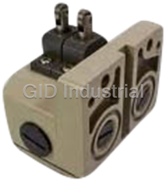

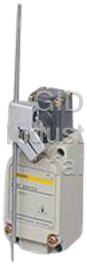


What they say about us
FANTASTIC RESOURCE
One of our top priorities is maintaining our business with precision, and we are constantly looking for affiliates that can help us achieve our goal. With the aid of GID Industrial, our obsolete product management has never been more efficient. They have been a great resource to our company, and have quickly become a go-to supplier on our list!
Bucher Emhart Glass
EXCELLENT SERVICE
With our strict fundamentals and high expectations, we were surprised when we came across GID Industrial and their competitive pricing. When we approached them with our issue, they were incredibly confident in being able to provide us with a seamless solution at the best price for us. GID Industrial quickly understood our needs and provided us with excellent service, as well as fully tested product to ensure what we received would be the right fit for our company.
Fuji
HARD TO FIND A BETTER PROVIDER
Our company provides services to aid in the manufacture of technological products, such as semiconductors and flat panel displays, and often searching for distributors of obsolete product we require can waste time and money. Finding GID Industrial proved to be a great asset to our company, with cost effective solutions and superior knowledge on all of their materials, it’d be hard to find a better provider of obsolete or hard to find products.
Applied Materials
CONSISTENTLY DELIVERS QUALITY SOLUTIONS
Over the years, the equipment used in our company becomes discontinued, but they’re still of great use to us and our customers. Once these products are no longer available through the manufacturer, finding a reliable, quick supplier is a necessity, and luckily for us, GID Industrial has provided the most trustworthy, quality solutions to our obsolete component needs.
Nidec Vamco
TERRIFIC RESOURCE
This company has been a terrific help to us (I work for Trican Well Service) in sourcing the Micron Ram Memory we needed for our Siemens computers. Great service! And great pricing! I know when the product is shipping and when it will arrive, all the way through the ordering process.
Trican Well Service
GO TO SOURCE
When I can't find an obsolete part, I first call GID and they'll come up with my parts every time. Great customer service and follow up as well. Scott emails me from time to time to touch base and see if we're having trouble finding something.....which is often with our 25 yr old equipment.
ConAgra Foods