

 Manufacturers
OMRON V680- D1KP52MT

Description
Omron V680-D1KP52MT RFID Systems with ISO/IEC 18000-3 (ISO/IEC15693) Compliance
Part Number
V680- D1KP52MT
Price
Request Quote
Manufacturer
OMRON
Lead Time
Request Quote
Category
RFID Modules
Specifications
General
In-house standard for antenna oil resistance (former JEM1030 standard equivalent to IP67g) *4
Ambient operating humidity
35 to 95%
Ambient operating temperature (during transmission)
- 25 to 85 °C (with no icing)
Ambient storage temperature (during data backup)
-40 to 125°C (with no icing) Heat resistance: 1,000 thermal cycles each of 30 minutes at -10°C/ 150°C, Hightemperature storage: 1,000 hours at 150°C *2 200 thermal cycles each of 30 minutes at -10°C/180°C, Hightemperature storage: 200 hours at 180°C 3
Appearance
8 dia. × 5 mm
Data retention
time 1 10 years after writing (85 °C max.)
Degree of protection
IEC 60529, IP68
Materials
mase: PPS resin Filling: Epoxy resin
Memory capacity
1,000 byte (user area)
Memory type
EEPROM
Metallic compatibility
Yes
Shock resistance
500 m/s2 in X, Y, and Z directions 3 times each (18 times in total)
Vibration resistance
10 to 2,000 Hz, 1.5-mm double amplitude at 150 m/s2 acceleration with 10 sweeps in X, Y, and Z directions for 15 minutes each
Weight
Approx. 0.5 g
Write endurance
100,000 times per block (at 25 °C)
Features
- ?High-speed communications and highly reliable communications provided with an electromagnetic induction system and unique technology.
- Antennas and RF Tags with excellent environmental resistance.
- Complies with FCC Standards and R&TTE Directive.
- Visualizes the communications status for simple analysis of the operating environment.
- Wide line-up of ultra-compact, long-life RF Tags, with capacities from 1 to 32 kbytes.
Datasheet

Extracted Text
Max. extended length: 30.5 m Max. extended length: 62.5 m Amplifier Unit ID Controller Extension Cable DeviceNet I/O Connection Interface Amplifier-integrated Host Device Antenna RF Tag Cable Controller RFID System V680 Series CSM_V680 Series_DS_E_1_1 RFID Systems with ISO/IEC 18000-3 (ISO/IEC15693) Compliance • High-speed communications and highly reliable communications provided with an electromagnetic induction system and unique technology. Antennas and RF Tags with excellent environmental resistance. Wide line-up of ultra-compact, long-life RF Tags, with capacities from 1 to 32 kbytes. Visualizes the communications status for simple analysis of the operating environment. Complies with FCC Standards and R&TTE Directive. System Configuration Connect V680 Antennas and Amplifier Units to a V680-series Controller, and read or write data from or to RF Tags. OMRON Programmable Controller Standard Programmable Personal computer CJ/CS/NJ Series Controller Standard 1-channel Controller Standard 2-channel Controller CS/CJ-series PLC ID Sensor Units (1 or 2 channels) V680-CA5D01-V2 V680-CA5D02-V2 CJ1W-V680C11/C12 CS1W-V680-C11/C12 The V680-H01-V2 can be used only with 1-channel Controllers or ID Sensor Units. V680-A60 V700-A40/41/42/43/44/45 V700-A40-W Cable length (2/5/10) M Cable length (2/3/5/10/20/30) M Cable length (2/5/10/20/30) M The maximum extendable cable length is 40 m. The maximum (Not including the Amplifier.) extendable cable Do not connect more than two length is 30 m. Extension Cables to each other. (not including the Amplifier) Two Extension Cables For 1-Kbyte RF Tags cannot be connected V680-HA63A to each other. For 2-, 8-, or 32-Kbyte RF Tags DeviceNet ID Slave V680-HA63B ID Flag Sensor V680-HAM42-DRT V680-HAM91/-HAM81 PROFIBUS ID Slave Cable length (0.5/5/10) M (NPN output/PNP output) V680-HAM42-PRT ∗ V680-H01-V2 Cable length 0.5 M V680-HS51 V680-HS52 V680-HS63 V680-HS65 Cable length 2 M Cable length (2/12.5) M Cable length (2/12.5) M Cable length (2/12.5) M An Amplifier is not ∗ required. It is built in. 1-kbyte RF Tags 2-kbyte RF Tags V680-D2KF67 V680-D1KP53M V680-D1KP66T V680-D1KP58HT V680-D2KF67M V680-D1KP66MT V680-D1KP52M-BT01 V680-D2KF52M-BT01 V680-D1KP52MT V680-D1KP54T V680-D1KP66T-SP V680-D1KP52M-BT11 V680-D2KF52M V680-D2KF52M-BT11 8-kbyte RF Tags 32-kbyte RF Tags V680-D8KF67 V680-D8KF68 V680-D32KF68 V680-D8KF67M * For information on the combinations that can be used, refer to Combinations of Amplifier Units, Antennas, and RF Tags on pages 2 to 3. 1 Host Device RF Tags Handheld Reader Writer V680 Series Handheld Type Handheld Terminal Standard Programmable Controller SYSMAC Series Personal computer (Recommended: Psion Teklogix Handheld Terminal) Handheld Reader Writer Standard Serial AC Adapter USB Handheld Reader Writer for Psion Teklogix Handheld Terminal Handheld Reader Writer (order separately) V680-CHUD V680-CH1D-PSI V680-CH1D V600-A22 ∗ 1-kbyte RF Tags 2-kbyte RF Tags V680-D2KF67 V680-D1KP53M V680-D1KP66T V680-D1KP58HT V680-D2KF67M V680-D1KP66MT V680-D1KP52M-BT01 V680-D2KF52M-BT01 V680-D1KP52MT V680-D1KP54T V680-D1KP52M-BT11 V680-D2KF52M V680-D2KF52M-BT11 V680-D1KP66T-SP 8-kbyte RF Tags 32-kbyte RF Tags V680-D8KF67 V680-D8KF68 V680-D32KF68 V680-D8KF67M Note: Certification for radio wave regulations has been acquired for Japan, Europe, the USA, Canada, Mexico, Singapore, Malaysia, the Philippines, China, Taiwan, and Korea, for easy application overseas. Contact your OMRON sales representative for details on whether application is supported in other countries. The latest information on the status of certification for radio wave regulations in various countries can be confirmed on the OMRON website. * For information on the combinations that can be used, refer to Combinations of Amplifier Units, Antennas, and RF Tags on pages 2 to 3. Combinations of Amplifier Units, Antennas, and RF Tags 1-kbyte RF Tags EEP-ROM 1-kbyte V680- V680- V680- V680- V680- V680- V680- V680- D1KP66T- D1KP52M- Amplifier Unit Antenna D1KP52MT D1KP53M D1KP54T D1KP66T D1KP66MT D1KP58HT SP BT@1 V680-HS51 Yes Yes Yes V680-HA63A V680-HS52-@ Yes Yes Yes Yes Yes Yes Yes V680-HAM42-DRT V680-HS63-@ Yes* Yes Yes Yes Yes V680-HAM@1 V680-HS65-@ Yes Yes Yes Yes V680-HS63-W Yes* Yes Y es Yes V680-HAM42-PRT V680-HS65-W Yes Yes Yes V680-H01-V2 (Antenna with Built-in Amplifier) Yes Y es V680-CH@D (Handheld Reader Writer) Yes Yes Yes Yes Yes Yes 2 V680 Series 2-kbyte RF Tags FRAM 2-kbyte V680- V680- V680- V680- Amplifier Unit Antenna D2KF52M- D2KF52M D2KF67 D2KF67M BT@1 V680-HS51 Yes Yes V680-HA63B V680-HS52-@ Yes Yes Yes Yes V680-HAM42-DRT V680-HS63-@ Yes* Yes Yes V680-HAM@1 V680-HS65-@ Yes Yes V680-HS63-W Yes Yes V680-HAM42-PRT V680-HS65-W Yes Yes V680-H01-V2 (Antenna with Built-in Amplifier) Yes V680-CH@D (Handheld Reader Writer) Yes Yes Yes 8-kbyte RF Tags FRAM 8-kbyte V680- V680- V680- Amplifier Unit Antenna D8KF67 D8KF67M D8KF68 V680-HS51 V680-HA63B V680-HS52-@ Yes Yes V680-HAM42-DRT V680-HS63-@ Yes Yes Yes V680-HAM@1 V680-HS65-@ Yes Yes Yes V680-HS63-W Yes V680-HAM42-PRT V680-HS65-W Yes V680-H01-V2 (Antenna with Built-in Amplifier) Yes Yes V680-CH@D (Handheld Reader Writer) Yes Yes Yes 32-kbyte RF Tags FRAM 32-kbyte V680- Amplifier Unit Antenna D32KF68 V680-HS51 V680-HA63B V680-HS52 V680-HAM42-DRT V680-HS63 Yes V680-HAM@1 V680-HS65 Yes V680-HS63-W Yes V680-HAM42-PRT V680-HS65-W Yes V680-H01-V2 (Antenna with Built-in Amplifier) Yes V680-CH@D (Handheld Reader Writer) Yes Note: For details, refer to the relevant user’s manual (Z248, Z249, Z262, Z271, Z272, Z278, and Z279). * When using the V680-D1KP52MT or V680-D2KF52M embedded in metal, use the V680-HS51/-HS52 Antenna. Communications will not be possible if the V680-HS63 Antenna is used. Communications will not be possible if the V680-HS65 Antenna is used with the V680-D1KP52MT, V680-D1KP53M, or V680-D2KF52M. Transmission is also possible with RF Tags other than those of the V680 Series as long as they comply with ISO/IEC 18000-3 (ISO/IEC 15693). However, transmission with RF Tags other than those of the V680 Series cannot be assured. The user must confirm transmission capabilities carefully prior to use. 3 V680 Series Ordering Information RF Tag Type Memory capacity Appearance Size Metallic compatibility Model For embedding in metallic or 8 dia. × 5 mm V680-D1KP52MT non-metallic surface For embedding in metallic or 10 dia. × 4.5 mm V680-D1KP53M non-metallic surface For flush mounting on non- 20 dia. × 2.7 mm V680-D1KP54T metallic surface For flush mounting on metallic V680-D1KP66MT surface 34 × 34 × 3.5 mm 1 kbyte For flush mounting on non- V680-D1KP66T metallic surface For flush mounting on non- 95 × 36.5 × 6.5 mm V680-D1KP66T-SP metallic surface For flush mounting on non- 80 dia. × t10 mm V680-D1KP58HT metallic surface M10 × 12 mm V680-D1KP52M-BT01 * Battery-less For mounting as bolts M8 × 12 mm V680-D1KP52M-BT11 * For embedding in metallic or 8 dia. × 5 mm V680-D2KF52M non-metallic surface For flush mounting on metallic V680-D2KF67M surface 40 × 40 × 4.5 mm 2 kbytes For flush mounting on non- V680-D2KF67 metallic surface M10 × 12 mm V680-D2KF52M-BT01 * For mounting as bolts M8 × 12 mm V680-D2KF52M-BT11 * For flush mounting on metallic V680-D8KF67M surface 40 × 40 × 4.5 mm For flush mounting on non- V680-D8KF67 8 kbytes metallic surface V680-D8KF68 For flush mounting on non- 86 × 54 × 10 mm metallic surface 32 kbytes V680-D32KF68 * Place orders in units of boxes (containing 20 units). 4 V680 Series Antenna (Detachable Amplifier Unit Type) Type Appearance Size Cable length Model Standard cable, 2 m V680-HS52-W 2M waterproof 12.5 m V680-HS52-W 12.5M connector M22 × 65 mm Flexible cable, 2 m V680-HS52-R 2M nonwaterproof 12.5 m V680-HS52-R 12.5M connector Cylindrical Standard cable, nonwaterproof M12 × 35 mm 2 m V680-HS51 2M connector Standard cable, 2 m V680-HS63-W 2M waterproof 12.5 m V680-HS63-W 12.5M connector 40 × 53 × 23 mm Flexible cable, 2 m V680-HS63-R 2M nonwaterproof 12.5 m V680-HS63-R 12.5M connector Square Standard cable, 2 m V680-HS65-W 2M waterproof 12.5 m V680-HS65-W 12.5M connector 100 × 100 × 30 mm Flexible cable, 2 m V680-HS65-R 2M nonwaterproof 12.5 m V680-HS65-R 12.5M connector Antenna with Built-in Amplifier Type Appearance Size Cable length Model Square 250 × 200 × 35 mm 0.5 m * V680-H01-V2 * Use an Antenna Cable to connect the Antenna to the Controller. The maximum cable length is 30.5 m. Amplifier Unit Type Appearance Size Cable length Model 0.5 m V680-HA63A 0.5M For 1-kbyte memory 5 m V680-HA63A 5M 10 m V680-HA63A 10M 25 × 40 × 65 mm 0.5 m V680-HA63B 0.5M For 2-/8-/32-kbyte memory 5 m V680-HA63B 5M 10 m V680-HA63B 10M ID Controller No. of connectable Type Appearance Size Transmission interface Model Amplifiers Single V680-CA5D01-V2 RS232C, DC power supply 105 × 90 × 65 mm RS422/RS485 Dual V680-CA5D02-V2 5 V680 Series ID Sensor Units No. of unit Current consumption (A) External Type Appearance Connected ID System numbers Model power supply 5 V 24 V External used 1 unit 1 Head 0.26 0.13 * − CJ1W-V680C11 number CJ V680 Special − Series I/O Unit 2 unit 2 Heads 0.32 0.26 − CJ1W-V680C12 number No. of unit Current consumption (A) External Type Appearance Connected ID System numbers Model power supply 5 V 26 V External used 1 unit 1 Head − 0.26 0.13 * − CS1W-V680C11 number CS V680 Special Series I/O Unit 2 unit 2 Heads 24 VDC 0.32 − 0.36 CS1W-V680C12 number * When connected to the V680-H01: 0.28 A Amplifier-integrated Controller (DeviceNet ID Slave/PROFIBUS ID Slave) Appearance Size Network Compatibility Model DeviceNet V680-HAM42-DRT 65 × 65 × 65 mm PROFIBUS V680-HAM42-PRT Amplifier-integrated Controllers (ID Flag Sensors) Type Appearance Size Model NPN V680-HAM91 output 90 × 30 × 65 mm PNP V680-HAM81 output Special Interface Cables (for V680-HAM91 and V680-HAM81) Cable length Model Appearance 2 m V680-A60 2M 5 m V680-A60 5M 10 m V680-A60 10M Note: 1. The connectors are not waterproof. 2. The cable length can be extended to a maximum of 10 m. 3. Normally two Interface Cables are required for 1 Unit. If you do not need to write to ID Tags, or use the address shift or noise check functions, then one Interface Cable is sufficient. Handheld Reader Writers Name Appearance Model Model with standard serial connector V680-CH1D Model with USB connector and 0.8-m cable V680-CHUD 0.8M Model with USB connector and 1.9-m cable V680-CHUD 1.9M Models for Psion Teklogix Handheld Terminal V680-CH1D-PSI AC Adapter (for V680-CH1D) V600-A22 6 V680 Series Accessories (Order Separately) RF Tag Attachment Type Appearance Model For the V680-D1KP66T V600-A86 For the V680-D@KF68 V680-A81 To mount the V680- V680-A80 D1KP58HT For the V680-D1KP54T V700-A80 Amplifier Unit Special Extension Cable (Amplifier Unit to Controller) Cable length Appearance Model 2 m V700-A40 2M 3 m V700-A41 3M 5 m V700-A42 5M 10 m V700-A43 10M 20 m V700-A44 20M 30 m V700-A45 30M Note: The cable can be extended up to 40 m. Up to two extension cables can be used. V680-H01 Antenna Special Cable (Antenna to Controller) Cable length Appearance Model 2 m V700-A40-W 2M 5 m V700-A40-W 5M 10 m V700-A40-W 10M 20 m V700-A40-W 20M 30 m V700-A40-W 30M Note: The cable can be extended up to 30 m. Only one extension cable can be used. RS-232C Communications Connector Name Model Connector Plug XM3B-0922-111 Connector Hood XM2S-0911 * An RS422/RS485 Communications Connector is attached to the Controller. ID Map Manager (for Windows XP) Type Model English version V680-A-IMMEG-P01 7 V680 Series Psion Teklogix Handheld Terminals We recommend connecting the V680/V680-CH-PSI Handheld Reader Writer to a Psion Teklogix WORKABOUT PRO-series Handheld Terminal. Psion Teklogix products can be purchased directly from OMRON. Handheld Terminal Set Name Configuration OMRON model number Handheld Terminal, Serial End Cap, hand strap, charger Handheld Terminal Set (English OS) V680-A-7527S-G3-EG-S (standard model), and High-capacity Battery * The Handheld Terminal Set includes the V600/V680 EasyAccess/CBAccess Demo Software preinstalled in a 7527S-G3 Psion Teklogix Handheld Terminal and the configuration parts listed above. Handheld Terminal Only Name Configuration Appearance OMRON model number Handheld Terminal, Serial End Cap, Handheld Terminal (English OS) and hand strap V680-A-7527S-G3-EG (Battery sold separately.) * The Handheld Terminal includes the V600/V680 EasyAccess/CBAccess Demo Software preinstalled in a 7527S-G3 Psion Teklogix Handheld Terminal and the con- figuration parts listed above. The High-capacity Battery is not included. Handheld Terminal Accessories Name Appearance Psion Teklogix model number OMRON model number High-capacity Battery WA3006 V680-A-WA3006 Charger (standard model) PS1050-G1 V680-A-CA1053 Charger (advanced model) WA4003-G2 V680-A-WA4003 Carrying Case WA6197-G2 V680-A-WA6197 Refer to the following website for detailed information on Psion Teklogix Handheld Terminals. http://www.psionteklogix.com/products/handheld/workaboutpro.htm 8 V680 Series Ratings and Performance RF Tag (1-kbyte Memory) Model V680- V680- V680- V680- V680- V680- Item D1KP52MT D1KP54T D1KP66T D1KP66MT D1KP53M D1KP66T-SP Memory capacity 1,000 byte (user area) Memory type EEPROM Data retention time *1 10 years after writing (85°C max.) Write endurance 100,000 times per block (at 25°C) Ambient operating −25 to 70°C temperature −25 to 85°C (with no icing) (with no icing) (during transmission) −40 to 125°C (with no icing) Ambient storage Heat resistance: 1,000 thermal cycles each of 30 minutes at −10°C/150°C, High- −40 to 125°C −40 to 110°C temperature temperature storage: 1,000 hours at 150°C *2 (with no icing) (with no icing) (during data backup) 200 thermal cycles each of 30 minutes at −10°C/180°C, High- temperature storage: 200 hours at 180°C *3 Ambient operating 35 to 95% humidity IEC 60529, IP68 Degree of protection IP67 In-house standard for antenna oil resistance (former JEM1030 standard equivalent to IP67g) *4 2 Vibration resistance 10 to 2,000 Hz, 1.5-mm double amplitude at 150 m/s acceleration with 10 sweeps in X, Y, and Z directions for 15 minutes each 2 Shock resistance 500 m/s in X, Y, and Z directions 3 times each (18 times in total) 10 dia. × 4.5 mm 95 × 36.5 × 6.5 mm Appearance 8 dia. × 5 mm 20 dia. × 2.7 mm 34 × 34 × 3.5 mm (DIN698373) (excluding protrusions) Case: PPS resin Case: PPS resin External resin: PFA Materials Filling: Epoxy Molding: PPS resin Filling: Epoxy Tag body: PPS resin resin resin Weight Approx. 0.5 g Approx. 2 g Approx. 6 g Approx. 7.5 g Approx. 1 g Approx. 20 g Metallic compatibility Yes No NoYes Yes No Note: For details, refer to the User's Manual (Cat. No. Z262). *1. Refer to the User's Manual (Cat. No. Z262) for data retention time for temperatures of 85°C or higher. If the V680 has been stored at 125°C or higher, write the data again even if the data does not need to be changed. *2. 150°C heat resistance: The heat resistance has been checked at 150°C for up to 1,000 hours, and thermal shock has been checked through testing 1,000 thermal cycles each of 30 minutes at −10/150°C. (Test samples: 22, defects: 0) *3. 180°C heat resistance: The heat resistance has been checked at 180°C for up to 200 hours, and thermal shock has been checked through testing 200 thermal cycles each of 30 minutes at −10°C/180°C. (Test samples: 22, defects: 0) *4. This OMRON in-house standard confirms resistance to cutting and other oils. It is equivalent to the former JEM1030 standard. RF Tag with 1-kbyte Memory with High-temperature Capability Item Model V680-D1KP58HT Memory capacity 1,000 bytes (user area) Memory type EEPROM Data retention time 10 years after writing * Write endurance 100,000 times per block (at 25°C) Ambient operating temperature −10 to 85°C (with no icing) (during transmission) −40 to 110°C (with no icing) Ambient storage temperature Heat resistance: 2,000 thermal cycles each of 30 minutes at room temperature/200°C (Refer to Heat Resistance, (during data backup) below, for details.) Ambient operating humidity No limits. Degree of protection IEC 60529, IP67 2 Vibration resistance 10 to 2,000 Hz, 1.5-mm double amplitude at 150 m/s acceleration with 10 sweeps in X, Y, and Z directions for 15 minutes each 2 Shock resistance 500 m/s in X, Y, and Z directions 3 times each (18 times in total) Materials PPS resin Weight Approx. 90 g * The data retention time at high temperatures (110 to 200°C) is 10 hours. Rewrite the data before 10 hours has lapsed. Heat Resistance Sufficient heat resistance has been confirmed by evaluation testing comprising 2,000 thermal cycles each of 30 minutes at room temperature/200°C. The lifetime of the V680-D1KP58HT is affected by high-temperature storage, due to the effects of high temperatures on internal components. For details on the relationship between heat resistance and lifetime, refer to the User’s Manual (Cat. No. Z262). 9 V680 Series RF Tag (2-kbyte Memory) Item Model V680-D2KF52M V680-D2KF67 V680-D2KF67M Memory capacity 2,000 bytes (user area) Memory type FRAM Data retention time *1 10 years after writing (55°C max.) Write endurance Access frequency per block *2: 10 billion times Ambient operating −25 to 85°C (with no icing) temperature Ambient storage −40 to 85°C (with no icing) temperature Ambient operating 35 to 95% 35 to 85% humidity IEC 60529, IP67 Degree of protection In-house standard for antenna oil resistance (former JEM1030 standard equivalent to IP67g) *3 2 10 to 2,000 Hz, 1.5-mm double amplitude at 150 m/s acceleration with 10 sweeps in X, Y, and Z directions for 15 Vibration resistance minutes each 2 Shock resistance 500 m/s in X, Y, and Z directions 3 times each (18 times in total) Appearance 8 dia. × 5 mm 40 × 40 × 4.5 mm Case: PPS resin Molding: PBT resin Materials Filling: Epoxy resin Filling: Epoxy resin Weight Approx. 0.5 g Approx. 6.5 g Approx. 7 g Metallic compatibility Yes NoYes Note: For details, refer to the User’s Manual (Cat. No. Z248). *1. Refer to the User's Manual (Cat. No. Z248) for data retention time for temperatures of 55°C or higher. *2. The total Read or Write communication frequency is called the access frequency. *3. This OMRON in-house standard confirms resistance to cutting and other oils. It is equivalent to the former JEM1030 standard. RF Tag with 8-/32-kbyte Memory Item Model V680-D8KF67 V680-D8KF67M V680-D8KF68 V680-D32KF68 Memory capacity 8,192 bytes (user area) 32,744 bytes (user area) Memory type FRAM Data retention time 10 years after writing (at 70°C max.) *1 Write endurance Access frequency per block *2: 10 billion times Ambient operating −20 to 85°C (with no icing) temperature Ambient storage −40 to 85°C (with no icing) temperature Ambient operating 35 to 85% humidity Degree of IEC 60529, IP67 protection In-house standard for antenna oil resistance (former JEM1030 standard equivalent to IP67g) *3 2 2 10 to 2,000 Hz, 1.5-mm double amplitude at 150 m/s 10 to 500 Hz, 1.5-mm double amplitude at 100 m/s Vibration acceleration with 10 sweeps in X, Y, and Z directions for 15 acceleration with 10 sweeps in X, Y, and Z directions for 11 resistance minutes each minutes each 2 Shock resistance 500 m/s in X, Y, and Z directions 3 times each (18 times in total) Dimensions 40 × 40 × 4.5 mm 86 × 54 × 10 mm Case: PBT resin Materials Filling: Epoxy resin Weight Approx. 8 g Approx. 8.5 g Approx. 50 g Metallic NoYes No *4 compatibility Note: For details, refer to the User’s Manual (Cat. No. Z248). *1. Refer to the User’s Manual (Cat. No. Z248) for data retention time for temperatures of 70°C or higher. *2. The total Read or Write communication frequency is called the access frequency. *3. This OMRON in-house standard confirms resistance to cutting and other oils. It is equivalent to the former JEM1030 standard. *4. Using the V680-A81 special attachment improves the influence of flush mounted on metallic surface. 10 V680 Series Bolt RF Tags (1-kbyte Memory) Item Model V680-D1KP52M-BT01 V680-D1KP52M-BT11 Memory capacity 1,000 bytes (user area) Memory type EEPROM Data retention time 10 years after writing (85°C max.) Write endurance 100,000 times per block (at 25°C) Ambient operating temperature −25 to 85°C (with no icing) (during transmission) Ambient storage temperature −40 to 125°C (with no icing) (during data backup) Ambient operating 35 to 95% humidity Degree of IP67 (IEC 60529 standard), In-house standard for oil resistance (Equivalent to former JEM standard IP67g.) protection 2 Vibration 10 to 2,000 Hz, 1.5-mm double amplitude at 150 m/s acceleration with 10 sweeps in X, Y, and Z directions for 15 minutes resistance each 2 Shock resistance 500 m/s in X, Y, and Z directions 3 times each (18 times in total) Bolt: SUS303, Materials Case (RF Tag): PPS resin, Filling (RF Tag): Epoxy resin Weight Approx. 25 g Approx. 10 g Bolt RF Tags (2-kbyte Memory) Item Model V680-D2KF52M-BT01 V680-D2KF52M-BT11 Memory capacity 2,000 bytes (user area) Memory type FRAM Data retention time 10 years after writing (at 55°C max.) Write endurance 10 billion reads/writes per block, Number of accesses*: 10 billion times Ambient operating temperature −25°C to 85°C (with no icing) (during transmission) Ambient storage temperature −40°C to 85°C (with no icing) (during data backup) Ambient operating 35 to 95% humidity Degree of IEC 60529, IP67 protection In-house standard for antenna oil resistance (former JEM1030 standard equivalent to IP67g) 2 Vibration 10 to 2,000 Hz, 1.5-mm double amplitude at 150 m/s acceleration with 10 sweeps in X, Y, and Z directions for 15 minutes resistance each 2 Shock resistance 500 m/s in X, Y, and Z directions 3 times each (18 times in total) Bolt: SUS303, Materials Case (RF Tag): PPS resin, Filling (RF Tag): Epoxy resin Weight Approx. 25 g Approx. 10 g * The number of accesses is the total number of communications for reading or writing. 11 V680 Series Cylindrical Antenna (Detachable Amplifier Unit Type) Model V680-HS51 (Standard Cable, V680-HS52-W (Standard Cable, V680-HS52-R (Standard Cable, Item Non-waterproof Connector) Waterproof Connector) Non-waterproof Connector) Ambient operating temperature −10°C to 60°C (with no icing) Ambient storage temperature −25°C to 75°C (with no icing) Ambient operating humidity 35% to 95% (with no condensation) Insulation resistance 20 MΩ min. (at 500 VDC) between the cable terminals and the case Dielectric strength 1,000 VAC (50/60 Hz) for 1 minute between the cable terminals and the case with a current leakage of 5 mA max. IP67 (IEC60529) IP67 (IEC60529) IP67 (IEC60529) In-house standard for antenna oil In-house standard for antenna oil In-house standard for antenna oil Degree of protection resistance (former JEM1030 standard resistance (former JEM1030 standard resistance (former JEM1030 standard equivalent to IP67g) (Antenna portion) *2 equivalent to IP67g) (Antenna portion) *1 equivalent to IP67g) (Antenna portion) *2 10 to 2,000 Hz variable vibration, 1.5-mm 2 2 double amplitude at 150 m/s 10 to 500 Hz variable vibration, 1.5-mm double amplitude at 100 m/s Vibration resistance acceleration, with 10 sweeps in X, Y, and acceleration, with 10 sweeps in X, Y, and Z directions for 8 minutes each Z directions for 15 minutes each 2 1,000 m/s in X, Y, and Z directions 3 2 Shock resistance 500 m/s in X, Y, and Z directions 3 times each (18 times in total) times each (18 times in total) Appearance M12 × 35 mm M22 × 65 mm Materials ABS, brass, epoxy resin filling Weight Approx. 55 g (with 2-m cable) Approx. 850 g (with 12.5-m cable) Note: For details, refer to the User’s Manual (Cat. No. Z248 or Z262). *1. The degree of protection for the Connector is IP67/IP65. This OMRON in-house standard confirms resistance to cutting and other oils. It is equivalent to the former JEM1030 standard. *2. The Connector is not waterproof. This OMRON in-house standard confirms resistance to cutting and other oils. It is equivalent to the former JEM1030 standard. Square Antenna (Detachable Amplifier Unit Type) Item Model V680-HS63-W (Standard Cable, Waterproof Connector) V680-HS63-R (Flexible Cable, Non-waterproof Connector) Ambient operating temperature −10°C to 60°C (with no icing) Ambient storage temperature −25°C to 75°C (with no icing) Ambient operating humidity 35% to 95% (with no condensation) Insulation resistance 20 MΩ min. (at 500 VDC) between the cable terminals and the case Dielectric strength 1,000 VAC (50/60 Hz) for 1 minute between the cable terminals and the case with a current leakage of 5 mA max. IP67 (IEC60529) IP67 (IEC60529) Degree of protection In-house standard for antenna oil resistance (former JEM1030 In-house standard for antenna oil resistance (former JEM1030 standard equivalent to IP67g) (Antenna portion) *1 standard equivalent to IP67g) (Antenna portion) *2 2 10 to 500 Hz variable vibration, 1.5-mm double amplitude at 100 m/s acceleration, with 10 sweeps in X, Y, and Z Vibration resistance directions for 11 minutes each 2 Shock resistance 500 m/s in X, Y, and Z directions 3 times each (18 times in total) Appearance 40 × 53 × 23 mm Materials ABS, epoxy resin filling Weight Approx. 850 g (with 12.5-m cable) Item Model V680-HS65-W (Standard Cable, Waterproof Connector) V680-HS65-R (Flexible Cable, Non-waterproof Connector) Ambient operating temperature −25°C to 70°C (with no icing) Ambient storage temperature −40°C to 85°C (with no icing) Ambient operating humidity 35% to 95% (with no condensation) Insulation resistance 20 MΩ min. (at 500 VDC) between the cable terminals and the case Dielectric strength 1,000 VAC (50/60 Hz) for 1 minute between the cable terminals and the case with a current leakage of 5 mA max. IP67 (IEC 60529) IP67 (IEC 60529) Degree of protection In-house standard for antenna oil resistance (former JEM1030 In-house standard for antenna oil resistance (former JEM1030 standard equivalent to IP67g) (Antenna portion) *1 standard equivalent to IP67g) (Antenna portion) *2 2 Vibration resistance 10 to 500 Hz variable vibration, 1.5-mm double amplitude at 100 m/s acceleration, with 10 sweeps in X, Y, and Z directions for 11 minutes each 2 Shock resistance 500 m/s in X, Y, and Z directions 3 times each (18 times in total) Appearance 100 × 100 × 30 mm Materials ABS, epoxy resin filling Weight Approx. 1,100 g (with 12.5-m cable) Note: For details, refer to the User’s Manual (Cat. No. Z248 or Z262). *1. The degree of protection for the Connector is IP67/IP65. This OMRON in-house standard confirms resistance to cutting and other oils. It is equivalent to the former JEM1030 standard. *2. The Connector is not waterproof. This OMRON in-house standard confirms resistance to cutting and other oils. It is equivalent to the former JEM1030 standard. 12 V680 Series Square Antenna with Built-in Amplifier Amplifier Unit Item Model V680-H01-V2 Item Model V680-HA63A V680-HA63B Ambient Ambient operating −10°C to 55°C (with no icing) operating −10°C to 55°C (with no icing) temperature temperature Ambient storage Ambient storage −35°C to 65°C (with no icing) −25°C to 65°C (with no icing) temperature temperature Ambient Ambient operating 35% to 85% (with no condensation) operating 35% to 85% (with no condensation) humidity humidity Insulation 20 MΩ min. (at 100 VDC) between the back Insulation 20 MΩ min. (at 500 VDC) between the cable resistance plate and the case resistance terminals and the case 1,000 VAC (50/60 Hz) for 1 minute between the Dielectric 1,000 VAC (50/60 Hz) for 1 minute between the cable Dielectric back plate and the case with a current leakage strength terminals and the case with a current leakage of 5 mA max. strength of 1 mA max. Degree of protection IP40 (IEC60529) *1 IP67/IP65 (IEC60529) *2 IEC 60529: IP63 (Mounting direction: 10 to 500 Hz variable vibration, 1.5-mm double Degree of protection Transmission surface facing up) 2 Vibration resistance amplitude at 100 m/s acceleration, with 10 sweeps in 10 to 150 Hz variable vibration, 0.7-mm double X, Y, and Z directions for 11 minutes each 2 Vibration resistance amplitude and 50 m/s acceleration with 10 sweeps in 2 Shock resistance 500 m/s in X, Y, and Z directions 3 times each (18 times in total) X, Y, and Z directions for 8 minutes each Appearance 25 × 40 × 65mm (not including projections) 2 Shock resistance 150 m/s in X, Y, and Z directions 3 times each Material Polycarbonate (PC) resin Appearance 200 × 250 × 40 mm Weight Approx. 650 g (with 10-m cable) Polycarbonate (PC) resin, ASA resin / Rear Material Cable length 5 m, 10 m Panel: Aluminum Transmittable RF Tags 1-kbyte memory 2-, 8-, 32-kbyte memory Weight Approx. 900 g Note: For details, refer to the User’s Manual (Cat. No. Z248 or Z262). Cable length 0.5 m *1. When connected to the V680-HS@@-R or V680-HS52-R. Note: For details, refer to the User’s Manual (Cat. No. Z248 or Z262). *2. When connected to the V680-HS@@-W or V680-HS52-W. (Not including the Connector on the Controller.) ID Controller Item Model V680-CA5D01-V2 V680-CA5D02-V2 Power supply voltage 24 VDC (−15% to +10%) (Power consumption) 15 W max., 0.8 A max. Communications Specifications RS-232C, RS-422, RS-485 Input Specifications (Input voltage) 24 VDC (+10% to −15%, including ripple) (PNP and NPN compatible) RST, TRG1, and TRG2 Output Specifications (Maximum switching capacity) 24 VDC (+10% to −15%, including ripple) RUN, BUSY/OUT3, ERROR/OUT4, OUT1, PNP and NPN compatible and OUT2 Ambient operating temperature −10 to 55°C (with no icing) Ambient storage temperature −25 to 65°C (with no icing) Ambient operating humidity 25% to 85% (with no condensation) 20 MΩ min. (at 500 VDC) applied as follows: Insulation resistance (1) Between power supply terminals and grounded case (2) Between ground and terminals 1,000 VAC (50/60 Hz) for 1 minute Dielectric strength (1) Between power supply terminals and grounded case (2) Between ground and terminals Degree of protection Panel mounted (equivalent to IP20) 2 10 to 150 Hz variable vibration, 0.2-mm double amplitude at 15 m/s acceleration, with 10 Vibration resistance sweeps in X, Y, and Z directions for 8 minutes each 2 Shock resistance 150 m/s Appearance 105 × 90 × 65 mm (not including projections) Material Polycarbonate (PC) resin, ABS resin Weight Approx. 300 g Connectable Amplifier Units12 Note: For details, refer to the User's Manual (Cat. No. Z249). USB Port The USB port is used for a simple connection with a personal computer using a USB cable. The port complies with USB 1.1, and the USB cable uses a series A or series mini-B connector. A USB port driver must be separately provided. Consult with your OMRON representative for details. When connected to a host device via USB, the communications will use 1:1 protocol regardless of the setting of DIP switches 3 to 9. The USB port is not used for control purposes. When building a system, be sure to provide an RS-232C port or RS-422/RS-485C port. 13 V680 Series ID Sensor Units Item Model CJ1W-V680C11 CJ1W-V680C12 CS1W-V680C11 CS1W-V680C12 Internal: 5 V 260 mA 320 mA 260 mA 320 mA Current Internal: consumpt 130 mA * 260 mA 125 mA * − 24 V/26 V ion External: 24 V−− − 360 mA Ambient operating 0 to 55°C temperature Ambient storage −20°C to 75°C temperature Ambient operating 10% to 90% (with no condensation) humidity Insulation resistance 20 mΩ min. at 500 VDC Dielectric strength 1,000 VAC for 1 minute Degree of protection Mounted in panel (IP30) 2 10 to 57 Hz variable vibration, 0.075-mm double amplitude and 57 to 150 Hz variable vibration at 9.8 m/s Vibration resistance acceleration, with 10 sweeps in X, Y, and Z directions for 8 minutes each 2 Shock resistance 147 m/s in X, Y, and Z directions 3 times each Appearance 31 × 65 × 90 mm (excluding protrusions) 35 × 130 × 101 mm (excluding protrusions) * When connected to the V680-H01: 280 mA. The V680-H01-V2 can be connected only to a 1-channel ID Sensor Unit. A 2-channel Unit cannot be used. Functional Specifications of ID Sensor Units Item Model CJ1W-V680C11 CJ1W-V680C12 CS1W-V680C11 CS1W-V680C12 Communications control Special protocol for CS, CJ and NJ PLCs protocol Number of Antenna 12 12 connections Supported commands: Read, Write, Bit Set/Bit Clear, Mask Bit Write, Calculation Write, Data Fill, Data Check, Number of Writes Control, Copy (CJ1W-V680C12 and CS1W-V680C12 only), Read with Error Correction/Write with Commands Error Correction, UID Read, and Noise Measurement. The following communications options are supported: Single trigger, Single auto, Repeat auto, FIFO trigger, FIFO repeat *, Multi-access trigger, and Multi-access repeat * Data transfer quantity 2,048 bytes max. (160 bytes/scan) (1) CPU watchdog timer Diagnostic function (2) Communications error detection with RF Tag (3) Antenna power supply error Monitoring/testing Tag communications can be tested in Test Mode. Status is displayed by LED indicators. functions Number of allocated 10 words 20 words 10 words 20 words words Note: For details, refer to the User's Manual (Cat. No. Z271). * Cannot be used for communications with the V680-D1KP@@. 14 V680 Series Amplifier-integrated Controller (DeviceNet ID Slave/PROFIBUS ID Slave) Item Model V680-HAM42-DRT V680-HAM42-PRT Network compatibility DeviceNet PROFIBUS DP-V0 Connectable Antennas One channel (V680-HS@@) Rated voltage 24 VDC (−15% to 10%) including 10% ripple (p-p) Power consumption 4 W max. (Current consumption of 200 mA max. at power supply voltage of 24 VDC) Ambient operating −10 to 55°C (with no icing) temperature Ambient storage −25 to 65°C (with no icing) temperature Ambient operating 25% to 85% (with no condensation; ambient operating temperature is 40°C max. at humidity of 85%) humidity Insulation resistance 20 MΩ min. (at 500 VDC) between all terminals excluding the ground terminal and the case Dielectric strength 1,000 VAC (50/60 Hz) for 1 minute between all terminals excluding the ground terminal and the case 2 10 to 150 Hz, 0.2-mm double amplitude at 15 m/s acceleration with 10 sweeps in X, Y and Z directions for 8 minutes Vibration resistance each 2 Shock resistance 150 m/s in X, Y, and Z directions 3 times each (18 times in total) Appearance 65 × 65 × 65 mm (excluding protrusions) Degree of protection IEC 60529, IP20 Materials Polycarbonate (PC) resin, ABS resin Weight Approx. 150 g Mounting DIN Track Note: 1. For details, refer to the User's Manual (Cat. No. Z278). 2. The number of words allocated in the master depends on the Access Mode. Amplifier-integrated Controllers (ID Flag Sensors) Item Model V680-HAM91 V680-HAM81 Rated voltage 24 VDC (−15% to +10%) including 10% ripple (p-p) Power consumption 3.5 W (24 VDC, 150 mA max. except external I/O line current) Transistor output Input specifications Short-circuit current: 3 mA (typical) (for short-circuit between IN terminal and 0 V), OFF voltage: 15 to 30 VDC, ON voltage: 0 to 5 VDC, Input impedance: 8.2 kΩ, Applied voltage: 30 VDC max. NPN open-collector output 30 VDC, 20 mA max., PNP open-collector output 30 VDC, 20 mA max., Output specifications Residual voltage: 2 V max. Residual voltage: 2 V max. Ambient operating −10 to 55°C (with no icing) temperature Ambient storage −25 to 65°C (with no icing) temperature Ambient operating 25% to 85% (with no condensation; ambient operating temperature is 40°C max. at humidity of 85%) humidity Insulation resistance 20 MΩ min. (at 500 VDC) between all terminals excluding the FG terminal and the case Dielectric strength 1,000 VAC (50/60 Hz) applied for 1 minute between all terminals excluding the FG terminal and the case 2 10 to 150 Hz, 0.2-mm double amplitude at 15 m/s acceleration with 10 sweeps in X, Y and Z directions for 8 minutes Vibration resistance each 2 Shock resistance 150 m/s in X, Y, and Z directions 3 times each (18 times in total) Appearance 90 × 30 × 65 mm (excluding protrusions) Degree of protection IEC 60529, IP40 Materials Polycarbonate (PC) resin, ABS resin Weight Approx. 130 g Mounting DIN Track Note: 1. For details, refer to the User’s Manual (Cat. No. Z279). 2. The connectors are not water resistant. If there is a possibility that water will be splashed onto the ID Sensor Unit, mount it inside of a control box. Also, be sure to use the V680 as a set with the V680-A60 Interface Cable (sold separately). 15 V680 Series Handheld Reader Writers Item Model V680-CHUD 0.8M V680-CHUD 1.9M V680-CH1D V680-CH1D-PSI Power supply voltage 5 VDC ± 5% (at the connector section of the product) Current consumption 500 mA max. (for a power supply voltage of 5.0 V) RS-232C (D-SUB 9-pin) Communications USB (Series A plug) Ver.1.1 compatible with IBM PC/ RS-232C (D-SUB 9-pin) specifications AT) Ambient operating temperature during 0 to +40°C communication Ambient storage −25 to +65°C temperature Ambient operating humidity during 35% to 85% (with no condensation) communication Insulation resistance 50 MΩ min. (at 500 VDC) between connector and case Dielectric strength 1,000 VAC, 50/60 Hz for 1 min (leakage current: 1 mA max.) between connectors and case Degree of protection IEC 60529: IP63 * 2 Destruction: 10 to 150 Hz variable vibration, 0.2-mm double amplitude and 15 m/s acceleration with 10 sweeps for Vibration resistance 8 min each in 6 directions 2 Shock resistance Destruction: 150 m/s , 3 times each in X, Y, and Z directions Approx. 110 g Approx. 140 g Approx. 170 g Approx. 120 g Weight (including connector and (including connector and (including connector and (including connector and cable) cable) cable) cable) Cable length 0.8 m 1.9 m 2.5 m 0.8 m Note: Refer to the User’s Manual (Cat. No. Z272) for details. Contact your OMRON sales representative for details on drivers for Windows. * This does not include the connector section. The main unit is not resistant to chemical or oils. AC Adapter (for V680-CH1D) Item Model V600-A22 Input voltage 100 to 120 VAC at 50/60 Hz Input current AC: 300 mA (at load current of 2.0 A) Output voltage DC5V ± 0.25V Ambient operating 0 to +40°C temperature Ambient storage −20 to +85°C (with no icing) temperature Ambient operating 5% to 95% (with no condensation) humidity Insulation resistance 100 MΩ min. (at 500 VDC) between input terminals and output terminals Dielectric strength 2,000 V for 1 minute between input terminals and output terminals with a current leakage of 10 mA max. Weight Approx. 70 g Applicable standards UL 16 V680 Series Communication Specifications ID Controllers (V680-CA5D01-V2/V680-CA5D02-V2) RF Tag (1-kbyte Memory) Transmission Recommended combination Transmission Function distance RF Tag and Antenna mounting conditions RF Tag Antenna (unit: mm) V680-D1KP52MT V680-HS51 V680-D1KP52MT Read 0.5 to 6.5 distance (axial deviation ±2) Non-metallic Resin, V680-HS51 plastic, wood, etc. Write 0.5 to 6.0 Metallic distance (axial deviation ±2) V680-HS52 V680-D1KP52MT Read 0 to 9.0 distance (axial deviation ±2) Non-metallic Resin, plastic, V680-HS52 wood, etc. Write 0 to 8.5 distance (axial deviation ±2) *2 Non-metallic V680-HS63 V680-HS63 Read 0 to 12.0 Non-metallic distance (axial deviation ±2) Resin, plastic, wood, etc. Write 0 to 9.5 V680- D1KP52MT distance (axial deviation ±2) *2 Non-metallic V680-D1KP52MT V680-HS51 Read 0.5 to 3.5 *1 Metallic (embedded in metallic distance (axial deviation ±2) surface: steel) V680-HS51 Write 0.5 to 3.0 *1 Metallic distance (axial deviation ±2) V680-D1KP52MT V680-HS52 Read 0 to 4.5 *1 Metallic distance (axial deviation ±2) V680-HS52 Write 0 to 4.0 *1 *2 Non-metallic distance (axial deviation ±2) V680-D1KP52MT V680-D1KP53M V680-HS51 V680-D1KP53M Read 0.5 to 6.5 distance (axial deviation ±2) Non-metallic Resin, V680-HS51 plastic, Write 0.5 to 6.0 wood, etc. Metallic distance (axial deviation ±2) V680-HS52 V680-D1KP53M Read 0 to 9.0 distance (axial deviation ±2) Non-metallic Resin, V680-HS52 plastic, wood, etc. Write 0 to 8.5 distance (axial deviation ±2) *2 Non-metallic V680-D1KP53M V680-HS51 Read 0.5 to 3.5 *1 (embedded in metallic Metallic distance (axial deviation ±2) surface : steel) V680-HS51 Write 0.5 to 3.0 *1 Metallic distance (axial deviation ±2) V680-D1KP53M V680-HS52 Read 0 to 4.5 *1 Metallic distance (axial deviation ±2) V680-HS52 Write 0 to 4.0 *1 *2 Non-metallic distance (axial deviation ±2) V680-D1KP53M *1. When using the V680-D1KP52MT/-D1KP53M embedded in metal, use the V680-HS51/-HS52 Antenna. Communications will not be possible with a V680-HS63 Antenna. *2. The Antenna can be mounted in metal, but the communications distance will decrease compared to mounting in nonmetal. Confirm performance using the actual devices before actual operation. 17 V680 Series Recommended combination Transmission Function distance RF Tag and Antenna mounting conditions RF Tag Antenna (unit: mm) V680-D1KP54T V680-D1KP54T V680-HS52 Read 0 to 17.0 *1 distance (axial deviation ±2) Non-metallic Resin, V680-HS52 plastic, wood, etc. Write 0 to 15.0 *1 distance (axial deviation ±2) *2 Non-metallic V680-HS63 V680-HS63 Read 0 to 24.0 *1 distance (axial deviation ±10) Non-metallic Resin, plastic, wood, etc. Write 0 to 20.0 *1 V680-D1KP54T distance (axial deviation ±10) *2 Non-metallic V680-HS65 V680-HS65 Read 0 to 33.0 *1 distance (axial deviation ±10) Non-metallic Resin, plastic, wood, etc. Write 0 to 28.0 *1 V680-D1KP54T distance (axial deviation ±10) Metallic V680-D1KP66T V680-HS52 V680-D1KP66T Read 0 to 17.0 *1 Non-metallic Resin, distance (axial deviation ±2) plastic, wood, etc. V680-HS52 Write 0 to 17.0 *1 distance (axial deviation ±2) *2 Non-metallic V680-HS63 V680-HS63 Read 0 to 30.0 *1 Non-metallic Resin, distance (axial deviation ±10) plastic, wood, etc. Write 0 to 25.0 *1 V680- D1KP66T distance (axial deviation ±10) *2 Non-metallic V680-HS65 V680-HS65 Read 0 to 47.0 *1 Non-metallic distance (axial deviation ±10) Resin, plastic, wood, etc. Write 0 to 42.0 *1 V680- distance (axial deviation ±10) D1KP66T Metallic V680-H01-V2 V680-H01-V2 V680-D1KP66T Read 0 to 100.0 *1 distance (axial deviation ±2) Write 0 to 100.0 *1 distance (axial deviation ±2) Non-metallic *2 Non-metallic Note: When mounting the V680-HS65, be sure to attach the Mounting Brackets at the base of the Antenna. The enclosed Mounting Brackets do not need to be used, however, if the mounting brackets on the Antenna are metal plates and their dimensions are larger than the dimensions of the Antenna (100 × 100 mm). For details, refer to the User’s Manual (Cat. No. Z248 or Z262). *1. The transmission distance may be reduced if the V680-D1KP66T/-D1KP54T is mounted onto a metallic surface. Refer to the User's Manual (Cat. No. Z262) for details. *2. The Antenna can be mounted in metal, but the communications distance will decrease compared to mounting in nonmetal. Confirm performance using the actual devices before actual operation. 18 V680 Series Recommended combination Transmission Function distance RF Tag and Antenna mounting conditions RF Tag Antenna (unit: mm) V680-D1KP66MT V680-HS52 V680-D1KP66MT Read 0 to 16.0 (flush-mounted on metallic distance (axial deviation ±2) surface: steel) V680-HS52 Write 0 to 14.0 distance (axial deviation ±2) *2 Non-metallic Metallic V680-HS63 V680-HS63 Read 0 to 25.0 Metallic distance (axial deviation ±10) V680- Write 0 to 20.0 D1KP66MT distance (axial deviation ±10) *2 Non-metallic V680-HS65 V680-HS65 Read 0 to 25.0 Metallic distance (axial deviation ±10) Write 0 to 20.0 V680- D1KP66MT distance (axial deviation ±10) Metallic V680-D1KP66T-SP V680-HS52 V680-D1KP66T-SP Read 0 to 15.0 *1 Resin, Non-metallic distance (axial deviation ±2) plastic, wood, etc. V680-HS52 Write 0 to 15.0 *1 distance (axial deviation ±2) *2 Non-metallic V680-HS63 V680-HS63 Read 0 to 25.0 *1 V680-HS63 distance (axial deviation ±10) Resin, plastic, wood, etc. V680- Write 0 to 20.0 *1 D1KP66T-SP distance (axial deviation ±10) *2 Non-metallic V680-HS65 V680-HS65 Read 0 to 42.0 *1 Non-metallic distance (axial deviation ±10) Resin, plastic, wood, etc. Write 0 to 37.0 *1 V680- D1KP66T-SP distance (axial deviation ±10) Metallic Note: When mounting the V680-HS65, be sure to attach the Mounting Brackets at the base of the Antenna. The enclosed Mounting Brackets do not need to be used, however, if the mounting brackets on the Antenna are metal plates and their dimensions are larger than the dimensions of the Antenna (100 × 100 mm). For details, refer to the User’s Manual (Cat. No. Z248 or Z262). *1. The transmission distance may be reduced if the V680-D1KP66T-SP is mounted onto a metallic surface. Refer to the User’s Manual (Cat. No. Z262) for details. *2. The Antenna can be mounted in metal, but the communications distance will decrease compared to mounting in nonmetal. Confirm performance using the actual devices before actual operation. High-temperature RF Tag (1-kbyte Memory) Transmission Recommended combination Transmission Function distance RF Tag and Antenna mounting conditions RF Tag Antenna (unit: mm) V680-D1KP58HT V680-H01-V2 V680-H01-V2 Read V680-D1KP58HT distance 0 to 150.0 *1 Resin, Non-metallic (axial deviation ±10) plastic, wood, etc. Write distance *2 Non-metallic *1. The transmission distance may be reduced if the V680-D1KP58HT is mounted onto a metallic surface. Refer to the User’s Manual (Cat. No. Z262) for details. *2. The Antenna can be mounted in metal, but the communications distance will decrease compared to mounting in nonmetal. Confirm performance using the actual devices before actual operation. 19 V680 Series RF Tag (2-kbyte Memory) Transmission Recommended combination Transmission Function distance RF Tag and Antenna mounting conditions RF Tag Antenna (unit: mm) V680-D2KF52M V680-HS51 V680-D2KF52M Read 0.5 to 5.5 Non-metallic distance (axial deviation ±2) Resin, plastic, V680-HS51 wood, etc. Write 0.5 to 5.5 distance (axial deviation ±2) Metallic V680-HS52 V680-D2KF52M Read 0 to 8.0 Non-metallic distance (axial deviation ±2) Resin, plastic, V680-HS52 wood, etc. Write 0 to 8.0 distance (axial deviation ±2) *2 Non-metallic V680-HS63 V680-HS63 Read 0 to 9.5 Non-metallic distance (axial deviation ±2) Resin, plastic, wood, etc. Write 0 to 9.5 V680- D2KF52M distance (axial deviation ±2) *2 Non-metallic V680-D2KF52M V680-HS51 Read 0 to 3.5 Metallic (embedded in metallic distance (axial deviation ±2) surface: steel) V680-HS51 Write 0 to 3.5 Metallic distance (axial deviation ±2) V680-D2KF52M V680-HS52 Read 0 to 3.0 Metallic distance (axial deviation ±2) V680-HS52 Write 0 to 3.0 *2 Non-metallic distance (axial deviation ±2) V680-D2KF52M V680-D2KF67 V680-HS52 V680-D2KF67 Read 0 to 17.0 *1 Non-metallic distance (axial deviation ±2) Resin, plastic, wood, etc. V680-HS52 Write 0 to 17.0 *1 distance (axial deviation ±2) *2 Non-metallic V680-HS63 V680-HS63 Read 7 to 30.0 *1 Non-metallic Resin, distance (axial deviation ±10) plastic, wood, etc. Write 7 to 30.0 *1 V680- D2KF67 distance (axial deviation ±10) *2 Non-metallic V680-HS65 V680-HS65 Read 0 to 42.0 *1 Non-metallic distance (axial deviation ±10) Resin, plastic, wood, etc. Write 0 to 42.0 *1 V680- D2KF67 distance (axial deviation ±10) Metallic V680-H01-V2 V680-H01-V2 V680-D2KF67 Read 0 to 100.0 *1 distance (axial deviation ±10) Write 0 to 100.0 *1 distance (axial deviation ±10) Non-metallic *2 Non-metallic Note: When mounting the V680-HS65, be sure to attach the Mounting Brackets at the base of the Antenna. The enclosed Mounting Brackets do not need to be used, however, if the mounting brackets on the Antenna are metal plates and their dimensions are larger than the dimensions of the Antenna (100 × 100 mm). For details, refer to the User’s Manual (Cat. No. Z248 or Z262). *1. The transmission distance may be reduced if the V680-D2KF67 is mounted onto a metallic surface. Refer to the User’s Manual (Cat. No. Z248) for details. *2. The Antenna can be mounted in metal, but the communications distance will decrease compared to mounting in nonmetal. Confirm performance using the actual devices before actual operation. 20 V680 Series Recommended combination Transmission Function distance RF Tag and Antenna mounting conditions RF Tag Antenna (unit: mm) V680-D2KF67M V680-HS52 V680-D2KF67M Read 0 to 16.0 (flush-mounted on metallic distance (axial deviation ±2) surface: steel) Metallic V680-HS52 Write 0 to 16.0 distance (axial deviation ±2) * Non-metallic V680-HS63 V680-HS63 Read 6 to 25.0 Metallic distance (axial deviation ±10) Write 6 to 25.0 V680- distance (axial deviation ±10) D2KF67M * Non-metallic V680-HS65 V680-HS65 Read 0 to 25.0 Metallic distance (axial deviation ±10) Write 0 to 25.0 V680- D2KF67M distance (axial deviation ±10) Metallic Note: When mounting the V680-HS65, be sure to attach the Mounting Brackets at the base of the Antenna. The enclosed Mounting Brackets do not need to be used, however, if the mounting brackets on the Antenna are metal plates and their dimensions are larger than the dimensions of the Antenna (100 × 100 mm). For details, refer to the User’s Manual (Cat. No. Z248 or Z262). * The Antenna can be mounted in metal, but the communications distance will decrease compared to mounting in nonmetal. Confirm performance using the actual devices before actual operation. RF Tag (8-/32-kbyte Memory) Transmission Recommended combination Transmission Function distance RF Tag and Antenna mounting conditions RF Tag Antenna (unit: mm) V680-D8KF67 V680-HS52 V680-D8KF67 Read 0 to 17.0 *1 Non-metallic distance (axial deviation ±2) Resin, plastic, V680-HS52 wood, etc. Write 0 to 17.0 *1 distance (axial deviation ±2) *2 Non-metallic V680-HS63 V680-HS63 Read 0 to 30.0 *1 Non-metallic Resin, distance (axial deviation ±10) plastic, wood, etc. Write 0 to 30.0 *1 V680- D8KF67 distance (axial deviation ±10) *2 Non-metallic V680-HS65 V680-HS65 Read 0 to 42.0 *1 Non-metallic distance (axial deviation ±10) Resin, plastic, wood, etc. Write 0 to 42.0 *1 V680- D8KF67 distance (axial deviation ±10) Metallic V680-H01-V2 V680-H01-V2 V680-D8KF67 Read 0 to 100.0 *1 distance (axial deviation ±10) Write 0 to 100.0 *1 distance (axial deviation ±10) Non-metallic *2 Non-metallic Note: When mounting the V680-HS65, be sure to attach the Mounting Brackets at the base of the Antenna. The enclosed Mounting Brackets do not need to be used, however, if the mounting brackets on the Antenna are metal plates and their dimensions are larger than the dimensions of the Antenna (100 × 100 mm). For details, refer to the User’s Manual (Cat. No. Z248 or Z262). *1. The communications distance will decrease if there is metal at the back of the V680-D8KF67. For details, refer to the relative user’s manual (Cat. No. Z248). *2. The Antenna can be mounted in metal, but the communications distance will decrease compared to mounting in nonmetal. Confirm performance using the actual devices before actual operation. 21 V680 Series Recommended combination Transmission Function distance RF Tag and Antenna mounting conditions RF Tag Antenna (unit: mm) V680-D8KF67M V680-HS52 V680-D8KF67M Read 0 to 16.0 (flush-mounted on metallic distance (axial deviation ±2) surface: steel) Metallic V680-HS52 Write 0 to 16.0 distance (axial deviation ±2) *2 Non-metallic V680-HS63 V680-HS63 Read 0 to 25.0 Metallic distance (axial deviation ±10) Write 0 to 25.0 V680- D8KF67M distance (axial deviation ±10) *2 Non-metallic V680-HS65 V680-HS65 Read 0 to 25.0 Metallic distance (axial deviation ±10) Write 0 to 25.0 V680- D8KF67M distance (axial deviation ±10) Metallic V680-HS63 V680-D8KF68/ V680-HS63 Read 0 to 45.0 *1 -D32KF68 Non-metallic distance (axial deviation ±10) Resin, plastic, wood, etc. Write 0 to 45.0 *1 V680- D@KF68 distance (axial deviation ±10) Metallic V680-HS65 V680-HS65 Read 0 to 75.0 *1 Non-metallic distance (axial deviation ±10) Resin, plastic, wood, etc. Write 0 to 75.0 *1 V680- D@KF68 distance (axial deviation ±10) Metallic V680-H01-V2 V680-H01-V2 V680-D@KF68 Read 0 to 150.0 *1 distance (axial deviation ±10) Non-metallic Write 0 to 150.0 *1 Resin, plastic, distance (axial deviation ±10) wood, etc. *2 Non-metallic V680-A81 V680-D8KF68/ V680-HS63 (RF Tag Attachment) V680-HS63 Read 0 to 35.0 -D32KF68 distance (axial deviation ±10) (Special attachment Metallic provided; flush-mounted on metallic surface: steel) Write 0 to 35.0 V680- distance (axial deviation ±10) D@KF68 Metallic V680-HS65 V680-A81 V680-HS65 (RF Tag Attachment) Read 0 to 55.0 Metallic distance (axial deviation ±10) Write 0 to 55.0 distance (axial deviation ±10) V680- D@KF68 Metallic Note: When mounting the V680-HS65, be sure to attach the Mounting Brackets at the base of the Antenna. The enclosed Mounting Brackets do not need to be used, however, if the mounting brackets on the Antenna are metal plates and their dimensions are larger than the dimensions of the Antenna (100 × 100 mm). For details, refer to the User’s Manual (Cat. No. Z248 or Z262). *1. The transmission distance may be reduced if the V680-D@KF68 is mounted onto a metallic surface. Use V680-A81 special attachment. Refer to the User’s Manual (Cat. No. Z248) for details. *2. The Antenna can be mounted in metal, but the communications distance will decrease compared to mounting in nonmetal. Confirm performance using the actual devices before actual operation. 22 V680 Series Bolt RF Tag (1-kbyte or 2-kbyte Memory) Transmission Recommended combination Transmission Function distance RF Tag and Antenna mounting conditions RF Tag Antenna (unit: mm) V680-D1KP52M-BT01/-BT11 V680-D1KP52M-BT01/ V680-HS51 Read 0.5 to 2.5 -BT11 distance (axial deviation ±2) V680-HS51 Write 0.5 to 2.0 distance (axial deviation ±2) Metallic Metallic/Non-metallic V680-D1KP52M-BT01/-BT11 V680-HS52 Read 0.5 to 3.0 distance (axial deviation ±2) V680-HS52 Write 0.5 to 2.5 distance (axial deviation ±2) * Non-Metallic Metallic/Non-metallic V680-D2KF52M-BT01/ V680-HS51 V680-D2KF52M-BT01/-BT11 Read 0.5 to 2.5 -BT11 distance (axial deviation ±2) V680-HS51 Write 0.5 to 2.5 distance (axial deviation ±2) Metallic Metallic/Non-metallic V680-HS52 V680-D2KF52M-BT01/-BT11 Read 0.5 to 2.0 distance (axial deviation ±2) V680-HS52 Write 0.5 to 2.0 distance (axial deviation ±2) * Non-Metallic Metallic/Non-metallic * Mounting can be performed in metal, but the communications distance will decrease compared to mounting in nonmetal. Confirm performance using the actual devices before actual operation. 23 V680 Series DeviceNet ID Slave (V680-HAM42-DRT) PROFIBUS ID Slave (V680-HAM42-PRT) ID Flag Sensors (V680-HAM91/-HAM81) RF Tag (1-kbyte Memory) Transmission Recommended combination Transmission Function distance RF Tag and Antenna mounting conditions RF Tag Antenna (unit: mm) V680-D1KP52MT V680-HS51 V680-D1KP52MT Read 0.5 to 6.5 distance (axial deviation ±2) Non-metallic Resin, V680-HS51 plastic, wood, etc. Write 0.5 to 6.0 Metallic distance (axial deviation ±2) V680-HS52 V680-D1KP52MT Read 0.5 to 9.0 distance (axial deviation ±2) Non-metallic Resin, V680-HS52 plastic, wood, etc. Write 0.5 to 8.5 distance (axial deviation ±2) *2 Non-metallic V680-HS63 V680-HS63 Read 0.5 to 12.0 Non-metallic distance (axial deviation ±2) Resin, plastic, wood, etc. V680- Write 0.5 to 9.5 D1KP52MT distance (axial deviation ±2) *2 Non-metallic V680-D1KP52MT V680-HS51 Read 0.5 to 3.5 (embedded in metallic Metallic distance (axial deviation ±2) surface: steel) V680-HS51 Write 0.5 to 3.0 Metallic distance (axial deviation ±2) V680-D1KP52MT V680-HS52 Read 0.5 to 4.5 Metallic distance (axial deviation ±2) V680-HS52 Write 0.5 to 4.0 *2 Non-metallic distance (axial deviation ±2) V680-D1KP52MT V680-D1KP53M V680-HS51 V680-D1KP53M Read 0.5 to 6.5 distance (axial deviation ±2) V680-HS51 Write 0.5 to 6.0 Metallic Non-metallic distance (axial deviation ±2) (Resin, plastic, wood, etc.) V680-D1KP53M V680-HS52 Read 0.5 to 9.0 distance (axial deviation ±2) V680-HS52 Write 0.5 to 8.5 distance (axial deviation ±2) Non-metallic Non-metallic (Resin, plastic, wood, etc.) V680-D1KP53M V680-HS51 Metallic Read 0.5 to 3.5 (embedded in metallic distance (axial deviation ±2) surface : steel) V680-HS51 Write 0.5 to 3.0 Metallic V680-D1KP53M distance (axial deviation ±2) V680-HS52 Read 0.5 to 4.5 Metallic distance (axial deviation ±2) V680-HS52 Write 0.5 to 4.0 Non-metallic V680-D1KP53M distance (axial deviation ±2) 24 V680 Series Recommended combination Transmission Function distance RF Tag and Antenna mounting conditions RF Tag Antenna (unit: mm) V680-D1KP66T V680-HS52 V680-D1KP66T Read 1.0 to 17.0 *1 Non-metallic Resin, distance (axial deviation ±2) plastic, wood, etc. V680-HS52 Write 1.0 to 17.0 *1 distance (axial deviation ±2) *2 Non-metallic V680-HS63 V680-HS63 Read 5.0 to 30.0 *1 Non-metallic Resin, distance (axial deviation ±10) plastic, wood, etc. Write 5.0 to 25.0 *1 V680- D1KP66T distance (axial deviation ±10) *2 Non-metallic V680-HS65 V680-HS65 Read 5.0 to 47.0 *1 Non-metallic distance (axial deviation ±10) Resin, plastic, wood, etc. Write 5.0 to 42.0 *1 V680- D1KP66T distance (axial deviation ±10) Metallic Note: When mounting the V680-HS65, be sure to attach the Mounting Brackets at the base of the Antenna. The enclosed Mounting Brackets do not need to be used, however, if the mounting brackets on the Antenna are metal plates and their dimensions are larger than the dimensions of the Antenna (100 × 100 mm). For details, refer to the User's Manual (Cat. No. Z278 or Z279). *1. The transmission distance may be reduced if the V680-D1KP66T is mounted onto a metallic surface. Refer to the User's Manual (Cat. No. Z278 or Z279) for details. *2. The Antenna can be mounted in metal, but the communications distance will decrease compared to mounting in nonmetal. 25 V680 Series Recommended combination Transmission Function distance RF Tag and Antenna mounting conditions RF Tag Antenna (unit: mm) V680-D1KP66MT V680-HS52 V680-D1KP66MT Read 1.0 to 16.0 (flush-mounted on metallic distance (axial deviation ±2) surface: steel) V680-HS52 Write 1.0 to 14.0 distance (axial deviation ±2) *2 Non-metallic Metallic V680-HS63 V680-HS63 Read 5.0 to 25.0 Metallic distance (axial deviation ±2) V680- Write 5.0 to 20.0 D1KP66MT distance (axial deviation ±2) *2 Non-metallic V680-HS65 V680-HS65 Read 5.0 to 25.0 Metallic distance (axial deviation ±10) Write 5.0 to 20.0 V680- D1KP66MT distance (axial deviation ±10) Metallic V680-D1KP66T-SP V680-HS52 V680-D1KP66T-SP Read 1.0 to 15.0 *1 Resin, Non-metallic distance (axial deviation ±2) plastic, wood, etc. V680-HS52 Write 1.0 to 15.0 *1 distance (axial deviation ±2) *2 Non-metallic V680-HS63 V680-HS63 Read 5.0 to 25.0 *1 Non-metallic distance (axial deviation ±10) Resin, plastic, wood, etc. Write 5.0 to 20.0 *1 V680- D1KP66T-SP distance (axial deviation ±10) *2 Non-metallic V680-HS65 V680-HS65 Read 5.0 to 42.0 *1 Non-metallic distance (axial deviation ±10) Resin, plastic, wood, etc. Write 5.0 to 37.0 *1 V680- D1KP66T-SP distance (axial deviation ±10) Metallic Note: When mounting the V680-HS65, be sure to attach the Mounting Brackets at the base of the Antenna. The enclosed Mounting Brackets do not need to be used, however, if the mounting brackets on the Antenna are metal plates and their dimensions are larger than the dimensions of the Antenna (100 × 100 mm). For details, refer to the User's Manual (Cat. No. Z278 or Z279). *1. The transmission distance may be reduced if the V680-D1KP66T-SP is mounted onto a metallic surface. Refer to the User's Manual (Cat. No. Z278 or Z279) for details. *2. The Antenna can be mounted in metal, but the communications distance will decrease compared to mounting in nonmetal. Confirm performance using the actual devices before actual operation. 26 V680 Series RF Tag (2-kbyte Memory) Transmission Recommended combination Transmission Function distance RF Tag and Antenna mounting conditions RF Tag Antenna (unit: mm) V680-D2KF52M V680-HS51 V680-D2KF52M Read 0.5 to 5.5 Non-metallic distance (axial deviation ±2) Resin, plastic, V680-HS51 wood, etc. Write 0.5 to 5.5 distance (axial deviation ±2) Metallic V680-HS52 V680-D2KF52M Read 0.5 to 8.0 Non-metallic distance (axial deviation ±2) Resin, plastic, V680-HS52 wood, etc. Write 0.5 to 8.0 distance (axial deviation ±2) *2 Non-metallic V680-HS63 V680-HS63 Read 0.5 to 9.5 Metallic Resin, distance (axial deviation ±2) plastic, wood, etc. Write 0.5 to 9.5 V680- D2KF52M distance (axial deviation ±2) *2 Metallic V680-D2KF52M V680-HS51 Read 0.5 to 3.5 Metallic (embedded in metallic distance (axial deviation ±2) surface: steel) V680-HS51 Write 0.5 to 3.5 Metallic distance (axial deviation ±2) V680-D2KF52M V680-HS52 Read 0.5 to 3.0 Metallic distance (axial deviation ±2) V680-HS52 Write 0.5 to 3.0 *2 Non-metallic distance (axial deviation ±2) V680-D2KF52M V680-D2KF67 V680-HS52 V680-D2KF67 Read 1.0 to 17.0 *1 Non-metallic distance (axial deviation ±2) Resin, plastic, V680-HS52 wood, etc. Write 1.0 to 17.0 *1 distance (axial deviation ±2) *2 Non-metallic V680-HS63 V680-HS63 Read 7.0 to 30.0 *1 Non-metallic Resin, distance (axial deviation ±10) plastic, wood, etc. Write 7.0 to 30.0 *1 V680- D2KF67 distance (axial deviation ±10) *2 Non-metallic V680-HS65 V680-HS65 Read 5.0 to 42.0 *1 Non-metallic distance (axial deviation ±10) Resin, plastic, wood, etc. Write 5.0 to 42.0 *1 V680- D2KF67 distance (axial deviation ±10) Metallic Note: When mounting the V680-HS65, be sure to attach the Mounting Brackets at the base of the Antenna. The enclosed Mounting Brackets do not need to be used, however, if the mounting brackets on the Antenna are metal plates and their dimensions are larger than the dimensions of the Antenna (100 × 100 mm). For details, refer to the User's Manual (Cat. No. Z278 or Z279). *1. The transmission distance may be reduced if the V680-D2KF67 is mounted onto a metallic surface. Refer to the User’s Manual (Cat. No. Z278 or Z279) for details. *2. The Antenna can be mounted in metal, but the communications distance will decrease compared to mounting in nonmetal. Confirm performance using the actual devices before actual operation. 27 V680 Series Recommended combination Transmission Function distance RF Tag and Antenna mounting conditions RF Tag Antenna (unit: mm) V680-D2KF67M V680-HS52 V680-D2KF67M Read 1.0 to 16.0 (flush-mounted on metallic distance (axial deviation ±2) surface: steel) Metallic V680-HS52 Write 1.0 to 16.0 distance (axial deviation ±2) * Non-metallic V680-HS63 V680-HS63 Read 6.0 to 25.0 Metallic distance (axial deviation ±10) Write 6.0 to 25.0 V680- D2KF67M distance (axial deviation ±10) * Non-metallic V680-HS65 V680-HS65 Read 5.0 to 25.0 Metallic distance (axial deviation ±10) Write 5.0 to 25.0 V680- D2KF67M distance (axial deviation ±10) Metallic * The Antenna can be mounted in metal, but the communications distance will decrease compared to mounting in nonmetal. Confirm performance using the actual devices before actual operation. RF Tag (8-/32-kbyte Memory) Transmission Recommended combination Transmission Function distance RF Tag and Antenna mounting conditions RF Tag Antenna (unit: mm) V680-D8KF67 V680-HS52 V680-D8KF67 Read 0 to 17.0 distance (axial deviation ±2) V680-HS52 Write 0 to 17.0 distance (axial deviation ±2) Non-metallic Non-metallic (Resin, plastic, wood, etc.) V680-HS63 V680-HS63 Non-metallic Read 0 to 30.0 Resin, distance (axial deviation ±10) plastic, wood, etc. V680- Write 0 to 30.0 D8KF67 distance (axial deviation ±10) Non-metallic V680-HS65 V680-HS65 Non-metallic Resin, Read 0 to 42.0 plastic, distance (axial deviation ±10) wood, etc. V680- D8KF67 Write 0 to 42.0 distance (axial deviation ±10) Metallic 28 V680 Series Recommended combination Transmission Function distance RF Tag and Antenna mounting conditions RF Tag Antenna (unit: mm) V680-D8KF67M V680-HS52 V680-D8KF67M (flush-mounted on metallic Read 0 to 16.0 surface: steel) distance (axial deviation ±2) V680-HS52 Write 0 to 16.0 distance (axial deviation ±2) Non-metallic Metallic V680-HS63 V680-HS63 Metallic Read 0 to 25.0 distance (axial deviation ±10) V680- Write 0 to 25.0 D8KF67M distance (axial deviation ±10) Non-metallic V680-HS65 V680-HS65 Metallic Read 0 to 25.0 distance (axial deviation ±10) V680- D8KF67M Write 0 to 25.0 distance (axial deviation ±10) Metallic V680-D8KF68/ V680-HS63 V680-HS63 Read 5.0 to 45.0 * -D32KF68 Non-metallic distance (axial deviation ±10) Resin, plastic, wood, etc. Write 5.0 to 45.0 * V680- D@KF68 distance (axial deviation ±10) Metallic V680-HS65 V680-HS65 Read 5.0 to 75.0 * Non-metallic distance (axial deviation ±10) Resin, plastic, wood, etc. Write 5.0 to 75.0 * V680- distance (axial deviation ±10) D@KF68 Metallic V680-D8KF68/ V680-HS63 V680-A81 V680-HS63 (RF Tag Attachment) -D32KF68 Read 5.0 to 35.0 (Special attachment distance (axial deviation ±10) Metallic provided; flush-mounted on metallic surface: steel) Write 5.0 to 35.0 V680- distance (axial deviation ±10) D@KF68 Metallic V680-HS65 V680-A81 V680-HS65 (RF Tag Attachment) Read 5.0 to 55.0 Metallic distance (axial deviation ±10) Write 5.0 to 55.0 V680- distance (axial deviation ±10) D@KF68 Metallic Note: When mounting the V680-HS65, be sure to attach the Mounting Brackets at the base of the Antenna. The enclosed Mounting Brackets do not need to be used, however, if the mounting brackets on the Antenna are metal plates and their dimensions are larger than the dimensions of the Antenna (100 × 100 mm). For details, refer to the User's Manual (Cat. No. Z278 or Z279). * The transmission distance may be reduced if the V680-D@KF68 is mounted onto a metallic surface. Use V680-A81 special attachment. Refer to the User's Manual (Cat. No. Z278 or Z279) for details. 29 V680 Series Bolt RF Tag (1-kbyte or 2-kbyte Memory) Transmission Recommended combination Transmission Function distance RF Tag and Antenna mounting conditions RF Tag Antenna (unit: mm) V680-D1KP52M-BT01/-BT11 V680-D1KP52M-BT01/ V680-HS51 Read 0.5 to 2.5 -BT11 distance (axial deviation ±2) V680-HS51 Write 0.5 to 2.0 distance (axial deviation ±2) Metallic Metallic/Non-metallic V680-D1KP52M-BT01/-BT11 V680-HS52 Read 0.5 to 3.0 distance (axial deviation ±2) V680-HS52 Write 0.5 to 2.5 distance (axial deviation ±2) * Non-Metallic Metallic/Non-metallic V680-D2KF52M-BT01/ V680-HS51 V680-D2KF52M-BT01/-BT11 Read 0.5 to 2.5 -BT11 distance (axial deviation ±2) V680-HS51 Write 0.5 to 2.5 distance (axial deviation ±2) Metallic Metallic/Non-metallic V680-HS52 V680-D2KF52M-BT01/-BT11 Read 0.5 to 2.0 distance (axial deviation ±2) V680-HS52 Write 0.5 to 2.0 distance (axial deviation ±2) * Non-Metallic Metallic/Non-metallic * Mounting can be performed in metal, but the communications distance will decrease compared to mounting in nonmetal. Confirm performance using the actual devices before actual operation. 30 V680 Series Characteristic Data (Typical) Transmission Range (Typical) (unit: mm) ID Controller (using the V680-CA5D0@-V2, CJ1W-V680C11/C12, or CS1W-V680-C11/C12) 1-kbyte Memory RF Tag The values given for communications ranges are reference values. Refer to pages 17 to 19, 23 for communications distance specifications. The communications distance will depend on the RF Tags, ambient temperature, surrounding metal, noise, and other factors. Test operation completely when installing a system. V680-HS52 (embedded in non-metallic material) & V680-HS52 (embedded in non-metallic material) & V680-D1KP52MT (embedded in non-metallic material) V680-D1KP52MT (embedded in metallic surface: steel) Read Write Read Write Y Y Y Y 30 30 X 20 20 X 10 10 –40 –30 –20 –10 0 10 20 30 X –40 –30 –20 –10 0 10 20 30 X V680-HS51 (embedded in metallic material) & V680-HS51 (embedded in metallic material) & V680-D1KP52MT (embedded in non-metallic material) V680-D1KP52MT (embedded in metallic surface: steel) Read Write Read Write Y Y Y Y 30 30 20 20 X X 10 10 –40 –30 –20 –10 0 10 20 30 X –40 –30 –20 –10 0 10 20 30 X V680-HS63 (mounted on non-metallic material) & V680-D1KP52MT (embedded in non-metallic material) Read Write Y Y 30 20 X 10 –40 –30 –20 –10 0 10 20 30 X V680-HS51 (embedded in metallic material) & V680-HS51 (embedded in metallic material) & V680-D1KP53M (embedded in non-metallic material) V680-D1KP53M (embedded in metallic surface: steel) Read Write Read Write Y Y 30 30 20 20 10 10 –40 –30 –20 –10 0 10 20 30 X –40 –30 –20 –10 0 10 20 30 X V680-HS52 (embedded in non-metallic material) & V680-HS52 (embedded in non-metallic material) & V680-D1KP53M (embedded in non-metallic material) V680-D1KP53M (embedded in metallic surface: steel) Read Write Read Write Y Y 30 30 20 20 10 10 –40 –30 –20 –10 0 10 20 30 X –40 –30 –20 –10 0 10 20 30 X 31 X V680 Series V680-HS52 (embedded in non-metallic material) & V680-HS63 (mounted on non-metallic material) & V680-D1KP54T (mounted on non-metallic material) V680-D1KP54T (mounted on non-metallic material) Read Write Read Write Y Y 30 30 20 20 10 10 –40 –30 –20 –10 0 10 20 30 X –40 –30 –20 –10 0 10 20 30 X V680-HS65 (mounted on metallic material) & V680-D1KP54T (mounted on non-metallic material) Read Write Y 100 80 60 40 20 –100 –80 –60 –40 –20 0 20 40 60 80 X V680-HS52 (embedded in non-metallic material) & V680-HS63 (mounted on non-metallic material) & V680-D1KP66T (mounted on non-metallic material) V680-D1KP66T (mounted on non-metallic material) Read Write Read Write Y Y Y 100 Y 100 80 80 60 X 60 X 40 40 20 20 –100 –80 –60 –40 –20 0 20 40 60 80 X –100 –80 –60 –40 –20 0 20 40 60 80 X V680-HS65 (mounted on metallic material) & V680-H01-V2 (mounted on non-metallic material) & V680-D1KP66T (mounted on non-metallic material) V680-D1KP66T (mounted on non-metallic material) Read Write Read Write Y Y 100 200 80 150 60 100 40 50 20 –100 –80 –60 –40 –20 0 20 40 60 80 X –250 –200 –150 –100 –50 0 50 100 150 200 X V680-HS52 (embedded in non-metallic material) & V680-HS63 (mounted on non-metallic material) & V680-D1KP66T-SP (mounted on non-metallic material) V680-D1KP66T-SP (mounted on non-metallic material) Read Write Read Write Y Y Y Y 100 30 X 80 X 20 60 40 10 20 –40 –30 –20 –10 0 10 20 30 X –100 –80 –60 –40 –20 0 20 40 60 80 X 32 Y V680 Series V680-HS65 (mounted on metallic material) & V680-HS52 (embedded in non-metallic material) & V680-D1KP66T-SP (mounted on non-metallic material) V680-D1KP66MT (mounted on metallic surface: steel) Read Write Read Write Y Y Y 100 30 80 X 60 20 40 10 20 –100 –80 –60 –40 –20 0 20 40 60 80 X –40 –30 –20 –10 0 10 20 30 X V680-HS63 (mounted on non-metallic material) & V680-HS65 (mounted on metallic material) & V680-D1KP66MT (mounted on metallic surface: steel) V680-D1K66MT (mounted on metallic surface: steel) Read Write Read Write Y Y Y 100 100 80 80 60 60 X 40 40 20 20 –100 –80 –60 –40 –20 0 20 40 60 80 X –100 –80 –60 –40 –20 0 20 40 60 80 X 1-kbyte Memory Bolt RF Tags V680-HS51 (embedded in metallic material) & V680-HS51 (embedded in metallic material) & V680-D1KP52M-BT01 (mounted in metal/non-metallic material) V680-D1KP52M-BT11 (mounted in metal/non-metallic material) Y Y Y Y 30 30 20 20 X X 10 10 –40 –30 –20 –10 0 10 20 30 X –40 –30 –20 –10 0 10 20 30 X V680-HS52 (embedded in non-metallic material) & V680-D1KP52M-BT01 (mounted in metal/non-metallic material) Y Y 30 20 X 10 –40 –30 –20 –10 0 10 20 30 X High-temperature Type 1-kbyte Memory RF Tags V680-H01 (mounted on non-metallic material) & V680-D1KP58HT (mounted on non-metallic material) Read Write Y 200 Y 150 X RF Tag V680-H01 100 50 –250 –200 –150 –100 –50 0 50 100 150 200 X 33 X V680 Series 2-kbyte Memory RF Tag The values given for communications ranges are reference values. Refer to pages 20 to 21, 23 for communications distance specifications. The communications distance will depend on the RF Tags, ambient temperature, surrounding metal, noise, and other factors. Test operation completely when installing a system. V680-HS52 (embedded in non-metallic material) & V680-HS52 (embedded in non-metallic material) & V680-D2KF52M (embedded in non-metallic material) V680-D2KF52M (embedded in metallic surface: steel) Read Write Read Write Y Y Y Y 30 30 20 X 20 X 10 10 –40 –30 –20 –10 0 10 20 30 X –40 –30 –20 –10 0 10 20 30 X V680-HS51 (embedded in metallic material) & V680-HS51 (embedded in metallic material) & V680-D2KF52M (embedded in non-metallic material) V680-D2KF52M (embedded in metallic surface: steel) Read Write Read Write Y Y Y Y 30 30 20 20 X X 10 10 –40 –30 –20 –10 0 10 20 30 X –40 –30 –20 –10 0 10 20 30 X V680-HS63 (mounted on non-metallic material) & V680-HS52 (embedded in metallic material) & V680-D2KF52M (embedded in non-metallic material) V680-D2KF67 (mounted on non-metallic material) Read Write Read Write Y Y Y Y 100 30 80 X X 20 60 40 10 20 –40 –30 –20 –10 0 10 20 30 X –100 –80 –60 –40 –20 0 20 40 60 80 X V680-HS63 (mounted on non-metallic material) & V680-HS65 (mounted on metallic material) & V680-D2KF67 (mounted on non-metallic material) V680-D2KF67 (mounted on non-metallic material) Read Write Read Write Y Y Y 100 100 80 80 60 X 60 40 40 20 20 –100 –80 –60 –40 –20 0 20 40 60 80 X –100 –80 –60 –40 –20 0 20 40 60 80 X V680-H01-V2 (mounted on non-metallic material) & V680-HS52 (embedded in non-metallic material) & V680-D2KF67 (mounted on non-metallic material) V680-D2KF67M (mounted on metallic surface: steel) Read Write Read Write Y Y Y 200 30 X 150 20 100 10 50 –250 –200 –150 –100 –50 0 50 100 150 200 X –40 –30 –20 –10 0 10 20 30 X 34 Y X X X V680 Series V680-HS63 (mounted on non-metallic material) & V680-HS65 (mounted on metallic material) & V680-D2KF67M (mounted on metallic surface: steel) V680-D2KF67M (mounted on metallic surface: steel) Read Write Read Write Y Y Y 100 100 80 80 X 60 60 40 40 20 20 –100 –80 –60 –40 –20 0 20 40 60 80 X –100 –80 –60 –40 –20 0 20 40 60 80 X 2-kbyte Memory Bolt RF Tags V680-HS51 (embedded in metallic material) & V680-HS51 (embedded in metallic material) & V680-D2KF52M-BT01 (mounted in metal/non-metallic material) V680-D2KF52M-BT11 (mounted in metal/non-metallic material) Y Y Y Y 30 30 20 20 X X 10 10 –40 –30 –20 –10 0 10 20 30 X –40 –30 –20 –10 0 10 20 30 X V680-HS52 (embedded in non-metallic material) & V680-D2KF52M-BT01 (mounted in metal/non-metallic material) Y Y 30 X 20 10 –40 –30 –20 –10 0 10 20 30 X 8-/32-kbyte Memory RF Tag The values given for communications ranges are reference values. Refer to pages 21 to 22 for communications distance specifications. The communications distance will depend on the RF Tags, ambient temperature, surrounding metal, noise, and other factors. Test operation completely when installing a system. V680-HS52 (embedded in non-metallic material) & V680-HS63 (mounted on non-metallic material) & V680-D8KF67 (mounted on non-metallic material) V680-D8KF67 (mounted on non-metallic material) Read Write Read Write Y Y 100 100 80 80 60 60 40 40 20 20 –100 –80 –60 –40 –20 0 20 40 60 80 X –100 –80 –60 –40 –20 0 20 40 60 80 X V680-HS65 (mounted on metallic material) & V680-H01-V2 (mounted on non-metallic material) & V680-D8KF67 (mounted on non-metallic material) V680-D8KF67 (mounted on non-metallic material) Read Write Read Write Y Y 100 200 80 150 60 100 40 50 20 –100 –80 –60 –40 –20 0 20 40 60 80 X –250 –200 –150 –100 –50 0 50 100 150 200 X 35 Y Y Y X X V680 Series V680-HS52 (embedded in non-metallic material) & V680-HS63 (mounted on non-metallic material) & V680-D8KF67M (mounted on metallic surface: steel) V680-D8KF67M (mounted on metallic surface: steel) Read Write Read Write Y Y 100 30 80 20 60 40 10 20 –40 –30 –20 –10 0 10 20 30 X –100 –80 –60 –40 –20 0 20 40 60 80 X V680-HS65 (mounted on metallic material) & V680-D8KF67M (mounted on metallic surface: steel) Read Write Y 100 80 60 40 20 –100 –80 –60 –40 –20 0 20 40 60 80 X V680-HS63 (mounted on metallic material) & V680-HS63 (mounted on metallic material) & V680-D8KF68/-D32KF68 (mounted on non-metallic material) V680-D8KF68/-D32KF68 (mounted on non-metallic material) (Horizontal-facing RF Tag) (Vertical-facing RF Tag) Read Write Read Write Y Y Y Y 100 100 80 80 X X 60 60 40 40 20 20 –100 –80 –60 –40 –20 0 20 40 60 80 X –100 –80 –60 –40 –20 0 20 40 60 80 X V680-HS63 (mounted on metallic material) & V680-HS63 (mounted on metallic material) & V680-D8KF68/-D32KF68 (mounted on metallic surface: steel) V680-D8KF68/-D32KF68 (mounted on metallic surface: steel) (Horizontal-facing RF Tag) (Vertical-facing RF Tag) When the V680-A81 attachment is mounted on RF Tag When the V680-A81 attachment is mounted on RF Tag Read Write Read Write Y Y Y Y 100 100 80 80 X X 60 60 40 40 20 20 –100 –80 –60 –40 –20 0 20 40 60 80 X –100 –80 –60 –40 –20 0 20 40 60 80 X V680-HS65 (mounted on metallic material) & V680-HS65 (mounted on metallic material) & V680-D8KF68/-D32KF68 (Horizontal-facing RF Tag) V680-D8KF68/-D32KF68 (Vertical-facing RF Tag) Read Write Read Write Y Y Y 200 200 150 150 X 100 100 50 50 –250 –200 –150 –100 –50 0 50 100 150 200 X –250 –200 –150 –100 –50 0 50 100 150 200 X 36 Y Y X X V680 Series V680-HS65 (mounted on metallic material) & V680-HS65 (mounted on metallic material) & V680-D8KF68/-D32KF68 (flush-mounted on metallic sur- V680-D8KF68/-D32KF68 (flush-mounted on metallic sur- face: steel) (Horizontal-facing RF Tag) face: steel) (Vertical-facing RF Tag) When the V680-A81 attachment is mounted on RF Tag When the V680-A81 attachment is mounted on RF Tag Read Write Read Write Y Y Y Y 200 200 150 150 X X 100 100 50 50 –250 –200 –150 –100 –50 0 50 100 150 200 X –250 –200 –150 –100 –50 0 50 100 150 200 X V680-H01-V2 (mounted on non-metallic material) & V680-H01-V2 (mounted on non-metallic material) & V680-D8KF68/-D32KF68 (Horizontal-facing RF Tag) V680-D8KF68/-32KF68 (Vertical-facing RF Tag) Read Write Read Write Y Y 200 200 150 150 100 100 50 50 –250 –200 –150 –100 –50 0 50 100 150 200 X –250 –200 –150 –100 –50 0 50 100 150 200 X 37 Y Y V680 Series DeviceNet ID Slave (When Using the V680-HAM42-DRT) PROFIBUS ID Slave (When Using the V680-HAM42-PRT) ID Flag Sensors (When Using the V680-HAM91/-HAM81) 1-kbyte Memory RF Tag The values given for communications ranges are reference values. Refer to pages 24 to 26, 30 for communications distance specifications. For information on the combinations that can be used, refer to Combinations of Amplifier Units, Antennas, and RF Tags on pages 2 to 3. The communications distance will depend on the RF Tags, ambient temperature, surrounding metal, noise, and other factors. Test operation completely when installing a system. V680-HS52 (embedded in non-metallic material) & V680-HS52 (embedded in non-metallic material) & V680-D1KP52MT (embedded in non-metallic material) V680-D1KP52MT (embedded in metallic surface: steel) Read Write Read Write Y Y Y Y 30 30 20 X 20 X 10 10 –40 –30 –20 –10 0 10 20 30 X –40 –30 –20 –10 0 10 20 30 X V680-HS51 (embedded in metallic material) & V680-HS51 (embedded in metallic material) & V680-D1KP52MT (embedded in non-metallic material) V680-D1KP52MT (embedded in metallic surface: steel) Read Write Read Write Y Y Y Y 30 30 20 20 X X 10 10 –40 –30 –20 –10 0 10 20 30 X –40 –30 –20 –10 0 10 20 30 X V680-HS63 (mounted on non-metallic material) & V680-HS52 (embedded in non-metallic material) & V680-D1KP52MT (embedded in non-metallic material) V680-D1KP66T (mounted on non-metallic material) Read Write Read Write Y Y Y 100 30 80 20 60 X 40 10 20 –40 –30 –20 –10 0 10 20 30 X –100 –80 –60 –40 –20 0 20 40 60 80 X V680-HS63 (mounted on non-metallic material) & V680-HS65 (mounted on metallic material) & V680-D1KP66T (mounted on non-metallic material) V680-D1KP66T (mounted on non-metallic material) Read Write Read Write Y Y Y 100 100 80 80 60 X 60 40 40 20 20 –100 –80 –60 –40 –20 0 20 40 60 80 X –100 –80 –60 –40 –20 0 20 40 60 80 X V680-HS52 (embedded in non-metallic material) & V680-HS63 (mounted on non-metallic material) & V680-D1KP66T-SP (embedded in non-metallic material) V680-D1KP66T-SP (mounted on non-metallic material) Read Write Read Write Y Y Y Y 100 30 X 80 X 20 60 40 10 20 –40 –30 –20 –10 0 10 20 30 X –100 –80 –60 –40 –20 0 20 40 60 80 X 38 V680 Series V680-HS65 (mounted on metallic material) & V680-HS52 (embedded in non-metallic material) & V680-D1KP66T-SP (mounted on non-metallic material) V680-D1KP66MT (mounted on metallic surface: steel) Read Write Read Write Y Y Y 100 30 80 X 60 20 40 10 20 –100 –80 –60 –40 –20 0 20 40 60 80 X –40 –30 –20 –10 0 10 20 30 X V680-HS63 (mounted on non-metallic material) & V680-HS65 (mounted on metallic material) & V680-D1KP66MT (mounted on metallic surface: steel) V680-D1K66MT (mounted on metallic surface: steel) Read Write Read Write Y Y Y 100 100 80 80 X 60 60 40 40 20 20 –100 –80 –60 –40 –20 0 20 40 60 80 X –100 –80 –60 –40 –20 0 20 40 60 80 X 1-kbyte Memory Bolt RF Tags V680-HS51 (embedded in metallic material) & V680-HS52 (embedded in non-metallic material) & V680-D1KP52M-BT01 (mounted in metal/non-metallic material) V680-D1KP52M-BT01 (mounted in metal/non-metallic material) Y Y Y Y 30 30 X 20 20 X 10 10 –40 –30 –20 –10 0 10 20 30 X –40 –30 –20 –10 0 10 20 30 X 2-kbyte Memory RF Tag The values given for communications ranges are reference values. Refer to pages 27 to 28, 30 for communications distance specifications. For information on the combinations that can be used, refer to Combinations of Amplifier Units, Antennas, and RF Tags on pages 2 to 3. The communications distance will depend on the RF Tags, ambient temperature, surrounding metal, noise, and other factors. Test operation completely when installing a system. V680-HS52 (embedded in non-metallic material) & V680-HS52 (embedded in non-metallic material) & V680-D2KF52M (embedded in non-metallic material) V680-D2KF52M (embedded in metallic surface: steel) Read Write Read Write Y Y Y Y 30 30 20 X 20 X 10 10 –40 –30 –20 –10 0 10 20 30 X –40 –30 –20 –10 0 10 20 30 X V680-HS51 (embedded in metallic material) & V680-HS51 (embedded in metallic material) & V680-D2KF52M (embedded in non-metallic material) V680-D2KF52M (embedded in metallic surface: steel) Read Write Read Write Y Y Y Y 30 30 20 20 X X 10 10 –40 –30 –20 –10 0 10 20 30 X –40 –30 –20 –10 0 10 20 30 X 39 V680 Series V680-HS63 (mounted on non-metallic material) & V680-HS52 (embedded in non-metallic material) & V680-D2KF52M (embedded in non-metallic material) V680-D2KF67 (mounted on non-metallic material) Read Write Read Write Y Y Y Y 100 30 80 X 20 X 60 40 10 20 –40 –30 –20 –10 0 10 20 30 X –100 –80 –60 –40 –20 0 20 40 60 80 X V680-HS63 (mounted on non-metallic material) & V680-HS65 (mounted on metallic material) & V680-D2KF67 (mounted on non-metallic material) V680-D2KF67 (mounted on non-metallic material) Read Write Read Write Y Y Y 100 100 80 80 60 X 60 40 40 20 20 –100 –80 –60 –40 –20 0 20 40 60 80 X –100 –80 –60 –40 –20 0 20 40 60 80 X V680-HS52 (embedded in non-metallic material) & V680-HS63 (mounted on non-metallic material) & V680-D2KF67M (mounted on metallic surface: steel) V680-D2KF67M (mounted on metallic surface: steel) Read Write Read Write Y Y Y Y 100 30 X 80 X 20 60 40 10 20 –100 –80 –60 –40 –20 0 20 40 60 80 X –40 –30 –20 –10 0 10 20 30 X V680-HS65 (mounted on metallic material) & V680-D2KF67M (mounted on metallic surface: steel) Read Write Y 100 80 60 40 20 –100 –80 –60 –40 –20 0 20 40 60 80 X 2-kbyte Memory Bolt RF Tags V680-HS51 (embedded in metallic material) & V680-HS52 (embedded in non-metallic material) & V680-D2KF52M-BT01 (mounted in metal/non-metallic material) V680-D2KF52M-BT01 (mounted in metal/non-metallic material) Y Y Y Y 30 30 20 X 20 X 10 10 –40 –30 –20 –10 0 10 20 30 X –40 –30 –20 –10 0 10 20 30 X 40 V680 Series 8-/32-kbyte Memory RF Tag The values given for communications ranges are reference values. Refer to pages 28 to 29 for communications distance specifications. For information on the combinations that can be used, refer to Combinations of Amplifier Units, Antennas, and RF Tags on pages 2 to 3. The communications distance will depend on the RF Tags, ambient temperature, surrounding metal, noise, and other factors. Test operation completely when installing a system. V680-HS63 (mounted on metallic material) & V680-HS63 (mounted on metallic material) & V680-D8KF68/-D32KF68 (mounted on non-metallic V680-D8KF68/-D32KF68 (mounted on non-metallic material) material) (Horizontal-facing RF Tag) (Vertical-facing RF Tag) Read Write Read Write Y Y Y Y 100 100 80 80 X X 60 60 40 40 20 20 –100 –80 –60 –40 –20 0 20 40 60 80 X –100 –80 –60 –40 –20 0 20 40 60 80 X V680-HS63 (mounted on metallic material) & V680-HS63 (mounted on metallic material) & V680-D8KF68/-D32KF68 (mounted on metallic surface: steel) V680-D8KF68/-D32KF68 (mounted on metallic surface: steel) (Horizontal-facing RF Tag) (Vertical-facing RF Tag) When the V680-A81 attachment is mounted on RF Tag When the V680-A81 attachment is mounted on RF Tag Read Write Read Write Y Y Y Y 100 100 80 80 X X 60 60 40 40 20 20 –100 –80 –60 –40 –20 0 20 40 60 80 X –100 –80 –60 –40 –20 0 20 40 60 80 X V680-HS65 (mounted on metallic material) & V680-HS65 (mounted on metallic material) & V680-D8KF68/-D32KF68 (mounted on non-metallic material) V680-D8KF68/-D32KF68 (mounted on non-metallic material) (Horizontal-facing RF Tag) (Vertical-facing RF Tag) Read Write Read Write Y Y Y Y 200 200 150 150 X X 100 100 50 50 –250 –200 –150 –100 –50 0 50 100 150 200 X –250 –200 –150 –100 –50 0 50 100 150 200 X V680-HS65 (mounted on metallic material) & V680-HS65 (mounted on metallic material) & V680-D8KF68/-D32KF68 (flush-mounted on metallic V680-D8KF68/-D32KF68 (flush-mounted on metallic sur- surface: steel) (Horizontal-facing RF Tag) face: steel) (Vertical-facing RF Tag) When the V680-A81 attachment is mounted on RF Tag When the V680-A81 attachment is mounted on RF Tag Read Write Read Write Y Y Y Y 200 200 150 150 X X 100 100 50 50 –250 –200 –150 –100 –50 0 50 100 150 200 X –250 –200 –150 –100 –50 0 50 100 150 200 X 41 V680 Series Communications Time Communications Time between Antennas and Tags ID Controllers (V680-CA5D0@-V2, CJ1W-V680C11/C12, CS1W-V680C11/12) 1-kbyte Memory RF Tag V680-D1KP@ (used in combination with the V680-HS@@ Antenna, V680-HA63A Amplifier Unit and V680-H01-V2 Antenna) V680-D1KP58HT (used in combination with the V680-H01-V2 Antenna) �Transmission speed: Normal mode �Transmission speed: High-speed mode Controller or Transmission Write 2,500 2,000 ID Sensor Unit time (ms) Command verification transmission N = Number of 1,800 setting speed setting processing bytes 2,000 1,600 Read − T=1.3N+31 Write (verify enabled) Write (verify enabled) 1,400 Normal mode Enabled T=2.1N+58 Write Write Write 1,500 1,200 (verify (verify Disabled T=1.8N+56 disabled) disabled) 1,000 Read − T=1.0N+29 High-speed 1,000 800 Enabled T=1.8N+51 mode *1, *2 Write 600 Disabled T=1.5N+47 500 400 *1. The V680-H01 Antenna cannot be used in high-speed Read Read mode. 200 *2. When multi-access or FIFO is selected as the transmis- sion option, the transmission time will be the same as 0 200 400 600 800 1,000 1,200 0 200 400 600 800 1,000 1,200 in normal mode even when the transmission speed is Bytes Bytes set to high-speed mode. 2-kbyte Memory RF Tag V680-D2KF@@ (used in combination with the V680-HS@@ Antenna, V680-HA63B Amplifier Unit and V680-H01-V2 Antenna) �Transmission speed: Normal mode �Transmission speed: High-speed mode Controller or Transmission Write 5,000 4,000 ID Sensor Unit time (ms) Command verification transmission N = Number of 4,500 setting 3,500 speed setting processing bytes 4,000 Read − T=1.2N+30 3,000 Write (verify enabled) Write (verify enabled) 3,500 Normal mode Enabled T=2.4N+49 2,500 Write 3,000 Write (verify disabled) Disabled T=1.2N+49 Write (verify disabled) 2,500 2,000 Read − T=0.9N+27 High-speed 2,000 Enabled T=1.7N+49 1,500 Read mode * Write Read 1,500 Disabled T=0.9N+41 1,000 1,000 *When multi-access or FIFO is selected as the transmis- 500 sion option, the transmission time will be the same as in 500 normal mode even when the transmission speed is set to high-speed mode. 0 500 1,000 1,500 2,000 2,500 0 500 1,000 1,500 2,000 2,500 Bytes Bytes 8-/32-kbyte Memory RF Tag V680-D8KF@@, V680-D32KF@@ (used in combination with the V680-HS@@ Antenna, V680-HA63B Amplifier Unit and V680-H01-V2 Antenna) �Transmission speed: Normal mode �Transmission speed: High-speed mode Controller or Transmission Write ID Sensor Unit time (ms) 3,500 2,500 Command verification transmission N = Number of setting 3,000 Write speed setting processing bytes (verify Write (verify enabled) 2,000 Read − T=1.3N+30 disabled) Write (verify enabled) 2,500 Normal mode Enabled T=1.6N+59 Write Write 1,500 (verify 2,000 Disabled T=1.3N+50 Read disabled) Read − T=0.8N+25 1,500 High-speed 1,000 Enabled T=1.1N+41 mode * Read Write Disabled T=0.9N+40 1,000 500 *When multi-access or FIFO is selected as the transmis- 500 sion option, the transmission time will be the same as in normal mode even when the transmission speed is set to high-speed mode. 0 0 500 1,000 1,500 2,000 2,500 500 1,000 1,500 2,000 2,500 Bytes Bytes 42 Transmission time (ms) Transmission time (ms) Transmission time (ms) Transmission time (ms) Transmission time (ms) Transmission time (ms) V680 Series Communications Time (Communications Time between Antenna and RF Tag + Processing Time at Amplifier Unit) DeviceNet ID Slave (V680-HAM42-DRT) PROFIBUS ID Slave (V680-HAM42-PRT) 1-kbyte Memory RF Tags V680-D1KP@ (V680-HS@@ Antenna) Communications time (ms) Communications Command time setting 4-byte Access Mode 26-byte Access Mode 58-byte Access Mode V600-compatible mode * Read 67 95 137 67 Write with Verification 105 143 210 105 Normal V680-HAM42-DRT: 17.5 × No. of processed blocks + 89.2 Data Fill − V680-HAM42-PRT: 20.6 × No. of processed blocks + 76.8 Read 63 85 117 − Write with Verification 89 128 186 − High speed V680-HAM42-DRT: 14.8 × No. of processed blocks + 71.7 Data Fill − V680-HAM42-PRT: 18.8 × No. of processed blocks + 66.4 2-kbyte Memory RF Tags V680-D2KF@ (V680-HS@@ Antenna) Communications Communications time (ms) Command time setting 4-byte Access Mode 26-byte Access Mode 58-byte Access Mode V600-compatible mode * Read 65 92 130 65 Write with Verification 105 142 219 105 Normal V680-HAM42-DRT: 17.5 × No. of processed blocks + 89.2 Data Fill − V680-HAM42-PRT: 21.2 × No. of processed blocks + 86.4 Read 61 81 110 − Write with Verification 86 124 178 − High speed V680-HAM42-DRT: 14.8 × No. of processed blocks + 71.7 Data Fill − V680-HAM42-PRT: 17.2 × No. of processed blocks + 74.6 8-kbyte/32-kbyte Memory RF Tags V680-D8KF@@ and V680-D32KF68 (V680-HS@@ Antenna) Communications time (ms) Communications Command time setting 4-byte Access Mode 26-byte Access Mode 58-byte Access Mode V600-compatible mode * Read 66 94 136 66 Write with Verification 96 131 182 96 Normal V680-HAM42-DRT: 17.5 × No. of processed blocks + 89.2 Data Fill − V680-HAM42-PRT: 13.8 × No. of processed blocks + 87.4 Read 59 76 102 − Write with Verification 76 100 135 − High speed V680-HAM42-DRT: 14.8 × No. of processed blocks + 71.7 Data Fill − V680-HAM42-PRT: 9.0 × No. of processed blocks + 77.0 * The V680-HAM42-PRT does not support V600-compatible mode. ID Flag Sensors (V680-HAM91/-HAM81) Operating Mode Communications time (ms) Read Write RF Tag Data Read, Verification read Write, Bit Set, Bit Clear 1-kbyte/2-kbyte Memory RF Tag 43 87 8-kbyte/32-kbyte Memory RF Tags 50 84 Communications area Travel direction Travel distance (D) in communications area RF Tag travel speed (conveyor speed) = Communications time (T) Calculation Example Read Processing Using Combination of V680-D1KP66T and V680-HS63 Y 50 40 50(mm) 30 RF Tag travel speed (m/min) = 69(m/min) 43(ms) 20 10 -60 -40 -20 0 20 40 X (Unit: mm) 50 mm Note: 1. The travel speed depends on factors such as the communications distance Y and axial deviation. Therefore, it is recommended to refer to the communications area figure and to perform operation using the widest part of the area. 2. The calculated value is a rough guide. Perform testing with the actual devices before actual operation. 3. This calculation formula does not include communications error processing. 43 V680 Series TAT When Using an ID Controller (Reference Values) TAT (Turn Around Time) TAT refers to the total time required from the point at which a host device (such as a personal computer) starts sending a command until a response is received. TAT = Command send time + RF Tag transmission time + response Command send time: This is the time required for sending a command from the host device to the Controller. It varies depending on the communications speed and format. RF Tag transmission time: This is the time required for transmission between the Antenna and the RF Tag. Response receipt time: This is the time required for returning a response from the Controller to the host device. It varies depending on the communications speed and format. • For an ordinary command RDA1 CR RD001234 CR RF Tag (Command) Response transmission time TAT • Expansion Read Command (Delimiter) (Delimiter) (Delimiter) (Delimiter) (Command) Host XRA1 CR CR CR CR CR Frame 1 Frame 2 Frame n-1 Frame n ID Controller (Response 1) (Response 2) (Response n-1) (Response n) Communications Response reception time time with Tag Command send time TAT • Expansion Write Command (Command) XWA1 CR CR CR Host CR CR CR XW00 CR ID Controller (Response n) (Response 1) (Response 2) (Response n-1) Communications Response Command send time time with Tag reception time TAT 44 V680 Series Safety Precautions Installation WARNING • The product uses the 13.56-MHz frequency band to communicate with RF Tags. Some devices, such as some motors, inverters, and Do not use this product as a detection device to switching power supplies, generate electromagnetic waves (i.e., protect people. noise) that can affect communications with RF Tags. If any of these devices are nearby, communications with RF Tags may be affected or RF Tags may be destroyed. If the product is to be used * This catalog is intended only to help select the appropriate product. Be sure to read the User's Manual for usage precautions prior to using the product. near such devices, check the effects on communications before using the product. • To minimize the general influence of noise, observe the following Precautions for Safe Use precautions: 1. Ground any metallic material located around this device To ensure safety, be sure to follow the following precautions: to 100Ω or less. 1. Do not operate this product in any flammable, explosive, or 2. Keep the product away from high voltage and heavy current. corrosive gas environment. 2. Do not disassemble, repair, or remodel this product. • Do not pull on the cable. 3. Tighten the base lock screws and terminal block screws • Do not use products that are not waterproof in misty environments. completely. • Do not subject the products to chemicals that adversely affect 4. Be sure to use wiring crimp terminals of the specified size. product materials. 5. If any cable has a locking mechanism, be sure to check that it has • When installing the product, tighten screws to the following torque: been locked before using it. Controller: 1.2 N·m max 6. The DC power supply must be within the specified rating (24 VDC ID Sensor Unit: 0.4 N·m +10%/−15%). V680-HS51 Antenna: 6 N·m 7. Do not reverse the power supply connection. V680-HS52 Antenna: 40 N·m 8. Do not insert water, wire, etc., into any of the gaps in the case. V680-HS63 Antenna: 1.2 N·m Doing so may cause fire or electric shock. V680-HS65 Antenna: 1.2 N·m 9. Turn OFF the Controller or ID Sensor Unit power before attaching V680-H01-V2 Antenna: 1.2 N·m or removing the Antenna. (Attach the enclosed Mounting Brackets) 10. If multiple Antennas are mounted near each other, V680-D1KP66T/-D1KP66MT: 0.5 N·m communications performance may decrease due to mutual V680-D1KP66T-SP: 1.2 N·m interference. Refer to the manual for the Antennas and RF Tags V680-D1KP54T: 0.3 to 0.5 N·m and check to make sure there is no mutual interference before V680-D2KF67/-D2KF67M: 0.6 N·m installation. V680-D8KF67/-D8KF67M: 0.6 N·m 11. To remove the ID Controller, catch a tool on the mounting hook V680-D8KF68/-D32KF68: 1.2 N·m and gently remove the Unit. 12. Wire correctly and do not short-circuit the load. The ID Controller Communications with Host (V680-HAM91/-HAM81) may rupture or burn. The I/O status may be unstable when the ID Controller is started. 13. Do not use in environments that are subject to oil. After turning ON the power supply to the ID Controller, allow at least 14. Never use an AC power supply. 1 second to elapse before performing control. 15. In the event that the product exhibits any abnormal condition, immediately stop using the system, turn OFF the power, and Storage contact your OMRON sales representative. Store the product at a location where: 16. Dispose of this product as industrial waste. • It is not exposed to corrosive gases, dust, metal chips, or salt. 17. Be sure to follow any other warnings, cautions, and notices given • The ambient storage temperature is within the range stipulated in in this document. the specifications. • There are no sudden variations in temperature (no condensation). • The ambient storage humidity is within the range stipulated in the Precautions for Correct Use specifications. Please observe the following precautions to prevent failure to • No vibration or shock exceeding the values stipulated in the operate, malfunctions, or undesirable effects on product specifications is transmitted directly to the body of the product. performance. • It is not subject to splashing water, oil, or chemical substances. Installation Site Cleaning Install the product at a location where: Do not use thinner, benzene, acetone, or kerosene for cleaning. • It is not exposed to corrosive gases, dust, metal chips, or salt. Using these substances may dissolve the resin material and the case. • The ambient operating temperature is within the range stipulated in the specifications. • There are no sudden variations in temperature (no condensation). • The ambient operating humidity is within the range stipulated in the specifications. • No vibration or shock exceeding the values stipulated in the specifications is transmitted directly to the body of the product. • It is not subject to splashing water, oil, or chemical substances. 45 5° V680 Series (Unit: mm) Dimensions Tolerance class IT16 applies to dimensions in this datasheet unless otherwise specified. RF Tag V680-D1KP52MT/-D2KF52M V680-D1KP53M V680-D1KP54T 20 dia. 16 dia. C0.5 10 dia. 0 R0.2 8 dia. –0.1 6-R0.8 0 4.5 5 –0.1 1.1 2.7±0.1 Case material PPS resin Case material PPS resin Filling Epoxy resin Filling Epoxy resin Case material PPS resin V680-D1KP66T/-D1KP66MT V680-D1KP66T-SP Mounting Hole Dimensions 4-R4 ±0.2 25 4-R2.7 Two, M3 Mounting Hole Dimensions 4-R6 34 Two, 5.5 dia. (mounting holes) Two, M5 Two, 25±0.2 25±0.2 34 32 3.5 dia. 36.5 34 80 ±0.2 ±0.2 25 ±0.1 32 Two, 3.5 6 dia. 34 1.3 80 ±0.2 Case material PPS resin Case material PFA resin 6.5 2.5 max. 95 V680-D2KF67/-D2KF67M V680-D8KF67/-D8KF67M Mounting Hole Dimensions Mounting Hole Dimensions Two, M3 Two, M3 5.2 5.2 8 8 13.2 13.2 16 16 +0.1 ±0.2 +0.1 ±0.2 40 Mounting reference 32 40 Mounting reference 32 –0.5 –0.5 surface surface 16 16 8 8 ±0.2 ±0.2 32 32 Two, 3.5-dia. 16 16 2 Two, 3.5-dia. 16 16 2 +0.1 +0.1 mounting holes 40 4.5 mounting holes 40 4.5 –0.5 –0.5 13.2 13.2 8 8 5.2 5.2 Case material PBT resin Case material PBT resin Filling Epoxy resin Filling Epoxy resin 0.2 0.2 8 8 V680-D8KF68/-D32KF68 V680-D1KP58HT ±0.2 10 60 dia. 80 dia. Two, 4.5 dia. 14 dia. 10 mounting holes 10 Mounting Hole Dimensions 54 2-R2 44 ±0.2 44 2-M4 ±0.2 76 76 86 Case material PBT resin 10 Filling Epoxy resin Coating PPS resin 5 V680-D1KP52M-BT01 15-30° V680-D1KP52M-BT11 15-30° V680-D2KF52M-BT01 V680-D2KF52M-BT11 8.4 dia. M10-P1.5 6 dia. M8-P1.25 C1.5 C1.5 (19.6) (15) 17 0.1 9.5 10 13 0.1 7 10 21.6 19.1 46 5° V680 Series Antenna with Detachable Amplifier Unit Two toothed washers V680-HS52-W Two mounting nuts Insulated cover M22×1 35 dia. Operation indicator 30 37 50 Cable length L dimension 14.5 dia. 19.8 dia. +100 2 m 2,000 −50 16.5 dia. 16.8 dia. 7 Connector 5.5-dia. coaxial cable +200 12.5 m 12,500 30 47.6 −50 50 Ferrite core Mounting Hole Dimensions 57 65 L 22.5 dia. Case material Brass Transmission surface ABS resin Filling Epoxy resin Cable PVC Two toothed washers V680-HS52-R Two mounting nuts Insulated cover M22×1 35 dia. Operation indicator Cable length L dimension 50 30 20 10 +100 19.8 dia. 14.5 dia. 2 m 2,000 −50 16.5 dia. 16.8 dia. +200 7 5.3-dia. coaxial cable 12.5 m 12,500 −50 Connector 47.6 30 Ferrite core 50 Mounting Hole Dimensions 57 Case material Brass 65 L 22.5 dia. Transmission surface ABS resin Filling Epoxy resin Cable PVC Toothed washer Ferrite core Connector V680-HS51 M12×1 Two mounting 12 21 dia. 26.2 nuts (14.5 dia.) (16.8 dia.) 9.6 dia. 25 50 7 Insulated Coaxial cable, 2.9 dia., 17 24 cover Standard length: 2 m 33 35 +200 2,000 -50 Mounting Hole Dimensions Case material Brass Transmission surface ABS resin 15 Filling Epoxy resin Cable PVC L V680-HS63-W Insulated cover 30 50 37 40 28±0.1 14.5 dia. 5 16.8 dia. 16.5 dia. Cable length L dimension 5.5-dia. coaxial cable Connector 6 27 5 Ferrite core +100 53 2 m 2,000 −50 Operation indicator Mounting Hole Dimensions +200 12.5 m 12,500 −50 Two, M4 or 4.5 dia. 23 Center of coil 11 Case material ABS resin Filling Epoxy resin 27 Cable PVC ±0.2 L V680-HS63-R Insulated cover 30 50 20 10 40 28±0.1 14.5 dia. 5 16.5 dia. 16.8 dia. Connector 5.3-dia. coaxial cable Cable length L dimension 6 27 5 Ferrite core +100 53 2 m 2,000 Operation indicator −50 Mounting Hole Dimensions +200 12.5 m 12,500 −50 Two, M4 or 4.5 dia. 23 Center of coil 11 Case material ABS resin Filling Epoxy resin 27 Cable PVC ±0.2 47 12.5 dia. V680 Series 100 L 5 V680-HS65-W 90±0.2 Four, 4.5-dia. 50 5 (Mounting holes) Ferrite core Connector Cable length L dimension 50 37 25 Operation 16.5 dia. 100 +100 indicator 2 m 2,000 −50 ±0.2 90 14.5 dia. 16.8 dia. +200 12.5 m 12,500 Bushing −50 30 50 10 Case material ABS resin 5.5-dia. coaxial cable Insulated cover 10 14 Filling Epoxy resin 30 Cable PVC (gray) 20 11 100 V680-HS65-R L 5 ±0.2 90 Four, 4.5-dia. 50 5 (Mounting holes) Ferrite core Connector Cable length L dimension (39.5) 50 25 Operation 16.5 dia. +100 100 2 m 2,000 indicator −50 14.5 dia. 16.8 dia. 90±0.2 +200 12.5 m 12,500 Bushing −50 30 50 10 Insulated cover Case material ABS resin 5.3-dia. coaxial cable 14 10 Filling Epoxy resin 30 Cable PVC (black) 20 11 Antenna with Built-in Amplifier Unit V680-H01-V2 Mounting Hole Dimensions Connector Coil core 185±0.2 Transmission surface 5.8-dia. vinyl-insulated round cable Four, M4 or 4.5 dia. 142.5 12 operation indicators (LEDs) Four, 5-dia. 235±0.2 (Mounting holes) Ferrite core 20 dia. (25 dia.) 65 64.8 14 6 4 mounting brackets 50 Setting switch cover (enclosed) 30 38 142.5 7.5 235 (17) (45) +50 250 500 0 Transmission surface (1) 40 13.5 Case material PC/ASA resin Filling Aluminum Cable PVC Amplifier Unit V680-HA63A/-HA63B Operation indicator 13.7 Cable length L dimension 65 18 L 51 +100 12.8 dia. 36 0.5 m 500 −50 9.5 dia. 15 dia. +100 5 m 5,000 40 −50 25 25 +200 Connector 10 m 10,000 −100 5.8-dia. vinyl-insulated round cable 25 15 35.6 3.5 Connector (2 conductors: 41/0.16 dia., Case material PC resin 8 conductors: 17/0.08 dia.) Filling Epoxy resin Cable PVC 48 200 185 V680 Series ID Controller V680-CA5D01-V2/-CA5D02-V2 Mounting Hole Dimensions Two, M4 65 ±0.2 80 (80) Switch cover Monitor display ±0.2 105 95 Two, 4.5-dia. 5 95 (Mounting holes) Antenna connector 18 90 80 17.5 5 7.5 ID Sensor Units CS1W-V680C11 CJ1W-V680C11 Six operation indicators 123 65 Six operation indicators Switches 2.7 4.5 Switches 01 18.1 90 130 17.3 4.7 Connector Connector 2.7 31 101 35 CS1W-V680C12 CJ1W-V680C12 Eight operation indicators 123 65 Switches Eight operation indicators 2.7 4.5 Switches 01 4.7 18.1 130 90 17.3 25 29.2 51 Connectors 2.7 8 31 15 Connectors 3.6 101 Terminals 35 With cover mounted: 16.5 Amplifier-integrated Controller (DeviceNet ID Slave/PROFIBUS ID Slave) V680-HAM42-DRT V680-HAM42-PRT Operation Operation indicators indicators 65 65 5 5 Data indicators 5 10 5 5 Data indicators 5 10 20 20 22.6 22.6 1.5 1.5 3. 5 2 3. 5 2 65 65 16 16 4 4 Mode switch Mode switch 12 12 (3.7) (3.7) 12 6 12 6 Node address Node address 18 18 Antenna connector Antenna connector switches switches 21.5 21.5 20.5 18.25 5.1 5.06 Power supply connector DeviceNet connector Power supply connector PROFIBUS connector 65 65 42 4. 1 8 32.5 35 28.5 25.8 Case material PC+ABS resin Case material PC+ABS resin 49 V680 Series Amplifier-integrated Controllers (ID Flag Sensors) V680-HAM91/-HAM81 74.8 71.8 65.75 61.75 4 switches 8.7 30 14.74 4 switches 38.5 18.95 21 operation indicators 7 × 2.1= 14.7 30.25 41.55 52.85 108.26 Connector 90 Connector 65 12 Case material PC+ABS resin (5.5) Handheld Reader Writer V680-CHUD Operation indicator 45 Activate switch Dimension L 800 60 25.5 23 1900 60 11 65 160.5 L 10.5 33 23 Case material ABS resin 3.8-dia. vinyl-insulated round cable Antenna Standard length: 0.8 or 1.9 m Cable PVC Ferrite core Activate switch V680-CH1D Operation indicator Reset button 25.5 23 3.8-dia. vinyl-insulated round cable 11 45 Standard length: 2.5 m 65 48 2500±60 160.5 44.9 Antenna Ferrite core 10.5 33 23 24.99 32.2 1.8-dia. × 2 vinyl-insulated flat cable Connector Standard length: 0.19 m Connector Case material ABS resin 13 dia. Cable PVC 45 V680-CH1D-PSI Activate switch Operation indicator Reset button 23 25.5 11 45 3.8-dia. vinyl-insulated round cable 48 65 Standard length: 2.5 m +50 160.5 800 44.9 -110 Antenna 10.5 33 23 24.99 32.2 Case material ABS resin Ferrite core Connector Cable PVC 50 190±20 V680 Series Interface Cables (Sold Separately) V680-A60 2M/5M/10M Connector: XG5M-2632-N 14.4 1 6.1 +50 320 L 35±5 0 20±5 20±5 20±5 20±5 37.6 9-dia. round insulated vinyl cable, 23 conductors (7/0.2 dia.: AWG24) Note: The connectors are not waterproof. Cable length L dimension 2 m 2,000 5 m 5,000 10 m 10,000 AC Adapter V600-A22 23.5 1800 ± 100 9.5 ± 0.3 33 4.1 dia. Handheld Terminal (Recommended) Recommended Handheld Terminal Psion Teklogix model 7527S-G3-@@-S (V680-A-7527S-G3-@@-S) 100 42 210 51 unifibe.com V680 Series Accessories V680-D1KP66T Attachments Mounting Hole Dimensions V600-A86 4-R5.5 ±0.2 25 Two, 4-dia. Two, M3 ±0.2 ±0.2 37 34 15 25 16 25 25±0.2 15 4 34 3.5 10 Case material PPS resin 37 V680-D8KF68/-D32KF68 Attachments V680-A81 Two, 4.5-dia. Mounting Hole Dimensions mounting holes 54 44 ±0.2 44 Two, M4 ±0.2 76 76 Case material PBT resin 86 Filling Epoxy resin 10 V680-D1KP58HT Attachments V680-A80 17 Mounting Hole Dimensions 12 dia. 20 dia. M12 M12 3.2 dia. 11.5 15 50 40 110 Material Stainless steel Mounting Hole Dimensions V680-D1KP54T Attachments 40 Two, M3 V700-A80 Two, 6-dia 22 Two, 3.5-dia 31 ± 0.1 31 ± 0.1 3.5 1.5 8 5 1 22 Amplifier Unit Special Extension Cable V700-A40 2M 49 L 51 V700-A41 3M Cable length L dimension V700-A42 5M 2 m 2,000±100 V700-A43 10M 3 m 3,000±100 15.5 dia. 15 dia. 5 m 5,000±100 V700-A44 20M 10 m 10,000±100 V700-A45 30M 6 dia. 20 m 20,000±100 Connector to ID Controller Connector to Amplifier Unit 30 m 30,000±100 Connection label 6-dia. vinyl-insulated round cable Material PVC V680-H01 Special Cables V700-A40-W 2M 41.8 L49 Cable length L dimension V700-A40-W 5M 2 m 2,000±100 V700-A40-W 10M 5 m 5,000±100 20 dia. 15 dia. V700-A40-W 20M 10 m 10,000±100 V700-A40-W 30M 20 m 20,000±100 Connector to ID Controller 30 m 30,000±100 Connector to R/W Head 6-dia. vinyl-insulated Connection label round cable Material PVC 52 Read and Understand This Catalog Please read and understand this catalog before purchasing the products. Please consult your OMRON representative if you have any questions or comments. Warranty and Limitations of Liability WARRANTY OMRON's exclusive warranty is that the products are free from defects in materials and workmanship for a period of one year (or other period if specified) from date of sale by OMRON. OMRON MAKES NO WARRANTY OR REPRESENTATION, EXPRESS OR IMPLIED, REGARDING NON-INFRINGEMENT, MERCHANTABILITY, OR FITNESS FOR PARTICULAR PURPOSE OF THE PRODUCTS. ANY BUYER OR USER ACKNOWLEDGES THAT THE BUYER OR USER ALONE HAS DETERMINED THAT THE PRODUCTS WILL SUITABLY MEET THE REQUIREMENTS OF THEIR INTENDED USE. OMRON DISCLAIMS ALL OTHER WARRANTIES, EXPRESS OR IMPLIED. LIMITATIONS OF LIABILITY OMRON SHALL NOT BE RESPONSIBLE FOR SPECIAL, INDIRECT, OR CONSEQUENTIAL DAMAGES, LOSS OF PROFITS OR COMMERCIAL LOSS IN ANY WAY CONNECTED WITH THE PRODUCTS, WHETHER SUCH CLAIM IS BASED ON CONTRACT, WARRANTY, NEGLIGENCE, OR STRICT LIABILITY. In no event shall the responsibility of OMRON for any act exceed the individual price of the product on which liability is asserted. IN NO EVENT SHALL OMRON BE RESPONSIBLE FOR WARRANTY, REPAIR, OR OTHER CLAIMS REGARDING THE PRODUCTS UNLESS OMRON'S ANALYSIS CONFIRMS THAT THE PRODUCTS WERE PROPERLY HANDLED, STORED, INSTALLED, AND MAINTAINED AND NOT SUBJECT TO CONTAMINATION, ABUSE, MISUSE, OR INAPPROPRIATE MODIFICATION OR REPAIR. Application Considerations SUITABILITY FOR USE OMRON shall not be responsible for conformity with any standards, codes, or regulations that apply to the combination of products in the customer's application or use of the products. At the customer's request, OMRON will provide applicable third party certification documents identifying ratings and limitations of use that apply to the products. This information by itself is not sufficient for a complete determination of the suitability of the products in combination with the end product, machine, system, or other application or use. The following are some examples of applications for which particular attention must be given. This is not intended to be an exhaustive list of all possible uses of the products, nor is it intended to imply that the uses listed may be suitable for the products: Outdoor use, uses involving potential chemical contamination or electrical interference, or conditions or uses not described in this catalog. Nuclear energy control systems, combustion systems, railroad systems, aviation systems, medical equipment, amusement machines, vehicles, safety equipment, and installations subject to separate industry or government regulations. Systems, machines, and equipment that could present a risk to life or property. Please know and observe all prohibitions of use applicable to the products. NEVER USE THE PRODUCTS FOR AN APPLICATION INVOLVING SERIOUS RISK TO LIFE OR PROPERTY WITHOUT ENSURING THAT THE SYSTEM AS A WHOLE HAS BEEN DESIGNED TO ADDRESS THE RISKS, AND THAT THE OMRON PRODUCTS ARE PROPERLY RATED AND INSTALLED FOR THE INTENDED USE WITHIN THE OVERALL EQUIPMENT OR SYSTEM. PROGRAMMABLE PRODUCTS OMRON shall not be responsible for the user's programming of a programmable product, or any consequence thereof. Disclaimers CHANGE IN SPECIFICATIONS Product specifications and accessories may be changed at any time based on improvements and other reasons. It is our practice to change model numbers when published ratings or features are changed, or when significant construction changes are made. However, some specifications of the products may be changed without any notice. When in doubt, special model numbers may be assigned to fix or establish key specifications for your application on your request. Please consult with your OMRON representative at any time to confirm actual specifications of purchased products. DIMENSIONS AND WEIGHTS Dimensions and weights are nominal and are not to be used for manufacturing purposes, even when tolerances are shown. PERFORMANCE DATA Performance data given in this catalog is provided as a guide for the user in determining suitability and does not constitute a warranty. It may represent the result of OMRON’s test conditions, and the users must correlate it to actual application requirements. Actual performance is subject to the OMRON Warranty and Limitations of Liability. ERRORS AND OMISSIONS The information in this document has been carefully checked and is believed to be accurate; however, no responsibility is assumed for clerical, typographical, or proofreading errors, or omissions. 2012.2 In the interest of product improvement, specifications are subject to change without notice. OMRON Corporation Industrial Automation Company http://www.ia.omron.com/ (c)Copyright OMRON Corporation 2012 All Right Reserved.
Frequently asked questions
How does Industrial Trading differ from its competitors?

Is there a warranty for the V680- D1KP52MT?
Which carrier will Industrial Trading use to ship my parts?
Can I buy parts from Industrial Trading if I am outside the USA?
Which payment methods does Industrial Trading accept?
Why buy from GID?

Quality
We are industry veterans who take pride in our work

Protection
Avoid the dangers of risky trading in the gray market

Access
Our network of suppliers is ready and at your disposal

Savings
Maintain legacy systems to prevent costly downtime

Speed
Time is of the essence, and we are respectful of yours
Related Products
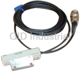
Omron V680-D1KP53M RFID Systems with ISO/IEC 18000-3 (ISO/IEC15693) Compliance
Omron V680-D1KP54T RFID Systems with ISO/IEC 18000-3 (ISO/IEC15693) Compliance
Omron V680-D1KP66MT RFID Systems with ISO/IEC 18000-3 (ISO/IEC15693) Compliance
Omron V680-D1KP66T RFID Systems with ISO/IEC 18000-3 (ISO/IEC15693) Compliance
Request a Quote

The quote request has been received
Close

Facing challenges or have inquiries? Feel free to contact us!
Call Us +1-469-283-2440
What they say about us
FANTASTIC RESOURCE
One of our top priorities is maintaining our business with precision, and we are constantly looking for affiliates that can help us achieve our goal. With the aid of GID Industrial, our obsolete product management has never been more efficient. They have been a great resource to our company, and have quickly become a go-to supplier on our list!
Bucher Emhart Glass
EXCELLENT SERVICE
With our strict fundamentals and high expectations, we were surprised when we came across GID Industrial and their competitive pricing. When we approached them with our issue, they were incredibly confident in being able to provide us with a seamless solution at the best price for us. GID Industrial quickly understood our needs and provided us with excellent service, as well as fully tested product to ensure what we received would be the right fit for our company.
Fuji
HARD TO FIND A BETTER PROVIDER
Our company provides services to aid in the manufacture of technological products, such as semiconductors and flat panel displays, and often searching for distributors of obsolete product we require can waste time and money. Finding GID Industrial proved to be a great asset to our company, with cost effective solutions and superior knowledge on all of their materials, it’d be hard to find a better provider of obsolete or hard to find products.
Applied Materials
CONSISTENTLY DELIVERS QUALITY SOLUTIONS
Over the years, the equipment used in our company becomes discontinued, but they’re still of great use to us and our customers. Once these products are no longer available through the manufacturer, finding a reliable, quick supplier is a necessity, and luckily for us, GID Industrial has provided the most trustworthy, quality solutions to our obsolete component needs.
Nidec Vamco
TERRIFIC RESOURCE
This company has been a terrific help to us (I work for Trican Well Service) in sourcing the Micron Ram Memory we needed for our Siemens computers. Great service! And great pricing! I know when the product is shipping and when it will arrive, all the way through the ordering process.
Trican Well Service
GO TO SOURCE
When I can't find an obsolete part, I first call GID and they'll come up with my parts every time. Great customer service and follow up as well. Scott emails me from time to time to touch base and see if we're having trouble finding something.....which is often with our 25 yr old equipment.
ConAgra Foods