

 Manufacturers
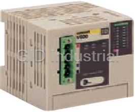
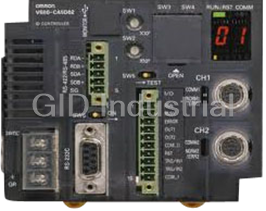
OMRON V600-HAM42-DRT
Description
Omron V600-HAM42-DRT Multi-functional RFID amplifier
Part Number
V600-HAM42-DRT
Price
Request Quote
Manufacturer
OMRON
Lead Time
Request Quote
Category
Amplifier
Features
- Allows data to be written in units of up to 16 bits
- CE marking/FCC approvals
- Conforms to DeviceNet standards
- Responds flexibly to applications with data reading up to 24 bits
- Uses the same main functions (Read, Write, Bit Set, Bit Clear,etc.) as those of the V600-HA Intelligent Flag Series
Datasheet

Extracted Text
V600 RFID System - - V600 HAM42 DRT Intelligent Flag for CompoBus/D Amplifier System Configuration Master Unit Master Unit ( ) CompoBus/D -compatible I/O I/O V600-HAM42-DRT (Amplifier) V600-HS@@ (Sensors) V600-D@@ (Data Carriers) Intelligent Flag III V600-HAM42-DRT An RFID system that is as easy and simple to use as a sensor. No programming required. • Conforms to DeviceNet standards. Uses the same main functions (Read, Write, Bit Set, Bit Clear, etc.) as those of the V600-HA Intelligent Flag Series. Responds flexibly to applications with data reading up to 24 bits. Allows data to be written in units of up to 16 bits. CE marking/FCC approvals. Ordering Information/Specifications ■ Amplifier Item V600-HAM42-DRT Communications power supply 11 to 25 VDC (provided from communications connector) voltage Internal circuit power supply voltage 18 to 26.4 VDC Internal current consumption Communications power supply: 40 mA max. Internal circuit power supply: 150 mA max. Noise immunity Internal circuit power supply normal: ±600 V Internal circuit power supply common: ±1,500 V Dielectric strength 50/60 Hz at 500 V AC for 1 minute; leakage current 10 mA max. Vibration resistance 10 to 55 Hz, 1.5-mm double amplitude, with 4 sweeps of 8 min each in 3 directions 2 Shock resistance 294 m/s , 3 times each in 3 directions (18 times total) Ambient temperature 0 to 55°C (with no icing) Ambient humidity 35% to 85% RH (with no condensation) Storage temperature −25 to 65°C Degree of protection IEC 60529: IP20 (panel mounted) Mounting method DIN track or direct mounting using accessory fittings (M4 screws) Weight Approx. 150 g 2 Intelligent Flag III V600-HAM42-DRT ■ Sensor Model V600-HS51 V600-HS61 V600-HS63 V600-HS67 Shape Item Oscillation frequency 530 kHz Ambient temperature −10 to 60°C −10 to 70°C Storage temperature −25 to 75°C Ambient humidity 35% to 95% Insulation resistance 50 MΩ (at 500 V DC) between cable terminal and case Dielectric strength 1,000 V AC, 50/50 Hz for 1 min between cable terminal and cable (leakage current 1 mA max.) Degree of protection IEC 60529: IP67 Vibration resistance 10 to 2,000 Hz, 3-mm double amplitude, with 2 sweeps 10 to 500 Hz, 2-mm double amplitude, with 3 sweeps of of 15 min each in 3 directions 11 min each in 3 directions 2 2 Shock resistance 981 m/s , 3 times each in 3 directions (18 times total) 490 m/s , 3 times each in 3 directions (18 times total) Cable length 2 m (fixed) Wireless transmission 16-bit CRC (Cyclic Redundancy Check) in both directions error direction Indicator --- Power: green Weight Approx. 70 g Approx. 190 g Approx. 540 g ■ Performance Number of Master words Input: 2; output: 2 (total: 4 words) Number of sensor connections 1 channel Applicable sensors V600-HS51, V600-HS61, V600-HS63, V600-HS67 Read DATA READ mode Read 24 bits of data from the set address Write BYTE mode Write 8-bit or 16-bit data from the set address BIT SET mode Set (write “1”) only the data for the bits that are set (with “1”) at the set address BIT CLEAR mode Clear (write “0”) only the data for the bits that are set (with “1”) at the set address Intelligent Flag III V600-HAM42-DRT 3 Host System Amplifier Sensor Data Carriers System Configuration Programmable Controller Programmable Controller Master Unit Master Unit I/O I/O V600-HAM42-DRT V600-HAM42-DRT V600-HS51 V600-HS61 V600-HS63 V600-HS67 V600 V600 V600 V600 V600 V600 V600 V600 V600 V600 V600 V600 -D23P53 -D23P55 -D23P54 -D23P61 -D23P66N -D23P66SP -D23P72 -D23P71 -D8KR12 -D8KR13 -D8KR04 -D2KR16 4 Intelligent Flag III V600-HAM42-DRT ■ Transmission Distance Specifications Amplifier V600-HAM42-DRT Data Carrier Sensor V600-HS51 V600-HS61 V600-HS63 V600-HS67 Memory V600-D23P53 0.5 to 3.0 mm 0.5 to 3.0 mm --- --- EEP-ROM Type V600-D23P54 0.5 to 5.0 mm 0.5 to 5.5 mm --- --- V600-D23P55 0.5 to 7.0 mm 0.5 to 7.0 mm --- --- V600-D23P61 0.5 to 8.0 mm 0.5 to 9.0 mm 2 to 16 mm --- V600-D23P66N --- --- 5 to 30 mm 5 to 35 mm V600-D23P66SP --- --- 5 to 25 mm 5 to 30 mm V600-D23P71 --- --- 5 to 35 mm 10 to 65 mm V600-D23P72 --- 0.5 to 18 mm 5 to 35 mm 10 to 45 mm Memory V600-D8KR12 5 to 15 mm 5 to 18 mm 5 to 45 mm 10 to 50 mm S-RAM Type V600-D8KR13 --- --- 2 to 15 mm --- V600-D2KR16 --- --- 2 to 15 mm --- V600-D8KR04 --- --- 10 to 65 mm 10 to 90 mm Note: 1. Sensor installation conditions V600-HS51: When flush-mounted in iron Axial offset from the Data Carrier ±2.0 mm V600-HS61: When surface-mounted on metal (ferrous) Axial offset from the Data Carrier: ±2.0 mm V600-HS63: When surface-mounted on metal (ferrous) Axial offset from the Data Carrier: ±10.0 mm V600-HS67: When surface-mounted on metal (ferrous) Axial offset from the Data Carrier: ±10.0 mm 2. Data Carrier installation conditions V600-D23P53/-P54: When flush-mounted in iron V600-D23P55: When flush-mounted in iron, the transmission distance decreases greatly. V600-D23P66N/-P66SP/-P71/-P72: When surface-mounted on resin (no metal on the backside) V600-D23P61: When surface-mounted on metal (ferrous) V600-D8KR12/13/04: When surface-mounted on metal (ferrous) V600-D2KR16: When the Data Carrier attached to the holder is mounted on metal (ferrous) 3. The transmission distance specified in the specifications is also applicable when the Data Carrier is mounted on non-metallic surfaces. 4. The Data Carrier is stationary. Characteristic Data (Typical) ■ Transmission Range Note: All units are in millimeters unless otherwise indicated. Combinations with the V600-HS51 Sensor V600-HS51 & V600-D23P53 V600-HS51 & V600-D23P54 V600-HS51 & V600-D23P55 Y Y Y Y Y Y X 12 15 X X 8 10 8 4 4 5 –8 –4 0 4 8 X –12 –8 –4 0 4 812 X –15 –10 –5 0 5 10 15 X V600-HS51 & V600-D23P61 V600-HS51 & V600-D8KR12 Y Y Y Y 15 30 X X 10 20 5 10 –15 –10 –5 0 5 10 15 X –30 –20 –10 0 10 20 30 X Intelligent Flag III V600-HAM42-DRT 5 Combinations with the V600-HS61 Sensor V600-HS61 & V600-D23P53 V600-HS61 & V600-D23P54 V600-HS61 & V600-D23P55 Y Y Y Y Y Y 15 12 X 8 X X 10 8 4 5 4 –8 –4 0 4 8 X –12 –8 –4 0 4 8 12 X –15 –10 –5 0 5 10 15 X V600-HS61 & V600-D23P61 V600-HS61 & V600-D23P72 V600-HS61 & V600-D8KR12 Y Y Y Y Y Y 30 20 30 X X X 15 20 20 10 10 10 5 –30 –20 –10 0 10 20 30 X –25 –20 –15 –10 –5 0 5 10 15 20 25 X –30 –20 –10 0 10 20 30 X Combinations with the V600-HS63 Sensor V600-HS63 & V600-D23P55 V600-HS63 & V600-D23P61 V600-HS63 & V600-D23P66N Y Y Y Y Y 50 Y 30 30 40 X X X 30 20 20 20 10 10 10 –40 –30 –20 –10 0 10 20 30 40 X –30 –20 –10 0 10 20 30 X –50 –40 –30 –20 –10 0 10 20 30 40 50 X V600-HS63 & V600-D23P66SP V600-HS63 & V600-D23P71 V600-HS63 & V600-D23P72 Y Y Y Y Y Y 50 60 40 60 X X X X 30 40 40 20 20 20 10 –50 –40 –30 –20 –10 0 102030 40 50 X –60 –40 –20 0 204060 X –60 –40 –20 0 20 40 60 X V600-HS63 & V600-D8KR12 V600-HS63 & V600-D8KR13 V600-HS63 & V600-D8KR04 Y Y Y Y Y Y 80 60 60 X X X 60 40 40 40 20 20 20 –80 –60 –40 –20 0 20406080 X –60 –40 –20 0 20 40 60 X −60 −40 −20 0 20 40 60 X V600-HS63 & V600-D2KR16 Y Y 60 X 40 20 –80 –60 –40 –20 0 20 40 60 80X 6 Intelligent Flag III V600-HAM42-DRT Combinations with the V600-HS67 Sensor V600-HS67 & V600-D23P66N V600-HS67 & V600-D23P66SP V600-HS67 & V600-D23P71 Y Y Y Y Y Y 80 80 100 80 60 60 X X X X 60 40 40 40 20 20 20 –80 –60 –40 –20 020 40 60 80 X –80 –60 –40 –20 0 20 40 60 80 X –100 –80 –60 –40 –20 0 20 40 60 80 100 X V600-HS67 & V600-D23P72 V600-HS67 & V600-D8KR12 V600-HS67 & V600-D8KR13 Y Y Y Y Y Y 100 80 80 80 X X 60 60 X 60 40 40 40 20 20 20 –80 –60 –40 –20 0 20406080 X –100 –80 –60 –40 –20 0 20 40 60 80 100X –80 –60 –40 –20 0 20406080 X V600-HS67 & V600-D8KR04 Y Y 120 X 80 40 –120 –80 –40 0 40 80 120 X ■ Transmission Time The transmission time is the time required for transmission between the Sensor and the Data Carrier. Model V600-HAM42-DRT Read Write Mode type DATA READ mode BYTE mode BIT SET mode, BIT CLEAR mode Data Carrier type Battery-less type 79 ms 140 ms 152 ms Built-in battery type 64 ms 97 ms 109 ms Battery-less type: V600-D23P53, V600-D23P54, V600-D23P55, V600-D23P61, V600-D23P66N, V600-D23P66SP, V600-D23P72, V600- D23P71, V600-D23P72 Built-in battery type: V600-D8KR12, V600-D8KR13, V600-D8KR04, V600-D2KR16 Intelligent Flag III V600-HAM42-DRT 7 Dimensions Note: All units are in millimeters unless otherwise indicated. Amplifier V600-HAM42-DRT 65 50.85 Mounting bracket 5.5 8 23.1 4.9 7.3 66 55 2.2X7=15.4 35.2 35 2.2 65 16.7 48.6 42.5 38.85 Two, 4.5-dia. mounting holes 4 Mounting Hole Dimensions Communications 3-way operating 16-way operating connector indicator indicator 2-M4 Three terminals Sensor connector 7.6 7.6 40.3 55±0.2 3 60 48 23.3 24.1 Sensor V600-HS51 2 lock washers Vinyl-insulated round cord (4-mm dia.) 2 lock nuts M12X1 Connector 13.7 dia. 9.6 dia. 7 49.5 33 35 V600-HS61 30.5 18 4.5 ± 8.5 12 0.2 49.5 18 13.7 dia. Connector Detection surface 2-3.5X5 Vinyl-insulated round cord (4-mm dia.) (mounting holes) 10 6.5 8 Intelligent Flag III V600-HAM42-DRT V600-HS63 Two, 4.5-dia. mounting holes 4-R1 2-R5 Vinyl-insulated round cord 6-mm dia Connector (7/0.18-mm dia.), 8-conductor cable, Bushing 10 standard length: 2 m 40 28 13.8 dia. 51.5 5 5 13 5 27 6 53 20 18 Power indicator (green) 23 11 V600-HS67 Four, 4.5-dia. 100 mounting holes ±0.2 5 90 5 50 50 Connector Power indicator 25 (green) 100 13.8 dia. ±0.2 90 51.5 Bushing Vinyl-insulated round cord (6-mm dia.) 10 14 10 30 20 11 V600-series Data Carrier Built-in-battery DCs V600-D8KR12 V600-D8KR04 65 86 0.2 5 55± Two, 4.5-dia. mounting holes 31 27 10 Four, 4.5-dia. mounting holes 5 76±0.2 5 10 40 30±0.2 0.2 54 44± Case: ABS resin 15 8 Filler: Epoxy resin Case: ABS resin 20 Filler: Epoxy resin 10 Intelligent Flag III V600-HAM42-DRT 9 V600-D8KR13 Replaceable-battery DCs 86 V600-D2KR16 Two, 4.5-dia. mounting holes 27 10 4-R1.5 10 65 54 44±0.2 40 76±0.2 R0.5 5 Case: ABS resin Case: ABS resin 10.3 5 Filler: Epoxy resin 5 Battery-less DCs V600-D23P53 V600-D23P54 V600-D23P55 V600-D23P61 36 0.1 30± 24 0 R0.3 12 dia. – 0.2 0 R0.2 R0.2 0 8 dia. 8 dia. – 0.1 – 0.1 24 2-R1.0 0 Two, 3.5-dia. mounting holes 0 5 5 – 0.1 – 0.1 0 6 – 0.2 6 2.2 Case: ABS resin Case: ABS resin Case: PPS resin Case: ABS resin Filler: Epoxy resin Filler: Epoxy resin Filler: Epoxy resin Filler: Epoxy resin V600-D23P66N V600-D23P72 Mounting Hole Dimensions 4-R2 50 4-R4 0.2 25± 4-R3 2-M3 34 25±0.2 0.2 34 32 25± Two, 3.5-dia. Case: Glass epoxy resin Two, 6-dia. Coating: Polyurethane resin 1.5 0.2 25± 32 3.5±0.1 34 Case: PPS resin V600-D23P66SP Two, 5.5-dia. 4-R6 34 Mounting Hole Dimensions mounting holes 2-M5 36.5 34 0.2 80± Coating: PFA resin 6.5 1.3 80±0.2 2.5 max. 95 V600-D23P71 4-R2 86 54 Case: Glass epoxy resin Coating: Polyurethane resin 1.5 ALL DIMENSIONS SHOWN ARE IN MILLIMETERS. To convert millimeters into inches, multiply by 0.03937. To convert grams into ounces, multiply by 0.03527. 10 Intelligent Flag III V600-HAM42-DRT Intelligent Flag III V600-HAM42-DRT 11 READ AND UNDERSTAND THIS DOCUMENT Please read and understand this document before using the products. Please consult your OMRON representative if you have any questions or comments. WARRANTY OMRON’s exclusive warranty is that the products are free from defects in materials and workmanship for a period of one year (or other period if specified) from date of sale by OMRON. OMRON MAKES NO WARRANTY OR REPRESENTATION, EXPRESS OR IMPLIED, REGARDING NON-INFRINGEMENT, MERCHANTABILITY, OR FITNESS FOR PARTICULAR PURPOSE OF THE PRODUCTS. ANY BUYER OR USER ACKNOWLEDGES THAT THE BUYER OR USER ALONE HAS DETERMINED THAT THE PRODUCTS WILL SUITABLY MEET THE REQUIREMENTS OF THEIR INTENDED USE. OMRON DISCLAIMS ALL OTHER WARRANTIES, EXPRESS OR IMPLIED. LIMITATIONS OF LIABILITY OMRON SHALL NOT BE RESPONSIBLE FOR SPECIAL, INDIRECT, OR CONSEQUENTIAL DAMAGES, LOSS OF PROFITS OR COMMERCIAL LOSS IN ANY WAY CONNECTED WITH THE PRODUCTS, WHETHER SUCH CLAIM IS BASED ON CONTRACT, WARRANTY, NEGLIGENCE, OR STRICT LIABILITY. In no event shall responsibility of OMRON for any act exceed the individual price of the product on which liability is asserted. IN NO EVENT SHALL OMRON BE RESPONSIBLE FOR WARRANTY, REPAIR, OR OTHER CLAIMS REGARDING THE PRODUCTS UNLESS OMRON’S ANALYSIS CONFIRMS THAT THE PRODUCTS WERE PROPERLY HANDLED, STORED, INSTALLED, AND MAINTAINED AND NOT SUBJECT TO CONTAMINATION, ABUSE, MISUSE, OR INAPPROPRIATE MODIFICATION OR REPAIR. SUITABILITY FOR USE THE PRODUCTS CONTAINED IN THIS DOCUMENT ARE NOT SAFETY RATED. THEY ARE NOT DESIGNED OR RATED FOR ENSURING SAFETY OF PERSONS, AND SHOULD NOT BE RELIED UPON AS A SAFETY COMPONENT OR PROTECTIVE DEVICE FOR SUCH PURPOSES. Please refer to separate catalogs for OMRON's safety rated products. OMRON shall not be responsible for conformity with any standards, codes, or regulations that apply to the combination of products in the customer’s application or use of the product. At the customer’s request, OMRON will provide applicable third party certification documents identifying ratings and limitations of use that apply to the products. This information by itself is not sufficient for a complete determination of the suitability of the products in combination with the end product, machine, system, or other application or use. The following are some examples of applications for which particular attention must be given. This is not intended to be an exhaustive list of all possible uses of the products, nor is it intended to imply that the uses listed may be suitable for the products: • Outdoor use, uses involving potential chemical contamination or electrical interference, or conditions or uses not described in this document. • Nuclear energy control systems, combustion systems, railroad systems, aviation systems, medical equipment, amusement machines, vehicles, safety equipment, and installations subject to separate industry or government regulations. • Systems, machines, and equipment that could present a risk to life or property. Please know and observe all prohibitions of use applicable to the products. NEVER USE THE PRODUCTS FOR AN APPLICATION INVOLVING SERIOUS RISK TO LIFE OR PROPERTY WITHOUT ENSURING THAT THE SYSTEM AS A WHOLE HAS BEEN DESIGNED TO ADDRESS THE RISKS, AND THAT THE OMRON PRODUCT IS PROPERLY RATED AND INSTALLED FOR THE INTENDED USE WITHIN THE OVERALL EQUIPMENT OR SYSTEM. PERFORMANCE DATA Performance data given in this document is provided as a guide for the user in determining suitability and does not constitute a warranty. It may represent the result of OMRON’s test conditions, and the users must correlate it to actual application requirements. Actual performance is subject to the OMRON Warranty and Limitations of Liability. CHANGE IN SPECIFICATIONS Product specifications and accessories may be changed at any time based on improvements and other reasons. It is our practice to change model numbers when published ratings or features are changed, or when significant construction changes are made. However, some specifications of the product may be changed without any notice. When in doubt, special model numbers may be assigned to fix or establish key specifications for your application on your request. Please consult with your OMRON representative at any time to confirm actual specifications of purchased products. DIMENSIONS AND WEIGHTS Dimensions and weights are nominal and are not to be used for manufacturing purposes, even when tolerances are shown. ERRORS AND OMISSIONS The information in this document has been carefully checked and is believed to be accurate; however, no responsibility is assumed for clerical, typographical, or proofreading errors, or omissions. PROGRAMMABLE PRODUCTS OMRON shall not be responsible for the user’s programming of a programmable product, or any consequence thereof. COPYRIGHT AND COPY PERMISSION This document shall not be copied for sales or promotions without permission. This document is protected by copyright and is intended solely for use in conjunction with the product. Please notify us before copying or reproducing this document in any manner, for any other purpose. If copying or transmitting this document to another, please copy or transmit it in its entirety. Cat. No. Q115-E1-02 In the interest of product improvement, specifications are subject to change without notice. OMRON Corporation Industrial Automation Company Application Sensors Division Sensing Devices and Components Division H.Q. Shiokoji Horikawa, Shimogyo-ku, Printed in Japan Kyoto, 600-8530 Japan 1004 (0203) Tel: (81)75-344-7068/Fax: (81)75-344-7107
Frequently asked questions
How does Industrial Trading differ from its competitors?

Is there a warranty for the V600-HAM42-DRT?
Which carrier will Industrial Trading use to ship my parts?
Can I buy parts from Industrial Trading if I am outside the USA?
Which payment methods does Industrial Trading accept?


What they say about us
FANTASTIC RESOURCE
One of our top priorities is maintaining our business with precision, and we are constantly looking for affiliates that can help us achieve our goal. With the aid of GID Industrial, our obsolete product management has never been more efficient. They have been a great resource to our company, and have quickly become a go-to supplier on our list!
Bucher Emhart Glass
EXCELLENT SERVICE
With our strict fundamentals and high expectations, we were surprised when we came across GID Industrial and their competitive pricing. When we approached them with our issue, they were incredibly confident in being able to provide us with a seamless solution at the best price for us. GID Industrial quickly understood our needs and provided us with excellent service, as well as fully tested product to ensure what we received would be the right fit for our company.
Fuji
HARD TO FIND A BETTER PROVIDER
Our company provides services to aid in the manufacture of technological products, such as semiconductors and flat panel displays, and often searching for distributors of obsolete product we require can waste time and money. Finding GID Industrial proved to be a great asset to our company, with cost effective solutions and superior knowledge on all of their materials, it’d be hard to find a better provider of obsolete or hard to find products.
Applied Materials
CONSISTENTLY DELIVERS QUALITY SOLUTIONS
Over the years, the equipment used in our company becomes discontinued, but they’re still of great use to us and our customers. Once these products are no longer available through the manufacturer, finding a reliable, quick supplier is a necessity, and luckily for us, GID Industrial has provided the most trustworthy, quality solutions to our obsolete component needs.
Nidec Vamco
TERRIFIC RESOURCE
This company has been a terrific help to us (I work for Trican Well Service) in sourcing the Micron Ram Memory we needed for our Siemens computers. Great service! And great pricing! I know when the product is shipping and when it will arrive, all the way through the ordering process.
Trican Well Service
GO TO SOURCE
When I can't find an obsolete part, I first call GID and they'll come up with my parts every time. Great customer service and follow up as well. Scott emails me from time to time to touch base and see if we're having trouble finding something.....which is often with our 25 yr old equipment.
ConAgra Foods