

 Manufacturers
OMRON H8GN

Description
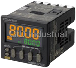
Omron H8GN Counter/Timer Modules-Preset Counter/Timer (48 × 24)
Part Number
H8GN
Price
Request Quote
Manufacturer
OMRON
Lead Time
Request Quote
Category
Counter/Timer Modules
Specifications
Attachment
Waterproof packing, flush mounting bracket
Digits
4 Digits
Display
7-segment, negative transmissive LCD
External connections
Screw terminals (M3 screws)
Maximum counting speed
30 Hz or 5 kHz
Mounting method
Flush mounting
Operating voltage range
85% to 110% of rated supply voltage
Power consumption
1.5 W max. (for max. DC load) (Inrush current: 15 A max.)
Terminal screw tightening torque
0.5 N·m max.
Timer modes
Elapsed time (Up), remaining time (Down)
Features
- Built-in prescaling for counter operation.
- ON/OFF-duty adjustable flicker mode that can be used to perform cyclic control is available for timer operation.
- Only 48 × 24 × 83 mm (W × H × D)
- SV can be changed using front panel keys to any of four values preset in SV-banks.
- Switch between 4-digit preset counter and 4-digit timer operation.
- Water-proof structure to NEMA4X/IP66.
- While using the preset counter, it is possible to switch the display to monitor the totalizing count value (8 digits).
Datasheet

Extracted Text
Preset Counter/Timer (48 × 24) H8GN CSM_H8GN_DS_E_3_1 A DIN 48 × 24 Preset Counter. Compact, Yet Equipped with Communication. • Only 48 × 24 × 83 mm (W × H × D) Switch between 4-digit preset counter and 4-digit timer opera- tion. While using the preset counter, it is possible to switch the dis- play to monitor the totalizing count value (8 digits). Built-in prescaling for counter operation. ON/OFF-duty adjustable flicker mode that can be used to per- form cyclic control is available for timer operation. SV can be changed using front panel keys to any of four values preset in SV-banks. Water-proof structure to NEMA4X/IP66. Conforms to UL, CSA, and IEC safety standards as well as CE Marking. Refer to Safety Precautions on page 7. Model Number Structure ■ Model Number Legend H8GN-AD-@ 1 2 1. Supply Voltage 2. Communications Output Type D: 24 VDC None: Communications not supported FLK: RS-485 Ordering Information ■ List of Models Supply voltage Output Communications No communications RS-485 24 VDC Contact output (SPDT) H8GN-AD H8GN-AD-FLK 1 H8GN Specifications ■ Ratings Rated supply voltage 24 VDC Operating voltage range 85% to 110% of rated supply voltage Power consumption 1.5 W max. (for max. DC load) (Inrush current: 15 A max.) Mounting method Flush mounting External connections Screw terminals (M3 screws) Terminal screw tightening torque 0.5 N⋅m max. Attachment Waterproof packing, flush mounting bracket Display 7-segment, negative transmissive LCD; time display (h, min, s); CMW, OUT, RST, TOTAL Present value (red, 7-mm-high characters); Set value (green, 3.4-mm-high characters) Digits PV: 4 digits SV: 4 digits When total count value is displayed: 8 digits (Zeros suppressed) Memory backup EEPROM (non-volatile memory) (number of writes: 100,000 times) Counter Maximum counting speed 30 Hz or 5 kHz (See note.) Counting range −999 to 9,999 Input modes Increment, decrement, individual, quadrature inputs Output modes N, F, C, or K Timer Time ranges 0.000 to 9.999 s, 0.00 to 99.99 s, 0.0 to 999.9 s, 0 to 9999 s, 0 min 00 s to 99 min 59 s, 0.0 to 999.9 min, 0 h 00 min to 99 h 59 min, 0.0 h to 999.9 h, 0 h to 9999 h Timer modes Elapsed time (Up), remaining time (Down) Output modes A, B, D, E, F, or Z Inputs Input signals For Counter: CP1, CP2, and reset For Timer: Start, gate, and reset Input method No-voltage input (contact short-circuit and open input) Short-circuit (ON) impedance: 1 kΩ max. (Approx. 2 mA runoff current at 0 Ω) Short-circuit (ON) residual voltage:2 VDC max. Open (OFF) impedance: 100 kΩ min. Applied voltage: 30 VDC max. Start, reset, gate Minimum input signal width: 1 or 20 ms (selectable) Power reset Minimum power-opening time: 0.5 s Control output SPDT contact output: 3 A at 250 VAC/30 VDC, resistive load (cosφ = 1) Minimum applied load 10 mA at 5 VDC (failure level: P, reference value) Reset system External, manual, and power supply resets (for timer in A, B, D, E, or Z modes) Sensor waiting time 260 ms max. (Inputs cannot be received during sensor wait time if control outputs are turned OFF.) Note: The figures given for maximum counting speed are for incrementing or decrementing operation with a prescale value of ×1. If prescaling is used and 5 kHz is set, the maximum counting speed will be reduced to about half. The maximum counting speed will also be reduced to about half when the up/down mode is selected. 2 H8GN ■ Characteristics Timer function Accuracy of operating Signal start: ± 0.03% ± 30 ms max. time and setting error Power-ON start: ± 0.03% ± 50 ms max. (including temperature and voltage effects) Insulation resistance 100 MΩ min. (at 500 VDC) Dielectric strength 1,500 VAC, 50/60 Hz for 1 min between output terminals and non-current-carrying metal parts 510 VAC, 50/60 Hz for 1 min between current-carrying terminals (except output terminals) and non-current-carrying metal parts 1,500 VAC, 50/60 Hz for 1 min between output terminals and current-carrying terminals (ex- cept output terminals) 500 VAC, 50/60 Hz for 1 min between communications terminals and current-carrying termi- nals (except output terminals) 1,000 VAC, 50/60 Hz for 1 min between contacts not located next to each other Noise immunity Square-wave noise by noise simulator; ±480 V (between power terminals), ± 600 V (between input terminals) Static immunity ± 8 kV (malfunction), ± 15 kV (destruction) Vibration resistance Malfunction 10 to 55 Hz with 0.35-mm single amplitude each in three directions for 10 min Destruction 10 to 55 Hz with 0.75-mm single amplitude each in three directions for 2 h 2 Shock resistance Malfunction 100 m/s , 3 times each in six directions 2 Destruction 300 m/s , 3 times each in six directions Life expectancy Mechanical 10 million operations Electrical 100,000 operations min. (3 A at 250 VAC, resistive load) (See note.) Ambient temperature Operating −10°C to 55°C (with no icing or condensation) Storage −25°C to 65°C (with no icing or condensation) Ambient humidity 25% to 85% EMC (EMI): EN61326 Emission Enclosure: EN55011 Group 1 Class A (EMS): EN61326 Immunity ESD: EN61000-4-2: 4 kV contact discharge (level 2) 8 kV air discharge (level 3) Immunity RF-interference: EN61000-4-3: 10 V/m (Amplitude-modulated, 80 MHz to 1 GHz) (level 3); 10 V/m (Pulse-modulated, 900 MHz ± 5 MHz) (level 3) Immunity Conducted Disturbance: EN61000-4-6: 3 V (0.15 to 80 MHz) (level 2) Immunity Burst: EN61000-4-4: 2 kV power-line (level 3); 1 kV I/O signal-line (level 4); 1 kV communications-line (level 3) Immunity Surge: EN61000-4-5: 1 kV between lines (power and output lines) (level 3); 2 kV between grounds (power and output lines) (level 3) Approved standards UL508, CSA C22.2 No.14 Conforms to EN61010-1/IEC61010-1 (Pollution degree 2/overvoltage category II) Conforms to VDE0106/P 100 (Finger Protection) Case color Rear section: Gray smoke; Front section: N1.5 (black) Degree of protection Panel surface: IP66 and NEMA Type 4X (indoors) Rear case: IP20 Terminal block: IP20 Weight Approx. 80 g Note: Refer to the Life-test Curve. 3 H8GN ■ Communications Specifications Transmission path connections Multidrop Communications method RS-485 (two-wire, half duplex) Synchronization method Start-stop synchronization Baud rate (See note.) 1,200/2,400/4,800/9,600 bit/s Transmission code ASCII Data bit length (See note.) 7 or 8 bits Stop bit length (See note.) 1 or 2 bits Error detection Vertical parity (none, even, or odd) (See note.) Block check character (BCC) Flow control Not supported. Interface RS-485 Retry function Not supported. Communications buffer 40 bytes Reading and writing from H8GN Reading present value and totalizing count value; reading/writing preset and set values; switching be- tween SV-banks; switching between communications write-enabled/write-prohibited; reading/writing other initial and advanced function setting parameters Note: The baud rate, data bit length, stop bit length, and vertical parity can be individually set using the communications setting level. ■ Life-test Curve (Reference Values) Resistive Load Reference: A maximum current of 0.15 A can be switched at 1,000 125 VDC (cosφ = 1) and a maximum current of 0.1 A can be switched if L/R is 7 ms. In both cases, a life of 700 100,000 operations can be expected. The minimum 500 applicable load is 10 mA at 5 VDC (failure level: P). 300 30 VDC (cosφ = 1) 250 VAC (cosφ = 1) 100 70 50 01 2 3 4 Load current (A) 4 3 Switching operations (×10 ) H8GN Connections ■ Block Diagram Communications (Basic Output circuit insulation) circuit (Functional (Basic insulation) insulation) Display circuit Internal Input circuit control circuit Key switch circuit Power supply circuit ■ I/O Functions Inputs Counter inputs CP1/CP2 • Receive count signals. Receive increment, decrement, individual, and quadrature inputs. In increment mode and decrement mode, CP1 is used for the count input and CP2 is used for count prohibit input. Reset Resets the present value. (Totalizing count value is not reset.) (In increment mode or increment/decrement mode, the present value returns to 0; in Decre- ment Mode the present value returns to the set value.) The count input is not received during resetting. The RST indicator is lit during resetting. Timer inputs Start Starts timing. Reset Resets the timer. (In elapsed time mode the time returns to 0; in remaining time mode, the time returns to the set value.) During resetting, timing stops and the control output turns OFF. The RST indicator is lit during resetting. Gate Prohibits timing operation. Outputs OUT Output made according to the output mode setting when the set value is reached. ■ Terminal Arrangement ■ Wiring Communications* Use the following type of crimp terminals for M3 screw. *Only models with communications RS-485 Not Output connected 5.8 mm max. CP1/ CP2/ Reset 5.8 mm max. Start Gate 24-VDC power supply Contact inputs Open-collector inputs Note: (2) and (6) are connected internally. Do not use unused terminals as relay terminals. 5 H8GN Nomenclature No. 1 Display Operation display 2 Displays the present value or parameter type. Indicator Meaning When totalizing count is displayed, the leftmost 4 digits of the 8-digit totalizing count CMW Lit when communications writing is enabled. will be displayed. (Zeros suppressed) RST Lit during reset using reset input or Reset Key. OUT Lit when control output is ON. TOTAL Lit when totalizing count value is displayed. Operation display 1 Displays the time unit when the No. 2 Display timer function has been selected. Displays set value or Example set value of the parameter. 5 h 30 min Displays the rightmost 4 digits of 123.4 s the count value (8 digits) when the H8GN is used as a Flashes while timer is on 0.0 min, totalizing counter. 0 h 00 min, 0.0 h, or 0 h. (Zeros suppressed) Level Key Mode Key Down Key Up/Reset Key Press this key to select the setup Press this key to select Each press of this key decreases Each press of this key level. The setup level is selected in parameters within each values displayed on the No. 2 increases values order "operation level" ←→ level. display. Hold down this key displayed on the No. 2 "adjustment level", "initial setting continuously to decrease values display. Hold down this level" ←→ "communications setting quickly. Also returns setting key continuously to level". items. increase values quickly. Also advances setting items. Reset Function To reset the present value, press this key while the present value is displayed. If this key is pressed while the totalizing count value is displayed, the totalizing count value and the present value will be reset. 6 H8GN Dimensions Note: All units are in millimeters unless otherwise indicated. Panel cutout H8GN M3 terminal screw Separate Gang mounting mounting (48 × No. of units +1.0 − 2.5) 0 40 min. The product cannot be made waterproof when gang-mounted. • Insert the H8GN in the square cutout, insert the adapter from the back, and push the H8GN into the cutout as far as possible. Use screws to secure the H8GN. To make the H8GN waterproof, insert waterproof packing and tighten the screws. No. 1 display digit size No. 2 display digit size 3.4 mm • When mounting two or more products 7 mm in a cutout, be sure that the ambient temperature does not exceed the 1.6 mm specifications. 3.3 mm Safety Precautions Refer to Safety Precautions for All Counters. Application Precautions !CAUTION 1. Do not use the product in locations where condensation may Tighten the terminal screws to the specified torque (approx. 0.5 N⋅m). occur due to high humidity or where temperature changes are Fire or malfunction may result if the screws become loose. severe. Do not use the product in locations subject to flammable or explosive 2. Be sure to wire terminals correctly, with the correct polarity. gases. Doing so may result in explosion. 3. Maintain the power supply voltage within the allowable ranges. The service life of the output relays depends on the switching capacity 4. Connect the power supply through a relay or switch so that the and switching conditions. Consider the actual application conditions voltage reaches a fixed value immediately. If the voltage and use the product within the rated load and electrical service life. increases gradually the power supply may be reset or outputs Using the product beyond its service life may result in contact may turn ON. deposition or burning. 5. When the power is turned ON, an inrush current (approx. 15 A) Do not disassemble, repair, or modify the product. Doing so may will flow momentarily. Depending on power supply capacities, the result in electric shock, fire, or malfunction. product may not start due to this leakage current. The power sup- ply must be of a sufficiently large capacity. Do not allow metal objects or conductive wires to enter the product. 6. For the main power supply or the power supply for input devices, Doing so may result in electric shock, fire, or malfunction. use a power supply transformer whose primary side is insulated from the secondary side and whose secondary side is not grounded. Other Precautions 7. Leaving the H8GN with outputs ON at a high temperature for a Store at the specified temperature. If the H8GN has been stored at long time may hasten the degradation of internal parts (such as a temperature of less than −10°C, allow the H8GN to stand at room electrolytic capacitors). Therefore, use the product in combination temperature for at least 3 hours before use. with relays and avoid leaving the product as long as more than 1 Use the product within the ratings specified for vibration, shock, month with the output turned ON. submerging in water, and exposure to oil. Do not use the product in locations subject to dust, corrosive gases, or direct sunlight. Use the product within the ratings specified for temperature and humidity. The product is designed for 24 VDC. Applying voltages other than the rated one such as 100 to 240 VAC may damage the internal elements. Separate the input signal devices, input signal cables, and the product from the source of noise or high-tension cables producing noise. Separate the product from the source of static electricity when using the product in an environment where a large amount of static electricity is produced (e.g., forming compounds, powders, or fluid materials being transported by pipe). Do not expose the product to organic solvent such as thinner or benzine, strong alkali materials, or strong acid materials. Doing so may damage the product surface. 7 H8GN Power Supplies Response Delay Time When Resetting When turning the power ON and OFF, input signal reception is possi- The following table shows the delay from when the reset signal is ble, unstable, or impossible as shown in the diagram below. input until the output is turned OFF. Minimum reset signal width Output delay time ON Power OFF supply 1 ms 3.7 to 6.0 ms 210 ms 0 to 50 ms 0 to 500 ms 5 ms 20 ms 19 to 21 ms Input Impossible Possible Unstable Impossible Output Delay Time Unstable Turn the power ON and OFF using a relay with a rated capacity of The following table shows the delay from when the timer value 15 A minimum to prevent contact deterioration due to inrush current passes the set value until the output is produced. caused by turning the power ON and OFF. Actual Measurements in N or K Mode When power is turned ON, a starting current flows momentarily. Therefore, pay attention to the overcurrent detection level of the Control output Max. counting Output delay time* speed power supply used. Contact output 30 Hz 17.3 to 18.9 ms Timer Control with Power Start 5 kHz 3.5 to 5.2 ms To allow for the startup time of peripheral devices (sensors, etc.), the *The variation in delays is due to different modes and conditions. H8GN starts timing operation between 210 to 260 ms after power is turned ON (see diagram above). For this reason, in operations where Mounting timing starts from power ON, the time display will actually start from 258 ms. If the set value is 258 ms or less, the time until output turns Tighten the two mounting screws on the Adaptor. Tighten them alter- ON will be a fixed value between 210 and 260. (Normal operation is nately, a little at a time, so as to keep them at an equal tightness. possible for set value of 259 ms or more.) In applications where a set value of 258 ms or less is required, use start timing with signal input. Adaptor When the H8GN is used with power start in F mode (i.e., accumula- Waterproof packing tive operation with output on hold), there will be a timer error (approx- imately 100 ms each time the H8GN is turned ON) due to the characteristics of the internal circuitry. Use the H8GN with signal Panel start if timer accuracy is required. Using the Prescale Function The count will become incorrect if the prescale value is not set correctly. Check the setting to be sure it is correct. Changing the Set Value The H8GN’s panel surface is water-resistive (conforming to NEMA 4X (indoors) and IP66). In order to prevent the internal circuit from water penetration through the space between the Counter and oper- In Counter Operation ating panel, attach a rubber packing (provided with the H8GN) When changing the set value during operation, the output will turn between the Counter and operating panel and secure the rubber ON if the set value equals the present value. packing with the Flush-mounting Adaptor. In Timer Operation When changing the set value during operation, if the set value is changed in so that the conditions below are satisfied, the Timer oper- ates in the same way as when the present value reaches the set Output value because a constant read-in system is in use. Depending on the output mode, this may result in output turning ON. The SPDT (single-pole, double-throw) consists of an SPST-NO con- tact and an SPST-NC contact. Do not form a circuit with 3-point Timer mode UP: Present value ≥ set value short-circuit (power short-circuiting with arc). Timer mode DOWN:Elapsed time ≥ set value (Present value = 0) Note: When in DOWN mode, the amount set value is changed is add- ed to or subtracted from the present value. Short-circuit current Power supply Operation with a Set value of 0 In Counter Operation The output will turn ON if the set value (0) equals the present value. The output will be OFF while the Reset Key is pressed or the reset input is ON. In Timer Operation a) When the output mode is set to A, B (one-shot output), D, or F, Reference output will turn ON when the start signal is input. b) When the output mode is set to B (hold output), E, or Z, output will For details about communications functions, refer to H8GN Preset remain OFF even when the start signal is input. Counter/Timer User’s Manual (Cat. No. M066). 8 H8GN Operating Procedures ■ Initial Setup The and Keys are used to switch between setup menus, and the amount of time that you hold the keys down for determines which setup menu you move to. This section describes two typical examples. Note: In the following sections, “PV” is used to indicate a present value and “SV” to indicate a set value. 1. Using the H8GN as a Counter Typical Application Examples • Setup Procedure Power ON Power ON 1. Changing Set Values Operation Level Set value and selections in each display can be changed by pressing the and Keys. Present value (PV)/ set value (SV) 2. Displays Press the Level Key for at least 3 s. Operation stops. No. 1 display No. 2 display Initial Setting Level Check Counter/Timer Check Counter/ Function: selection Timer selection Set input mode Use the and Typical Application Input mode: Keys to set the input mode to individual mode. Input mode Individual input Set output mode Use the and Output mode: Output mode F (overcount) Keys to set the output mode to F. Counting speed 30 Hz Check the counting speed. Check counting Counting speed: Input signal width 20 ms speed Decimal point None Check the input signal width. Check input Input signal width: Prescale None signal width Press the Level Key for at least 1 s. Operation starts. Operation Level Set SV Press the and PV/SV: Keys to change the set value to 100. PV: Reset PV Press the Key. Start operation Operate • Confirming Set Values Set values are effective two seconds after key operation is stopped or when the or Key is pressed. 9 H8GN 2. Using the H8GN as a Timer Typical Application Examples • Setup Procedure Power ON Power ON 1. Changing Set Values Operation Level Set value and selections in each display can be changed by pressing the and Keys. Present value (PV)/ set value (SV) 2. Display Press the Level Key for at least 3 s. Operation stops. No. 1 Display No. 2 Display Initial Setting Level Set Counter/Timer Use the and Function: selection Keys to select the timer function. Typical Application Examples Set time range Use the and Time range: Keys to set the time range to 999.9 s Time range 0.0 to 999.9 s Check timer mode Use the and Timer mode DOWN (remaining time) Timer mode: Keys to set the timer mode to remaining time. Output mode A mode Check the output mode. Check output mode Output mode: Output time Hold Input signal width 20 ms Check output time Check the output time. Output time: Check input signal Check the input signal width. Input signal width: width Press the Level Key for at least 1 s. Operation starts. Operation Level Use the and PV/SV: Set SV Keys to set the SV to 10.0. PV: Press the Key. Reset PV Operate Start operation • Confirming Set Values Set values are effective two seconds after key operation is stopped or when the or Key is pressed. 10 H8GN ■ Setting Specifications after Turning ON Power Outline of Operation Procedure Key Operation In the following descriptions, all the parameters are introduced in the display sequence. Some parameters may not be displayed depending on the protection settings and operating conditions. Power ON + Key 3 s. min. (default value) Adjustment level Operation level Protect level Key + less than 1 s. Keys 1 s. min. Key Key Operation stops 1 s. min. 3 s min. Communications Initial setting level setting level Key less than 1 s. Operation in progress Key Password input set value "−169" Operation stopped 1 s. min. Not displayed depending on model and settings. Not displayed depending on model and settings. Advanced function Level change setting level Note: Of these levels, the initial setting level, communications setting level, and advanced function setting level can be used only when operation has stopped. Control output is stopped when these three levels are selected. When switched back to the operation level from one of these levels, operation will start. Description of Each Level Operation Level Protect Level This level is displayed when you turn the power ON. You can move To select this level, simultaneously press the and Keys to the protect level, initial setting level, and adjustment level from for at least three seconds (default value). This level is to prevent this level. unwanted or accidental modification of parameters. Protected lev- Normally, select this level during operation. els will not be displayed, and so the parameters in that level cannot During operation, the present value, set value, totalizing count be modified. value, and setting number of SV-bank can be monitored using the Communications Setting Level Key. To select this level, press the Key once for less than one sec- Adjustment Level ond in the initial setting level. When the communications function is used, set the communications conditions in this level. Communicat- To select this level, press the Key once for less than one sec- ing with a personal computer (host computer) allows set values to ond. be read and written. This level is for entering set value (SV 0 to 3) for operation. This level contains parameters for communications writing enable/dis- Advanced Function Setting Level able, set value of SV-bank, and cycle time (timer Z mode). To select this level, you must change the initial settings/communica- You can move to the top parameter of the operation level, protect tions protection setting in the protect level to “0” and then enter the level, or initial setting level from here. password (“−169”) in the initial setting level. This level is for initializing settings, enabling SV-bank and totalizing Initial Setting Level counter use, setting display auto-return time, and move- to-protect- level time. To select this level, press the Key for at least three seconds in the operation level or adjustment level. You can move to the initial setting level from this level. This level is for selecting the function, input mode, time range, timer mode, output mode, output time, counting speed, input signal width, decimal point position, prescale value, and rising/falling edge for input signal. You can move to the advanced function setting level or communica- tions setting level from this initial setting level. To return to the oper- ation level, press the Key for at least one second. To move to the communications setting level, press the key once for less than one second. 11 H8GN Parameters Operation Level Adjustment Level (1) PV/SV (1) Communications writing control (2) PV (2) SV 0 (3) Totalizing count value (2) SV 1 (4) SV-bank (2) SV 2 1. PV/SV This display appears when the power is turned ON. No. 1 display (2) SV 3 shows the present value and No. 2 display shows the set value. The values displayed will be determined by the settings for Counter/Timer selection, time range, timer mode, and decimal (3) Cycle time point position made in the initial setting level. Use the and Keys to change the settings. 1. Communications Writing Control (cmwt) Communications writing control is displayed only for models 2. PV with communications. No. 1 display will show the present value and No. 2 display will Allows or prohibits communications to write data from a personal remain blank. The values displayed will be determined by the set- computer (host computer). Communications can be used to read tings for Counter/Timer selection, time range, timer mode, and data regardless of this setting. decimal point position made in the initial setting level. 2. SV 0 to 3 (sp-0, sp-1, sp-2, sp-3) Press the Key to reset the present value. SV 0 to 3 is displayed only when “SV-bank used” in the 3. Totalizing Count Value advanced function setting level has been set to ON. Used to set the set value when the SV-bank function is used. The The totalizing count value is displayed only if “totalizing operator can use the keys on the front to switch between the set counter used” in the advanced function setting level has values (SV 0 to 3). When the set value is changed in operation been set to ON. mode, the set value (SV 0 to 3) set in the adjustment level for SV- The leftmost four digits of the 8-digit totalizing count value will be bank will also change. shown in No. 1 display and the rightmost four digits will be shown in No. 2 display. 3. Cycle Time (cyti) TOTAL Cycle time is displayed only when the “output mode for timer function” in the initial setting level has been set to “Z.” =Totalizing count value: 12,345,687 Sets the cycle time used for ON/OFF-duty adjustable flicker mode Press the Key to simultaneously reset the (Z). Cyclic control can be performed easily in ON/OFF-duty totalizing count value and the present value. adjustable flicker mode by first setting the cycle time in the adjust- ment level and by using the set value in operation level to change Key Key during during PV totalizing count the ON-duty ratio. display value display Controlling the flowrate by opening and closing the PV 0→1→2→3→0→1→2→0→1→2 electromagnetic valve by pulse control. Totalizing count value 0→1→2→3→3→4→5→0→1→2 Cycle time Refer to Input/Output Mode Settings on page 20 for information Close Open ON duty (%) on totalizing counter operation. Control output 4. SV-bank (m-sp) SV-bank is displayed only when “SV-bank used” in the advanced function setting level has been set to ON. Fully closed to Cycle time passed Valve fully open Select the SV-bank (SV 0 to 3). To use the SV-bank function, the ON duty 0% to 100% four set values (SV 0 to 3) can be set beforehand in the adjust- ment level. The keys on the front of the Unit can then be used dur- Set ON duty rate ing operation to switch between the set values. For models with as a percentage built-in communications, communications can be used to switch between the set values. ON duty can be changed like an analog input by using the Up and Down Keys. Refer to Input/Output Mode Settings on page 21 for information SV on ON/OFF-duty adjustable flicker mode operation. 12 Switch between SV H8GN 6. Output Mode for Timer Function (outm) Initial Setting Level The output mode is displayed only when “Counter/Timer selection” in the initial setting level has been set to counter. (1) Counter/Timer selection When the H8GN is to be used as a timer, set the output mode. Refer to Input/Output Mode Settings on page 20 for information (2) Input mode on output mode operations. 7. Output Time (otim) (3) Time range The output time is displayed only when “output mode for counter function” in the initial setting level has been set to C or K or when “output mode for timer function” in the initial (4) Timer mode setting level has been set to A or B. When using one-shot output in the H8GN, set the output time for the one-shot output (0.01 to 99.99 s). (5) Output mode for counter function One-shot output can be used only when the C or K output mode is selected for counter function or A or B output mode is selected for timer function. (6) Output mode for timer function If the output time is set to “0” when selecting timer function, the output will be held. The output time cannot be set to “0” for counter function. (7) Output time 8. Counting Speed (cnts) The counting speed is displayed only when “Counter/Timer (8) Counting speed selection” in the initial setting level has been set to counter. When the H8GN is used as a counter, the operator can switch between maximum counting speeds (30 Hz/5 kHz) for CP1 and (9) Input signal width CP2. Set to 30 Hz when using a contact for the input signal. When the counting speed is set to 30 Hz, input signal chattering is removed. (10) Decimal point position 9. Input Signal Width (iflt) Switches between minimum input signal widths (20 ms/1 ms) for (11) Prescale value start, reset and gate inputs. All input signal widths are set together via external input. When the counter function is selected, only the reset input is set, (12) Input signal edge but when the timer function is selected the start, gate, and reset inputs are all set together. Set to 20 ms when using a contact for the input signal. When the (13) Move to advanced function setting level input signal width is set to 20 ms, input signal chattering is removed. 1. Counter/Timer Selection (func) Select to use the H8GN as either a counter or a timer. 10.Decimal Point Position (dp) The decimal point position is displayed only when “Counter/ 2. Input Mode (cntm) Timer selection” in the initial setting level has been set to The input mode is displayed only when “Counter/Timer counter. selection” in the initial setting level has been set to counter. This determines the decimal point position for PV, SV, SV-bank When the H8GN is to be used as a counter, select increment, decrement, individual, or quadrature for the input mode. If incre- (SV 0 to 3), and totalizing count values. Press the Key to ment or decrement is selected, the input signal edge for CP1 move the decimal point to the left and press the Key to move (count input) can be switched using the input signal edge setting. it to the right. Refer to Input/Output Modes and Count Values on page 19 for information on input mode operations. 11.Prescale Value (pscl) The prescale value is displayed only when “Counter/Timer 3. Time Range (timr) selection” in the initial setting level has been set to counter. The time range is displayed only when “Counter/Timer selec- Converts the counter input pulse to any value within the setting tion” in the initial setting level has been set to timer. range (0.001 to 9.999). When the H8GN is to be used as a timer, set the time range to be Example: To have a display of @@.@@ m for a system that out- timed. puts 25 pulses when the object has been moved forward 0.5 m, perform the following steps. 4. Timer Mode (timm) 1. Set the decimal point position to before the second-last digit. The timer mode is displayed only when “Counter/Timer 2. Set the prescale value to 0.02 (0.5 ÷ 25). selection” in the initial setting level has been set to timer. When the H8GN is to be used as a timer, set the elapsed or remaining time mode. 5. Output Mode for Counter Function (outm) The output mode is displayed only when “Counter/Timer selection” in the initial setting level has been set to counter. When the H8GN is to be used as a counter, set the output mode. Refer to Input/Output Mode Settings on page 20 for information 25 pulses on output mode operations. Encoder Note: The count will become incorrect if the prescale value is not set correctly. Check the setting to be sure it is correct. 13 H8GN 12.Input Signal Edge (edge) The input signal edge will be displayed only when the “input mode” at the initial setting level has been set to increment or decrement. Switches the CP1 input edge when the H8GN is used as an incre- menting or decrementing counter. In the counter increment or decrement modes, CP2 will function as the gate input and CP1 counting will be prohibited while CP2 is ON. Refer to Input/Output Modes and Count Values on page 19 for information on input mode operations. 13.Move to Advanced Function Setting Level (amoU) This will be displayed only when the “initial setting/commu- nications protection” in protect level is set to 0. This setting enables the advanced function settings to utilize the counter/timer functions to the maximum. To move to the advanced function setting level, enter the password (−169) from the initial setting level. 14 H8GN Advanced Function Setting Level Protect Level (1) Operation/Adjustment Protection (1) Parameter initialization Restricts menu display and writing in the operation and adjustment levels. (2) SV-bank used (2) Initial Setting/Communications Protection Restricts menu display and moving to the initial setting level/communications setting level/advanced function setting level. (3) Totalizing counter used (3) Setting Change Protection Restricts setting changes using front panel keys. (4) Display auto-return time (4) Reset Key Protection Restricts use of the Reset Key. (5) Move-to-protect-level time 1. Operation/Adjustment Protection (oapt) 1. Parameter Initialization (init) The following table shows the protection given for each setting Used to return all settings to default values. level. Turn ON parameter initialization and shift to another display to Setting level Operation level Adjustment return all settings to default values. level PV/SV Other 2. SV-bank Used (nspu) 0 Not protected Not protected Not protected Set “SV-bank used” to ON and operate the keys from the panel to 1 Not protected Not protected No display, switch between SV 0 to 3. no level shift To use the SV-bank function, the set value (SV 0 to 3) must be set 2 Not protected No display, No display, beforehand in the adjustment level. These set value are then no level shift no level shift used during operation by operating the keys on the front of the Unit. 3 Display only No display, No display, no level shift no level shift 3. Totalizing Counter Used (tcnu) Not protected: Display and setting changes are possible. Set totalizing counter use to ON to display and enable use of the Display only: Display is possible. totalizing counter in the operation level. The present counter No display, no level shift: Display and level shifts are not possible. function will continue to function. (The preset function cannot be The initial setting level is 0 and no protection is given at this set- turned OFF.) The totalizing counter displays the leftmost four dig- ting level. its of the 8-digit totalizing count on No. 1 display and the rightmost four digits on No. 2 display to enable 8-digit counting. 2. Initial Setting/Communications Protection (icpt) 4. Display Auto-return Time (ret) Moving to initial setting, communications setting, or advanced function setting levels is restricted. If this function is used, the display in the operation and adjustment levels will automatically return to the PV/SV display if no key oper- Setting Initial setting Communications Advanced ations have been made for the set period. (setting range: 1 to level setting level function 99 s.) setting level The time before auto-return of the display can be set here. If this 0OK OK OK setting is set to OFF, the auto-return function will not operate. 1OK OK NO 5. Move-to-protect-level Time (prlt) 2NO NO NO If the and Keys are pressed for more than 3 seconds OK: Move to other levels possible in the operation level, the display will move to the protect level. NO: Move to other levels not possible Use this setting to change the time that the key must be pressed The default setting is 1. to any time within the setting range (3 to 30 s). 3. Setting Change Protection (wtpt) Restricts setting changes using front panel keys. Setting Meaning OFF Settings can be changed by key operation. ON Settings cannot be changed by key operation. (Only protect level settings can be changed.) The default setting is OFF. 4. Reset Key Protect (rpt) Prohibits the use of the Reset Key. Setting Meaning OFF PV and totalizing count values can be reset by the Reset Key. ON PV and totalizing count values cannot be reset by the Reset Key. The default setting is OFF. 15 H8GN 5. Parity (prty) Communications Setting Level The parity can be set to none, even, or odd. The communications specifications are set in the communications setting level. Make the individual communications settings from the front panel. The communications parameters and their settings are listed in the following table. Parameter Display Settings Set value Communications u-no 0 to 99 0 / 1 to 99 unit number Baud rate bps 1.2, 2.4, 4.8, or 9.6 1.2 / 2.4 / 4.8 / 9.6 (kbps) Communications len 7/8 (bits) 7 / 8 data length Stop bits sbit 1/2 1 / 2 Parity prty None, none / euen / even, or odd odd Note: 1. The settings shown in reverse video are the default settings. 2. Settings made in the communications setting level are en- abled when the power is turned ON again. Before performing communications, perform the following procedure with the front panel keys to set the communications unit number, baud rate, and other settings. Refer to the communications manual for operation methods for other communications settings. 1.Press the Key for at least 3 seconds and move from the operation level to the initial setting level. 2.Press the Key and move from the initial setting level to the communications setting level. 3.Press the Key to change the settings items as shown below. 4.Use the and Keys to change the settings data. (1) Communications unit number (2) Baud rate (3) Communications data length (4) Stop bits (5) Parity Align each communications setting with the settings on the personal computer or other communications device. 1. Communications Unit Number (u-no) When communicating with a host computer, set a unit number to enable the host computer to identify each unit. The number can be set in a range from 0 to 99 in increments of 1. The default unit number is 1. When using multiple units, the units will not function normally if the same unit number is set for more than one unit. 2. Baud Rate (bps) Set the baud rate for communications with the host computer. The settings correspond to the following baud rates. 1.2 (1,200 bps), 2.4 (2,400 bps), 4.8 (4,800 bps), and 9.6 (9,600 bps). 3. Communications Data Length (len) The communications data length can be changed to either 7 or 8 bits. 4. Stop Bits (sbit) The stop bits can be set to either 1 or 2. 16 H8GN ■ Parameters Power ON Power ON + Keys Key 1 s. min. Key less than 1s. 3 s. min. (default value) Operation level Key 3 s. min. Adjustment Protect level Operation level level Key + less than 1 s. PV/SV See note 1. Keys 1 s. min. Key Key 3 s. min. 1 s. min. Press the Key to Initial PV reset the PV. Communications setting setting level level Key less than 1 s. Press the Key to reset When the totalizing count value and Key Operation in progress Totalizing totalizing Password input count value the PV simultaneously 1 s. min. counter set value "−169" Operation stopped selected Advanced : SV 0 function setting No display due to model and settings When : SV 1 level SV-bank using No display due to model and settings : SV 2 SV-bank : SV 3 Level change Key 1 s. min. Key 1 s. min. Advanced function setting level Initial setting level Password input (−169) and move Counter/ : Initialize : Counter Parameter Timer initialization : Timer : Not initialize selection : Increment When : Decrement Use Input : Use counter SV-bank mode : Individual selected : Not use : Quadrature Time See note 2. When Use : Use range counter totalizing When : Not use selected counter timer selected : Elapsed time Timer : Remaining time mode : No auto-return Display auto-return : 1 to 99 s. : N time : F Output When mode for : C* counter counter selected : K* Move-to- : 3 to 30 s. protect- : A* level time : B* When Output : D timer mode for : E selected timer : F : Z When the Note: The parameters shown in reverse video are Output : 0.01 to 99.99 s above C*, Counter time the default settings. K*, A*, or : 0.00 to 99.99 s Timer B* mode Output will be held if output time is 0. selected Output time cannot be set to 0 when counter function is selected. : 30 Hz Counting When speed counter : 5 kHz selected Input signal : 20 ms width (start, : 1 ms reset, gate) : 0 Decimal : 0.0 When point : 0.00 counter position : 0.000 selected Prescale : 0.001 to 9.999 value When increment : Counting on rising edge Input or signal : Counting on falling edge decrement edge selected in counter input mode See note 3. Move to advanced function setting level. 17 H8GN + Key for more than set time (The default setting is 3 s.) Adjustment level Protect level + Key for 1 s. min. : Level 0 Commu- : Enabled Operation/ : Level 1 Models with nications adjustment communications : Disabled : Level 2 writing protection : Level 3 Initial : Level 0 settings/ SV 0 : Level 1 See note 1. commu- : Level 2 nications protection : No key-operated Setting SV 1 See note 1. setting changes changes : Key-operated setting When using protection changes allowed SV-bank : Reset Key disabled See note 1. Reset Key SV 2 protect : Reset Key enabled SV 3 See note 1. When timer See note 1. output mode Cycle time Z is selected Note: 1. Counter (increment or decrement) : 0 to 9999 Counter (individual or quadrature) : −999 to 9999 Communications setting level Timer (cycle time or mode other than output mode Z) : 0.000 to 9.999 s : 0.00 to 99.99 s Commu- : 0.0 to 999.9s, min, h : 0 to 99 / nications Unit No. : 0 to 9999 s, h : 0 min 00 s to 99 min 59 s : 1,200 bps : 0 h 00 min to 99 h 59 min : 2,400 bps Baud rate : 4,800 bps Timer (output mode Z) : 9,600 bps : 0% to 100% (ON duty) 2. Time range : 7 bits Models with Data communications : 8 bits length : -.---s : 1 bit : --.--s (default) Stop bits : 2 bits : ---.-s : None : Even Parity : ----s : Odd : --min--s : ---.-min Note : Settings made in the communications setting level are enabled when the power : --h--min is turned ON again. : ---.-h : ----h 3. Displayed when level 0 is selected for initial setting/ communications protection in the protect level. 18 H8GN ■ Operating Mode Input/Output Modes and Count Values Up (Increment) mode (up) Down (Decrement) mode (down) CP1: Count input CP2: Count prohibit input Input UP CP1: Count input CP2: Count prohibit input edge Count Count prohibit prohibit n n-1 n-2 n-3 Count Count n-4 n-5 CP1: Count input CP2: Count prohibit input CP1: Count input CP2: Count prohibit input DOWN Count Count prohibit prohibit n n-1 n-2 Count n-3 Count n-4 n-5 Up/Down B Individual input (ud-b) Up/Down C quadrature input (ud-c) Count Count Note: 1. (A) indicates the minimum signal width and (B) requires at least 1/2 the minimum signal width. If these conditions are not met, a counting error (+1 or −1) may occur. 2. The following table explains the L and H symbols in the above graphics. Symbol Input H Short-circuited L Open 19 H8GN Input/Output Mode Settings Counter Function Input mode Up Down Up/Down B.C Output N Reset mode 9999 SV 0 −999 Output F Reset 9999 SV 0 −999 Output C Reset 9999 SV 0 −999 tt t tt t t t-a t Output K Reset 9999 SV 0 −999 t-a t t-a t-a t-a t t Output Note: 1. t: output time. t − a < t : Less than the output time. 2. If there is a power failure during output ON, output will turn ON again when the power supply has recovered. For one-shot output, an output will be made again for the duration of the output time setting once the power supply has resumed. 3. Output timing restarted during one-shot outputs is ignored. Totalizing Counter Operation Totalizing counter continues to count the present Reset value, regardless of whether an reset input (by the reset key) has been made to reset the PV. Totalizing When totalizing count value is reset, the PV is count reset reset at the same time. (reset key) The totalizing count range is 0 to 99,999,999. If the PV totalizing count exceeds 99,999,999, the count returns to 0. If the count drops below 0, it becomes 99,999,999. Totalizing count value 20 H8GN Timer Function A mode: Signal ON-delay (See note.) B mode: Flicker (See note.) Power Power supply supply Start Start Gate Gate Reset Reset Control Control output output SV SV UP UP 0 0 SV SV DOWN DOWN 0 0 D mode: Signal OFF-delay E mode: Interval Power Power supply supply Start Start Gate Gate Reset Reset Control Control output output SV SV UP 0 UP 0 SV SV DOWN DOWN 0 0 F mode: Accumulative Z mode: ON/OFF-duty adjustable flicker Power supply Power supply Start Start Gate Gate Reset Reset Control output Control Cycle time output ON duty setting SV (%) ON time UP 0 UP 0 Cycle time SV ON duty setting DOWN (%) ON time 0 DOWN 0 Note: One-shot output or HOLD output can be selected for output: Z Mode Output quantity can be adjusted by changing the cycle time set in the adjustment level to 1 and by changing the ON duty (%) set value. The set value shows the ON duty (%) and can be set to a value between 0 and 100 (%). When the cycle time is 0, the output will always be OFF. When the cycle time is not 0 and when ON duty has been set to 0 (%), the output will always be OFF. When ON duty has been set to 100 (%), the output will always be ON. Cycle time Cycle time ON duty (%) Control output 21 Timer display Timer display Timer display Timer display Timer display Timer display H8GN ■ Troubleshooting When an error occurs, the error code is displayed on the main display. Take countermeasures according to the code. No. 1 display No. 2 display Error contents Countermeasure e111 No display Memory error (RAM) Turn the power OFF and ON again. If normal operation is still not restored, it may be necessary to repair or replace the H8GN. If normal operation is e111 sum Memory error (EEP) restored by turning the power supply OFF and ON, it is possible that there e1 No display CPU error is noise interference. Check that there is nothing in the vicinity that may be the source of noise. - - - - Set value displayed or Present value under- This is not an actual error. This display indicates that the present value has Flashes no display flow dropped to a value less than −999. Reset using reset input or pressing the Up Key when “– – – –” is displayed. Note: Error codes are displayed only if PV/SV or PV is being displayed. 22 H8GN Additional Information ■ Parameters List Fill in your set values in the Set value column of the following tables and utilize the tables for quick reference. Protect Level Parameter name Parameter Setting range Default Unit Set value value Operation/Adjustment Protection oapt 0 to 30 Initial Setting/Communications Pro- icpt 0 to 21 tection Setting Change Protection wtpt on/off off Reset Key Protection rpt on/off off Operation Level Parameter name Parameter Setting (display) range Default Unit Set value value Present val- PV Counter -999 to 9999/---- (PV<–999) 0 ue (PV)/ Timer 0.000 to 9.999 (Time range=-.---s) 0.000 Second Set Value 0.00 to 99.99 (Time range=--.--s) 0.00 Second (SV) 0.0 to 999.9 (Time range=---.-s) 0.0 Second 0 to 9999 (Time range=----s) 0 Second 0:00 to 99:59 (Time range=--min--s) 0:00 Minute: Second 0.0 to 999.9 (Time range=---.-min) 0.0 Minute 0:00 to 99:59 (Time range=--h--min) 0:00 Hour: Minute 0.0 to 999.9 (Time range=---.-h) 0.0 Hour 0 to 9999 (Time range=----h) 0 Hour SV Counter 0 to 9999 (Input mode=Up or Down) 0 -999 to 9999 (Input mode=Individual or quadrature) 0 Timer (Out- 0.000 to 9.999 (Time range=-.---s) 0.000 Second put mode: 0.00 to 99.99 (Time range=--.--s) 0.00 Second A, B, D, E, 0.0 to 999.9 (Time range=---.-s) 0.0 Second F) 0 to 9999 (Time range=----s) 0 Second 0:00 to 99:59 (Time range=--min--s) 0:00 Minute: Second 0.00 to 999.9 (Time range=---.-min) 0.0 Minute 0:00 to 99:59 (Time range=--h--min) 0:00 Hour: Minute 0.00 to 999.9 (Time range=---.-h) 0.0 Hour 0 to 9999 (Time range=----h) 0 Hour Timer (Out- 0 to 100 0 % put mode: Z) PV Same as for PV in the above PV/SV column. Totalizing count value 0 to 99999999 0 SV-bank m-sp 0/1/2/30 23 H8GN Adjustment Level Parameter name Parameter Setting range Default Unit Set value value Communications writing cmwt on/off off control SV 0 sp-0 Same as for PV in the above PV/SV column. SV 1 sp-1 Same as for PV in the above PV/SV column. SV 2 sp-2 Same as for PV in the above PV/SV column. SV 3 sp-3 Same as for PV in the above PV/SV column. Cycle time Timer (Out- cyti 0.000 to 9.999 (Time range=-.---s) 0.000 Second put mode=Z) 0.00 to 99.99 (Time range=--.--s) 0.00 Second 0.0 to 999.9 (Time range=---.-s) 0.0 Second 0 to 9999 (Time range=----s) 0 Second 0:00 to 99:59 (Time range=--min--s) 0:00 Minute: Sec- ond 0.0 to 999.9 (Time range=---.-min) 0.0 Minute 0:00 to 99:59 (Time range=--h--min) 0:00 Hour: Minute 0.0 to 999.9 (Time range=---.-h) 0.0 Hour 0 to 9999 (Time range=----h) 0 Hour Initial Setting Level Parameter name Parameter Setting range Default Unit Set value value Counter/Timer selection func cnt/tim cnt Input mode cntm up/down/ud-b/ud-c up Time range timr -.---s/--.--s/---.-s/----s/ --.-- Second --min--s/---.-min/--h--min/ ---.-h ----h Timer mode timm up/down up Output mode for counter outm n/f/c/kn function Output mode for timer func- outm a/b/d/e/f/=a tion Output time Counter otim 0.01 to 99.99 0.50 Second Timer 0.00 to 99.99 0.00 Second Counting speed cnts 30h=/skh= 30h= Input signal width iflt 20ms/1ms 20ms Decimal point position dp ----/---.-/--.--/-.--- ---- Prescale value pscl 0.001 to 9.999 1.000 Input signal edge edge up/down up Move to function setting lev- amou -999 to 9999 0 el Communications Setting Level Parameter name Parameter Setting range Default Unit Set value value Communications unit num- u-no 0 to 99 1 ber Baud rate bps 1.2/2.4/4.8/9.6 9.6 kbps Communications data len 7/87 bit length Stop bits sbit 1/22 bit Parity prty none/eUen/odd eUen 24 H8GN Advanced Function Setting Level Parameter name Parameter Setting range Default Unit Set value value Parameter initialization init on/off off SV-bank used mspu on/off off Totalizing counter used tcnu on/off off Display auto-return time ret off/1 to 99 off Second Move-to-protect-level time prlt 3 to 30 3 Second ALL DIMENSIONS SHOWN ARE IN MILLIMETERS. To convert millimeters into inches, multiply by 0.03937. To convert grams into ounces, multiply by 0.03527. In the interest of product improvement, specifications are subject to change without notice. 25 Read and Understand This Catalog Please read and understand this catalog before purchasing the products. Please consult your OMRON representative if you have any questions or comments. Warranty and Limitations of Liability WARRANTY OMRON's exclusive warranty is that the products are free from defects in materials and workmanship for a period of one year (or other period if specified) from date of sale by OMRON. OMRON MAKES NO WARRANTY OR REPRESENTATION, EXPRESS OR IMPLIED, REGARDING NON-INFRINGEMENT, MERCHANTABILITY, OR FITNESS FOR PARTICULAR PURPOSE OF THE PRODUCTS. ANY BUYER OR USER ACKNOWLEDGES THAT THE BUYER OR USER ALONE HAS DETERMINED THAT THE PRODUCTS WILL SUITABLY MEET THE REQUIREMENTS OF THEIR INTENDED USE. OMRON DISCLAIMS ALL OTHER WARRANTIES, EXPRESS OR IMPLIED. LIMITATIONS OF LIABILITY OMRON SHALL NOT BE RESPONSIBLE FOR SPECIAL, INDIRECT, OR CONSEQUENTIAL DAMAGES, LOSS OF PROFITS OR COMMERCIAL LOSS IN ANY WAY CONNECTED WITH THE PRODUCTS, WHETHER SUCH CLAIM IS BASED ON CONTRACT, WARRANTY, NEGLIGENCE, OR STRICT LIABILITY. In no event shall the responsibility of OMRON for any act exceed the individual price of the product on which liability is asserted. IN NO EVENT SHALL OMRON BE RESPONSIBLE FOR WARRANTY, REPAIR, OR OTHER CLAIMS REGARDING THE PRODUCTS UNLESS OMRON'S ANALYSIS CONFIRMS THAT THE PRODUCTS WERE PROPERLY HANDLED, STORED, INSTALLED, AND MAINTAINED AND NOT SUBJECT TO CONTAMINATION, ABUSE, MISUSE, OR INAPPROPRIATE MODIFICATION OR REPAIR. Application Considerations SUITABILITY FOR USE OMRON shall not be responsible for conformity with any standards, codes, or regulations that apply to the combination of products in the customer's application or use of the products. At the customer's request, OMRON will provide applicable third party certification documents identifying ratings and limitations of use that apply to the products. This information by itself is not sufficient for a complete determination of the suitability of the products in combination with the end product, machine, system, or other application or use. The following are some examples of applications for which particular attention must be given. This is not intended to be an exhaustive list of all possible uses of the products, nor is it intended to imply that the uses listed may be suitable for the products: · Outdoor use, uses involving potential chemical contamination or electrical interference, or conditions or uses not described in this catalog. · Nuclear energy control systems, combustion systems, railroad systems, aviation systems, medical equipment, amusement machines, vehicles, safety equipment, and installations subject to separate industry or government regulations. · Systems, machines, and equipment that could present a risk to life or property. Please know and observe all prohibitions of use applicable to the products. NEVER USE THE PRODUCTS FOR AN APPLICATION INVOLVING SERIOUS RISK TO LIFE OR PROPERTY WITHOUT ENSURING THAT THE SYSTEM AS A WHOLE HAS BEEN DESIGNED TO ADDRESS THE RISKS, AND THAT THE OMRON PRODUCTS ARE PROPERLY RATED AND INSTALLED FOR THE INTENDED USE WITHIN THE OVERALL EQUIPMENT OR SYSTEM. PROGRAMMABLE PRODUCTS OMRON shall not be responsible for the user's programming of a programmable product, or any consequence thereof. Disclaimers CHANGE IN SPECIFICATIONS Product specifications and accessories may be changed at any time based on improvements and other reasons. It is our practice to change model numbers when published ratings or features are changed, or when significant construction changes are made. However, some specifications of the products may be changed without any notice. When in doubt, special model numbers may be assigned to fix or establish key specifications for your application on your request. Please consult with your OMRON representative at any time to confirm actual specifications of purchased products. DIMENSIONS AND WEIGHTS Dimensions and weights are nominal and are not to be used for manufacturing purposes, even when tolerances are shown. PERFORMANCE DATA Performance data given in this catalog is provided as a guide for the user in determining suitability and does not constitute a warranty. It may represent the result of OMRON’s test conditions, and the users must correlate it to actual application requirements. Actual performance is subject to the OMRON Warranty and Limitations of Liability. ERRORS AND OMISSIONS The information in this document has been carefully checked and is believed to be accurate; however, no responsibility is assumed for clerical, typographical, or proofreading errors, or omissions. 2009.1 In the interest of product improvement, specifications are subject to change without notice. OMRON Corporation Industrial Automation Company http://www.ia.omron.com/ (c)Copyright OMRON Corporation 2009 All Right Reserved.
Frequently asked questions
How does Industrial Trading differ from its competitors?

Is there a warranty for the H8GN?
Which carrier will Industrial Trading use to ship my parts?
Can I buy parts from Industrial Trading if I am outside the USA?
Which payment methods does Industrial Trading accept?
Why buy from GID?

Quality
We are industry veterans who take pride in our work

Protection
Avoid the dangers of risky trading in the gray market

Access
Our network of suppliers is ready and at your disposal

Savings
Maintain legacy systems to prevent costly downtime

Speed
Time is of the essence, and we are respectful of yours
Related Products
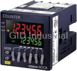
Omron H7CX-A114D1-N Counters/Timer Modules-48*48mm (1/16 DIN), 11-Pin Socket, 4 Digits, 1-Stage, Sup...
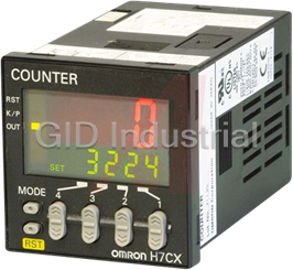
Omron H7CX-A114-N Counter/Timer Modules-48*48mm (1/16 DIN), 11-Pin Socket, 4 Digits, 1-Stage
Omron H7CX-A114S-N Counter/Timer Modules-48*48mm (1/16 DIN), 11-Pin Socket, 4 Digits, 1-Stage, Solid...
Request a Quote

The quote request has been received
Close

Facing challenges or have inquiries? Feel free to contact us!
Call Us +1-469-283-2440
What they say about us
FANTASTIC RESOURCE
One of our top priorities is maintaining our business with precision, and we are constantly looking for affiliates that can help us achieve our goal. With the aid of GID Industrial, our obsolete product management has never been more efficient. They have been a great resource to our company, and have quickly become a go-to supplier on our list!
Bucher Emhart Glass
EXCELLENT SERVICE
With our strict fundamentals and high expectations, we were surprised when we came across GID Industrial and their competitive pricing. When we approached them with our issue, they were incredibly confident in being able to provide us with a seamless solution at the best price for us. GID Industrial quickly understood our needs and provided us with excellent service, as well as fully tested product to ensure what we received would be the right fit for our company.
Fuji
HARD TO FIND A BETTER PROVIDER
Our company provides services to aid in the manufacture of technological products, such as semiconductors and flat panel displays, and often searching for distributors of obsolete product we require can waste time and money. Finding GID Industrial proved to be a great asset to our company, with cost effective solutions and superior knowledge on all of their materials, it’d be hard to find a better provider of obsolete or hard to find products.
Applied Materials
CONSISTENTLY DELIVERS QUALITY SOLUTIONS
Over the years, the equipment used in our company becomes discontinued, but they’re still of great use to us and our customers. Once these products are no longer available through the manufacturer, finding a reliable, quick supplier is a necessity, and luckily for us, GID Industrial has provided the most trustworthy, quality solutions to our obsolete component needs.
Nidec Vamco
TERRIFIC RESOURCE
This company has been a terrific help to us (I work for Trican Well Service) in sourcing the Micron Ram Memory we needed for our Siemens computers. Great service! And great pricing! I know when the product is shipping and when it will arrive, all the way through the ordering process.
Trican Well Service
GO TO SOURCE
When I can't find an obsolete part, I first call GID and they'll come up with my parts every time. Great customer service and follow up as well. Scott emails me from time to time to touch base and see if we're having trouble finding something.....which is often with our 25 yr old equipment.
ConAgra Foods