

 Manufacturers
OMRON H8BM-R

Description
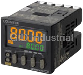
Omron H8BM-R Counter/Timer Modules-Nine Built-in Counters/Timers
Part Number
H8BM-R
Price
Request Quote
Manufacturer
OMRON
Lead Time
Request Quote
Category
Counter/Timer Modules
Specifications
Control output
Open-collector output: 100 mA max. at 30 VDC max.
Count inputs
1 to 7: 16.7 ms
Max. counting speed
30 Hz for count inputs 1 to 7,Switchable between 30 Hz and 500 Hz for count inputs 8 and 9
One-shot time
20 ms
Operating voltage range
85% to 110% of rated supply voltage (See note 1.)
Power consumption
Approx. 1.7 W (at 26.4 VDC)
Features
- Compact, short-body: 72 × 72 × 79 mm (DIN).
- Directly connectable to 2-wire DC sensors.
- Individual forecast outputs to indicate maintenance timing.
- IP54 oil-proof type at setting area for resistance to oil and water.
- Key protection function prevents incorrect operation.
- Multiple outputs: NPN/PNP.
- Pre-forecast display and machine stoppage output provided.
- Provides up to nine counters or accumulative timers. (Counter and timer functions can be used at the same time.)
- Separate digit keys to easily change settings.
Datasheet

Extracted Text
Multi-maintenance Counter/Timer (DIN 72 x 72) H8BM-R CSM_H8BM-R_DS_E_5_1 Nine Built-in Counters/Timers to Measure Equipment Operating Cycles and Times and Forecast Maintenance Timing • Provides up to nine counters or accumulative timers. (Counter and timer functions can be used at the same time.) Individual forecast outputs to indicate maintenance timing. Pre-forecast display and machine stoppage output provided. IP54 oil-proof type at setting area for resistance to oil and water. Separate digit keys to easily change settings. The H8BM-R can be used as a multi-stage preset counter.Compact, short-body: 72 × 72 × 79 mm (DIN). Key protection function prevents incorrect operation. Refer to Safety Precautions on page 7. Multiple outputs: NPN/PNP. Directly connectable to 2-wire DC sensors. Complies with UL and CSA. Ordering Information ■ Multi-maintenance Counter/Timer ■ Accessories (Order Separately) Preset stage Nameplate lettering Model Name Model Japanese H8BM-RA Hard Protective Cover (See note 1.) Y92A-72C 3-stage setting English H8BM-RB Rubber Packing (See note 1.) Y92S-25 Japanese H8BM-RAD Short-circuit plate (See note 2.) Y92S-26 1-stage setting English H8BM-RBD Note 1. A Hard Protective Cover and Rubber Packing are supplied with the Counter. 2. The H8BM-R@ is provided with short input as standard to achieve a Multi-stage Counter without having to use a short-circuit plate and external wiring. ■ Specifications Item Model H8BM-RA/RB H8BM-RAD/RBD Classification 3-stage setting 1-stage setting Mounting method Flush mounting External connections Screw terminals Degree of protection IP54 oil-proof type (case front) Display mode Up display Output mode F mode (Operation continues even when setting is reached.) Note 1. Each channel operates on a separate Reset system External, manual resets I/O. Timer operation Yes 2. The 3-stage are pre-forecast, forecast, and machine stoppage. Voltage inputs: High and low signal voltages (count, reset, short, counter No. selection, I/O Input method Pre-forecast: inhibit) Displayed only on LCD (no No-contact outputs: RUN, forecast, machine Control output No-contact outputs: RUN, forecast external output is provided). stoppage Forecast: Displayed on LCD and LED Count, preset value, counter number, and error codes displayed on 7-segment LCD and output (output for each Display Mode, reset, I/O inhibit, re-monitor modes, and key protection displayed on LCD characters counter). Output indication on LCD characters and LEDs Machine stoppage: LCD with backlight Yes Displayed on LCD and LED and output Built-in counter number 9 (counters 1 to 9) (See note 1.) (output when the count Preset stage 3-stage (See note 2.) 1-stage (See note 3.) value of one or more of counters 1 to 9 has reached Forecast value: 6 digits (999999) its machine stoppage Digits Pre-forecast value: −5 digits (See note 4.) Forecast value: 6 digits (999999) Machine stoppage: +5 digits (See note 5.) value). 3. This Counter operates on the forecast Forecast value: 99999.9 h (0.1 h or longer)/ value only. 99999.9 s (0.1 s or longer) 4. The pre-forecast value is set as a Pre-forecast value: −9999.9 h/−9999.9 s (See Forecast value: 99999.9 h (0.1 h or Time ranges negative offset in respect to the note 4.) longer)/99999.9 s (0.1 s or longer) Machine stoppage: +9999.9 h/+9999.9 s (See forecast value. note 5.) 5. The machine stoppage value is set as a positive offset in respect to the EEPROM (Data can be written 100,000 times.), Backup time for power interruption: Approx. Memory backup 10 years forecast value. 1 H8BM-R Specifications ■ Ratings ■ Characteristics Rated supply voltage 24 VDC Insulation 100 MΩ min. (at 500 VDC) (between current-carrying resistance terminals and exposed non-current-carrying metal parts) Operating voltage 85% to 110% of rated supply voltage (See note 1.) range 1,000 VAC, 50/60 Hz for 1 min (between current- Dielectric carrying terminals and exposed non-current-carrying Power consumption Approx. 1.7 W (at 26.4 VDC) strength voltage metal parts) 30 Hz for count inputs 1 to 7, Impulse 1 kV (between power terminals) Max. counting speed Switchable between 30 Hz and 500 Hz for count withstand 1.5 kV (between current-carrying terminals and exposed inputs 8 and 9 voltage non-current-carrying metal parts) Count inputs 1 to 7: 16.7 ms (ON:OFF = 1:1) ±480 kV (between power terminals) and ±480 V Count inputs 8 and 9: 16.7 ms/1 ms selectable Noise immunity (between input terminals), square-wave noise by noise (ON:OFF = 1:1) Min. counting input simulator (pulse width: 100 ns/1 µs, 1-ns rise) Reset input: 100 ms max. signal width Short input: 30 ms max. Static immunity Malfunction: 8 kV; destruction: 15 kV Counter number selection input: 30 ms max. Destruc- 10 to 55 Hz with 0.75-mm single amplitude, 2 hours Vibra- I/O inhibit input: 16.7 ms max. tion each in three directions tion One-shot time 20 ms (See note 2.) resis- Malfunc- 10 to 55 Hz with 0.5-mm single amplitude, 10 minutes tance Count, reset, short, Voltage input tion each in three directions counter number High level: 16 to 26.4 VDC Destruc- 2 Shock 300 m/s 3 times each in 6 directions selection, and I/O Low level: 0 to 3 VDC tion resis- inhibit input (input resistance: approx. 2.2 kΩ) Malfunc- 2 tance 200 m/s 3 times each in 6 directions Control output Open-collector output: 100 mA max. at 30 VDC max. tion Surrounding air Weight Approx. 250 g (Counter only) −10 to +55°C (with no icing or condensation) temperature Ambient storage −25 to +65°C (with no icing or condensation) temperature Ambient operating 25% to 85% humidity Case color Dark gray (Munsell 5Y3/1) Note 1. Ripple content: 20% max. 2. This signal is output as a carry signal when the Counter is used as a total counter. ■ Applicable Standards UL508 (See note.)/CSA C22.2 No.14 Safety standards EN61326 (EMI) EN61326 Emission Enclosure: EN61326 (EN55011 Group 1 Class A) Emission AC Mains: EN61326 (EN55011 Group 1 Class A) (EMS) EN61326 Immunity ESD: EN61326 (EN61000-4-2): Contact discharge: 4 kV, air discharge: 8 kV EMC Radiated electromagnetic field immunity: EN61326 (EN61000-4-3): 10 V/m (Amplitude modulated, 80 MHz to 1 GHz, 1,400 to 2,000 MHz) 10 V/m (Pulse-modulated, 900 MHz ±5 MHz) Immunity Burst: EN61326 (EN61000-4-4): 2 kV power-line, 1 kV I/O signal-line Immunity Surge: EN61326 (EN61000-4-5): 1 kV line to line (power line), 2 kV line to ground (power line) Immunity Conducted Disturbance: EN61326 (EN61000-4-6): 10 V (0.15 to 80 MHz) Note: Attach a waterproof cover of Y92A-72N. 2 H8BM-R Connections ■ Internal Connections H8BM-R RUN, machine stoppage, Count input 1 Forecast output 1 forecast 1 to 9 24 10 Load Count input 2 Forecast output 2 Output method Open collector 25 11 Load Count input 3 Switching capacity 30 VDC max., 100 mA max. Forecast output 3 26 12 Load Count input 4 Forecast output 4 Residual voltage 2 VDC max. 27 13 Load Count input 5 Leakage current 100 μA max. Forecast output 5 28 14 Load Count input 6 Forecast output 6 Note 1. When the load is short-circuited, the internal 17 3 Load Count input 7 Forecast output 7 circuits may be damaged. 18 4 Load 2. Connect a diode to suppress Counter surge when Count input 8 Forecast output 8 19 5 Load an inductive load is connected. Count input 9 Forecast output 9 20 6 Load Machine Counter No. selection stoppage output 23 9 Load Reset input RUN output 22 8 Load I/O inhibit input 16 OR Short input Output COM 15 7 2 OR +24 V 21 1 16 to 26.4 VDC +10% Input COM 0 V (24 VDC ) −15% Note 1. H8BM-RAD/-RBD outputs the forecast and machine stoppage values simultaneously. 2. The I/O terminals are used for both PNP and NPN. There is no polarity. ■ I/O Functions ● Inputs • Input count values. • Used as time count input signal when timer is used. Count 9 inputs • Max. counting speed receivable: Count inputs 1 to 7: 30 Hz (Min. signal input width: 16.7 ms), Count inputs 8 and 9: 30 Hz/500 Hz (Min. signal input width: 16.7 ms/1 ms) • Resets count/time value of a displayed Counter No. • Counter under reset does not operate as its output is turned OFF. Reset 1 input • Reset signal input received while re-monitor function is ON restores reset count/time value of the specified counter. • While reset signal is ON, RESET indicator lights. • When the short input is ON, an input is also received for one of the count inputs 2 to 9 when an input is received for count input 1. The Short H8BM can thus be used as a multi-stage preset counter without performing external short-circuit wiring. Counter No. selection • Specifies counter whose count/time value is to be displayed. • Inhibits count inputs of all counters. I/O inhibit • Turns OFF all forecast outputs, RUN outputs, and machine stoppage outputs. • While I/O inhibit signal is ON, INHB indicator lights. ● Outputs • Each of these outputs turns ON when its forecast value has been reached. Forecast 9 outputs • When a total counter is used, output one-shot signals as carry signals. • Retain outputs until count values are reset. RUN 1 output • Turns ON when Counter is operating normally. Machine stoppage • Turns ON when count value of one counter has reached set machine stoppage value. 1 output (Common) • Retains output until count value is reset. Note: The input and output signals are enabled when power is applied to the Counter. During a power failure, the input signals are disabled, and the output signals are turned OFF. 3 H8BM-R ■ Terminal Arrangement 22 23 24 25 26 27 28 22 23 24 25 26 27 28 Counter No. Reset input Count input 1 Count input 2 Count input 3 Count input 4 Count input 5 selection 15 16 17 18 19 20 21 15 16 17 18 19 20 21 Short input I/O inhibit input Count input 6 Count input 7 Count input 8 Count input 9 Input COM 8 9 10 11 12 13 14 Machine stoppage 8 9 10 11 12 13 14 RUN output Forecast output 1 Forecast output 2 Forecast output 3 Forecast output 4 Forecast output 5 output 1 2 3 4 5 6 7 123 456 7 Power supply: 0 V Power supply: 24 V Forecast output 6 Forecast output 7 Forecast output 8 Forecast output 9 Output COM ■ I/O Connections ● Input Circuits ● Output Circuits 5 V Output 39 V Photocoupler 1.4 kΩ 39 V INCOM OUTCOM 430 Ω Input 1.4 kΩ Note: Although the input terminals are electrically insulated from the internal Note: Although the output terminals are electrically insulated from the internal circuit, do not conduct an insulation resistance test on these terminals. circuit, do not conduct an insulation resistance test on these terminals. ● Example of Input Connections (Solid-state Switches) Two-wire Sensors The count input, counter number selection, reset input, I/O inhibit input, and short input signals are input when the two-wire Sensor turns ON. Note: Use the following two-wire Proximity Sensors: Two-wire Sensors H8BM-R Two-wire Sensors H8BM-R (1) High-level: transistor ON Switching capacity: 5 mA min. Residual All inputs All inputs voltage: 4 VDC max. (2) Low-level: transistor OFF Leakage current: 1.5 mA max. (3) Operating voltage range: 20.4 to 26.4 VDC We recommend using OMRON E2E-X@D@-N IN COM IN COM Sensors. 24 VDC 24 VDC Three-wire Sensors ● Example of Input Connections • NPN Type • PNP Type (Contact Switches) H8BM-R H8BM-R H8BM-R All inputs IN COM All inputs Sensor Sensor main main circuit circuit All inputs IN COM IN COM H8BM-R H8BM-R H8BM-R All inputs IN COM All inputs Sensor Sensor main main circuit circuit IN COM All inputs IN COM *H: Contact ON. *Use a contact which can adequately switch 13 mA at 30 V. 4 H8BM-R Operating Methods ■ Timing Charts 1. Counter (3-stage Preset Operation) 2. Timer (3-stage Preset Operation) Reset input Reset input Count input Count input 999999 99999.9 h Machine Machine stoppage value stoppage value Forecast value Forecast value Pre-forecast Pre-forecast value value 0.0 h 0 Pre-forecast Pre-forecast indicator indicator (no output) (no output) Forecast Forecast output and output and indicator indicator Machine Machine stoppage output stoppage output and indicator and indicator 3. Total Counter Operation 4. Total Timer Operation Reset input Reset input Count input Count input 99999.9 h 999999 0 0.0 h Forecast Forecast output output One-shot time: 20 ms (indicator) (indicator) Note: The count will return to 0 when 999999 is exceeded. When the power supply is turned OFF, the display and outputs will turn OFF, but the current count/time value will be stored in internal memory. Nomenclature The following indicators light to show that the count value has reached the preset value and that the output has turned ON. ● Initial Setting Mode Indicator Indicates that the system is in the initial ● Control Output Indicator (Red LED): • Pre-forecast value: LCD lights setting mode. • Forecast value: RED LED lights • Machine stoppage value: ● I/O Inhibit Indicator ● Control Output Indicator (LCD) Indicator flashes between red and green Indicates that the I/O inhibit input signal is and LCD output indicator flashes. ON. ● Set Mode Indicator ● Re-monitor Indicator RUN mode OFF Indicates that the system is in the re-monitor Forecast value function operation. Pre-forecast value ● RESET Indicator Machine stoppage value Indicates that the system is resetting. ● Current Value (10-mm Height) ● Key Protection Indicator Indicates the current count Indicates that operation of the keys on (current time in timer mode). the front panel is disabled. ● Time Range Indicator ● Counter No. Indicator s: seconds, h: hours Indicates the number of the counter whose data is currently displayed. ● Multiplication Counter Indicator Indicates that the system is in multiplication ● RESET Key counter function operation. Resets the count value and output signals. ● Preset Value (7-mm Height) ● COUNTER No. Key Indicates the forecast value during RUN operation. Selects the counter in sequence each time Indicates the set value in each setting mode. this Selector is pressed: ● Up Keys 1 to 6 1→2→3→4→5→6→7→8→9 Each of these keys increments the preset value of (Any counter whose forecast value is set to the corresponding digit, each time it is pressed. 0 is skipped in RUN mode.) 0→1→2→3→4→5→6→7→8→9 ● MODE Key Selects the mode in sequence each time this key is pressed: ● SET Key Inputs the set or changed data. Forecast Pre-forecast Machine RUN Value value stoppage value Note: Models with only 1-stage setting (H8BM-RAD/RBD) are not provided with pre-forecast and machine stoppage output function; only the forecast output function is provided. 5 Count value Count value Time value Time value H8BM-R Dimensions (Unit: mm) ■ Counter ● Counter H8BM-R 85.7 79 75 64.5 55 6 9 11 36 75 72 × 72 59 67.5 × 67.5 Hard Protective Cover (transparent) ■ Installation ● Installation Diagram ● Panel Cutouts To mount the Counter, attach the two supplied brackets to the The panel cutout is as shown below (according to DIN 43700). left and right sides of the Counter, and securely tighten the The mounting panel thickness must be 1 to 5 mm. Mount the knurled screws on the brackets by hand, keeping the Counter Counter so that the ambient temperature will not exceed 55°C. balanced on the right and left. The performance may not be 78 min. +0.7 satisfactory if the screws are loose or excessively tightened. If 68 −0 the knurled screws are excessively tightened with pliers or +0.7 68 other tool, damage may result. −0 13.7 78 min. 75 + α 57.5 Be sure that there is α no gap between the Supplied brackets and the Attach the brackets in mounting knurled screws once line with the rail guides brackets (2) the knurled screws (ridges) on the case. have been tightened. ● Spacing with Other Devices Provide enough space around the Counter when mounting it to ensure a proper working space. Hard Protective Cover (transparent) 100 Rubber packing Knurled screw Mounting panel ISO4757 Phillips screwdriver #2 80° M 3×5 screws are used. Select solderless terminals referring to the figure below. 3.2 5.8 Other components 6 H8BM-R Safety Precautions Refer to Safety Precautions for All Counters. (17) Separate the input devices, input wiring, and Counter as far CAUTION as possible from sources of noise and power lines carrying noise. Fire may occasionally occur. Tighten terminal screws (18) The life of internal parts may be reduced if Counters are securely to a tightening torque of 0.5 to 0.6 N·m. mounted in close proximity to each other. (19) Maintain voltage fluctuations in the power supply within the Minor electric shock, fire, or Product failure may specified range. occasionally occur. Do not disassemble, modify, or (20) Use a switch, relay, or other contacts so that the rated repair the Product or touch the interior of the Product. power supply voltage will be reached within 0.1 s. If the power supply voltage is not reached quickly enough, the Minor electric shock, fire, or Product failure may power source may fail to reset or the outputs may fall to occasionally occur. Do not allow any pieces of metal operate correctly. or conductors or any clippings or cuttings resulting (21) Do not leave the Counter for long periods at a high from installation work to enter the Product. temperature with output current in the ON state. Doing so may result in the premature deterioration of internal Precautions for Safe Use components (e.g., electrolytic capacitors). (22) Periodically inspect and replace the rubber packing. It may In order to ensure safe operation, be sure to observe the deteriorate, expand, shrink, or harden in some operation following points. environments. (1) Store the Counter within the specified temperature range. If (23) Check that the backlight, output indicators, and LCD are the Counter has been stored at a temperature under operating normally. Some operating environments may −10°C, allow the Counter to stand at room temperature for accelerate deterioration of the indicators, LCD, and resin at least 3 hours before using it. components and cause display malfunctions. Periodically (2) Use the Counter within the ratings specified for ambient inspect and replace parts. operating temperature and ambient operating humidity. (24) Be sure that the voltage applied is within the specified (3) Do not operate the Counter in any of the following range; otherwise, the internal elements of the Counter may locations. be damaged. • Locations subject to sudden or extreme changes in temperature. Precautions for Correct Use • Locations where high humidity may result in (1) Be sure that the capacity of the power supply is sufficient. condensation. The Counter may not start due to the capacity of the power (4) Use the Counter within the specified ratings for vibration supply or the inrush current that may flow for an instant and shock. (approx. 1.6 A for 12 ms) when the Counter is turned ON. (5) Do not use the Counter in locations subject to excessive (2) The Power Supply, input, and output circuits are electrically dust, corrosive gases, or direct sunlight. isolated inside the Counter. (6) When using the Counter in environments subject to large When turning the power ON and OFF, input signal amounts of static electricity (e.g., pipes carrying molding reception is sometimes possible, sometimes not possible, materials, powders, or fluid materials), separate the and sometimes unstable, as shown in the diagram below. Counter as far as possible from the sources of static ON electricity. Power supply OFF (7) Use the Counter within the specified ratings for vibration, 200 ms 0 to 100 ms 10 ms 0 to 900 ms shock, water immersion, and exposure to oil. Un- Input signal reception Impossible Possible Unstable Impossible stable (8) Always use a thermo-switch on the load circuit when a heater is used. Turn on or off the operating power source all at once by (9) Do not use organic solvents (such as paint thinner or using switch or relay contact. benzene), strong alkalis, or strong acids because they will (3) EEPROM is used to back up the memory if the power fails. damage the external finish of the Counter. Data can be written to EEPROM 100,000 times. Data is (10) Install a switch or circuit breaker that allows the operator to written to the EEPROM when the settings are changed or immediately turn OFF the power, and label it to clearly deleted or the power is turned OFF. indicate its function. (4) The Counter uses a constant read-in system, so outputs (11) Be sure that all terminals are wired correctly. will turn ON if the set values are changed during operation (12) Do not connect more than two crimp terminals to the same such that the set value is equal to or less than the count terminal. value. (13) Use the specified wires for wiring. (5) Dispose of the Counter in accordance with all local Applicable Wires industrial waste disposal procedures. AWG22 to AWG14 (6) The water and oil resistance will be lost if the front sheet is 2 (cross-sectional area of 0.326 to 2.081 mm ) peeled off or torn. Solid or twisted wires of copper Do not use the Counter if the front sheet is peeled or torn. (14) Always maintain the load current within specifications. (15) Use a switch, relay, or other contact device to turn OFF the power supply instantaneously. Outputs may malfunction and memory errors may occur if the power supply voltage is decreased gradually. (16) Up to two wires of the same size and type can be inserted into a single terminal. 7 H8BM-R Operation 1. DIP Switch Settings Key protection and whether each counter operates as a counter or a timer are specified on a DIP switch provided on the side panel of the Counter. Open the cover of the switch compartment on the side of the Counter to access the DIP switch. Note 1. Set the DIP switch (except for Key Protection) before turning ON the power. Changes to DIP switch settings while the Counter is operating Enabled Timer will be ignored. Power must be turned OFF then back ON 1 2 3 4 5 6 7 8 9 10 Key Protection after changing the settings. (Can always be switched.) Changes to DIP switch settings are also enabled when Counter Disabled changing to initial setting mode because the same operation is performed as when cycling the power. 2. Key protection can be set for each key. Key protection will be performed based on the details set in the initial setting mode. DIP switch compartment Refer to Initial Setting Mode on page 11. 2. Changing Mode The system will always enter the RUN mode after the power supply is turned ON. Key SET MODE Key Press for 4 s min. Press for 4 s min. Normal Mode Initial Setting Mode Re-monitor mode This mode is for the operational state. Refer to page 11 for Refer to page 12 for RUN mode The present value, set value, counter number, information on the initial information on the and output status will be displayed. setting mode. re-monitor mode. MODE Key 23456 3 200000 This mode is for setting forecast values. Forecast value mode Values can be independently set for each counter number. MODE Key 23456 3 200000 This mode is for setting pre-forecast values. Pre-forecast value mode* The pre-forecast will be displayed (LCD) as a value before the forecast value. Set that value as the pre-forecast value. Values can be independently set for each counter number. Set the pre-forecast value by deviation. MODE Key 23456 3 -- 500 This mode is for setting machine stoppage values. Machine stoppage mode* Machine stoppage (output/LCD) will occur at a value in excess of the forecast value. Set that value as the machine stoppage value. Values can be independently set for each counter number, but machine stoppage output will be performed if any counter from No. 1 to 9 reaches the machine stoppage MODE Key value. Set the machine stoppage value by deviation. Note: I/O operations are always performed regardless of the mode. If no key is pressed for 1 minute in each mode, 23456 the RUN mode is automatically restored. 3 10000 will flash. 3 The modes marked * are not provided on the 1- stage type Counter. 8 H8BM-R 3. Setting/Changing Data ● Setting/Changing Forecast Value ● Setting and Changing Pre-forecast Values (3-stage Type) 1. In the RUN mode, press the Key to enter the forecast MODE 1. Press the MODE Key to enter the value setting mode. pre-forecast value setting mode. 0 • The same counter number as in the RUN • The same counter number as in the 0 forecast value setting mode is displayed mode is displayed after changing to 1 100000 forecast value mode. after changing to pre-forecast value mode. • “-” is automatically displayed. 2 -- 0 CNT No. 2. Press the Key (or turn ON CNT No. 2. Press the Key (or turn ON the counter number selection the counter number selection input) to select the counter whose input) to select the counter whose 0 0 data is to be set or changed. data is to be set or changed. 2 2 • The counters are selected in sequence 0 Next, press the UP Key -- 1000 CNT No. each time the Key is pressed, from ( ) to set or change the pre- 1 to 5 1 through 9, then back to 1. forecast value. 1→2→3→4→5→6→7→8→9 • The CNT No. Key does not need to be pressed if the counter does not need to • A counter can also be selected by inputting the counter number selection be changed. input. 3. Press the SET Key to enter the 3. Use the Keys ( ) to UP 1 to 6 set value. change the values of the digits. • If no key is pressed within 5 seconds after • When an Key is pressed, the UP the SET Key has been pressed, the 0 0 corresponding digit starts flashing. RUN mode is automatically restored. • The preset value is zero-suppressed. Each 1 -- 1000 2 10000 time the Key is pressed, the value UP changes in sequence, ● Setting and Changing the Machine Stoppage Value (3- from 1→2→3→4→5→6→7→8→9→0. stage Type) 1→2→3→4→5→6→7→8→9→0 0 1. Press the MODE Key to enter the Machine Stoppage Value setting In the following example, the forecast 2 35000 mode. 0 value of counter 2 is set to 35000. • The same counter number as in the pre- forecast value setting mode is displayed 2 0 4. Press the Key to enter the SET after changing to machine stoppage value setting mode. set value. • “+” is automatically displayed. • If no key is pressed within 5 seconds after 0 the Key has been pressed, RUN SET CNT No. mode is automatically restored. 2. Press the Key (or turn ON 2 35000 the counter number selection input) (The display is changed automatically to select the counter whose data is 0 after the set forecast value has to be set or changed. flashed.) Next, press the Key 2 UP 2500 0 ( 1 5 ) to set or change the to 2 35000 machine stoppage value. CNT No. • The Key does not need to be pressed if the counter does not need to be changed. 3. Press the SET Key to enter the set value. • If no key is pressed within 5 seconds after 0 the SET Key has been pressed, the RUN mode is automatically restored. 2 2500 9 H8BM-R 4. Special Set Values 7. Deleting Count Value ● Setting Counters That Will Not Use the Machine 1. Resetting Individual Counters Stoppage Output (3-stage Type) (1)Press the Key (or turn ON the CNT No. The machine stoppage output will not be counter number selection input) to used for counters for which the machine select the counter to be reset. 100000 • The counter value can be reset in all modes stoppage value has been set to +99999 0 except initial setting mode and re-monitor 8 (+9999.9 h/+9999.9 s). 100000 mode. 7 99999 (2)Press the RESET Key (or turn ON the reset input) to reset the count value to 0 for that counter only. 0 00 8 100000 7 99999 2. Resetting of All Counters at the Same Time ● Setting Counters That Will Not Be Used Press and hold both the CNT No. and Input and output operations will not RESET Keys for 3 seconds to reset the occur for counters for which the forecast count value for all counters to 0. 0 • The same operation is achieved by value has been set to 0 (0.0 h/0.0 s). 0 simultaneously turning ON the counter number • If the forecast value is set to 0 (0.0 h/0.0 s), the a100000 selection and reset inputs for 3 seconds. pre-forecast and machine stoppage values will 9 0 automatically be set to 0 (0.0 h/0.0 s). 8. All Clear ● Setting Counters to Be Used as Total Counters/Timers Press and hold the RESET and SET Counters can be used as total counters/ Keys for 3 seconds to reset the count timers if the forecast value for that values, pre-forecast values, forecast 23456 counter is set to 999999 (99999.9 h/ 0 values, and machine stoppage values to 0 for all counters. 3 99999.9 s). 200000 8 999999 • The counter number after All Clear has been • The machine stoppage output will no longer be executed will automatically change to 1. output for that counter. • When using a counter as a total counter, the forecast output for that counter when the count value changes from 999999 to 0 will be a one- shot output of 20 ms to indicate a carry. 0 1 0 5. Checking Count Values (RUN Mode) 9. Control Output Display Press the CNT No. Key (or turn ON the The pre-forecast value, forecast, and machine stoppage status counter No. selection input) in RUN display will be as follows: mode to check the count value for each 9000 counter. ● Pre-forecast Values (3-stage 1100000 • The counter number changes in sequence Type) each time the CNT No. Key is pressed (or the input turns ON), from 1 through The output display for counters for 90000 9, then back to 1. which the count value has reached the 1→2→3→4→5→6→7→8→9 1100000 pre-forecast set value will be lit. Note: However, any counter whose forecast value is set to 0 (0.0 h/0.0 s) will be • Pre-forecast values are only displayed as a skipped. message and are not output. ● Forecast Outputs 6. Other Indicators A red indicator will light at the top of the 100000 output display section for the lit counter Timer Operation Display number and the output will turn ON. The period on the count value display 1 100000 ● Machine Stoppage Output (3- will flash while the count input is ON and 00 stage Type) the Timer is in h mode. 1 10000 The entire background will alternate • The timer operation measures time by totaling between red and green and the the ON time of the count input. output display for the counter with a 110000 machine stoppage will flash. 1 100000 Note: If the pre-forecast, forecast, or machine stoppage output turns ON, the counter number display will automatically change to that number and the count value will be displayed (in RUN mode only). 10 H8BM-R 10. Initial Setting Mode This mode is for setting a number of convenient functions. • Refer to page 8 for the normal modes. Normal • If the mode is switched to the initial setting mode during operation, 23456 Mode operation will continue. 3200000 • The characters displayed in reverse video are the default settings. MODE Key Press for 4 s min. The max. counting speed switching for counters 8 and 9 can be 1. Max. Counting Speed changed. Switching count • Press the UP Key to switch between 30 Hz and 500 Hz. MODE • Press the SET Key to enter the set value. 30h MODE Key The Timer time rages can be changed. 2. Time Rages • Press the CNT No. Key to change the time rages. Select the counter number. ti rng MODE • Press the UP Key to switch between 0.1 h and 0.1 s. • Press the Key to enter the set value. 1 01 SET Note: The time unit is displayed when the counter is set to a timer on the DIP switch. MODE Key Counter 1 inputs can be input to other counters. 3. Short Function ex. if “5” is selected, Counter 1 inputs can be input to counters 2 to 5. short • Press the Key and select the number of counters for which the short UP MODE function is to be enabled. 9 9 →OFF→2→3→4→5→6→7→8 • Press the SET Key to enter the setting. MODE Key Note: The short input is read only when the power is turned ON. They are ignored if input during operation. 4. RESET Key Protection The RESET Key can be protected. Initial • Press the UP Key and select the counter for which RESET Key protection is Setting Mode eset to be set. Mode MODE ON (ch1 to 9) → ON (ch8/9) → ON (ch9) → OFF on • Press the SET Key to enter the setting. Note 1. The Reset of All Counters and All Clear using the RESET Key are disabled if the RESET Key Protection function is turned ON. MODE Key 2. Key Protection function is activated by setting the Dip Switch to 10. 5. MODE Key Protection The MODE Key can be protected. off • Press the UP Key to switch between and on. Mode ode • Press the Key to enter the setting. MODE SET Note: Key Protection function is activated by setting the Dip Switch to 10. off MODE Key 6. SET Key Protection The SET Key can be protected. • Press the UP Key to switch between off and on. Mode set • Press the SET Key to enter the setting. MODE Note: Key Protection function is activated by setting the Dip Switch to 10. off MODE Key 7. Multiplication Counter • Press the UP Key to switch between off and on. • Press the SET Key to enter the setting. ult MODE MULTI Note: A Multiplication Counter is a batch counter that increments the count of off counter 9 each time the forecast value of counter 1 is reached. MODE Key 11 H8BM-R 11. Re-monitor Mode 12. Self-diagnosis Function Use this mode to return to the count value before resetting if the The following displays are made when errors occur. Display Error content All I/O Countermeasure count value is mistakenly reset. Turn OFF the power or press the 1. In the RUN mode, hold the SET Key to clear the error and RESET Key for 4 seconds min. to change to CPU Errors Prohibited restore the settings and count e1 values to the values before the re-monitor mode. 100000 error. • The previous values that have been reset Turn OFF the power or press the will be displayed. 1 100000 RESET Key to clear the error and • Only the display changes. Internal counting Memory Errors Prohibited e2 return the count values for all operations are not affected. counters to 0. • The counter number remains unchanged on RUN display when the mode is changed to Turn OFF the power supply or re-monitor display. Key Errors Prohibited press the RESET Key to clear key e3 errors. CNT No. 2. Press the Key (or turn ON the counter number selection input) to select the counter 23456 to be re-monitored. 3 200000 3. When the RESET Key is pressed (or the reset input turns ON), the re-monitor value will flash 3 times 23456 and the only the count value for 3 200000 that counter will be returned to the value prior to being reset. 12 Read and Understand This Catalog Please read and understand this catalog before purchasing the products. Please consult your OMRON representative if you have any questions or comments. Warranty and Limitations of Liability WARRANTY OMRON's exclusive warranty is that the products are free from defects in materials and workmanship for a period of one year (or other period if specified) from date of sale by OMRON. OMRON MAKES NO WARRANTY OR REPRESENTATION, EXPRESS OR IMPLIED, REGARDING NON-INFRINGEMENT, MERCHANTABILITY, OR FITNESS FOR PARTICULAR PURPOSE OF THE PRODUCTS. ANY BUYER OR USER ACKNOWLEDGES THAT THE BUYER OR USER ALONE HAS DETERMINED THAT THE PRODUCTS WILL SUITABLY MEET THE REQUIREMENTS OF THEIR INTENDED USE. OMRON DISCLAIMS ALL OTHER WARRANTIES, EXPRESS OR IMPLIED. LIMITATIONS OF LIABILITY OMRON SHALL NOT BE RESPONSIBLE FOR SPECIAL, INDIRECT, OR CONSEQUENTIAL DAMAGES, LOSS OF PROFITS OR COMMERCIAL LOSS IN ANY WAY CONNECTED WITH THE PRODUCTS, WHETHER SUCH CLAIM IS BASED ON CONTRACT, WARRANTY, NEGLIGENCE, OR STRICT LIABILITY. In no event shall the responsibility of OMRON for any act exceed the individual price of the product on which liability is asserted. IN NO EVENT SHALL OMRON BE RESPONSIBLE FOR WARRANTY, REPAIR, OR OTHER CLAIMS REGARDING THE PRODUCTS UNLESS OMRON'S ANALYSIS CONFIRMS THAT THE PRODUCTS WERE PROPERLY HANDLED, STORED, INSTALLED, AND MAINTAINED AND NOT SUBJECT TO CONTAMINATION, ABUSE, MISUSE, OR INAPPROPRIATE MODIFICATION OR REPAIR. Application Considerations SUITABILITY FOR USE OMRON shall not be responsible for conformity with any standards, codes, or regulations that apply to the combination of products in the customer's application or use of the products. At the customer's request, OMRON will provide applicable third party certification documents identifying ratings and limitations of use that apply to the products. This information by itself is not sufficient for a complete determination of the suitability of the products in combination with the end product, machine, system, or other application or use. The following are some examples of applications for which particular attention must be given. This is not intended to be an exhaustive list of all possible uses of the products, nor is it intended to imply that the uses listed may be suitable for the products: · Outdoor use, uses involving potential chemical contamination or electrical interference, or conditions or uses not described in this catalog. · Nuclear energy control systems, combustion systems, railroad systems, aviation systems, medical equipment, amusement machines, vehicles, safety equipment, and installations subject to separate industry or government regulations. · Systems, machines, and equipment that could present a risk to life or property. Please know and observe all prohibitions of use applicable to the products. NEVER USE THE PRODUCTS FOR AN APPLICATION INVOLVING SERIOUS RISK TO LIFE OR PROPERTY WITHOUT ENSURING THAT THE SYSTEM AS A WHOLE HAS BEEN DESIGNED TO ADDRESS THE RISKS, AND THAT THE OMRON PRODUCTS ARE PROPERLY RATED AND INSTALLED FOR THE INTENDED USE WITHIN THE OVERALL EQUIPMENT OR SYSTEM. PROGRAMMABLE PRODUCTS OMRON shall not be responsible for the user's programming of a programmable product, or any consequence thereof. Disclaimers CHANGE IN SPECIFICATIONS Product specifications and accessories may be changed at any time based on improvements and other reasons. It is our practice to change model numbers when published ratings or features are changed, or when significant construction changes are made. However, some specifications of the products may be changed without any notice. When in doubt, special model numbers may be assigned to fix or establish key specifications for your application on your request. Please consult with your OMRON representative at any time to confirm actual specifications of purchased products. DIMENSIONS AND WEIGHTS Dimensions and weights are nominal and are not to be used for manufacturing purposes, even when tolerances are shown. PERFORMANCE DATA Performance data given in this catalog is provided as a guide for the user in determining suitability and does not constitute a warranty. It may represent the result of OMRON’s test conditions, and the users must correlate it to actual application requirements. Actual performance is subject to the OMRON Warranty and Limitations of Liability. ERRORS AND OMISSIONS The information in this document has been carefully checked and is believed to be accurate; however, no responsibility is assumed for clerical, typographical, or proofreading errors, or omissions. 2011.4 In the interest of product improvement, specifications are subject to change without notice. OMRON Corporation Industrial Automation Company http://www.ia.omron.com/ (c)Copyright OMRON Corporation 2011 All Right Reserved.
Frequently asked questions
How does Industrial Trading differ from its competitors?

Is there a warranty for the H8BM-R?
Which carrier will Industrial Trading use to ship my parts?
Can I buy parts from Industrial Trading if I am outside the USA?
Which payment methods does Industrial Trading accept?
Why buy from GID?

Quality
We are industry veterans who take pride in our work

Protection
Avoid the dangers of risky trading in the gray market

Access
Our network of suppliers is ready and at your disposal

Savings
Maintain legacy systems to prevent costly downtime

Speed
Time is of the essence, and we are respectful of yours
Related Products
Omron H7CX-A114D1-N Counters/Timer Modules-48*48mm (1/16 DIN), 11-Pin Socket, 4 Digits, 1-Stage, Sup...
Omron H7CX-A114-N Counter/Timer Modules-48*48mm (1/16 DIN), 11-Pin Socket, 4 Digits, 1-Stage
Omron H7CX-A114S-N Counter/Timer Modules-48*48mm (1/16 DIN), 11-Pin Socket, 4 Digits, 1-Stage, Solid...
Request a Quote

The quote request has been received
Close

Facing challenges or have inquiries? Feel free to contact us!
Call Us +1-469-283-2440
What they say about us
FANTASTIC RESOURCE
One of our top priorities is maintaining our business with precision, and we are constantly looking for affiliates that can help us achieve our goal. With the aid of GID Industrial, our obsolete product management has never been more efficient. They have been a great resource to our company, and have quickly become a go-to supplier on our list!
Bucher Emhart Glass
EXCELLENT SERVICE
With our strict fundamentals and high expectations, we were surprised when we came across GID Industrial and their competitive pricing. When we approached them with our issue, they were incredibly confident in being able to provide us with a seamless solution at the best price for us. GID Industrial quickly understood our needs and provided us with excellent service, as well as fully tested product to ensure what we received would be the right fit for our company.
Fuji
HARD TO FIND A BETTER PROVIDER
Our company provides services to aid in the manufacture of technological products, such as semiconductors and flat panel displays, and often searching for distributors of obsolete product we require can waste time and money. Finding GID Industrial proved to be a great asset to our company, with cost effective solutions and superior knowledge on all of their materials, it’d be hard to find a better provider of obsolete or hard to find products.
Applied Materials
CONSISTENTLY DELIVERS QUALITY SOLUTIONS
Over the years, the equipment used in our company becomes discontinued, but they’re still of great use to us and our customers. Once these products are no longer available through the manufacturer, finding a reliable, quick supplier is a necessity, and luckily for us, GID Industrial has provided the most trustworthy, quality solutions to our obsolete component needs.
Nidec Vamco
TERRIFIC RESOURCE
This company has been a terrific help to us (I work for Trican Well Service) in sourcing the Micron Ram Memory we needed for our Siemens computers. Great service! And great pricing! I know when the product is shipping and when it will arrive, all the way through the ordering process.
Trican Well Service
GO TO SOURCE
When I can't find an obsolete part, I first call GID and they'll come up with my parts every time. Great customer service and follow up as well. Scott emails me from time to time to touch base and see if we're having trouble finding something.....which is often with our 25 yr old equipment.
ConAgra Foods