

 Manufacturers
OMRON H7HP
Description
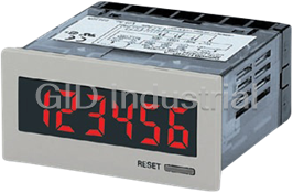
Omron H7HP Counter/Timer Modules-IN 72 x 36-mm Total Counter/Time Counter
Part Number
H7HP
Price
Request Quote
Manufacturer
OMRON
Lead Time
Request Quote
Category
Counter/Timer Modules
Specifications
Digits
6 digits (15-mm-high characters)
Dimensions
72 x 36 x 66 mm (W x H x D)
Display
7-segment, negative transmissive LCD (with red backlight)
External connections
Screw terminals
External power supply
50 mA at 12 VDC
Function
Total counter/time counter
Max. counting speeds
30 Hz or 5 kHz (selected via DIP switch)
Mounting method
Flush mounting
Operating voltage range
85% to 110% of rated supply voltage
Power consumption
100 to 240 VAC: 6.5 VA max. 12 to 24 VDC: 0.6 W max.
Rated supply voltage
100 to 240 VAC (50/60 Hz)
Features
- and parts.
- Compact (66 mm) body.
- Finger-protection terminal block cover prevents electrical shock and conforms to VDE0106, Part 100.
- High-visibility, negative transmissive LCD display with built-in red LED backlight at low power consumption.
- IP66 with oil resistance and NEMA4 are achieved by unifying the front with the casing case and using oil-resistant materials
- Just change a switch setting for either an NPN or PNP input.
- Large, easy-to-read displays: 15-mm-high characters for 6-digit models; 12-mm-high characters for 8-digit models.
- Supports both external resetting and manual resetting.
- Switch 6-digit models between total counter and time counter operation.
Datasheet

Extracted Text
Total Counter/Time Counter (DIN 72 x 36) H7HP CSM_H7HP_DS_E_4_1 DIN 72 x 36-mm Total Counter/Time Counter with Easy-to-read Displays and Water and Oil Resistance Equivalent to IP66 • Large, easy-to-read displays: 15-mm-high characters for 6-digit models; 12-mm-high characters for 8-digit models. High-visibility, negative transmissive LCD display with built-in red LED backlight at low power consumption. IP66 with oil resistance and NEMA4 are achieved by unifying the front with the casing case and using oil-resistant materials and parts. Compact (66 mm) body. Switch 6-digit models between total counter and time counter operation. Just change a switch setting for either an NPN or PNP input. Supports both external resetting and manual resetting. Finger-protection terminal block cover prevents electrical shock and conforms to VDE0106, Part 100. Safety standards: UL, CSA, EMC (EN 61326), CE Marking. Model Number Structure ■ Model Number Legend H7HP-@@@@ 1 2 3 4 1. Classification 3. Supply Voltage None: 100 to 240 VAC A: Total counter/time counter C: Total counter D: 12 to 24 VDC 2. Digits 4. Case Color None: 6 digits None: Light gray (Munsell 5Y7/1) 8: 8 digits B: Black Ordering Information ■ List of Models Supply voltage 6-digit total counter/time counter 8-digit total counter Light gray Black Light gray Black 100 to 240 VAC H7HP-A H7HP-AB H7HP-C8 H7HP-C8B 12 to 24 VDC H7HP-AD H7HP-ADB H7HP-C8D H7HP-C8DB 1 H7HP Specifications ■ Ratings Item 6-digit total counter/time counter 8-digit total counter H7HP-A H7HP-AD H7HP-C8 H7HP-C8D Rated supply voltage 100 to 240 VAC (50/60 Hz) 12 to 24 VDC (see note 1) 100 to 240 VAC (50/60 Hz) 12 to 24 VDC (see note 1) External power supply 50 mA at 12 VDC --- 50 mA at 12 VDC --- Operating voltage range 85% to 110% of rated supply voltage Power consumption 100 to 240 VAC: 6.5 VA max. 12 to 24 VDC: 0.6 W max. Dimensions 72 x 36 x 66 mm (W x H x D) Mounting method Flush mounting External connections Screw terminals Degree of protection Panel surface: IP66 with oil resistance, NEMA 4 (indoors). Panel surface only: IEC IP66. IEC IP66 Display 7-segment, negative transmissive LCD (with red backlight) Digits 6 digits (15-mm-high characters) 8 digits (12-mm-high characters) Function Total counter/time counter (selected via DIP switch) Total counter Input mode Up/down (individual) (total counter), or accumulative Up/down (individual) (time counter) Max. counting speeds 30 Hz or 5 kHz (selected via DIP switch) Counting range –99999 to 999999 –9999999 to 99999999 Time specification 0.1 to 99999.9 h/1 s to 99 h 59 min 59 s --- Timing accuracy ±100 ppm (–10°C to 55°C) --- Memory backup EEP-ROM: 200,000 operations min. Input Input signals Count 1/start, count 2/gate, reset, and key protection (see note 2) Input method No-voltage input (NPN transistor input) or voltage input (PNP transistor input) (selected via DIP switch) Count, start, No-voltage input (NPN transistor input) gate, reset Short-circuit (ON) impedance: 1 kΩ max. Short-circuit (ON) residual voltage: 2 VDC max. Open (OFF) impedance: 100 kΩ min. Voltage input (PNP transistor input) Short-circuit (ON) impedance: 1 kΩ max. ON voltage: 9 to 24 VDC OFF voltage: 5 VDC max. Open (OFF) impedance: 100 kΩ max. Key protection No-voltage input (NPN transistor input) Short-circuit (ON) impedance: 1 kΩ max. Short-circuit (ON) residual voltage: 0.5 VDC max. Open (OFF) impedance: 100 kΩ min. Input re- Reset Time counter: 20 ms; total counter: 20 ms or 1 ms (automatically switched according to counting speed) sponse Start Time counter: 20 ms speed Key protection Approx. 1 s Approx. 1 s Reset system External and manual resets Note: 1. Contains 20% ripple (p-p) max. 2. Only a non-voltage input (NPN transistor) is possible for the key protection input. The key protection input will be a non-voltage input even if the NPN/PNP input mode is set to PNP. Key protection is used to prohibit operating the Reset Key. The reset input terminals will still be functional. 2 H7HP ■ Characteristics Insulation resistance 100 MΩ min. (at 500 VDC) Dielectric strength 2,000 VAC, 50/60 Hz for 1 min between current-carrying terminal and exposed non-current-carrying metal parts (AC model) 1,000 VAC, 50/60 Hz for 1 min between current-carrying terminal and exposed non-current-carrying metal parts (DC model) 2,000 VAC, 50/60 Hz for 1 min between power terminals and control input terminals (AC model) Impulse withstand voltage 3 kV (between power terminals) (1 kV for 12-to-24-VDC models) 4.5 kV (between current-carrying terminal and exposed non-current-carrying metal parts) (1.5 kV for 12-to-24-VDC models) Noise immunity ±1.5 kV (between AC power terminals), ±480 V (between DC power terminals), ±480 V (between input terminals); square-wave noise by noise simulator (pulse width: 100 ns/1 µs, 1-ns rise) Static immunity Display: Malfunction: 8 kV Destruction: 15 kV DIP switch: Malfunction: 4 kV Destruction: 8 kV Vibration resistance Destruction: 10 to 55 Hz with 0.75-mm single amplitude, 2 hours each in three directions Malfunction: 10 to 55 Hz with 0.5-mm single amplitude, 10 minutes each in three directions 2 Shock resistance Destruction: 294 m/s each in three directions 2 Malfunction: 196 m/s each in three directions Ambient temperature Operating: –10°C to 55°C (with no icing) Storage: –25°C to 65°C (with no icing) Ambient humidity Operating: 35% to 85% EMC (EMI) E61326 Emission Enclosure: EN55011 Group 1 class A Emission AC Mains: EN55011 Group 1 class A (EMS) EN61326 Immunity ESD: EN61000-4-2: 4 kV contact discharge (level 2) 8 kV air discharge (level 3) Immunity RF-interference: EN61000-4-3: 10 V/m (Amplitude-modulated, 80 MHz to 1 GHz) (level 3); 10 V/m (Pulse-modulated, 900 MHz ±5 MHz) (level 3) Immunity Conducted Disturbance: EN61000-4-6: 10 V (0.15 to 80 MHz) (according to EN61000-6-2) Immunity Burst: EN61000-4-4: 2 kV power-line (level 3); 2 kV I/O signal-line (level 4) Immunity Surge: EN61000-4-5: 1 kV line to lines (power and output lines) (level 2); 2 kV line to ground (power and output lines) (level 3) Immunity Voltage Dip/Interruption: EN61000-4-11: 0.5 cycle, 100% (rated voltage) Approved standards UL508, CSA22.2 No.14, conforms to EN61010-1, VDE0106/P100 Case color Rear section: Gray smoke; Front section: 5Y7/1 (light gray) or N1.5 (black) Weight Approx. 115 g 3 H7HP Connections ■ Terminal Arrangement Note: 1. Incremented for count 1 (CP1) inputs; decremented for count 2 (CP2) inputs. 2. Non-contact input is also available. AC Models H7HP-A H7HP-C8 External power supply External power supply 100 to 240 VAC 100 to 240 VAC 12 VDC 50 mA max. 12 VDC 50 mA max. Power Power Power Power Unused Unused Unused 0 V 12 VDC Unused Unused Unused 0 V 12 VDC supply supply supply supply 56 78 9 10 11 56 7 8 9 10 11 12 34 12 34 Key Key Count 1 Count 2 Reset Count 1 Count 2 Reset protection protection input or input or input input input input input input start input gate input NPN mode NPN mode PNP mode PNP mode DC Models H7HP-AD H7HP-C8D 12 to 24 VDC 12 to 24 VDC Power Power 0 V Unused Unused Unused Unused Unused supply 0 V Unused Unused Unused Unused Unused supply 56 78 9 10 11 56 78 9 10 11 12 34 12 34 Key Key Count 1 Count 2 Reset Count 1 Count 2 Reset protection protection input or input or input input input input input input start input gate input NPN mode NPN mode PNP mode PNP mode Operation ■ DIP Switch Settings Switches 1 to 4 are all set to OFF before shipping. H7HP-C@ Pin no. Item OFF ON 1Unused --- --- 2 Counting speed 30 Hz 5 kHz (note) H7HP-A@ 3 Input mode (note) NPN PNP Pin no. Item OFF ON 4Unused --- --- 1 Function Total counter Time counter Note: When the setting has been changed, turned power off and on 2 Counting speed 30 Hz 5 kHz to continue. The display will show “0” when the power is turned (note) back on. Time range (note) 99999.9 h 99 h 59 min 59 s 3 Input mode (note) NPN PNP 4 Unused --- --- 4 H7HP ■ Operating Modes Total Counters Reset input CP1 CP2 999999 (see note) Display 0 −99999 (see note) display Note: Display values are shown for a 6-digit model. The count value will return to "0" when "999999" is exceeded. The display and output are turned OFF when the power supply turns OFF, but the count value is stored internally. Time Counters Reset input Gate input Start input 99999.9h * Display 0.0 h * Display values are shown for full scale set to 99999.9 h. Note: The count value will return to "0" when "99999.9" is exceeded. The display and output are turned OFF when the power supply turns OFF, but the count value is stored internally. Nomenclature 2 (The figure shows the DIP switch label stuck to the rear of the case.) 3 1 1. Reset Key Resets the count value, but will not operate while the keys are protected. 2. Key Protection Indicator Lit while the keys are protected (Reset Key is disabled.). 3. DIP Switch Use to change a setting. Refer to DIP Switch Settings for details. 5 H7HP Dimensions Note: All units are in millimeters unless otherwise indicated. H7HP-A H7HP-C8 M3.5 terminal screw Terminal cover (provided) Panel Cutouts Panel cutouts are as shown below (according to DIN43700). Note: 1. The mounting panel thickness should be 1 to 6 mm. 2. Water resistance will be lost if Counters are mounted side-by-side. With Flush Mounting Bracket Y92S-33 rubber Y92F-33 flush mounting Panel packing (provided) adaptor (provided) 6 H7HP Connections (Common) ■ Input Connections Note: The following is common for all H7GP/H7HP models. No-voltage Input (NPN Input Mode) Reset, Count 1, Count 2, Start, and Gate Inputs Open Collector Output Voltage Output 12 VDC H7GP/H7HP (12 to 24 VDC) 12 VDC 12 VDC (12 to 24 VDC) (12 to 24 VDC) Reset, Count 1, Count 2, Start, and Gate Inputs Specification Sensor Sensor Short-circuit (ON) impedance: 1 kΩ max. Short-circuit (ON) residual voltage: 2 VDC max. Reset input Reset input Current flow for 0-Ω short-circuit: Approx. 2 mA Count 1 input Count 1 input Open (OFF) impedance: 100 kΩ min. Count 2 input Count 2 input Start input Start input Note: Two-wired sensors cannot be used. Gate input Gate input 0 V 0 V Key Protection Input Open Collector Output Voltage Output H7GP/H7HP 12 VDC 12 VDC Key Protection Inputs Specification (12 to 24 VDC) (12 to 24 VDC) Sensor Sensor Short-circuit (ON) impedance: 1 kΩ max. Short-circuit (ON) residual voltage: 0.5 VDC max. Current flow for 0-Ω short-circuit: Approx. 0.5 mA Key Key Open (OFF) impedance: 100 kΩ min. protection protection Note: Two-wired sensors cannot be used. input input 0 V 0 V Voltage Input (PNP Input Mode) Reset, Count 1, Count 2, Start, and Gate Inputs 12 VDC Reset, Count 1, Count 2, Start, and Gate Inputs Specification (12 to 24 VDC) Sensor Short-circuit (ON) impedance: 1 kΩ max. ON voltage: 9 to 24 VDC Reset input OFF voltage: 5 VDC max. Count 1 input Open (OFF) impedance: 100 kΩ min. Count 2 input Input impedance: Approx. 3.8 kΩ Start input Gate input Note: Two-wired sensors cannot be used. 0 V 7 H7HP Safety Precautions (Common) Refer to Safety Precautions for All Counters. Note: The following is common for all H7GP/H7HP models. Although the H7GP/H7HP power supply (primary side) is isolated from control circuits (secondary side) by a transformer, the primary !CAUTION and secondary sides of the transformer are linked by a capacitor, making it possible for high-frequency components to leak to the This may occasionally cause electric shock, fire, or malfunction. secondary side. Take adequate precautions against electrical Never disassemble, repair, or modify the H7GP/H7HP. shock. Do not connect input circuits to exposed parts (such as the This may occasionally cause electric shock, fire, or malfunction. machine body) and be sure that the power supply is turned off Do not allow metal fragments or lead wire scraps to fall inside the before wiring. H7GP/H7HP. Control Display ■ Precautions for Safe Use circuit circuit Observe the following items to ensure the safe use of this product. Input circuit Environmental Precautions • Store the H7GP/H7HP within the specified ratings. If the H7GP/ Flush Mounting H7HP has been stored at temperatures −10°C or lower, let it stand for 3 hours or longer at room temperature before turning ON the The panel surface is water-resistive (conforming to NEMA 4 and power supply. IP66). In order to prevent the internal circuit from water penetration Use the H7GP/H7HP within the specified ratings for operating through the space between the counter and operating panel, attach a temperature and humidity. rubber packing between the counter and operating panel and secure the rubber packing with the Y92F-3@ flush-mounting adaptor. Do not operate the H7GP/H7HP in locations subject to sudden or extreme changes in temperature, or locations where high humidity Be sure the rubber packing is installed in the correct direction. The may result in condensation. wider portion must be facing the panel when installed, as shown in Do not use the H7GP/H7HP in locations subject to vibrations or the following illustration. Using a flat-head screwdriver, press in the shock. Extended use in such locations may result in damage due to Mounting Adapter until it cannot be pressed in any further in order to stress. ensure water-resistive performance. Do not use the H7GP/H7HP in locations subject to excessive dust, Wider portion Adapter corrosive gas, or direct sunlight. facing panel Install the H7GP/H7HP well away from any sources of static electricity, such as pipes transporting molding materials, powders, or liquids. The H7GP/H7HP is not waterproof or oil resistant. Do not use it in locations subject to water or oil. The life expectancy of internal components may be reduced if the Panel H7GP/H7HP is mounted side-by-side. Do not use organic solvents (such as paint thinner or benzine), Other strong alkaline, or strong acids because they will damage the external finish. Oil resistance is not applicable to all types of oil. Be sure to test any specific oils before actual application. Usage Precautions Install a switch or circuit breaker that allows the operator to immediately turn OFF the power, and label it to clearly indicate its function. Be sure to wire the terminals correctly. Do not install input lines in the same duct or conduit as power supply or other high-voltage lines. Doing so may result in malfunction due to noise. Separate the input lines from high- voltage lines. Internal elements may be destroyed if a voltage outside the rated voltage is applied. Maintain voltage fluctuations in the power supply within the specified range. Use a switch, relay, or other contact so that the rated power supply voltage will be reached within 0.1 s. If the power supply voltage is not reached quickly enough, the H7GP/H7HP may malfunction or outputs may be unstable. 8 H7HP ■ Precaution for Correct Use Power Supplies When turning the power ON and OFF, input signal reception is possible, unstable, or impossible as shown in the diagram below. Apply the power supply voltage through a relay or switch in such a way that the voltage reaches a fixed value immediately. ON Power supply OFF 200 ms 0 to 90 ms 0 to 2 s 5 ms Input Impossible Possible Unstable Impossible Unstable Self-diagnostic Function The following displays will appear if an error occurs. Display Error Correction ---- Less than –99999 Press RST Key or reset (H7HP, 6-digit model) input Less than –99999999 (H7HP, 8-digit model) e1 CPU Press RST Key or turn power OFF and then ON e2 Memory Labels Unit labels are included with the H7GP/H7HP and DIP switch labels are included with the H7HP. Attach these labels as shown in the following illustrations. Unit Labels H7GP H7HP DIP Switch Labels H7HP ALL DIMENSIONS SHOWN ARE IN MILLIMETERS. To convert millimeters into inches, multiply by 0.03937. To convert grams into ounces, multiply by 0.03527. In the interest of product improvement, specifications are subject to change without notice. 9 Read and Understand This Catalog Please read and understand this catalog before purchasing the products. Please consult your OMRON representative if you have any questions or comments. Warranty and Limitations of Liability WARRANTY OMRON's exclusive warranty is that the products are free from defects in materials and workmanship for a period of one year (or other period if specified) from date of sale by OMRON. OMRON MAKES NO WARRANTY OR REPRESENTATION, EXPRESS OR IMPLIED, REGARDING NON-INFRINGEMENT, MERCHANTABILITY, OR FITNESS FOR PARTICULAR PURPOSE OF THE PRODUCTS. ANY BUYER OR USER ACKNOWLEDGES THAT THE BUYER OR USER ALONE HAS DETERMINED THAT THE PRODUCTS WILL SUITABLY MEET THE REQUIREMENTS OF THEIR INTENDED USE. OMRON DISCLAIMS ALL OTHER WARRANTIES, EXPRESS OR IMPLIED. LIMITATIONS OF LIABILITY OMRON SHALL NOT BE RESPONSIBLE FOR SPECIAL, INDIRECT, OR CONSEQUENTIAL DAMAGES, LOSS OF PROFITS OR COMMERCIAL LOSS IN ANY WAY CONNECTED WITH THE PRODUCTS, WHETHER SUCH CLAIM IS BASED ON CONTRACT, WARRANTY, NEGLIGENCE, OR STRICT LIABILITY. In no event shall the responsibility of OMRON for any act exceed the individual price of the product on which liability is asserted. IN NO EVENT SHALL OMRON BE RESPONSIBLE FOR WARRANTY, REPAIR, OR OTHER CLAIMS REGARDING THE PRODUCTS UNLESS OMRON'S ANALYSIS CONFIRMS THAT THE PRODUCTS WERE PROPERLY HANDLED, STORED, INSTALLED, AND MAINTAINED AND NOT SUBJECT TO CONTAMINATION, ABUSE, MISUSE, OR INAPPROPRIATE MODIFICATION OR REPAIR. Application Considerations SUITABILITY FOR USE OMRON shall not be responsible for conformity with any standards, codes, or regulations that apply to the combination of products in the customer's application or use of the products. At the customer's request, OMRON will provide applicable third party certification documents identifying ratings and limitations of use that apply to the products. This information by itself is not sufficient for a complete determination of the suitability of the products in combination with the end product, machine, system, or other application or use. The following are some examples of applications for which particular attention must be given. This is not intended to be an exhaustive list of all possible uses of the products, nor is it intended to imply that the uses listed may be suitable for the products: Outdoor use, uses involving potential chemical contamination or electrical interference, or conditions or uses not described in this catalog. Nuclear energy control systems, combustion systems, railroad systems, aviation systems, medical equipment, amusement machines, vehicles, safety equipment, and installations subject to separate industry or government regulations. Systems, machines, and equipment that could present a risk to life or property. Please know and observe all prohibitions of use applicable to the products. NEVER USE THE PRODUCTS FOR AN APPLICATION INVOLVING SERIOUS RISK TO LIFE OR PROPERTY WITHOUT ENSURING THAT THE SYSTEM AS A WHOLE HAS BEEN DESIGNED TO ADDRESS THE RISKS, AND THAT THE OMRON PRODUCTS ARE PROPERLY RATED AND INSTALLED FOR THE INTENDED USE WITHIN THE OVERALL EQUIPMENT OR SYSTEM. PROGRAMMABLE PRODUCTS OMRON shall not be responsible for the user's programming of a programmable product, or any consequence thereof. Disclaimers CHANGE IN SPECIFICATIONS Product specifications and accessories may be changed at any time based on improvements and other reasons. It is our practice to change model numbers when published ratings or features are changed, or when significant construction changes are made. However, some specifications of the products may be changed without any notice. When in doubt, special model numbers may be assigned to fix or establish key specifications for your application on your request. Please consult with your OMRON representative at any time to confirm actual specifications of purchased products. DIMENSIONS AND WEIGHTS Dimensions and weights are nominal and are not to be used for manufacturing purposes, even when tolerances are shown. PERFORMANCE DATA Performance data given in this catalog is provided as a guide for the user in determining suitability and does not constitute a warranty. It may represent the result of OMRON’s test conditions, and the users must correlate it to actual application requirements. Actual performance is subject to the OMRON Warranty and Limitations of Liability. ERRORS AND OMISSIONS The information in this document has been carefully checked and is believed to be accurate; however, no responsibility is assumed for clerical, typographical, or proofreading errors, or omissions. 2011.10 In the interest of product improvement, specifications are subject to change without notice. OMRON Corporation Industrial Automation Company http://www.ia.omron.com/ (c)Copyright OMRON Corporation 2011 All Right Reserved.
Frequently asked questions
How does Industrial Trading differ from its competitors?

Is there a warranty for the H7HP?
Which carrier will Industrial Trading use to ship my parts?
Can I buy parts from Industrial Trading if I am outside the USA?
Which payment methods does Industrial Trading accept?
Why buy from GID?

Quality
We are industry veterans who take pride in our work

Protection
Avoid the dangers of risky trading in the gray market

Access
Our network of suppliers is ready and at your disposal

Savings
Maintain legacy systems to prevent costly downtime

Speed
Time is of the essence, and we are respectful of yours
Related Products
Omron H7CX-A114D1-N Counters/Timer Modules-48*48mm (1/16 DIN), 11-Pin Socket, 4 Digits, 1-Stage, Sup...
Omron H7CX-A114-N Counter/Timer Modules-48*48mm (1/16 DIN), 11-Pin Socket, 4 Digits, 1-Stage
Omron H7CX-A114S-N Counter/Timer Modules-48*48mm (1/16 DIN), 11-Pin Socket, 4 Digits, 1-Stage, Solid...
Request a Quote

The quote request has been received
Close

Facing challenges or have inquiries? Feel free to contact us!
Call Us +1-469-283-2440
What they say about us
FANTASTIC RESOURCE
One of our top priorities is maintaining our business with precision, and we are constantly looking for affiliates that can help us achieve our goal. With the aid of GID Industrial, our obsolete product management has never been more efficient. They have been a great resource to our company, and have quickly become a go-to supplier on our list!
Bucher Emhart Glass
EXCELLENT SERVICE
With our strict fundamentals and high expectations, we were surprised when we came across GID Industrial and their competitive pricing. When we approached them with our issue, they were incredibly confident in being able to provide us with a seamless solution at the best price for us. GID Industrial quickly understood our needs and provided us with excellent service, as well as fully tested product to ensure what we received would be the right fit for our company.
Fuji
HARD TO FIND A BETTER PROVIDER
Our company provides services to aid in the manufacture of technological products, such as semiconductors and flat panel displays, and often searching for distributors of obsolete product we require can waste time and money. Finding GID Industrial proved to be a great asset to our company, with cost effective solutions and superior knowledge on all of their materials, it’d be hard to find a better provider of obsolete or hard to find products.
Applied Materials
CONSISTENTLY DELIVERS QUALITY SOLUTIONS
Over the years, the equipment used in our company becomes discontinued, but they’re still of great use to us and our customers. Once these products are no longer available through the manufacturer, finding a reliable, quick supplier is a necessity, and luckily for us, GID Industrial has provided the most trustworthy, quality solutions to our obsolete component needs.
Nidec Vamco
TERRIFIC RESOURCE
This company has been a terrific help to us (I work for Trican Well Service) in sourcing the Micron Ram Memory we needed for our Siemens computers. Great service! And great pricing! I know when the product is shipping and when it will arrive, all the way through the ordering process.
Trican Well Service
GO TO SOURCE
When I can't find an obsolete part, I first call GID and they'll come up with my parts every time. Great customer service and follow up as well. Scott emails me from time to time to touch base and see if we're having trouble finding something.....which is often with our 25 yr old equipment.
ConAgra Foods