

 Manufacturers
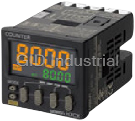
OMRON H7CZ

Description
Omron H7CZ Counters/Timer Modules-Multifunction Preset Counter
Part Number
H7CZ
Price
Request Quote
Manufacturer
OMRON
Lead Time
Request Quote
Category
Counter/Timer Modules
Specifications
Digits
6 digits
External connections
8-pin socket
Input mode
Increment, Decrement
Maximum counting speed
30 Hz or 10 kHz (switchable) (ON/OFF ratio 1:1)
Mounting method
Flush mounting or surface mounting
Operating voltage fluctuation range
85% to 110% of rated supply voltage (12 to 24 VDC: 90% to 110%)
Power consumption
Approx. 9.4 VA at 100 to 240 VAC,
Power supply voltage
100 to 240 VAC, 50/60 Hz
Sensor waiting time
290 ms max.
Features
- Character height of 10 mm for better readability.
- Key protection
- Operation is simplified by the Up Key for each digit.
- Power supply circuit and input circuits are isolated inside the Counter.
- Set value limit function prevents unexpected operation of output devices caused by setting mistakes.
- Waterproof, dust-proof structure
Datasheet

Extracted Text
New Product Digital Counter H7CZ Easy to Use and Easy to Read. Basic Features • Character height of 10 mm for better readability. Operation is simplified by the Up Key for each digit. Safety and Reliability Power supply circuit and input ci rcuits are isolated inside the Counter. Set value limit function prevents unexpected operation of output devices caused by setting mistakes. Output counter function helps in managing the service life of the Counter or the load. Other Features Waterproof, dust-proof struct ure (UL508 Type 4X and IP66). Key protection. Refer to Safety Precautions on page 17. Features Set Value Limit Basic Features You can set an upper limit for the set value to prevent unexpected Better Readability operation of output devices caused by setting mistakes. Character Height of 10 mm with a Wide Viewing Angle. Easy to read from the top, bottom, and sides. Clear 10 mm (actual size) Confirmation Setting the upper limit of the set value enables worry-free operation. The Easiest Operation Operation is simplified by the Up Key for No overflow each digit. For 1,000 pieces Output Counter The output counter counts the number of times the output turns ON Safety and Reliability (alarms can be displayed and the count can be monitored in increments of 1,000 operations). This counter is useful in managing Isolated Power Supply and Input Circuits the service life of the Counter or the load. Power supply circuit and input circuits are isolated inside the Counter. Other Features Previous non-isolated counters had wiring restrictions and could be damaged if wired incorrectly. The H7CZ removes these worries. Waterproof, Dust-proof Structure (UL508 Type 4X and IP66) Worry-free application is possible in locations subject to water. Note: When the Y92S-29 Waterproof Packing is used. Key Protection Select from any of seven protection patterns. Use the best one for the application. 1 H7CZ Model Number Structure Model Number Legend H7CZ-L@@ 12 1. External connections 2. Supply voltage Symbol Meaning Symbol Meaning 8 8-pin socket None 100 to 240 VAC at 50/60 Hz D1 12 to 24 VDC/24 VAC at 50/60 Hz Ordering Information List of Models External Display Power supply Type Configuration Settings Outputs Model connections digits voltage 100 to 240 VAC H7CZ-L81-stage preset H7CZ 8-pin socket 1-stage 6 digits Contact output (SPDT) counter 12 to 24 VDC/24 VAC H7CZ-L8D1 Note: The functions that are provided depend on the model. Check detailed specifications before ordering. Accessories (Order Separately) Soft Cover Model Page Y92A-48F1 9 Hard Cover Model Page Y92A-48 9 Flush Mounting Adapter Model Page Y92F-30 9 Waterproof Packing Model Page Y92S-29 9 Connection Sockets Model Type Remarks Page P2CF-08 Front-connecting Socket --- Round crimp terminals cannot be used on P2CF-08-E Front-connecting Socket (Finger-safe Type) Finger-safe Sockets. 10 Use forked crimp terminals. A Y92A-48G Terminal Cover can be used with P3G-08 Back-connecting Sockets the Socket to create a finger-safe construction. Terminal Covers for P3G-08 Back-connecting Socket Model Page Y92A-48G 10 2 H7CZ H7CZ Multifunction Preset Counter Specifications Ratings Item Models H7CZ-L8 H7CZ-L8D1 Configuration 1-stage preset counter *1 Power supply voltage 100 to 240 VAC, 50/60 Hz 24 VAC, 50/60 Hz or 12 to 24 VDC Operating voltage fluctuation Ratings 85% to 110% of rated supply voltage (12 to 24 VDC: 90% to 110%) range Power consumption Approx. 9.4 VA at 100 to 240 VAC, Approx. 7.2 VA/4.7 W at 24 VAC/12 to 24 VDC Mounting method Flush mounting or surface mounting External connections 8-pin socket Degree of protection IEC IP66, UL508 Type 4X (indoors) for panel surface only and only when Y92S-29 Waterproof Packing is used. Input signals Count, Reset Maximum counting speed 30 Hz or 10 kHz (switchable) (ON/OFF ratio 1:1) Input mode Increment, Decrement Output mode N, F, C, R, K-1, P, Q, and A. Counter One-shot output time 0.01 to 99.99 s External (minimum reset signal width: 1 ms or 20 ms, selectable), Manual, and Automatic reset (internal according Reset system to C, R, P, and Q mode operation) Prescaling function Yes (0.001 to 99.999) Decimal point adjustment Yes (rightmost 3 digits) Sensor waiting time 290 ms max. (Control output is turned OFF and no input is accepted during sensor waiting time.) No-voltage inputs: ON impedance: 1 kΩ max. (Leakage current: 12 mA at 0 Ω) Input method ON residual voltage: 3 V max. OFF impedance: 100 kΩ min. 3 A at 250 VAC/30 VDC, resistive load (cosφ=1), Minimum applied load: 10 mA at 5 VDC (failure level: P, reference Control output value) LCD Character height *2 Display Count value: 10 mm Set value: 6 mm 6 digits Digits −99999 to 999999 (−5 digits to +6 digits) Memory backup EEPROM (overwrites: 100,000 times min.) that can store data for 10 years min. Operating temperature range −10 to 55°C (−10 to 50°C if Counters are mounted side by side) (with no icing or condensation) Storage temperature range −25 to 70°C (with no icing or condensation) Operating humidity range 25% to 85% Front panel color Light gray (5Y7/1) *1. Do not use the output from an inverter as the power supply.The ripple must be 20% maximum for DC power. *2. The display is lit only when the power is ON. Nothing is displayed when power is OFF. 3 H7CZ Characteristics Life-test Curve (Reference 100 MΩ min. (at 500 VDC) between current-carrying terminals and exposed non- Insulation resistance current-carrying metal parts, and between non-continuous contacts Values) 2,000 VAC, 50/60 Hz for 1 min between current-carrying metal parts and non-current- Resistive load carrying metal parts 2,000 VAC, 50/60 Hz for 1 min between power supply and input circuit (1,000 VAC for 1,000 Dielectric strength 24 VAC/12 to 24 VDC) 1,000 VAC, 50/60 Hz for 1 min between control output, power supply, and input circuit 700 (2,000 VAC) 1,000 VAC, 50/60 Hz for 1 min between non-continuous contacts 500 3.0 kV between power terminals (1.0 kV for models with 24 VAC/12 to 24 VDC) Impulse withstand voltage 4.5 kV between current-carrying terminals and exposed non-current-carrying metal 300 parts (1.5 kV for models with 24 VAC/12 to 24 VDC) 30 VDC (cosφ=1) ±1.5 kV between power terminals Noise immunity ±600 V between input terminals Square-wave noise by noise simulator (pulse width: 100 ns/1 µs, 1-ns rise) Malfunction: 8 kV 250 VAC (cosφ=1) Static immunity 100 Destruction: 15 kV Destruction 10 to 55 Hz with 0.75-mm single amplitude each in three directions for 2 h each Vibration 70 resistance Malfunction 10 to 55 Hz with 0.35-mm single amplitude each in three directions for 10 min each 50 2 Destruction 300 m/s each in three directions 01 2 3 4 Shock re- 2 sistance Malfunction 100 m/s each in three directions Load current (A) Mechanical: 10,000,000 operations min. Inductive load Life expectancy Electrical: 100,000 operations min. (3 A at 250 VAC, resistive load, ambient * temperature condition: 23°C) 1,000 Weight Approx. 100 g (Counter only) 700 * Refer to the Life-test Curve. 500 Applicable Standards * cULus (or cURus): UL508/CSA C22.2 No. 14 300 Approved EN 61010-1 (IEC 61010-1): Pollution degree 2/overvoltage category II 30 VDC (L/R=7 ms) safety B300 PILOT DUTY standards 1/4 HP 120 VAC, 1/3 HP, 240 VAC, 3 A resistive load VDE0106/P100 (finger protection) (EMI) EN61326 100 Emission Enclosure: EN 55011 Group 1 class A 250 VAC (cosφ=1) Emission AC mains: EN 55011 Group 1 class A 70 (EMS) EN61326 Immunity ESD: EN 61000-4-2: 4 kV contact discharge; 50 01 2 3 4 8 kV air discharge Immunity RF-interference: EN 61000-4-3: 10 V/m (Amplitude-modulated, 80 MHz to 1 GHz); Load current (A) EMC 10 V/m (Pulse-modulated, 900 MHz ±5 MHz) A current of 0.15 A max. can be switched at Immunity Conducted Disturbance: EN 61000-4-6: 10 V (0.15 to 80 MHz) 125 VDC (cosφ=1) and current of 0.1 A max. can Immunity Burst: EN 61000-4-4: 2 kV power-line; 1 kV I/O signal-line be switched if L/R=7 ms. In both cases, a life of Immunity Surge: EN 61000-4-5: 1 kV line to lines (power and output lines); 100,000 operations can be expected. 2 kV line to ground (power and output lines) Immunity Voltage Dip/Interruption: EN 61000-4-11: 0.5 cycle, 100% (rated voltage) * The following safety standards apply to H7CZ. cUL (Listing): Applicable when an OMRON P2CF(-E) Socket is used. cUR (Recognition): Applicable when any other socket is used. I/O Functions *1 Using as a Counter Reads counting signals. Count Increment and decrement inputs accepted. *2 Inputs Resets present value and outputs. Reset Counting cannot be performed during reset input. Reset indicator is lit while reset input is ON. Outputs OUT Outputs signals according to the specified output mode when a set value is reached. *1. For information on operation of I/O functions, refer to page 14 and page 15. *2. In elapsed time mode, the present value returns to 0; in remaining time mode, the present value returns to the set value. The following table shows the delay from when the reset signal is input until the output is turned OFF. (Reference values) Minimum reset signal width Output delay time 1 ms 0.8 to 1.2 ms 20 ms 15 to 25 ms 4 3 3 No. of operations ( 10 ) No. of operations ( 10 ) × × H7CZ Connections Block Diagram Input Circuits Count and Reset Input (Basic insulation) Power supply Output circuit circuit No-voltage Inputs (NPN Inputs) (Basic insulation) (Basic insulation) Display circuit +14V Internal Input circuits control circuit Key switch 1 kΩ circuit Internal IN circuit Terminal Arrangement Confirm that the power supply meets specifications before use. H7CZ-L8/L8D1 1-stage Contact Output Internal circuit Count Reset Contact Output 0V (−) (+) Input Connections The inputs of the H7CZ-L8@ are no-voltage (short-circuit or open) inputs. No-voltage Inputs (NPN Inputs) Open Collector Voltage Output Contact Input DC Two-wire Sensor PLC or Sensor sensor 134 134 134 134 Note: Operates with transistor ON. Note: Operates with transistor ON. Note: Operates with relay ON. Note: Operates with transistor ON. No-voltage Input Signal Levels Short-circuit level (transistor ON) • Residual voltage: 3 V max. Applicable Two-wire Sensor Impedance when O N: 1 kΩ max. Leakage current: 1.5 mA max. No-contact input (The leakage current is approx. 12 mA when the impedance is 0 Ω.) Switching capacity: 5 mA min. Open level (transistor OFF)Residual voltage: 3 VDC max. Impedance when OFF: 100 k Ω min.Operating voltage: 10 VDC Contact input Use contacts which can adequately switch 5 mA at 10 V. Note: The DC voltage must be 30 VDC max. 5 0 V for inputs Reset input Count input 0 V for inputs Reset input Count input 0 V for inputs Reset input Count input 0 V for inputs Reset input Count input H7CZ Nomenclature Display Section Operation Keys 4 1. Key Protect Indicator 6. Mode Key (Changes modes and setting items.) 1 2. Control Output Indicator 2 5 7. Reset Key 3 3. Reset Indicator 1 6 6 8. Up Keys to 4. Present Value (Main Display) 8 7 (Character height: 10 mm) Switches 5. Set value (Sub-display) 6th digit 1st digit (Character height: 6 mm) 9. Key-protect Switch (Default setting) OFF ON 9 (Disable) (Enable) Character Size Character Size for Main Display for Sub-display 10 mm 6 mm Dimensions (Unit: mm) Counters Panel Cutouts H7CZ-L8/-L8D1 (Flush Mounting/Surface Mounting Models) Panel cutouts are as shown below. (according 14.2 to DIN43700). 6 63.7 48 × 48 60 min. + 0.6 45 0 44.8×44.8 +0.6 45 0 15 min. 60 min. Dimensions with Flush Mounting Adapter Note: 1. The mounting panel thickness H7CZ-L8/-L8D1 (Adapter and Waterproof Packing Ordered Separately) should be 1 to 5 mm. Y92S-29 (order separately) Panel Y92F-30 (order separately) 2. To allow easier operation, it is P3G-08 (order Waterproof Packing Flush Mounting Adapter recommended that Adapters be separately) mounted so that the gap between Back-connecting Socket sides with hooks is at least 15 mm (i.e., with the panel cutouts separated by at least 60 mm). 3. It is possible to horizontally mount 58 (51) Timers side by side. Attach the Flush Mounting Adapters so that the surfaces without hooks are on the sides of the Timers. If they are mounted side-by-side, water- resistance will be lost. 48 7.5 84.8 n Units mounted side by side A +1 A=(48n−2.5) −0 With Y92A-48F1 attached. +1 A={48n−2.5+(n−1)×4} −0 With Y92A-48 attached. +1 A=(51n−5.5) −0 Dimensions with Front Connecting Socket H7CZ * -L8@ 90 92.3 P2CF-08(-E) (order separately) Front Connecting Socket * These dimensions depend on the kind of DIN Track. (Reference value) 6 H7CZ Accessories (Order Separately) Note: Depending on the operating environment, the condition of resin products may deteriorate, and may shrink or become harder. Therefore, it is recommended that resin products are replaced regularly. Waterproof Packing Soft Cover Hard Cover Order this Waterproof Packing Y92S-29 Y92A-48F1 Y92A-48 separately if it is required. The Waterproof Packing can be used to achieve IP66 protection. The Waterproof Packing will deteriorate, harden, and shrink depending on the application environment. To ensure maintaining the Protecting the Counter in Environments Subject to Oil IP@6, UL Type 4X waterproof level, periodically replace the The H7CZ's panel surface is water-resistive (conforming to IP@6, Waterproof Packing. The periodic replacement period will depend on UL Type 4X) and so even if drops of water penetrate the gaps the application environment. You must confirm the proper between the keys, there will be no adverse effect on internal circuits. replacement period. Use 1 year or less as a guideline. If the If, however, there is a possibility of oil being present on the Waterproof Packing is not replaced periodically, the waterproof level operator's hands, use the Soft Cover. The Soft Cover ensures will not be maintained. It is not necessary to mount the Waterproof protection equivalent to IP54F against oil. Do not, however, use the Packing if waterproof construction is not required. H7CZ in locations where it would come in direct contact with oil. Flush Mounting Adapter Y92F-30 Order this Flush Mounting Adapter separately if it is required. 7 H7CZ Connection Sockets Front Connecting Socket Terminal arrangement Mounting hole Model Dimensions and internal connections dimensions P2CF-08 20.3 max. 50 max. Two, 4.5-dia. holes 70 max. 35.4 4 6 5 4 3 Two, M4 or 4.5-dia. holes 7.8 Eight, M3.5 x 7.5 sems screws 3 4.5 P2CF-08-E 21.5 max. ±0.2 40 (Finger Safe Terminal) 20.3 50 max. Note: The Socket can ±0.2 40 19 7 8 1 2 also be mounted to DIN track. (Top View) 65 43 3 Two, 4.5-dia. holes P2CF-08-E 1.3 70 max. 35.4 10A250VAC RESISTIVE 78 12 4 7.8 Eight, M3.5 x 7.5 set screws 5 4.5 Note: Round crimp terminals cannot be used on Finger-safe Sockets. Use forked crimp terminals. Back-connecting Sockets Terminal arrangement Model Dimensions and internal connections P3G-08 27 dia. 3 4 5 6 45 2 1 8 7 (Bottom View) 45 4.9 17 Note: A Y92A-48G Terminal Cover can be used with the Socket to create a finger-safe construction. Terminal Covers for P3G-08 Back-connecting Socket Model Dimensions Y92A-48G Twelve, 6.4-dia. holes 34 47.7 × 47.7 48 × 48 Y92A-48G UP P C 16.5 24.6 27.6 47.4 Note: The Terminal Cover can be used with a Back-mounting Socket (P3G-08) to create a finger-safe construction. 8 H7CZ Optional Products for Track Mounting Mounting Track ±0.15 7.3 PFP-100N 4.5 PFP-50N ±0.3 ±0.15 35 27 15 (5)* 1 15 25 10 25 25 10 25 1,000 (500)* * The values shown in parentheses are for the PFP-50N. 16 Mounting Track PFP-100N2 4.5 ±0.3 35 27 24 29.2 1 1.5 15 25 10 25 25 10 25 15 1,000 10 End Plate 6.2 1.8 PFP-M M4 × 8 pan head screw 1 50 35.5 35.3 1.8 11.5 10 1.3 M4 spring washer 4.8 16 Spacer 5 12 PFP-S 34.8 44.3 16.5 Note: Order Spacers in increments of 10. 9 H7CZ Operating Procedures Setting Procedure Guide Change to Function Setting Mode. Power ON For details on operations and display in run mode, refer to page 13. *1 3 s min. The display depends on the selected configuration. Function Run mode setting mode *2 3 s min. *1. If the mode is switched to the function setting mode during operation, operation will continue. *2. Changes made to settings in function setting mode are enabled for the first time when the mode is changed to run mode. Also, when settings are changed, the counter is reset (present value initialized and output turned OFF) on returning to run mode. The characters displayed in reverse video are the default settings. Set the input mode using the U Key. Input mode (CNTM) down up (UP) (DOWN) Set the output mode using the U Key. Output mode (OUTM) f cr k-1 p q a n (N) (F) (C) (R) (K-1) (P) (Q) (A) Output Set each digit using the individual U Key. time (OTIM) 0.01 0.50 99.99 (0.01 s)(0.50 s) (99.99 s) Note: Displayed only when the output mode is C, R, K-1, P, Q, or A. Set the counting speed using the U Key. Counting speed (CNTS) 30hz (30 Hz) (5 kHz) Set the Reset input signal width using the U Key. Reset input signal width 20ms 1ms (IFLT) (20 ms) (1 ms) Set the decimal point position using the U Key. Decimal point position (DP) (One digit after (Two digits after (Three digits after (No decimal decimal point) decimal point) decimal point) point) Set each digit using the individual U Key. Prescale value 0.001 1.000 99.999 (PSCL) (0.001) (1.000) (99.999) From next page To next page 10 Function Setting Mode H7CZ To previous From previous page page Set value Set each digit using the individual U Key. upper limit (SL-H) 1 999999 (1) (999999) Key protect Set the key protect level using the U Key. level (KYPT) kp-1 kp-2 kp-3 kp-4 kp-5 kp-6 kp-7 (KP-1) (KP-2) (KP-3) (KP-4) (KP-5) (KP-6) (KP-7) *3 Output ON count alarm set value/monitor *3. Set each digit using the individual U Key. value Output ON count 0 9999 alarm set (0 × 1000 times) (9999 × 1000 times) value Output ON count monitor Note: The monitor value is only displayed. It cannot be set. value 11 Function Setting Mode H7CZ Explanation of Functions Set Value Upper Limit (sl-h) Set the upper limit for the set value when it is set in run mode. Input Mode (cntm) The setting can be made from 1 to 999999 for 6-digit models. Set increment mode (UP) or decrement mode (DOWN) as the input mode. Key Protect Level (kypt) Set the key protect level. Output Mode (outm) Refer to Key Protect Level on page 16. Set the way that control output for the present value is output. The possible settings are N, F, C, R, K-1, P, Q, and A. Output ON Count Alarm Set Value (on-a) Set the alarm value for the output ON count. One-shot Output Time (otim) The limit can be set to between 0 × 1000 (0 times) and 9999 × 1000 Set the one-shot output time (0.01 to 99.99 s) for control output. (9,999,000 times). Only the underlined values are set. The alarm will One-shot output can be used only when C, R, K-1, P, Q, or A is be disabled if 0 is set. selected as the output mode. If the total ON count of the output exceeds the alarm set value, e3 Counting Speed (cnts) will be displayed on the Timer to indicate that the output ON count Set the maximum counting speed (30 Hz/5 kHz) for count inputs. alarm value was exceeded. Refer to Self-diagnostic Function on page 16 for information on the e3 display. Reset Input Signal Width (iflt) Set the reset input signal width (20 ms/1 ms) for reset inputs. Output ON Count Monitor Value (on-c) If contacts are used for the input signal, set the input signal width to The monitor value is only displayed. It cannot be set. 20 ms. Processing to eliminate chattering is performed for this setting. The output ON count will be 1,000 times the displayed value. Decimal Point Position (dp) Decide the decimal point position for the present value. Prescale Value (pscl) Pulses input to the counter are converted according to the specified prescale value. (Setting range: 0.001 to 99.999 for 6-digit models.) Example: To display the feed distance for systems that output 25 pulses for a feed length of 0.5 m in the form @@.@@ m: 1. Set the decimal point position to 2 decimal places. 2. Set the prescale value to 0.02 (0.5 ÷ 25). 0.5 m 25 pulses Encoder Observe the following points when setting a prescale value. Set the set value to a value less than {Maximum countable value − Prescale value}. Example: If the prescale value is 1.25 and the counting range is 0.000 to 999.999, set the set value to a value less than 998.749 (= 999.999 − 1.25). If the set value is set to a value greater than this, output will not turn ON. Output will turn ON, however, if a present value overflow occurs (FFFFFF). Note: If the prescale value setting is incorrect, a counting error will occur. Check that the settings are correct before using this function. 12 H7CZ Operation in Run Mode Set values for each digit as required using the U Key. Present value Set value Present Value Shows the present count value. Set Values Set the set values. When the present value reaches the set value, a signal is output according to the specified output mode. Input Modes and Present Value I/O Functions for Counter Operation UP (Increment) Mode DOWN (Decrement) Mode H H Count input Count input L L n n−1 4 n−2 3 Present value Present value n−3 2 n−4 1 0 0 0 * Counting starts when the count input is turned ON after turning ON the power. Note: 1. The meaning of the H and L symbols in the tables is explained below. Symbol No-voltage input Input method (NPN input) H Short-circuit L Open 13 H7CZ Input/Output Mode Settings (The one-shot output time can be set in the range 0.01 to 99.99s.) Self-holding One-shot output Input mode Operation after count completion UP DOWN Reset 999999 The outputs and present Set value N value display are held until reset is input. 0 OUT Reset 999999 The present value Set value display continues to F increase/decrease. The outputs are held until 0 reset is input. OUT Reset As soon as the count reaches SV, the present 999999 value display returns to the reset start status. Output Set value The present value display mode C does not show the setting present value upon count- 0 up. The outputs repeat one- shot operation. OUT Reset 999999 The present value display returns to the Set value reset start status after R the one-shot output time. 0 The outputs repeat one- shot operation. OUT Reset 999999 The present value Set value K-1 display continues to increase/decrease. 0 OUT 14 H7CZ (The one-shot output time can be set in the range 0.01 to 99.99s.) Self-holding One-shot output Input mode Operation after count completion UP DOWN Reset The present value display does not change during the 999999 one-shot output time Set value period, but the actual P count returns to the reset start status. 0 The output will return to one-shot mode. The outputs repeat OUT one-shot operation. Reset The present value continues to increase/ 999999 decrease for the one- shot output time, but Output Set value mode returns to the reset Q setting start status after the 0 one-shot output time has elapsed. The outputs repeat one-shot operation. OUT Reset 999999 The present value Set value display and OUT self- A holding output is held until reset is input. 0 OUT Note: 1. When the present value reaches 999999, it returns to 0. 2. Counting cannot be performed during reset input. 3. If reset is input while one-shot output is ON, one-shot output turns OFF. 4. If there is power failure while output is ON, output will turn ON again when the power supply has recovered. For one-shot output, output will turn ON again for the duration of the output time setting once the power supply has recovered. 5. Do not use the counter function in applications where the count may be completed (again) while one-shot output is ON. 6. The setting range is 0 to 999,999. 15 H7CZ Key Protect Level It is possible to prevent setting errors by prohibiting the use of certain operation keys by specifying the key protect level (KP-1 to KP-7) when the key-protect switch is set to ON. The key protect level is set in the function setting mode. The key protect indicator is lit when the key-protect switch is ON. OFF* ON (Disabled) (Enabled) * Factory-set to OFF Key protect indicator Details Level Description Changing modes* Reset Key Up Keys KP-1 Invalid Valid Valid (default setting) KP-2 Invalid Invalid Valid KP-3 Invalid Valid Invalid KP-4 Invalid Invalid Invalid KP-5 Invalid Invalid Invalid KP-6 Invalid Valid Valid KP-7 Invalid Invalid Valid * Changing mode to function setting mode. Self-diagnostic Function The following displays will appear if an error occurs. Main display Sub-display Description Output status Correction method Set value after reset Either press the Reset Key or turn *1 *2 ----- No change Present value underflow No change No change ON reset input. Either press the Reset Key or turn *1 fffff No change Present value overflow No change No change ON reset input. Either press the Reset Key or e1 Not lit CPU error OFF No change reset the power supply. e2 Not lit Memory error (RAM) OFF Turn ON the power again. No change *3 e2 sum Memory error (EEPROM) OFF Reset Key Factory setting *4 *5 e3 No change Output Counter Overflow No change Reset Key No change *1. Display flashes.(1-second cycles) *2. This occurs if the present value or total count value falls below −99999. *3. This includes times when the life of the EEPROM has expired. *4. The normal display and e3 will appear alternately. When the Reset Key is pressed, e3 will not be displayed even if the alarm set value is exceeded. (Monitoring is possible, however, because the counter will continue without the output ON count being cleared.) *5. This is displayed if the alarm value setting for either of the two outputs is exceeded if a model with two outputs is used.The total ON count will not be cleared by using the Reset Key. 16 H7CZ Safety Precautions for All H7CZ Series (Common) Internal elements may be destroyed if a voltage outside the rated CAUTION voltage range is applied. Be sure that polarity is correct when wiring the terminals. Do not allow pieces of metal, wire clippings, or fine Separate the Counter from sources of noise, such as devices with metallic shavings or fillings from installation to enter input signals from power lines carrying noise, and wiring for I/O the product. Doing so may occasionally result in signals. electric shock, fire, or malfunction. Do not connect more than two crimp terminals to the same terminal. Minor injury due to explosion may occasionally occur. Up to two wires of the same size and type can be inserted into a Do not use the Counter where subject to flammable or single terminals. explosive gas. Use the specified wires for wiring. Applicable Wires: AWG 18 to AWG 22, solid or twisted, copper Fire may occasionally occur. Tighten the terminal Install a switch or circuit breaker that allows the operator to screws to the rated torque. immediately turn OFF the power, and label it to clearly indicate its P2CF Socket terminals: 4.4 lb-in (0.5 N·m) function. Approximately 14 V is output from the input terminals. Use a sensor that contains a diode. Minor injury due to electric shock may occasionally Sensor occur. Do not touch any of the terminals while power Diode is being supplied. Be sure to mount the terminal cover after wiring. 0 V Input Use a switch, relay, or other contact so that the rated power supply The life expectancy of the output relay varies voltage will be reached within 0.1 seconds. If the power supply considerably according to its usage. Use the output voltage is not reached quickly enough, the Counter may relay within its rated load and electrical life malfunction or outputs may be unstable. expectancy. If the output relay is used beyond its life Use a switch, relay, or other contact to turn the power supply OFF expectancy, its contacts may become fused or there may be a instantaneously. Outputs may malfunction and memory errors may risk of fire. Also, be sure that the load current does not exceed occur if the power supply voltage is decreased gradually. the rated load current and when using a heater, be sure to use a When changing the set value during operation, because the H7CZ thermal switch in the load circuit. uses a constant read-in system, output will turn ON if the set value is equal to the present value. Minor electric shock, fire, or malfunction may When changing the comparison value during operation, because occasionally occur. Do not disassemble, modify, or the H7CZ uses a constant read-in system, the output status will repair the Counter or touch internal components. change if the comparison value is changed to a value on the other side of the present value. Do not use organic solvents (such as paint thinners or benzine), strong alkali, or strong acids. They will damage the external finish. Precautions for Safe Use Confirm that indications are working normally, including the LCD. The panel surface of the H7CZ is water-resistant (conforming to The indicator, LCD, and resin parts may deteriorate more quickly NEMA4, IP66, UL Type 4X (Indoor Use Only). To protect the depending on the application environment, preventing normal internal circuits from water penetration through the space between indications. Periodic inspection and replacement are required. the H7CZ and operating panel, waterproof packing is included. The waterproof packing may deteriorate, shrink, or harden Attach the Y92F-30 Adapter with sufficient pressure with the depending on the application environment. Periodic inspection and reinforcing screws so that water does not penetrate the panel. replacement are required. 0.5 to 1 mm It is recommended that the space between the screw head and the Adapter be 0.5 to 1 mm. When mounting the Counter to a panel, tighten the two mounting screws alternately, a little at a time, so as to keep them at an equal tightness. If the panel screws are tightened unequally, water may enter the panel. Store the Counter at the specified temperature. If the Counter has been stored at a temperature of less than −10°C, allow the Counter to stand at room temperature for at least 3 hours before use. Mounting the Counter side-by-side may reduce the life expectancies of internal components. Use the Counter within the specified ranges for the ambient operating temperature and humidity. Do not use in the following locations: Locations subject to sudden or extreme changes in temperature. Locations where high humidity may result in condensation. Do not use the Counter outside of the rated ranges for vibration, shock, water exposure, and oil exposure. Do not use this Counter in dusty environments, in locations where corrosive gasses are present, or in locations subject to direct sunlight. Install the Counter well away from any sources of static electricity, such as pipes transporting molding materials, powders, or liquids. 17 H7CZ Precautions for Correct Use Conformance to EN/IEC Standards • An inrush current of approx. 10 A will flow for a short time when the When conforming to EMC standards, refer to the information power supply is turned ON. If the capacity of the power supply is provided in this datasheet for cable selection and other conditions. not sufficient, the Counter may not start. Be sure to use a power This is a class A product. In resi dential areas it may cause radio supply with sufficient capacity. interference, in which case the user may be required to take Maintain voltage fluctuations in the power supply within the adequate measures to reduce interference. specified operating voltage range.Basic insulation is provi ded between power supply and input When turning the power ON and OFF, input signal reception is terminals, between power supply and output terminals, and possible, unstable, or impossible as shown in the diagram below. between input and output terminals. When double insulation or reinforced insulation is required, apply double insulation or reinforced insulation as defined in IEC 60664 Power ON supply OFF that is suitable for the maximum operating voltage with clearances 200 ms 0 to 90 ms 5 ms 0 to 1 s or solid insulation. Connect the input and output terminals to devices that do not have Input Impossible Unstable Possible Unstable Impossible any exposed charged parts. Inrush current generated by turn ing ON or OFF the power supply may deteriorate contacts on the power supply circuit. Turn ON or OFF to a device with the rated current of more than 10 A. If the prescale value setting is inco rrect, a counting error will occur. Check that the settings are correct before using this function. Make sure that all settings ar e appropriate for the application. Unexpected operation resulting in property damage or accidents may occur if the settings are not appropriate. Do not leave the Counter for l ong periods at a high temperature with output current in the ON state. Doing so may result in the premature deterioration of internal components (e.g., electrolytic capacitors). EEPROM is used as backup memory when the power is interrupted. The write life of the EEPROM is 100,000 writes. The EEPROM is written at the following times: When the power supply is turned OFF When switching from Configurat ion Selection Mode or Function Setting Mode to Run Mode Dispose of the product according to local ordinances as they apply. 18 Warranty and Application Considerations Read and Understand This Catalog Please read and understand this catalog before purchasing the products. Please consult your OMRON representative if you have any questions or comments. Warranty and Limitations of Liability WARRANTY OMRON's exclusive warranty is that the products are free from defects in materials and workmanship for a period of one year (or other period if specified) from date of sale by OMRON. OMRON MAKES NO WARRANTY OR REPRESENTATION, EXPRESS OR IMPLIED, REGARDING NON-INFRINGEMENT, MERCHANTABILITY, OR FITNESS FOR PARTICULAR PURPOSE OF THE PRODUCTS. ANY BUYER OR USER ACKNOWLEDGES THAT THE BUYER OR USER ALONE HAS DETERMINED THAT THE PRODUCTS WILL SUITABLY MEET THE REQUIREMENTS OF THEIR INTENDED USE. OMRON DISCLAIMS ALL OTHER WARRANTIES, EXPRESS OR IMPLIED. LIMITATIONS OF LIABILITY OMRON SHALL NOT BE RESPONSIBLE FOR SPECIAL, INDIRECT, OR CONSEQUENTIAL DAMAGES, LOSS OF PROFITS, OR COMMERCIAL LOSS IN ANY WAY CONNECTED WITH THE PRODUCTS, WHETHER SUCH CLAIM IS BASED ON CONTRACT, WARRANTY, NEGLIGENCE, OR STRICT LIABILITY. In no event shall the responsibility of OMRON for any act exceed the individual price of the product on which liability is asserted. IN NO EVENT SHALL OMRON BE RESPONSIBLE FOR WARRANTY, REPAIR, OR OTHER CLAIMS REGARDING THE PRODUCTS UNLESS OMRON'S ANALYSIS CONFIRMS THAT THE PRODUCTS WERE PROPERLY HANDLED, STORED, INSTALLED, AND MAINTAINED AND NOT SUBJECT TO CONTAMINATION, ABUSE, MISUSE, OR INAPPROPRIATE MODIFICATION OR REPAIR. Application Considerations SUITABILITY FOR USE OMRON shall not be responsible for conformity with any standards, codes, or regulations that apply to the combination of products in the customer's application or use of the products. Take all necessary steps to determine the suitability of the product for the systems, machines, and equipment with which it will be used. Know and observe all prohibitions of use applicable to this product. NEVER USE THE PRODUCTS FOR AN APPLICATION INVOLVING SERIOUS RISK TO LIFE OR PROPERTY WITHOUT ENSURING THAT THE SYSTEM AS A WHOLE HAS BEEN DESIGNED TO ADDRESS THE RISKS, AND THAT THE OMRON PRODUCTS ARE PROPERLY RATED AND INSTALLED FOR THE INTENDED USE WITHIN THE OVERALL EQUIPMENT OR SYSTEM. Disclaimers PERFORMANCE DATA Performance data given in this catalog is provided as a guide for the user in determining suitability and does not constitute a warranty. It may represent the result of OMRON's test conditions, and the users must correlate it to actual application requirements. Actual performance is subject to the OMRON Warranty and Limitations of Liability. CHANGE IN SPECIFICATIONS Product specifications and accessories may be changed at any time based on improvements and other reasons. Consult with your OMRON representative at any time to confirm actual specifications of purchased product. DIMENSIONS AND WEIGHTS Dimensions and weights are nominal and are not to be used for manufacturing purposes, even when tolerances are shown. ALL DIMENSIONS SHOWN ARE IN MILLIMETERS. To convert millimeters into inches, multiply by 0.03937. To convert grams into ounces, multiply by 0.03527. OMRON Corporation Industrial Automation Company Authorized Distributor: Tokyo, JAPAN Contact: www.ia.omron.com Regional Headquarters OMRON EUROPE B.V. OMRON ELECTRONICS LLC Wegalaan 67-69-2132 JD Hoofddorp One Commerce Drive Schaumburg, The Netherlands IL 60173-5302 U.S.A. Tel: (31)2356-81-300/Fax: (31)2356-81-388 Tel: (1) 847-843-7900/Fax: (1) 847-843-7787 © OMRON Corporation 2009 All Rights Reserved. OMRON (CHINA) CO., LTD. OMRON ASIA PACIFIC PTE. LTD. In the interest of product improvement, No. 438A Alexandra Road # 05-05/08 (Lobby 2), Room 2211, Bank of China Tower, specifications are subject to change without notice. Alexandra Technopark, 200 Yin Cheng Zhong Road, CSM_7_1_1011 Singapore 119967 PuDong New Area, Shanghai, 200120, China Printed in Japan Tel: (65) 6835-3011/Fax: (65) 6835-2711 Tel: (86) 21-5037-2222/Fax: (86) 21-5037-2200 Cat. No. M082-E1-01 0709
Frequently asked questions
How does Industrial Trading differ from its competitors?

Is there a warranty for the H7CZ?
Which carrier will Industrial Trading use to ship my parts?
Can I buy parts from Industrial Trading if I am outside the USA?
Which payment methods does Industrial Trading accept?
Why buy from GID?

Quality
We are industry veterans who take pride in our work

Protection
Avoid the dangers of risky trading in the gray market

Access
Our network of suppliers is ready and at your disposal

Savings
Maintain legacy systems to prevent costly downtime

Speed
Time is of the essence, and we are respectful of yours
Related Products
Omron H7CX-A114D1-N Counters/Timer Modules-48*48mm (1/16 DIN), 11-Pin Socket, 4 Digits, 1-Stage, Sup...
Omron H7CX-A114-N Counter/Timer Modules-48*48mm (1/16 DIN), 11-Pin Socket, 4 Digits, 1-Stage
Omron H7CX-A114S-N Counter/Timer Modules-48*48mm (1/16 DIN), 11-Pin Socket, 4 Digits, 1-Stage, Solid...
Request a Quote

The quote request has been received
Close

Facing challenges or have inquiries? Feel free to contact us!
Call Us +1-469-283-2440
What they say about us
FANTASTIC RESOURCE
One of our top priorities is maintaining our business with precision, and we are constantly looking for affiliates that can help us achieve our goal. With the aid of GID Industrial, our obsolete product management has never been more efficient. They have been a great resource to our company, and have quickly become a go-to supplier on our list!
Bucher Emhart Glass
EXCELLENT SERVICE
With our strict fundamentals and high expectations, we were surprised when we came across GID Industrial and their competitive pricing. When we approached them with our issue, they were incredibly confident in being able to provide us with a seamless solution at the best price for us. GID Industrial quickly understood our needs and provided us with excellent service, as well as fully tested product to ensure what we received would be the right fit for our company.
Fuji
HARD TO FIND A BETTER PROVIDER
Our company provides services to aid in the manufacture of technological products, such as semiconductors and flat panel displays, and often searching for distributors of obsolete product we require can waste time and money. Finding GID Industrial proved to be a great asset to our company, with cost effective solutions and superior knowledge on all of their materials, it’d be hard to find a better provider of obsolete or hard to find products.
Applied Materials
CONSISTENTLY DELIVERS QUALITY SOLUTIONS
Over the years, the equipment used in our company becomes discontinued, but they’re still of great use to us and our customers. Once these products are no longer available through the manufacturer, finding a reliable, quick supplier is a necessity, and luckily for us, GID Industrial has provided the most trustworthy, quality solutions to our obsolete component needs.
Nidec Vamco
TERRIFIC RESOURCE
This company has been a terrific help to us (I work for Trican Well Service) in sourcing the Micron Ram Memory we needed for our Siemens computers. Great service! And great pricing! I know when the product is shipping and when it will arrive, all the way through the ordering process.
Trican Well Service
GO TO SOURCE
When I can't find an obsolete part, I first call GID and they'll come up with my parts every time. Great customer service and follow up as well. Scott emails me from time to time to touch base and see if we're having trouble finding something.....which is often with our 25 yr old equipment.
ConAgra Foods