

 Manufacturers
OMRON H3CRA8AC100240
Description
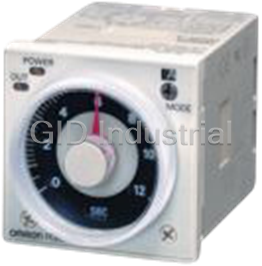
Omron H3CRA8AC100240 Solid-state Multifunctional Timer with Wide AC/DC Power Supply Range, DIN 48 x 48-mm
Part Number
H3CRA8AC100240
Price
Request Quote
Manufacturer
OMRON
Lead Time
Request Quote
Category
Timers
Features
- A wide AC/DC power supply range greatly reduces the number of timer models kept in stock.
- A wide range of applications with multiple operating modes, six modes for 11-pin models and four modes for 8-pin models.
- Easy sequence checking with instantaneous outputs for a zero set value.
- Ecological design with reduced current consumption.
- Length of 80 mm or less when panel-mounted with a P3GA-11 Socket (H3CR-A8E, 100 to 240 VAC, 100 to 125 VDC)
- PNP input models available.
- Standards: UL, CSA, NK, LR, EN 61812-1, and CE Marking.
Datasheet

Extracted Text
Solid-state Multi-functional Timers H3CR-A CSM_H3CR-A_DS_E_6_2 Multiple Operating Modes and Multiple Time Ranges. DIN 48 x 48-mm Multifunctional Timer with Wide AC/DC Power Supply Range for Both High and Low Voltages. • A wide AC/DC power supply range greatly reduces the number of timer models kept in stock. A wide range of applications with multiple operating modes, six modes for 11-pin models and four modes for 8-pin models. Ecological design with redu ced current consumption. Easy sequence checking with instantaneous outputs for a zero set value. LR Length of 80 mm or less when panel-mounted with a P3GA-11 Socket (H3CR-A8E, 100 to 240 VAC, 100 to 125 VDC) PNP input models available. Standards: UL, CSA, NK, LR, EN 61812-1, and CE Marking. Model Number Structure ■ Model Number Legend Note: This model number legend includes combinations that are not available. Before ordering, please check the List of Models on page 2 for avail- ability. H3CR-A@ @ @ - @ @ 12 3 4 5 1. Number of Pins None: 11-pin models 8: 8-pin models 2. Input Type for 11-pin Models None: No-voltage input (NPN type) P: Voltage input (PNP type) 3. Output None: Relay output (DPDT) S: Transistor output (NPN/PNP universal use) E: Relay output (SPDT) with instantaneous relay output (SPDT) 4. Suffix 300: Dual mode models (signal ON/OFF-delay and one-shot) 301: Double time scale (range) models (0.1 s to 600 h) 5. Supply Voltage 100-240AC/100-125DC: 100 to 240 VAC/100 to 125 VDC 24-48AC/12-48DC: 24 to 48 VAC/12 to 48 VDC 24-48AC/DC: 24 to 48 VAC/VDC (Only for H3CR-A8E) 1 H3CR-A Ordering Information ■ List of Models Note: 1. Specify both the model number and supply voltage when ordering. Example: H3CR-A 100-240AC/100-125DC Supply voltage 2. The operating modes are as follows A: ON-delay D: Signal OFF-delay B: Flicker OFF start E: Interval B2: Flicker ON start G: Signal ON/OFF-delay C: Signal ON/OFF-delay J: One-shot 11-pin Models Output Supply voltage Input type Time range Operating mode Model (See note 2) (See note 1.) Contact 100 to 240 VAC (50/60 Hz)/ No-voltage input 0.05 s to 300 h Six multi-modes: A, B, H3CR-A 100 to 125 VDC B2, C, D, E 24 to 48 VAC (50/60 Hz)/ 12 to 48 VDC 100 to 240 VAC (50/60 Hz)/ Dual-modes: G, J H3CR-A-300 100 to 125 VDC 24 to 48 VAC (50/60 Hz)/ 12 to 48 VDC 100 to 240 VAC (50/60 Hz)/ Voltage input Six multi-modes: A, B, H3CR-AP 100 to 125 VDC B2, C, D, E 24 to 48 VAC (50/60 Hz)/ 12 to 48 VDC 100 to 240 VAC (50/60 Hz)/ No-voltage input 0.1 s to 600 h H3CR-A-301 100 to 125 VDC 24 to 48 VAC (50/60 Hz)/ 12 to 48 VDC Transistor 24 to 48 VAC (50/60 Hz)/ 0.05 s to 300 h H3CR-AS (Photocoupler) 12 to 48 VDC 8-pin Models Output Supply voltage Input type Time range Operating mode Model (See note 2) (See note 1.) Contact 100 to 240 VAC (50/60 Hz)/ No-input available 0.05 s to 300 h Four multi-modes: A, H3CR-A8 100 to 125 VDC B2, E, J (Power supply start) 24 to 48 VAC (50/60 Hz)/ 12 to 48 VDC 100 to 240 VAC (50/60 Hz)/ 0.1 s to 600 h H3CR-A8-301 100 to 125 VDC 24 to 48 VAC (50/60 Hz)/ 12 to 48 VDC Transistor 24 to 48 VAC (50/60 Hz)/ 0.05 s to 300 h H3CR-A8S (Photocoupler) 12 to 48 VDC Time-limit contact and 100 to 240 VAC (50/60 Hz)/ H3CR-A8E instantaneous contact 100 to 125 VDC 24 to 48 VAC/VDC (50/60 Hz) 2 H3CR-A ■ Accessories (Order Separately) Adapter, Protective Cover, Hold down Clip, Setting Ring and Panel Cover Name/specifications Models Flush Mounting Adapter Y92F-30 Y92F-73 Y92F-74 Protective Cover Y92A-48B Hold-down Clip (Sold in sets of For PF085A Socket Y92H-8 two) For PL08 and PL11 Sockets Y92H-7 Setting Ring A Y92S-27 Setting Ring B and C Y92S-28 Panel Cover Light gray (5Y7/1) Y92P-48GL Black (N1.5) Y92P-48GB Medium gray (5Y5/1) Y92P-48GM Sockets Timer Round Sockets Pin Connection Terminal Models 11-pin Front Connecting DIN track mounting P2CF-11 DIN track mounting P2CF-11-E (Finger-safe type) Back Connecting Screw terminal P3GA-11 Solder terminal PL11 Wrapping terminal PL11-Q PCB terminal PLE11-0 8-pin Front Connecting DIN track mounting P2CF-08 DIN track mounting P2CF-08-E (Finger-safe type) DIN track mounting PF085A Back Connecting Screw terminal P3G-08 Solder terminal PL08 Wrapping terminal PL08-Q PCB terminal PLE08-0 Note: 1. The P2CF-@@-E has a finger-protection structure. Round crimp terminals cannot be used. Use forked crimp terminals. 2. The P3GA-11 and P3G-08 Socket can be used together with the Y92A-48G Terminal Cover to implement finger protection. 3. For details, refer to Socket and DIN Track Products. Terminal Cover Application Model Remarks For back connecting socket Y92A-48G For P3G-08 and P3GA-11 Note: For details, refer to Socket and DIN Track Products. 3 H3CR-A Specifications ■ General Item H3CR-A/-AS H3CR-AP H3CR-A8/-A8S H3CR-A8E Operating mode A: ON-delay A: ON-delay (power supply start) B: Flicker OFF start B2: Flicker ON start (power supply start) B2: Flicker ON start E: Interval (power supply start) C: Signal ON/OFF-delay J: One-shot (power supply start) D: Signal OFF-delay E: Interval G: Signal ON/OFF-delay (Only for H3CR-A-300) J: One-shot (Only for H3CR-A-300) Pin type 11-pin 8-pin Input type No-voltage input Voltage input --- Time-limit output type H3CR-A/-A8/-AP: Relay output (DPDT) Relay output (SPDT) H3CR-AS/-A8S: Transistor output (NPN/PNP universal)* Instantaneous output type --- Relay output (SPDT) Mounting method DIN track mounting, surface mounting, and flush mounting Approved standards UL508, CSA C22.2 No.14, NK, Lloyds Conforms to EN61812-1 and IEC60664-1 (VDE0110) 4kV/2. Output category according to EN60947-5-1 for Timers with Contact Outputs. Output category according to EN60947-5-2 for Timers with Transistor Outputs. *The internal circuits are optically isolated from the output. This enables universal application as NPN or PNP transistor. ■ Time Ranges Note: When the time setting knob is turned below “0” until the point where the time setting knob stops, the output will operate instantaneously at all time range settings. Standard (0.05-s to 300-h) Models Time unit s (sec) min (min) h (hrs) ×10 h (10 hrs) Full scale 1.2 0.05 to 1.2 0.12 to 1.2 1.2 to 12 setting 3 0.3 to 3 3 to 30 12 1.2 to 12 12 to 120 30 3 to 30 30 to 300 Double (0.1-s to 600-h) Models Time unit s (sec) min (min) h (hrs) ×10 h (10 hrs) Full scale 2.4 0.1 to 2.4 0.24 to 2.4 2.4 to 24 setting 6 0.6 to 6 6 to 60 24 2.4 to 24 24 to 240 60 6 to 60 60 to 600 4 H3CR-A ■ Ratings Rated supply voltage (See notes 1, 2, and 5.) 100 to 240 VAC (50/60 Hz)/100 to 125 VDC, 24 to 48 VAC (50/60 Hz)/12 to 48 VDC (24 to 48 VAC/VDC for H3CR- A8E) (See note3.) Operating voltage range 85% to 110% of rated supply voltage (90% to 110% at 12 VDC) Power reset Minimum power-opening time: 0.1 s Input No-voltage Input ON impedance: 1 kΩ max. ON residual voltage: 1 V max. OFF impedance: 100 kΩ min. Voltage Input Max. permissible capacitance between inputs lines (terminals 6 and 7): 1,200 pF Load connectable in parallel with inputs (terminals 6 and 7). • 100 to 240 VAC/100 to 125 VDC High (logic) level: 85 to 264 VAC/85 to 137.5 VDC Low (logic) level: 0 to 10 VAC/0 to 10 VDC • 24 to 48 VAC/12 to 48 VDC High (logic) level: 20.4 to 52.8 VAC/10.8 to 52.8 VDC Low (logic) level: 0 to 2.4 VAC/0 to 1.2 VDC Power consumption H3CR-A/-A8 • 100 to 240 VAC/100 to 125 VDC (When at 240 VAC, 60 Hz) Relay ON: approx. 2.0 VA (1.6 W) Relay OFF: approx. 1.3 VA (1.1 W) • 24 to 48 VAC/12 to 48 VDC (When at 24 VDC) Relay ON: approx. 0.8 W Relay OFF: approx. 0.2 W H3CR-AP (See note 3) • 100 to 240 VAC/100 to 125 VDC (When at 240 VAC, 60 Hz) Relay ON: approx. 2.5 VA (2.2 W) (See note 4.) Relay OFF: approx. 1.8 VA (1.7 W) (See note 4.) • 24 to 48 VAC/12 to 48 VDC (When at 24 VDC) Relay ON: approx. 0.9 W (See note 4.) Relay OFF: approx. 0.3 W (See note 4.) H3CR-A8E • 100 to 240 VAC/100 to 125 VDC (When at 240 VAC, 60 Hz) Relay ON/OFF: approx. 2 VA (0.9 W) • 24 to 48 VAC/VDC (When at 24 VDC) Relay ON/OFF: approx. 0.9 W H3CR-AS/-A8S • 24 to 48 VAC/12 to 48 VDC (When at 24 VDC) Output ON: 0.3 W Output OFF: 0.2 W Control outputs Time limit contacts: 5 A at 250 VAC/30 VDC, 0.15 A at 125 VDC, resistive load (cosφ = 1) Transistor output: Open collector (NPN/PNP), 100 mA max. at 30 VDC max., residual voltage: 2 V max. Instantaneous contact: 5 A at 250 VAC/30 VDC, 0.15 A at 125 VDC, resistive load (cosφ = 1) Note: 1. DC ripple rate: 20% max. (A single-phase, full-wave-rectification power supply can be used). 2. Do not use an inverter output as the power supply. Refer to Safety Precautions for All Timers for details. 3. Models with 24-to-48-VAC or 12-to-48-VDC power supply have inrush current. Caution is thus required when turning ON and OFF power to the Timer with a non-contact output from a device such as a sensor. (Models with an inrush current of approximately 50 mA and a 24- VDC power supply are available (the H3CR-A-302 and H3CR-A8-302).) 4. The values are for when the terminals 2 and 7 and terminals 10 and 6 are short-circuited, and include the consumption current of the input circuit. 5. Refer to Safety Precautions for All Timers when using the Timer together with a 2-wire AC proximity sensor. 5 H3CR-A ■ Characteristics Accuracy of operating ±0.2% FS max. (±0.2%±10 ms max. in a range of 1.2 s or 3 s) time Setting error ±5% FS ±50 ms (See note 1) Reset time Min. power-opening time: 0.1 s max. Min. pulse width: 0.05 s (H3CR-A/-AS) Reset voltage 10% max. of rated supply voltage Influence of voltage ±0.2% FS max. (±0.2%±10 ms max. in a range of 1.2 s or 3 s) Influence of temperature ±1% FS max. (±1%±10 ms max. in a range of 1.2 s or 3 s) Insulation resistance 100 MΩ min. (at 500 VDC) Dielectric strength 2,000 VAC (1,000 VAC for H3CR-A@S), 50/60 Hz for 1 min (between current-carrying metal parts and exposed non- current-carrying metal parts) 2,000 VAC (1,000 VAC for H3CR-A@S), 50/60 Hz for 1 min (between control output terminals and operating circuit) 2,000 VAC, 50/60 Hz for 1 min (between contacts of different polarities) 1,000 VAC, 50/60 Hz for 1 min (between contacts not located next to each other) 2,000 VAC, 50/60 Hz for 1 min (between input and control output terminals and operation circuit) for H3CR-AP Impulse withstand 3 kV (between power terminals) for 100 to 240 VAC/100 to 125 VDC, 1 kV for 24 to 48 VAC/12 to 48 VDC voltage 4.5 kV (between current-carrying terminal and exposed non-current-carrying metal parts) for 100 to 240 VAC/100 to 125 VDC, 1.5 kV for 24 to 48 VAC/12 to 48 VDC and 24 to 48 VAC/VDC Noise immunity ±1.5 kV (between power terminals) and ±600 V (between no-voltage input terminals), square-wave noise by noise simulator (pulse width: 100 ns/1 μs, 1-ns rise) Static immunity Malfunction: 8 kV Destruction: 15 kV Vibration resistance Destruction: 10 to 55 Hz with 0.75-mm single amplitude each in 3 directions for 2 hours each Malfunction: 10 to 55 Hz with 0.5-mm single amplitude each in 3 directions for 10 minutes each 2 Shock resistance Destruction: 1,000 m/s 3 times each in 6 directions 2 Malfunction: 100 m/s 3 times each in 6 directions Ambient temperature Operating: −10°C to 55°C (with no icing) Storage: −25°C to 65°C (with no icing) Ambient humidity Operating: 35% to 85% Life expectancy Mechanical: 20,000,000 operations min. (under no load at 1,800 operations/h) Electrical: 100,000 operations min. (5 A at 250 VAC, resistive load at 1,800 operations/h) (See note 2) EMC (EMI) EN61812-1 Emission Enclosure: EN55011 Group 1 class A Emission AC Mains: EN55011 Group 1 class A (EMS) EN61812-1 Immunity ESD: IEC61000-4-2: 6 kV contact discharge (level 3) 8 kV air discharge (level 3) Immunity RF-interference from AM Radio Waves: IEC61000-4-3: 10 V/m (80 MHz to 1 GHz) (level 3) Immunity RF-interference from Pulse-modulated Radio Waves:IEC61000-4-3: 10 V/m (900±5 MHz) (level 3) Immunity Conducted Disturbance: IEC61000-4-6: 10 V (0.15 to 80 MHz) (level 3) Immunity Burst: IEC61000-4-4: 2 kV power-line (level 3) 2 kV I/O signal-line (level 4) Immunity Surge: IEC61000-4-5: 1 kV line to line (level 3) 2 kV line to ground (level 3) Case color Light gray (Munsell 5Y7/1) Degree of protection IP40 (panel surface) Weight Approx. 90 g Note: 1. The value is ±5% FS +100 ms to −0 ms max. when the C, D, or G mode signal of the H3CR-AP is OFF. 2. Refer to the Life-test Curve. 3. Relay output only. ■ Life-test Curve 10,000 5,000 1,000 Reference: A maximum current of 0.15 A can be switched at 125 VDC (cosφ = 1) 30 VDC L/R = 7 ms 500 and a maximum current of 0.1 A can be switched if L/R is 7 ms. In 250 VAC/30 VDC both cases, a life of 100,000 operations can be expected. (cosφ = 1) The minimum applicable load is 10 mA at 5 VDC (failure level: P). 100 250 VAC (cosφ = 0.4) Load current (A) 6 3 Switching operations (x 10 ) H3CR-A Connections ■ Block Diagrams H3CR-A/AS Zero setting AC (DC) input Time range/ Operating detection unit selectors mode selector circuit Power supply Oscillation Counting Output circuit circuit circuit circuit Indicator Reset input, start input, and gate input Input circuit circuit Power-ON Output-ON indicator indicator H3CR-AP Zero setting Time range/ Operating AC (DC) input detection unit selectors mode selector circuit Power supply Oscillation Counting Output circuit circuit circuit circuit Indicator Start Input circuit circuit Power-ON Output-ON indicator indicator 7 H3CR-A H3CR-A8/A8S Zero setting AC (DC) input Time range/ Operating detection unit selectors mode selector circuit Power supply Oscillation Counting Output circuit circuit circuit circuit Indicator circuit Power-ON Output-ON indicator indicator H3CR-A8E Zero setting Time range/ Operating AC (DC) input detection unit selectors mode selector circuit Power supply Oscillation Counting Output circuit circuit circuit circuit Indicator circuit Power-ON Output-ON indicator indicator Instantaneous output circuit ■ I/O Functions Inputs (for -A/ Start Starts time-measurement. -AS models) Reset Interrupts time-measurement and resets time-measurement value. No time-measurement is made and control output is OFF while the reset input is ON. Gate Prohibits time-measurement. Outputs Control output Outputs are turned ON according to designated output mode when preset value is reached. Note: H3CR-AP incorporates start input only. 8 H3CR-A ■ Terminal Arrangement Note: The delayed contact of conventional Timers was indicated as The contact symbol of the H3CR-A is indicated as because its operating mode is six multi-modes (four multi-modes for the H3CR-A8). 11-pin Models 8-pin Models H3CR-A/-A-300/-A-301 (Contact Output) H3CR-A8/-A8-301 (Contact Output) Power supply H3CR-A8S (Transistor Output) Power supply H3CR-AS (Transistor Output) Power supply Note: Terminals 1, 3, 4, and 5 are empty. Terminals 2 and 7 are the same as for the H3CR-A8. H3CR-A8E (Contact Output) Power supply Note: Terminals 1, 3, 4, and 8 are empty. Terminals 2, 5, 6, 7, and 10 are the same as for the H3CR-A. H3CR-AP (Contact Output) Power supply Power supply Note: 1. Terminal 5 is empty. 2. Separate power supplies can be used for the Timer and in- puts. 9 Reset input Reset input Start input Start input Start input Gate input Gate input H3CR-A ■ Input Connections H3CR-A/-AS The inputs of the H3CR-A/-AS are no-voltage (short-circuit or open) inputs. No-voltage Inputs No-contact Input Contact Input No-contact Input (Connection to NPN open (Connection to a voltage collector output sensor.) output sensor.) 12 to 24 VDC 12 to 24 VDC (sensor power supply) (sensor power supply) + + DC power DC power − − supply supply Timer Timer Timer Sensor Sensor 5 Gate 5 Gate 5 Gate 6 Start 6 Start 6 Start 7 Reset 7 Reset 7 Reset 2 Input (0 V) 2 Input (0 V) 2 Input (0 V) Operates with relay ON Operates with transistor ON Operates with transistor ON No-voltage Input Signal Levels No-contact 1. Short-circuit level input Transistor ON Residual voltage: 1 V max. Impedance when ON: 1 kΩ max. 2. Open level Transistor OFF Impedance when OFF: 100 kΩ min. Contact Use contacts which can input adequately switch 0.1 mA at 5 V 10 H3CR-A H3CR-AP The start input of the H3CR-AP is voltage input. (Voltage imposition or open) Voltage Inputs No-contact Input No-contact Input Contact Input (Connection to PNP open (Connection to NPN open collector output sensor) collector output sensor) 12 to 24 VDC 12 to 24 VDC (sensor power supply) (sensor power supply) + DC power + DC power supply supply − − Sensor Sensor Timer Timer Timer Power Power 10 10 Power 10 supply (+) supply (+) supply (+) 6 Start 6 Start Start 6 7 Input 0V 7 Input 0V Input 0V 7 Power Power 2 2 Power supply (−) 2 supply (−) supply (−) Operates with relay ON Operates with PNP transistor ON Operates with NPN transistor ON Note: The input circuit is isolated from the Note: Refer to the signal levels in the power supply circuit. Thus, an NPN following table and be aware of the transistor can be connected. minimum applicable load of the relay. Note: Before making connections, refer to Safety Precautions (H3CR-@). Voltage Input Signal Levels No-contact 1. Transistor ON input Residual voltage: 1 V max. The voltage between terminals 6 and 7 must be 10.8 VDC min. 2. Transistor OFF Leakage current: 0.01 mA max. The voltage between terminals 6 and 7 must be 1.2 VDC max. Contact Use contacts that can adequately switch 0.1 mA at each input operating voltage. The voltage between terminals 6 and 7 with contacts ON or OFF must satisfy the specified value. Contacts ON 100-to-240-VAC and 100-to-125-VDC models: 85 to 264 VAC or 85 to 137.5 VDC 24-to-48-VAC and 12-to-48-VDC models: 20.4 to 52.8 VAC or 10.8 to 52.8 VDC Contacts OFF 100-to-240-VAC and 100-to-125-VDC models: 0 to 10 VAC or 0 to 10 VDC 24-to-48-VAC and 12-to-48-VDC models: 0 to 2.4 VAC or 0 to 1.2 VDC 11 AC power supply DC power supply H3CR-A Operation ■ Timing Chart Note: 1. The minimum power-opening time (“Rt”) is 0.1 s. 2. The minimum input pulse width (for start, reset) is 0.05 s. 3. The letter “t” in the timing charts stands for the set time and “t–a” means that the period is less than the time set. 4. Power supply start in mode J is also possible for H3CR-A8/-A8E/-A8S/-A8-301 models. 5. Refer to page 17 for application examples. H3CR-A/-AS/-AP* *H3CR-AP model incorporates start input only. Operating Timing chart mode A: ON-delay t t Basic operation Power Power Start Start Reset (See note) t Output relay (NC) Output Output relay (NO) (Output indicator) Note: Start input is invalid while the Timer is in operation. Power indicator B: Basic operation Flicker OFF Power start Power Start Reset Start (See note) t t t t Output relay (NC) Output Output relay (NO) (Output indicator) Note: Start input is invalid while Power indicator the Timer is in operation. B2: Basic operation Flicker ON start Power Power Start Reset Start (See note) t t t t Output relay (NC) Output Output relay (NO) (Output indicator) Note: Start input is invalid while the Timer is in operation. Power indicator C: Basic operation Signal ON/ OFF-delay Power Power Start Start Reset tt t t (See note) Output relay (NC) Output Output relay (NO) Note: Start input is valid and (Output indicator) retriggerable while the Timer Power indicator is in operation. 12 H3CR-A Operating Timing chart mode D: Basic operation Signal OFF- Power delay Power Start Reset Start (See note) t Output relay (NC) Output Output relay (NO) (Output indicator) Note: Start input is valid and Power indicator retriggerable while the Timer is in operation. E: Basic operation Interval Power Power Start Start t Reset (See note) Output relay (NC) Output Output relay (NO) Note: Start input is valid and (Output indicator) retriggerable while the Power indicator Timer is in operation. G: Basic operation Signal ON/ Power OFF-delay Power Start Start Reset (See note) t t t t Output relay (NC) Output Output relay (NO) (Output indicator) Note: Start input is valid and retriggerable while the Timer Power indicator is in operation. J: Basic operation One-shot Power output Power Start Reset Start (See note) t 1±0.6 s Output relay (NC) (Fixed) 1±0.6 s 1±0.6 s Output (Fixed) (Fixed) Output relay (NO) (Output indicator) Note: Start input is valid and Power indicator retriggerable while the Timer is in operation. (Previous start input will be cancelled.) Gate Signal Input t1 t2 ON Power OFF Start ON OFF ON Gate OFF ON Reset OFF Output ON relay OFF Note: 1. This timing chart indicates the gate input in operating mode A (ON-delay operation). 2. The set time is the sum of t1 and t2. 3. H3CR-AP model incorporates start input only. 13 H3CR-A H3CR-A8/-A8S Operating Timing chart mode A: ON-delay Power Basic operation Output relay (NC) Power t Output relay (NO) (output Output indicator) Power indicator B2: Flicker ON Power start Basic operation Output relay (NC) Power Output relay t t t t (NO) (output indicator) Output Power indicator v E: Interval Power Basic operation Output relay (NC) Power Output relay t (NO) (output indicator) Output Power indicator J: One-shot output Power Basic operation Output relay (NC) 1±0.6 s 1±0.6 s Power Output relay (Fixed) (Fixed) (NO) (output t 1±0.6 s indicator) (Fixed) Output Power indicator Note: 1. The minimum power-opening time (“Rt”) is 0.1 s. 2. The letter “t” in the timing charts stands for the set time and “t–a” means that the period is less than the time set. 14 H3CR-A H3CR-A8E Operating Timing chart mode A: ON-delay Power Output relay (NC) Output relay (NO) Basic operation (output indicator) Instantaneous Power output relay (NC) t Instantaneous output relay (NO) Output Power indicator B2: Flicker ON start Power Output relay (NC) Basic operation Output relay (NO) (output indicator) Power Instantaneous t tt t output relay (NC) Output Instantaneous output relay (NO) Power indicator E: Interval Power Output relay (NC) Output relay (NO) (output indicator) Basic operation Instantaneous output relay (NC) Power Instantaneous t output relay (NO) Output Power indicator J: One-shot Power output Output relay (NC) Output relay (NO) (Fixed) (Fixed) Basic operation (output indicator) Instantaneous Power output relay (NC) t Instantaneous 1±0.6 s output relay (NO) (Fixed) Output Power indicator Note: 1. The minimum power-opening time (“Rt”) is 0.1 s. 2. The letter “t” in the timing charts stands for the set time and “t–a” means that the period is less than the time set. Nomenclature Power indicator (green) (Flashes when Timer operates; lit when Timer stops operating) Operating mode display window Operating mode selector Select a mode from: Output indicator (orange) A, B, B2, C, D, and E (H3CR-A, -AP, and -AS) A, (Lit when output) B2, E and J (H3CR-A8, -A8S, and -A8E) G and J (H3CR-A-300) Scale range display windows Time unit display window Time range selector (select one from 1.2, 3, 12, and 30 at full scale; with the H3CR-A@-301, Time unit selector (select one select from 2.4, 6, 24, or 60 at Time setting from sec, min, hrs, and 10h) full scale.) knob (set time) 15 H3CR-A Dimensions Note: All units are in millimeters unless otherwise indicated. H3CR-A 15 H3CR-AP 66.6 6 52.3 H3CR-AS 48 0.7 48 39 dia. 44.8 × 44.8 11 pins H3CR-A8 H3CR-A8S 15 66.6 H3CR-A8E 6 52.3 48 0.7 39 dia. 48 44.8 × 44.8 8 pins Dimensions with Set Ring 16.5 50 42 dia. 50 Panel cover Time Setting Ring Dimensions with Front Connecting Socket Dimensions with Back Connecting Socket P2CF-08-@/P2CF-11-@ P3G-08/P3GA-11 81.5 81.5 15 15 80 75 H3CR-A8@ H3CR-A H3CR-AS H3CR-A H3CR-A8@ 98.5 89.9* 87.6 100.8* H3CR-AP H3CR-AS + Adapter H3CR-AP + Adapter P3G-08 P3GA-11 Y92F-30 Y92F-30 (When (When Y92A-48G 2.3* P2CF-11 2.3* P2CF-08 Y92A-48G mounted) P2CF-11-E P2CF-08-E mounted) *These dimensions vary with the kind of DIN track (reference value). 16 H3CR-A Application Examples (H3CR-A) A Mode: ON-delay ON-delay operation (A mode) is a basic mode. 1. Power-ON Start/Power-OFF Reset 3. Control of Integrated Time with Gate Signal The Power-ON start/Power-OFF reset operation is a standard operating method. With a gate signal, the Power-ON start operation and Signal start operation can be controlled (the operation can be interrupted). tt Power (2 and 10) t1 t1 + t2: set time t2 Start (2 and 6) Power (2 and 10) Reset (2 and 7) Start (2 and 6) Control output: NC (8 and 11) Gate (2 and 5) NC (1 and 4) Control output: NO (9 and 11) Control output: NC (8 and 11) NO (1 and 3) NC (1 and 4) Power indicator Control output: NO (9 and 11) NO (1 and 3) Flashing Lit Power indicator Externally short-circuited Flashing Lit Gate signal (The operation is interrupted with the gate signal if the Timer detects an abnormal signal.) Externally short-circuited Power supply Power 2. Signal Start/Signal Reset supply The Signal start/Signal reset operation is useful for remote control of the Timer. B/B2 Mode: Flicker The flicker operation in the B and B2 modes can be effectively Power (2 and 10) applied to lamp or buzzer (ON and OFF) alarms or the monitoring of an intermittent operation with a display. Start (2 and 6) 1. Power-ON Start/Power-OFF Reset (in B Reset (2 and 7) Mode) Control output: NC (8 and 11) NC (1 and 4) Control output: NO (9 and 11) Power (2 and 10) NO (1 and 3) Power indicator Start (2 and 6) Lit Flashing Lit Control output: NC (8 and 11) NC (1 and 4) Control output: NO (9 and 11) Start signal (remote control possible) NO (1 and 3) Reset signal (remote control possible) Power indicator Flashing Externally short-circuited Power supply (Power continuously supplied) Power supply 17 H3CR-A 2. Signal Start/Signal Reset (in B Mode) 2. Signal-ON-OFF Start/Instantaneous Operation/Time-limit Reset If there is an abnormal signal, flashing starts. When the abnormal condition is restored, a reset signal stops the display flashing. tt Power (2 and 10) Power (2 and 10) Start (2 and 6) Start (2 and 6) Control output: NC (8 and 11) NC (1 and 4) Control output: NO (9 and 11) Reset (2 and 7) NO (1 and 3) Control output: NC (8 and 11) NC (1 and 4) Power indicator Control output: NO (9 and 11) NO (1 and 3) Power indicator Lit Flashing Lit Start signal (The operation starts with the signal ON or OFF) Start signal Reset signal Power supply Power (Power continuously supplied) supply (Power continuously supplied) D Mode: Signal OFF-delay C Mode: Signal ON/OFF-delay Signal OFF-delay operation (D mode) can be effectively used to keep a load operating for a certain period. For example, this function The Signal ON-/OFF-delay operation (C mode) is useful for the enables the cooling fan for a lamp or heater to operate for a certain control of distribution of products on a production line into boxes by period after the lamp or heater is switched OFF. the specified number or time. 1. Power-ON Start/Instantaneous Operation/ 1. Power-ON Start/Instantaneous Operation/ Time-limit Reset Time-limit Reset A set of these functions is useful for the operation of a machine for a specified period when power is ON. Power (2 and 10) Start (2 and 6) tt Control output: NC (8 and 11) Power (2 and 10) NC (1 and 4) Control output: NO (9 and 11) Start (2 and 6) NO (1 and 3) Control output: NC (8 and 11) Power indicator NC (1 and 4) Lit Flashing Lit Control output: NO (9 and 11) NO (1 and 3) Power indicator Start signal (NC to NO) Flashing Lit Flashing Lit Externally short-circuited Power supply Power supply 18 Lit Flashing Lit Flashing Lit Flashing Lit H3CR-A 2. Signal Start/Instantaneous Operation/ 2. Signal Start/Instantaneous Operation/ Time-limit Reset Time-limit Reset This function is useful for the repetitive control such as the filling of liquid for a specified period after each Signal start input. Power (2 and 10) Start (2 and 6) t t Power (2 and 10) Control output: NC (8 and 11) NC (1 and 4) Start (2 and 6) Control output: NO (9 and 11) NO (1 and 3) Control output: NC (8 and 11) Power indicator NC (1 and 4) Lit Flashing Lit Control output: NO (9 and 11) NO (1 and 3) Power indicator Start signal (NO to NC to NO) Flashing Lit Flashing Lit Start signal Power supply Power (Power continuously supplied) supply (Power continuously supplied) E Mode: Interval 1. Power-ON Start/Instantaneous Operation/ Time-limit Reset This function is useful for the operation of a machine for a specified period after power is ON. tt Power (2 and 10) Start (2 and 6) Control output: NC (8 and 11) NC (1 and 4) Control output: NO (9 and 11) NO (1 and 3) Power indicator Flashing Lit Flashing Lit Externally short-circuited Power supply 19 H3CR-A Safety Precautions (H3CR-A) Refer to Safety Precautions for All Timers. Note: The following precautions apply to all H3CR-A models. ■ Power Supplies ■ Input/Output For the power supply of an input device of the H3CR-A@/-A@S/-AP, use an isolating transformer with the primary and secondary Relationship between Input and Power windings mutually isolated and the secondary winding not grounded. Supply Circuits (except for H3CR-A8E) Correct The H3CR-A (except for H3CR-A8E) uses transformerless power supply. When connecting a relay or transistor as an external signal H3CR-A input device, pay attention to the following points to prevent short- G, S, R circuiting due to a sneak current to the transformerless power supply. 5, 6, 7 10 If a relay or transistor is connected to two or more Timers, the input Input terminal Power supply terminals of those Timers must be wired properly so that they will not 2 2 differ in phase, otherwise the terminals will be short-circuited to one another. Short-circuit current Incorrect H3CR-A Contact or transistor for external input signal Input Isolation transformer is required. Power supply terminal Input device Incorrect H3CR-A G, S, R 10 5, 6, 7 Input Input terminal Power terminal 2 2 supply Correct Input Power supply terminal Input device Isolation transformer The H3CR-A@/-A@S/AP’s power supply terminal 2 is a common ter- minal for input signals to the Timer. Do not disconnect the wires on terminal 2, otherwise the internal circuitry of the Timer will be dam- Input terminal aged. 10 It is impossible to provide two independent power switches as shown 5, 6, 7 below regardless of whether or not the Timers are different in phase. G, S, R Input terminal H3CR-A Input Power supply terminal 2 Make sure that the voltage is applied within the specified range, oth- erwise the internal elements of the Timer may be damaged. Input terminal 20 H3CR-A If a relay or transistor is connected to two or more Timers, the input Relationship between Input and Power terminals of those Timers must be wired properly so that they will not be different in phase or the terminals will be short-circuited to one Supply Circuits (H3CR-A@/-A@S) another (refer to the figures below). An appropriate input is applied to the input signal terminals of the H3CR-A@/-A@S when one of the input terminals is short-circuited Incorrect Contact or transistor for external input signal with the common terminal (terminal 2) for the input signals. Never use terminal 10 as the common terminal for this purpose, otherwise 10 the internal circuit of the Timer will be damaged. 6 Incorrect H3CR-AP Power supply 7 10 2 H3CR-A AC or DC 5, 6, 7 power supply G, S, R 10 Input terminal 6 2 Short-circuit current H3CR-AP 7 Correct 2 10 5, 6, 7 Correct Contact or transistor for G, S, R external input signal Input terminal H3CR-A 10 AC or DC power supply 6 2 Power supply H3CR-AP 7 2 Do not connect a relay or any other load between input terminals, otherwise the internal circuit of the Timer will be damaged due to the Short-circuit current high-tension voltage applied to the input terminals. 10 6 10 H3CR-AP Ry 7 H3CR-A AC or DC 5, 6, 7 2 power supply G, S, R Input terminal 2 Input Common to All H3CR-A Models contact With the H3CR-AP, input wires must be as short as possible. If the floating capacity of wires exceeds 1,200 pF (approx. 10 m for cables with 120 pF/m), the operation will be affected. Pay particular Relationship between Input and Power attention when using shielded cables. Supply Circuits (H3CR-AP) The H3CR-A@S transistor output is isolated from the internal circuitry by a photocoupler. Therefore, either NPN or PNP output is possible. H3CR-AP AC/DC power Power supply supply Input circuit circuit Since the input circuit and the power supply circuit are configured independently, the input circuit can be turned ON or OFF irrespective of the ON/OFF state of the power supply. It must be noted that a voltage equivalent to the power supply voltage is applied to the input circuit. ALL DIMENSIONS SHOWN ARE IN MILLIMETERS. To convert millimeters into inches, multiply by 0.03937. To convert grams into ounces, multiply by 0.03527. In the interest of product improvement, specifications are subject to change without notice. 21 Read and Understand This Catalog Please read and understand this catalog before purchasing the products. Please consult your OMRON representative if you have any questions or comments. Warranty and Limitations of Liability WARRANTY OMRON's exclusive warranty is that the products are free from defects in materials and workmanship for a period of one year (or other period if specified) from date of sale by OMRON. OMRON MAKES NO WARRANTY OR REPRESENTATION, EXPRESS OR IMPLIED, REGARDING NON-INFRINGEMENT, MERCHANTABILITY, OR FITNESS FOR PARTICULAR PURPOSE OF THE PRODUCTS. ANY BUYER OR USER ACKNOWLEDGES THAT THE BUYER OR USER ALONE HAS DETERMINED THAT THE PRODUCTS WILL SUITABLY MEET THE REQUIREMENTS OF THEIR INTENDED USE. OMRON DISCLAIMS ALL OTHER WARRANTIES, EXPRESS OR IMPLIED. LIMITATIONS OF LIABILITY OMRON SHALL NOT BE RESPONSIBLE FOR SPECIAL, INDIRECT, OR CONSEQUENTIAL DAMAGES, LOSS OF PROFITS OR COMMERCIAL LOSS IN ANY WAY CONNECTED WITH THE PRODUCTS, WHETHER SUCH CLAIM IS BASED ON CONTRACT, WARRANTY, NEGLIGENCE, OR STRICT LIABILITY. In no event shall the responsibility of OMRON for any act exceed the individual price of the product on which liability is asserted. IN NO EVENT SHALL OMRON BE RESPONSIBLE FOR WARRANTY, REPAIR, OR OTHER CLAIMS REGARDING THE PRODUCTS UNLESS OMRON'S ANALYSIS CONFIRMS THAT THE PRODUCTS WERE PROPERLY HANDLED, STORED, INSTALLED, AND MAINTAINED AND NOT SUBJECT TO CONTAMINATION, ABUSE, MISUSE, OR INAPPROPRIATE MODIFICATION OR REPAIR. Application Considerations SUITABILITY FOR USE OMRON shall not be responsible for conformity with any standards, codes, or regulations that apply to the combination of products in the customer's application or use of the products. At the customer's request, OMRON will provide applicable third party certification documents identifying ratings and limitations of use that apply to the products. This information by itself is not sufficient for a complete determination of the suitability of the products in combination with the end product, machine, system, or other application or use. The following are some examples of applications for which particular attention must be given. This is not intended to be an exhaustive list of all possible uses of the products, nor is it intended to imply that the uses listed may be suitable for the products: · Outdoor use, uses involving potential chemical contamination or electrical interference, or conditions or uses not described in this catalog. · Nuclear energy control systems, combustion systems, railroad systems, aviation systems, medical equipment, amusement machines, vehicles, safety equipment, and installations subject to separate industry or government regulations. · Systems, machines, and equipment that could present a risk to life or property. Please know and observe all prohibitions of use applicable to the products. NEVER USE THE PRODUCTS FOR AN APPLICATION INVOLVING SERIOUS RISK TO LIFE OR PROPERTY WITHOUT ENSURING THAT THE SYSTEM AS A WHOLE HAS BEEN DESIGNED TO ADDRESS THE RISKS, AND THAT THE OMRON PRODUCTS ARE PROPERLY RATED AND INSTALLED FOR THE INTENDED USE WITHIN THE OVERALL EQUIPMENT OR SYSTEM. PROGRAMMABLE PRODUCTS OMRON shall not be responsible for the user's programming of a programmable product, or any consequence thereof. Disclaimers CHANGE IN SPECIFICATIONS Product specifications and accessories may be changed at any time based on improvements and other reasons. It is our practice to change model numbers when published ratings or features are changed, or when significant construction changes are made. However, some specifications of the products may be changed without any notice. When in doubt, special model numbers may be assigned to fix or establish key specifications for your application on your request. Please consult with your OMRON representative at any time to confirm actual specifications of purchased products. DIMENSIONS AND WEIGHTS Dimensions and weights are nominal and are not to be used for manufacturing purposes, even when tolerances are shown. PERFORMANCE DATA Performance data given in this catalog is provided as a guide for the user in determining suitability and does not constitute a warranty. It may represent the result of OMRON’s test conditions, and the users must correlate it to actual application requirements. Actual performance is subject to the OMRON Warranty and Limitations of Liability. ERRORS AND OMISSIONS The information in this document has been carefully checked and is believed to be accurate; however, no responsibility is assumed for clerical, typographical, or proofreading errors, or omissions. 2010.12 In the interest of product improvement, specifications are subject to change without notice. OMRON Corporation Industrial Automation Company http://www.ia.omron.com/ (c)Copyright OMRON Corporation 2010 All Right Reserved.
Frequently asked questions
How does Industrial Trading differ from its competitors?

Is there a warranty for the H3CRA8AC100240?
Which carrier will Industrial Trading use to ship my parts?
Can I buy parts from Industrial Trading if I am outside the USA?
Which payment methods does Industrial Trading accept?


What they say about us
FANTASTIC RESOURCE
One of our top priorities is maintaining our business with precision, and we are constantly looking for affiliates that can help us achieve our goal. With the aid of GID Industrial, our obsolete product management has never been more efficient. They have been a great resource to our company, and have quickly become a go-to supplier on our list!
Bucher Emhart Glass
EXCELLENT SERVICE
With our strict fundamentals and high expectations, we were surprised when we came across GID Industrial and their competitive pricing. When we approached them with our issue, they were incredibly confident in being able to provide us with a seamless solution at the best price for us. GID Industrial quickly understood our needs and provided us with excellent service, as well as fully tested product to ensure what we received would be the right fit for our company.
Fuji
HARD TO FIND A BETTER PROVIDER
Our company provides services to aid in the manufacture of technological products, such as semiconductors and flat panel displays, and often searching for distributors of obsolete product we require can waste time and money. Finding GID Industrial proved to be a great asset to our company, with cost effective solutions and superior knowledge on all of their materials, it’d be hard to find a better provider of obsolete or hard to find products.
Applied Materials
CONSISTENTLY DELIVERS QUALITY SOLUTIONS
Over the years, the equipment used in our company becomes discontinued, but they’re still of great use to us and our customers. Once these products are no longer available through the manufacturer, finding a reliable, quick supplier is a necessity, and luckily for us, GID Industrial has provided the most trustworthy, quality solutions to our obsolete component needs.
Nidec Vamco
TERRIFIC RESOURCE
This company has been a terrific help to us (I work for Trican Well Service) in sourcing the Micron Ram Memory we needed for our Siemens computers. Great service! And great pricing! I know when the product is shipping and when it will arrive, all the way through the ordering process.
Trican Well Service
GO TO SOURCE
When I can't find an obsolete part, I first call GID and they'll come up with my parts every time. Great customer service and follow up as well. Scott emails me from time to time to touch base and see if we're having trouble finding something.....which is often with our 25 yr old equipment.
ConAgra Foods