

 Manufacturers
MOTOROLA MPC5200CVR400B

Description
760 MIPS at 400 MHz Single Board Computer, 16 k Instruction cache, 16 k Data cache, up to 133-MHz operation, (-40 to +85 oC)
Part Number
MPC5200CVR400B
Price
Request Quote
Manufacturer
MOTOROLA
Lead Time
Request Quote
Category
None
Datasheet


Extracted Text
MPC5200BDS Freescale Semiconductor Rev. 0.7, 10/2005 Data Sheet: Technical Data MPC5200B Data Sheet Table of Contents NOTE 1 Overview. . . . . . . . . . . . . . . . . . . . . . . . . . . . . . . . . . . . . 1 The information in this 2 Features. . . . . . . . . . . . . . . . . . . . . . . . . . . . . . . . . . . . . . 2 document is subject to 3 Electrical and Thermal Characteristics. . . . . . . . . . . . . . 6 change. For the latest data 3.1 DC Electrical Characteristics . . . . . . . . . . . . . . . . . 6 on the MPC5200B, visit 3.2 Oscillator and PLL Electrical Characteristics. . . . 12 3.3 AC Electrical Characteristics . . . . . . . . . . . . . . . . 14 www.mobilegt.com and 4 Package Description . . . . . . . . . . . . . . . . . . . . . . . . . . . 61 proceed to the 4.1 Package Parameters . . . . . . . . . . . . . . . . . . . . . . . 61 MPC5200B Product 4.2 Mechanical Dimensions . . . . . . . . . . . . . . . . . . . . 61 4.3 Pinout Listings . . . . . . . . . . . . . . . . . . . . . . . . . . . 63 Summary Page. 5 System Design Information . . . . . . . . . . . . . . . . . . . . . 68 5.1 Power Up/Down Sequencing . . . . . . . . . . . . . . . . 68 5.2 System and CPU Core AVDD Power Supply Filter- 1Overview ing70 5.3 Pull-up/Pull-down Resistor Requirements . . . . . . 70 The MPC5200B integrates a high performance 5.4 JTAG . . . . . . . . . . . . . . . . . . . . . . . . . . . . . . . . . . 71 MPC603e series e300 core with a rich set of peripheral 6 Ordering Information . . . . . . . . . . . . . . . . . . . . . . . . . . 75 7 Document Revision History . . . . . . . . . . . . . . . . . 76 functions focused on communications and systems integration. The e300 core design is based on the ® PowerPC core architecture. MPC5200B incorporates an innovative BestComm I/O subsystem, which isolates routine maintenance of peripheral functions from the embedded e300 core. The MPC5200B contains a SDRAM/DDR Memory Controller, a flexible External Bus Interface, PCI Controller, USB, ATA, Ethernet, six © Freescale Semiconductor, Inc., 2005. All rights reserved. Features 2 Programmable Serial Controllers (PSC), I C, SPI, CAN, J1850, Timers, and GPIOs. 2Features Key features are shown below. • MPC603e series e300 core — Superscalar architecture o — 760 MIPS at 400 MHz (-40 to +85 C) — 16 k Instruction cache, 16 k Data cache — Double precision FPU — Instruction and Data MMU — Standard and Critical interrupt capability • SDRAM / DDR Memory Interface — up to 133-MHz operation — SDRAM and DDR SDRAM support — 256-MByte addressing range per CS, two CS available — 32-bit data bus — Built-in initialization and refresh • Flexible multi-function External Bus Interface — Supports interfacing to ROM/Flash/SRAM memories or other memory mapped devices — 8 programmable Chip Selects — Non multiplexed data access using 8/16/32 bit databus with up to 26-bit address — Short or Long Burst capable — Multiplexed data access using 8/16/32 bit databus with up to 25-bit address • Peripheral Component Interconnect (PCI) Controller — Version 2.2 PCI compatibility — PCI initiator and target operation — 32-bit PCI Address/Data bus — 33- and 66-MHz operation — PCI arbitration function • ATA Controller — Version 4 ATA compatible external interface—IDE Disk Drive connectivity • BestComm DMA subsystem — Intelligent virtual DMA Controller — Dedicated DMA channels to control peripheral reception and transmission — Local memory (SRAM 16 kBytes) MPC5200B Data Sheet, Rev. 0.7 2 Freescale Semiconductor Features • 6 Programmable Serial Controllers (PSC), configurable for the following: — UART or RS232 interface 2 — CODEC interface for Soft Modem, Master/Slave CODEC Mode, I S and AC97 — Full duplex SPI mode — IrDA mode from 2400 bps to 4 Mbps • Fast Ethernet Controller (FEC) — Supports 100Mbps IEEE 802.3 MII, 10 Mbps IEEE 802.3 MII, 10 Mbps 7-wire interface • Universal Serial Bus Controller (USB) — USB Revision 1.1 Host — Open Host Controller Interface (OHCI) — Integrated USB Hub, with two ports. 2 • Two Inter-Integrated Circuit Interfaces (I C) • Serial Peripheral Interface (SPI) • Dual CAN 2.0 A/B Controller (MSCAN) — Motorola Scalable Controller Area Network (MSCAN) architecture — Implementation of version 2.0A/B CAN protocol — Standard and extended data frames • J1850 Byte Data Link Controller (BDLC) — J1850 Class B data communication network interface compatible and ISO compatible for low speed (<125 kbps) serial data communications in automotive applications. — Supports 4X mode, 41.6 kbps — In-frame response (IFR) types 0, 1, 2, and 3 supported • Systems level features — Interrupt Controller supports four external interrupt request lines and 47 internal interrupt sources — GPIO/Timer functions – Up to 56 total GPIO pins (depending on functional multiplexing selections) that support a variety of interrupt/WakeUp capabilities. – Eight GPIO pins with timer capability supporting input capture, output compare, and pulse width modulation (PWM) functions — Real-time Clock with one-second resolution — Systems Protection (watch dog timer, bus monitor) — Individual control of functional block clock sources — Power management: Nap, Doze, Sleep, Deep Sleep modes — Support of WakeUp from low power modes by different sources (GPIO, RTC, CAN) MPC5200B Data Sheet, Rev. 0.7 Freescale Semiconductor 3 Features • Test/Debug features — JTAG (IEEE 1149.1 test access port) — Common On-chip Processor (COP) debug port • On-board PLL and clock generation Figure 1 shows a simplified MPC5200B block diagram. MPC5200B Data Sheet, Rev. 0.7 4 Freescale Semiconductor Features MSCAN 2x J1850 USB 2x SPI 2 I C 2x BestComm DMA Ethernet PSC SRAM 16K 6x Figure 1. Simplified Block Diagram—MPC5200B MPC5200B Data Sheet, Rev. 0.7 Freescale Semiconductor 5 SDRAM / DDR Systems Interface Unit (SIU) 603 SDRAM / DDR Real-Time Clock Memory Controller e300 Core System Functions Interrupt Controller GPIO/Timers Local Plus Controller JTAG / COP Local Interface Bus PCI Bus Controller Reset / Clock Generation ATA Host Controller CommBus Electrical and Thermal Characteristics 3 Electrical and Thermal Characteristics 3.1 DC Electrical Characteristics 3.1.1 Absolute Maximum Ratings The tables in this section describe the MPC5200B DC Electrical characteristics. Table 1 gives the absolute maximum ratings. (1) Table 1. Absolute Maximum Ratings Characteristic Sym Min Max Unit SpecID Supply voltage - e300 core and peripheral logic VDD_CORE –0.3 1.8 V D1.1 Supply voltage - I/O buffers VDD_IO, –0.3 3.6 V D1.2 VDD_MEM_IO Supply voltage - System APLL SYS_PLL_AVDD –0.3 2.1 V D1.3 Supply voltage - e300 APLL CORE_PLL_AVDD –0.3 2.1 V D1.4 Input voltage (VDD_IO) Vin –0.3 VDD_IO + 0.3 V D1.5 Input voltage (VDD_MEM_IO) Vin –0.3 VDD_MEM_IO V D1.6 + 0.3 Input voltage overshoot Vinos – 1.0 V D1.7 Input voltage undershoot Vinus – 1.0 V D1.8 o Storage temperature range Tstg –55 150 C D1.9 NOTES: 1 Absolute maximum ratings are stress ratings only, and functional operation at the maximums is not guaranteed. Stresses beyond those listed may affect device reliability or cause permanent damage. 3.1.2 Recommended Operating Conditions Table 2 gives the recommended operating conditions. Table 2. Recommended Operating Conditions (1) (1) Characteristic Sym Min Max Unit SpecID Supply voltage - e300 core and peripheral logic VDD_CORE 1.42 1.58 V D2.1 Supply voltage - standard I/O buffers VDD_IO 3.0 3.6 V D2.2 Supply voltage - memory I/O buffers (SDR) VDD_MEM_IO 3.0 3.6 V D2.3 SDR Supply voltage - memory I/O buffers (DDR) VDD_MEM_IO 2.42 2.63 V D2.4 DDR Supply voltage - System APLL SYS_PLL_AVDD 1.42 1.58 V D2.5 Supply voltage - e300 APLL CORE_PLL_AVDD 1.42 1.58 V D2.6 Input voltage - standard I/O buffers Vin 0 VDD_IO V D2.7 Input voltage - memory I/O buffers (SDR) Vin 0 VDD_MEM_IO VD2.8 SDR SDR MPC5200B Data Sheet, Rev. 0.7 6 Freescale Semiconductor Electrical and Thermal Characteristics Table 2. Recommended Operating Conditions (continued) (1) (1) Characteristic Sym Min Max Unit SpecID Input voltage - memory I/O buffers (DDR) Vin 0 VDD_MEM_IO VD2.9 DDR DDR (2) o Ambient operating temperature range T -40 +85 C D2.10 A (2) o Die junction operating temperature range Tj -40 +115 C D2.12 (3) o Ambient operating temperature range T -40 +105 C D2.10 A (3) o Die junction operating temperature range Tj -40 +125 C D2.12 NOTES: 1 These are recommended and tested operating conditions. Proper device operation outside these conditions is not guaranteed. 2 Maximum e300 core operating frequency is 400 MHz. 3 Maximum e300 core operating frequency is 266 MHz. 3.1.3 DC Electrical Specifications Table 3 gives the DC Electrical characteristics for the MPC5200B at recommended operating conditions (see Table 2). Table 3. DC Electrical Specifications Characteristic Condition Sym Min Max Unit SpecID Input high voltage Input type = TTL V 2.0 — V D3.1 IH VDD_IO/VDD_MEM_IO SDR Input high voltage Input type = TTL V 1.7 — V D3.2 IH VDD_MEM_IO DDR Input high voltage Input type = PCI V 2.0 — V D3.3 IH VDD_IO Input high voltage Input type = SCHMITT V 2.0 — V D3.4 IH VDD_IO Input high voltage SYS_XTAL_IN CV 2.0 — V D3.5 IH Input high voltage RTC_XTAL_IN CV 2.0 — V D3.6 IH Input low voltage Input type = TTL V —0.8 V D3.7 IL VDD_IO/VDD_MEM_IO SDR Input low voltage Input type = TTL V —0.7 V D3.8 IL VDD_MEM_IO DDR Input low voltage Input type = PCI V —0.8 V D3.9 IL VDD_IO Input low voltage Input type = SCHMITT V — 0.8 V D3.10 IL VDD_IO Input low voltage SYS_XTAL_IN CV —0.8 V D3.11 IL Input low voltage RTC_XTAL_IN CV — 0.8 V D3.12 IL Input leakage current Vin = 0 or I —+2 µA D3.13 IN VDD_IO/VDD_IO_MEM SDR (1) (depending on input type ) MPC5200B Data Sheet, Rev. 0.7 Freescale Semiconductor 7 Electrical and Thermal Characteristics Table 3. DC Electrical Specifications (continued) Characteristic Condition Sym Min Max Unit SpecID Input leakage current SYS_XTAL_IN I —+10 µA D3.14 IN Vin = 0 or VDD_IO Input leakage current RTC_XTAL_IN I —+10 µA D3.15 IN Vin = 0 or VDD_IO Input current, pullup resistor PULLUP I 40 109 µA D3.16 INpu VDD_IO Vin = 0 Input current, pullup resistor - PULLUP_MEM I 41 111 µA D3.17 INpu memory I/O buffers VDD_IO_MEM SDR Vin = 0 Input current, pulldown PULLDOWN I 36 106 µA D3.18 INpd resistor VDD_IO Vin = VDD_IO (2) Output high voltage IOH is driver dependent V 2.4 — V D3.19 OH VDD_IO, VDD_IO_MEM SDR (2) Output high voltage IOH is driver dependent V 1.7 — V D3.20 OHDDR VDD_IO_MEM DDR (2) Output low voltage IOL is driver dependent V — 0.4 V D3.21 OL VDD_IO, VDD_IO_MEM SDR (2) Output low voltage IOL is driver dependent V — 0.4 V D3.22 OLDDR VDD_IO_MEM DDR (3) DC Injection Current Per Pin I -1.0 1.0 mA D3.23 CS Capacitance Vin = 0V, f = 1 MHz C — 15 pF D3.24 in NOTES: 1 Leakage current is measured with output drivers disabled and pull-up/pull-downs inactive. 2 See Table 4 for the typical drive capability of a specific signal pin based on the type of output driver associated with that pin as listed in Table 52. 3 All injection current is transferred to VDD_IO/VDD_IO_MEM. An external load is required to dissipate this current to maintain the power supply within the specified voltage range. Total injection current for all digital input-only and all digital input/output pins must not exceed 10 mA. Exceeding this limit can cause disruption of normal operation. Table 4. Drive Capability of MPC5200B Output Pins Driver Type Supply Voltage I I Unit SpecID OH OL DRV4 VDD_IO = 3.3V 4 4 mA D3.25 DRV8 VDD_IO = 3.3V 8 8 mA D3.26 DRV8_OD VDD_IO = 3.3V - 8 mA D3.27 DRV16_MEM VDD_IO_MEM = 3.3V 16 16 mA D3.28 DRV16_MEM VDD_IO_MEM = 2.5V 16 16 mA D3.29 PCI VDD_IO = 3.3V 16 16 mA D3.30 MPC5200B Data Sheet, Rev. 0.7 8 Freescale Semiconductor Electrical and Thermal Characteristics 3.1.4 Electrostatic Discharge CAUTION This device contains circuitry that protects against damage due to high-static voltage or electrical fields. However, it is advised that normal precautions be taken to avoid application of any voltages higher than maximum-rated voltages. Operational reliability is enhanced if unused inputs are tied to an appropriate logic voltage level (i.e., either GND or V ). Table 7 gives package thermal characteristics for this device. CC Table 5. ESD and Latch-Up Protection Characteristics Sym Rating Min Max Unit SpecID V Human Body Model (HBM)—JEDEC JESD22-A114-B 2000 — V D4.1 HBM V Machine Model (MM)—JEDEC JESD22-A115 200 — V D4.2 MM V Charge Device Model (CDM)—JEDEC JESD22-C101 500 — V D4.3 CDM o I Latch-up Current at T =85 C D4.4 LAT A positive +100 —mA negative -100 o I Latch-up Current at T =27 C D4.5 LAT A positive +200 —mA negative -200 3.1.5 Power Dissipation Power dissipation of the MPC5200B is caused by 3 different components: the dissipation of the internal or core digital logic (supplied by VDD_CORE), the dissipation of the analog circuitry (supplied by SYS_PLL_AVDD and CORE_PLL_AVDD) and the dissipation of the IO logic (supplied by VDD_IO_MEM and VDD_IO). Table 6 details typical measured core and analog power dissipation figures for a range of operating modes. However, the dissipation due to the switching of the IO pins can not be given in general, but must be calculated by the user for each application case using the following formula: 2 P = P + N×CV × DD_IO × f Eqn. 1 IO IOint ∑ M where N is the number of output pins switching in a group M, C is the capacitance per pin, VDD_IO is the IO voltage swing, f is the switching frequency and PIOint is the power consumed by the unloaded IO stage. The total power consumption of the MPC5200B processor must not exceed the value, which would cause the maximum junction temperature to be exceeded. P = P++ P P Eqn. 2 total core analog IO MPC5200B Data Sheet, Rev. 0.7 Freescale Semiconductor 9 Electrical and Thermal Characteristics Table 6. Power Dissipation Core Power Supply (VDD_CORE) SYS_XTAL/XLB/PCI/IPB/CORE (MHz) SpecID Mode 33/66/33/33/264 33/132/66/132/396 Unit Notes Typ Typ (1),(2) Operational 727.5 1080 mW D5.1 (1),(3) Doze — 600 mW D5.2 (1),(4) Nap — 225 mW D5.3 (1),(5) Sleep — 225 mW D5.4 (1),(6) Deep-Sleep 52.5 52.5 mW D5.5 PLL Power Supplies (SYS_PLL_AVDD, CORE_PLL_AVDD) Mode Typ Unit Notes (7) Typical 2 mW D5.6 8 Unloaded I/O Power Supplies (VDD_IO, VDD_MEM_IO ) Mode Typ Unit Notes (9) Typical 33 mW D5.7 NOTES: 1 Typical core power is measured at VDD_CORE = 1.5 V, Tj = 25 C 2 Operational power is measured while running an entirely cache-resident program with floating-point multiplication instructions in parallel with a continuous PCI transaction via BestComm. 3 Doze power is measured with the e300 core in Doze mode, the system oscillator, System PLL and Core PLL are active, all other system modules are inactive 4 Nap power is measured with the e300 core in Nap mode, the system oscillator, System PLL and Core PLL are active, all other system modules are inactive 5 Sleep power is measured with the e300 core in Sleep mode, the system oscillator, System PLL and Core PLL are active, all other system modules are inactive 6 Deep-Sleep power is measured with the e300 core in Sleep mode, the system oscillator, System PLL, Core PLL and all other system modules are inactive 7 Typical PLL power is measured at SYS_PLL_AVDD = CORE_PLL_AVDD = 1.5 V, Tj = 25 C 8 IO power figures given in the table represent the worst case scenario. For the VDD_MEM_IO rail connected to 2.5V the IO power is expected to be lower and bounded by the worst case with VDD_MEM_IO connected to 3.3V. 9 Unloaded typical I/O power is measured in Deep-Sleep mode at VDD_IO = VDD_MEM_IO = 3.3 V, Tj = 25 C SDR MPC5200B Data Sheet, Rev. 0.7 10 Freescale Semiconductor Electrical and Thermal Characteristics 3.1.6 Thermal Characteristics Table 7. Thermal Resistance Data Rating Board Layers Sym Value Unit Notes SpecID (1),(2) Junction to Ambient Single layer board R 30 °C/W D6.1 θJA Natural Convection (1s) (1),(3) Junction to Ambient Four layer board (2s2p) R 22 °C/W D6.2 θJMA Natural Convection (1),(3) Junction to Ambient (@200 Single layer board R 24 °C/W D6.3 θJMA ft/min) (1s) (1),(3) Junction to Ambient (@200 Four layer board R 19 °C/W D6.4 θJMA ft/min) (2s2p) (4) Junction to Board R 14 °C/W D6.5 θJB (5) Junction to Case R 8°C/W D6.6 θJC (6) Junction to Package Top Natural Convection Ψ 2°C/W D6.7 JT NOTES: 1 Junction temperature is a function of die size, on-chip power dissipation, package thermal resistance, mounting site (board) temperature, ambient temperature, air flow, power dissipation of other components on the board, and board thermal resistance. 2 Per SEMI G38-87 and JEDEC JESD51-2 with the single layer board horizontal. 3 Per JEDEC JESD51-6 with the board horizontal. 4 Thermal resistance between the die and the printed circuit board per JEDEC JESD51-8. Board temperature is measured on the top surface of the board near the package. 5 Thermal resistance between the die and the case top surface as measured by the cold plate method (MIL SPEC-883 Method 1012.1). 6 Thermal characterization parameter indicating the temperature difference between package top and the junction temperature per JEDEC JESD51-2. When Greek letters are not available, the thermal characterization parameter is written as Psi-JT. 3.1.6.1 Heat Dissipation An estimation of the chip-junction temperature, T , can be obtained from the following equation: J T =T +(R × P)Eqn.3 J A θJA D where: T = ambient temperature for the package (ºC) A R = junction to ambient thermal resistance (ºC/W) θJA P = power dissipation in package (W) D The junction to ambient thermal resistance is an industry standard value, which provides a quick and easy estimation of thermal performance. Unfortunately, there are two values in common usage: the value determined on a single layer board, and the value obtained on a board with two planes. For packages such as the PBGA, these values can be different by a factor of two. Which value is correct depends on the power dissipated by other components on the board. The value obtained on a single layer board is appropriate for the tightly packed printed circuit board. The value obtained on the board with the internal planes is usually appropriate if the board has low power dissipation and the components are well separated. MPC5200B Data Sheet, Rev. 0.7 Freescale Semiconductor 11 Electrical and Thermal Characteristics Historically, the thermal resistance has frequently been expressed as the sum of a junction to case thermal resistance and a case to ambient thermal resistance: R =R +R Eqn. 4 θJA θJC θCA where: R = junction to ambient thermal resistance (ºC/W) θJA R = junction to case thermal resistance (ºC/W) θJC R = case to ambient thermal resistance (ºC/W) θCA R is device related and cannot be influenced by the user. The user controls the thermal environment to θJC change the case to ambient thermal resistance, R . For instance, the user can change the air flow around θCA the device, add a heat sink, change the mounting arrangement on printed circuit board, or change the thermal dissipation on the printed circuit board surrounding the device. This description is most useful for ceramic packages with heat sinks where some 90% of the heat flow is through the case to the heat sink to ambient. For most packages, a better model is required. A more accurate thermal model can be constructed from the junction to board thermal resistance and the junction to case thermal resistance. The junction to case covers the situation where a heat sink will be used or where a substantial amount of heat is dissipated from the top of the package. The junction to board thermal resistance describes the thermal performance when most of the heat is conducted to the printed circuit board. This model can be used for either hand estimations or for a computational fluid dynamics (CFD) thermal model. To determine the junction temperature of the device in the application after prototypes are available, the Thermal Characterization Parameter (Ψ ) can be used to determine the junction temperature with a JT measurement of the temperature at the top center of the package case using the following equation: T =T +(Ψ × P)Eqn.5 J T JT D where: T = thermocouple temperature on top of package (ºC) T Ψ = thermal characterization parameter (ºC/W) JT P = power dissipation in package (W) D The thermal characterization parameter is measured per JESD51-2 specification using a 40-gauge type T thermocouple epoxied to the top center of the package case. The thermocouple should be positioned, so that the thermocouple junction rests on the package. A small amount of epoxy is placed over the thermocouple junction and over approximately one mm of wire extending from the junction. The thermocouple wire is placed flat against the package case to avoid measurement errors caused by cooling effects of the thermocouple wire. 3.2 Oscillator and PLL Electrical Characteristics The MPC5200B System requires a system-level clock input SYS_XTAL. This clock input may be driven directly from an external oscillator or with a crystal using the internal oscillator. There is a separate oscillator for the independent Real-Time Clock (RTC) system. MPC5200B Data Sheet, Rev. 0.7 12 Freescale Semiconductor Electrical and Thermal Characteristics The MPC5200B clock generation uses two phase locked loop (PLL) blocks. • The system PLL (SYS_PLL) takes an external reference frequency and generates the internal system clock. The system clock frequency is determined by the external reference frequency and the settings of the SYS_PLL configuration. • The e300 core PLL (CORE_PLL) generates a master clock for all of the CPU circuitry. The e300 core clock frequency is determined by the system clock frequency and the settings of the CORE_PLL configuration. 3.2.1 System Oscillator Electrical Characteristics Table 8. System Oscillator Electrical Characteristics Characteristic Sym Notes Min Typical Max Unit SpecID SYS_XTAL frequency f 15.6 33.3 35.0 MHz O1.1 sys_xtal Oscillator start-up time t ——10 ms O1.2 up_osc 3.2.2 RTC Oscillator Electrical Characteristics Table 9. RTC Oscillator Electrical Characteristics Characteristic Sym Notes Min Typical Max Unit SpecID RTC_XTAL frequency f — 32.768 — kHz O2.1 rtc_xtal 3.2.3 System PLL Electrical Characteristics Table 10. System PLL Specifications Characteristic Sym Notes Min Typical Max Unit SpecID (1) SYS_XTAL frequency f 15.6 33.3 35.0 MHz O3.1 sys_xtal (1) SYS_XTAL cycle time t 66.6 30.0 28.5 ns O3.2 sys_xtal (2) SYS_XTAL clock input jitter t — — 150 ps O3.3 jitter (1) System VCO frequency f 250 533 800 MHz O3.4 VCOsys (3) System PLL relock time t — — 100 µsO3.5 lock NOTES: 1 The SYS_XTAL frequency and PLL Configuration bits must be chosen such that the resulting system frequency, CPU (core) frequency, and PLL (VCO) frequency do not exceed their respective maximum or minimum operating frequencies. 2 This represents total input jitter - short term and long term combined - and is guaranteed by design. Two different types of jitter can exist on the input to CORE_SYSCLK, systemic and true random jitter. True random jitter is rejected. Systemic jitter will be passed into and through the PLL to the internal clock circuitry. 3 Relock time is guaranteed by design and characterization. PLL-relock time is the maximum amount of time required for the PLL lock after a stable VDD and CORE_SYSCLKare reached during the power-on reset sequence. This specification also applies when the PLL has been disabled and subsequently re-enabled during sleep modes. MPC5200B Data Sheet, Rev. 0.7 Freescale Semiconductor 13 Electrical and Thermal Characteristics 3.2.4 e300 Core PLL Electrical Characteristics The internal clocking of the e300 core is generated from and synchronized to the system clock by means of a voltage-controlled core PLL. Table 11. e300 PLL Specifications Characteristic Sym Notes Min Typical Max Unit SpecID (1) e300 frequency f 50 — 550 MHz O4.1 core (1) e300 cycle time t 2.85 — 40.0 ns O4.2 core (1) e300 VCO frequency f 400 — 1200 MHz O4.3 VCOcore e300 input clock frequency f 25 — 367 MHz O4.4 XLB_CLK e300 input clock cycle time t 2.73 — 50.0 ns O4.5 XLB_CLK (2) e300 input clock jitter t — — 150 ps O4.6 jitter (3) e300 PLL relock time t — — 100 µsO4.7 lock NOTES: 1 The XLB_CLK frequency and e300 PLL Configuration bits must be chosen such that the resulting system frequencies, CPU (core) frequency, and e300 PLL (VCO) frequency do not exceed their respective maximum or minimum operating frequencies in Table 12. 2 This represents total input jitter - short term and long term combined - and is guaranteed by design. Two different types of jitter can exist on the input to CORE_SYSCLK, systemic and true random jitter. True random jitter is rejected. Systemic jitter will be passed into and through the PLL to the internal clock circuitry. 3 Relock time is guaranteed by design and characterization. PLL-relock time is the maximum amount of time required for the PLL lock after a stable VDD and CORE_SYSCLK are reached during the power-on reset sequence. This specification also applies when the PLL has been disabled and subsequently re-enabled during sleep modes. 3.3 AC Electrical Characteristics Hyperlinks to the indicated timing specification sections are provided below. • AC Operating Frequency Data • USB • Clock AC Specifications • SPI •Resets • MSCAN 2 • External Interrupts • I C • SDRAM • J1850 •PCI •PSC • Local Plus Bus • GPIOs and Timers • ATA • IEEE 1149.1 (JTAG) AC Specifications • Ethernet MPC5200B Data Sheet, Rev. 0.7 14 Freescale Semiconductor Electrical and Thermal Characteristics AC Test Timing Conditions: Unless otherwise noted, all test conditions are as follows: o • TA = -40 to 85 C o • Tj = -40 to 115 C • VDD_CORE = 1.42 to 1.58 V VDD_IO = 3.0 to 3.6 V • Input conditions: All Inputs: tr, tf <= 1 ns • Output Loading: All Outputs: 50 pF 3.3.1 AC Operating Frequency Data Table 12 provides the operating frequency information for the MPC5200B. Table 12. Clock Frequencies Min Max Units SpecID 1 e300 Processor Core — 466 MHz A1.1 2 SDRAM Clock — 133 MHz A1.2 3 XL Bus Clock — 133 MHz A1.3 4 IP Bus Clock — 133 MHz A1.4 5 PCI / Local Plus Bus Clock — 66 MHz A1.5 6 PLL Input Range 15.6 35 MHz A1.6 3.3.2 Clock AC Specifications t CYCLE t t t t DUTY DUTY RISE FALL CV IH V V V SYSCLK M M M CV IL Figure 2. Timing Diagram—SYS_XTAL_IN Table 13. SYS_XTAL_IN Timing Sym Description Min Max Units SpecID (1) t SYS_XTAL_IN cycle time. 28.6 64.1 ns A2.1 CYCLE t SYS_XTAL_IN rise time. — 5.0 ns A2.2 RISE MPC5200B Data Sheet, Rev. 0.7 Freescale Semiconductor 15 Electrical and Thermal Characteristics Table 13. SYS_XTAL_IN Timing (continued) Sym Description Min Max Units SpecID t SYS_XTAL_IN fall time. — 5.0 ns A2.3 FALL (2) t SYS_XTAL_IN duty cycle (measured at V ). 40.060.0%A2.4 DUTY M CV SYS_XTAL_IN input voltage high 2.0 — V A2.5 IH CV SYS_XTAL_IN input voltage low — 0.8 V A2.6 IL NOTES: 1 CAUTION—The SYS_XTAL_IN frequency and system PLL_CFG[0-6] settings must be chosen such that the resulting system frequencies do not exceed their respective maximum or minimum operating frequencies. See the MPC5200B User Manual [1]. 2 SYS_XTAL_IN duty cycle is measured at V . M 3.3.3 Resets The MPC5200B has three reset pins: •PORRESET - Power on Reset •HRESET - Hard Reset •SRESET - Software Reset These signals are asynchronous I/O signals and can be asserted at any time. The input side uses a Schmitt trigger and requires the same input characteristics as other MPC5200B inputs, as specified in the DC Electrical Specifications section. Table 14 specifies the pulse widths of the Reset inputs. Table 14. Reset Pulse Width Max Pulse Name Description Min Pulse Width Reference Clock SpecID Width PORRESET Power On Reset t +t +t —SYS_XTAL_IN A3.1 VDD_stable up_osc lock HRESET Hardware Reset 4 clock cycles — SYS_XTAL_IN A3.2 SRESET Software Reset 4 clock cycles — SYS_XTAL_IN A3.3 NOTES: 1. For PORRESET the value of the minimum pulse width reflects the power on sequence. If PORRESET is asserted afterwards its minimum pulse width equals the minimum given for HRESET related to the same reference clock. 2. The t describes the time which is needed to get all power supplies stable. VDD_stable 3. For t refer to the Oscillator/PLL section of this specification for further details. lock, 4. For t refer to the Oscillator/PLL section of this specification for further details. up_osc, 5. Following the deassertion of PORRESET, HRESET and SRESET remain low for 4096 reference clock cycles. 6. The deassertion of HRESET for at least the minimum pulse width forces the internal resets to be active for an additional 4096 clock cycles. NOTE As long as VDD is not stable the HRESET output is not stable. MPC5200B Data Sheet, Rev. 0.7 16 Freescale Semiconductor Electrical and Thermal Characteristics Table 15. Reset Rise / Fall Timing Description Min Max Unit SpecID PORRESET fall time — 1 ms A3.4 PORRESET rise time — 1 ms A3.5 HRESET fall time — 1 ms A3.6 HRESET rise time — 1 ms A3.7 SRESET fall time — 1 ms A3.8 SRESET rise time — 1 ms A3.9 NOTES: Make sure that the PORRESET does not carry any glitches. The MPC5200B has no filter to prevent them from getting into the chip. HRESET and SRESET must have a monotonous rise time. The assertion of HRESET becomes active at Power on Reset without any SYS_XTAL clock. For additional information, see the MPC5200B User Manual [1]. 3.3.3.1 Reset Configuration Word During reset (HRESET and PORRESET) the Reset Configuration Word is latched in the related Reset Configuration Word Register with each rising edge of the SYS_XTAL signal. If both resets (HRESET and PORRESET) are inactive (high), the contents of this register will be locked immediately with the SYS_XTAL clock (see Figure 3). 4096 clocks SYS_XTAL PORRESET HRESET RST_CFG_WRD sample sample sample sample sample sample sample sample sample sample LOCK Figure 3. Reset Configuration Word Locking NOTE Beware of changing the values on the pins of the reset configuration word after the deassertion of PORRESET. This may cause problems because it may change the internal clock ratios and so extend the PLL locking process. MPC5200B Data Sheet, Rev. 0.7 Freescale Semiconductor 17 Electrical and Thermal Characteristics 3.3.4 External Interrupts The MPC5200B provides three different kinds of external interrupts: • Four IRQ interrupts • Eight GPIO interrupts with simple interrupt capability (not available in power-down mode) • Eight WakeUp interrupts (special GPIO pins) The propagation of these three kinds of interrupts to the core is shown in the following graphic: IRQ0 cint CORE_CINT Encoder 8 CORE_INT 8 GPIOs GPIO Std int 8 8 GPIOs GPIO WakeUp e300 Core Grouper IRQ1 Encoder IRQ2 PIs Main Interrupt IRQ3 Controller Notes: 1. PIs = Programmable Inputs 2. Grouper and Encoder functions imply programmability in software Figure 4. External Interrupt Scheme Due to synchronization, prioritization, and mapping of external interrupt sources, the propagation of external interrupts to the core processor is delayed by several IP_CLK clock cycles. The following table specifies the interrupt latencies in IP_CLK cycles. The IP_CLK frequency is programmable in the Clock Distribution Module (see Note Table 16). Table 16. External Interrupt Latencies Interrupt Type Pin Name Clock Cycles Reference Clock Core Interrupt SpecID Interrupt Requests IRQ0 10 IP_CLK critical (cint) A4.1 IRQ0 10 IP_CLK normal (int) A4.2 IRQ1 10 IP_CLK normal (int) A4.3 IRQ2 10 IP_CLK normal (int) A4.4 10 IP_CLK normal (int) A4.5 IRQ3 MPC5200B Data Sheet, Rev. 0.7 18 Freescale Semiconductor Electrical and Thermal Characteristics Table 16. External Interrupt Latencies (continued) Interrupt Type Pin Name Clock Cycles Reference Clock Core Interrupt SpecID Standard GPIO Interrupts GPIO_PSC3_4 12 IP_CLK normal (int) A4.6 GPIO_PSC3_5 12 IP_CLK normal (int) A4.7 GPIO_PSC3_8 12 IP_CLK normal (int) A4.8 GPIO_USB_9 12 IP_CLK normal (int) A4.9 GPIO_ETHI_4 12 IP_CLK normal (int) A4.10 GPIO_ETHI_5 12 IP_CLK normal (int) A4.11 GPIO_ETHI_6 12 IP_CLK normal (int) A4.12 GPIO_ 12 IP_CLK normal (int) A4.13 ETHI_7 GPIO WakeUp Interrupts GPIO_ 12 IP_CLK normal (int) A4.15 PSC1_4 GPIO_PSC2_4 12 IP_CLK normal (int) A4.16 GPIO_PSC3_9 12 IP_CLK normal (int) A4.17 GPIO_ETHI_8 12 IP_CLK normal (int) A4.18 GPIO_IRDA_0 12 IP_CLK normal (int) A4.19 DGP_IN0 12 IP_CLK normal (int) A4.20 DGP_IN1 12 IP_CLK normal (int) A4.21 NOTES: 1) The frequency of IP_CLK depends on register settings in Clock Distribution Module. See the MPC5200B User Manual [1]. 2) The interrupt latency descriptions in the table above are related to non competitive, non masked but enabled external interrupt sources. Take care of interrupt prioritization which may increase the latencies. Since all external interrupt signals are synchronized into the internal processor bus clock domain, each of these signals has to exceed a minimum pulse width of more than one IP_CLK cycle. Table 17. Minimum Pulse Width for External Interrupts to be Recognized Name Min Pulse Width Max Pulse Width Reference Clock SpecID All external interrupts (IRQs, GPIOs) > 1 clock cycle — IP_CLK A4.22 NOTES: 1) The frequency of the IP_CLK depends on the register settings in Clock Distribution Module. See the MPC5200B User Manual [1] for further information. 2) If the same interrupt occurs a second time while its interrupt service routine has not cleared the former one, the second interrupt will not be recognized at all. Besides synchronization, prioritization, and mapping the latency of an external interrupt to the start of its associated interrupt service routine also depends on the following conditions: To get a minimum interrupt service response time, it is recommended to enable the instruction cache and set up the maximum core clock, XL bus, and IP bus frequencies (depending on board design and programming). In addition, it is advisable to execute an interrupt handler, which has been implemented in assembly code. MPC5200B Data Sheet, Rev. 0.7 Freescale Semiconductor 19 Electrical and Thermal Characteristics 3.3.5 SDRAM 3.3.5.1 Memory Interface Timing-Standard SDRAM Read Command Table 18. Standard SDRAM Memory Read Timing Sym Description Min Max Units SpecID t MEM_CLK period 7.5 — ns A5.1 mem_clk t Control Signals, Address and MBA Valid after —t *0.5+0.4 ns A5.2 valid mem_clk rising edge of MEM_CLK t Control Signals, Address and MBA Hold after t *0.5 — ns A5.3 hold mem_clk rising edge of MEM_CLK DM DQM valid after rising edge of MEM_CLK — t *0.25+0.4 ns A5.4 valid mem_clk DM DQM hold after rising edge of MEM_CLK t *0.25-0.7 — ns A5.5 hold mem_clk data MDQ setup to rising edge of MEM_CLK — 0.3 ns A5.6 setup data MDQ hold after rising edge of MEM_CLK 0.2 — ns A5.7 hold MEM_CLK t valid t hold Control Signals Active NOP READ NOP NOP NOP NOP NOP DM DM valid hold DQM (Data Mask) data setup data hold MDQ (Data) t valid t hold Row Column MA (Address) t valid t hold MBA (Bank Selects) NOTE: Control Signals are composed of RAS, CAS, MEM_WE, MEM_CS, MEM_CS1 and CLK_EN Figure 5. Timing Diagram—Standard SDRAM Memory Read Timing 3.3.5.2 Memory Interface Timing-Standard SDRAM Write Command In Standard SDRAM, all signals are activated on the MEM_CLK from the Memory Controller and captured on the MEM_CLK clock at the memory device. MPC5200B Data Sheet, Rev. 0.7 20 Freescale Semiconductor Electrical and Thermal Characteristics Table 19. Standard SDRAM Write Timing Sym Description Min Max Units SpecID t MEM_CLK period 7.5 — ns A5.8 mem_clk t Control Signals, Address and MBA Valid after —t *0.5+0.4 ns A5.9 valid mem_clk rising edge of MEM_CLK t Control Signals, Address and MBA Hold after t *0.5 — ns A5.10 hold mem_clk rising edge of MEM_CLK DM DQM valid after rising edge of MEM_CLK — t *0.25+0.4 ns A5.11 valid mem_clk DM DQM hold after rising edge of Mem_clk t *0.25-0.7 — ns A5.12 hold mem_clk data MDQ valid after rising edge of MEM_CLK — t *0.75+0.4 ns A5.13 valid mem_clk data MDQ hold after rising edge of MEM_CLK t *0.75-0.7 — ns A5.14 hold mem_clk MEM_CLK t valid t hold Active NOP WRITE NOP NOP NOP NOP NOP Control Signals DM DM hold valid DQM (Data Mask) data valid data hold MDQ (Data) t valid t hold Row Column MA (Address) t valid t hold MBA (Bank Selects) NOTE: Control Signals are composed of RAS, CAS, MEM_WE, MEM_CS, MEM_CS1 and CLK_EN Figure 6. Timing Diagram—Standard SDRAM Memory Write Timing 3.3.5.3 Memory Interface Timing-DDR SDRAM Read Command The SDRAM Memory Controller uses a 1/4 period delayed MDQS strobe to capture the MDQ data. The 1/4 period delay value is calculated automatically by hardware. MPC5200B Data Sheet, Rev. 0.7 Freescale Semiconductor 21 Electrical and Thermal Characteristics Table 20. DDR SDRAM Memory Read Timing Sym Description Min Max Units SpecID t MEM_CLK period 7.5 — ns A5.15 mem_clk t Control Signals, Address and MBA valid —t *0.5+0.4 ns A5.16 valid mem_clk after rising edge of MEM_CLK t Control Signals, Address and MBA hold t *0.5 — ns A5.17 hold mem_clk after rising edge of MEM_CLK data Setup time relative to MDQS — 0.4 ns A5.18 setup data Hold time relative to MDQS — ns A5.19 hold MPC5200B Data Sheet, Rev. 0.7 22 Freescale Semiconductor Electrical and Thermal Characteristics MEM_CLK MEM_CLK t valid t hold Active NOP READ NOP NOP NOP NOP NOP Control Signals MDQS (Data Strobe) t data_valid_min t data_valid_max MDQ (Data) Sample position A t data_sample_min t data_sample_max Read Data Sample Window MDQS (Data Strobe) t data_valid_min t data_valid_max MDQ (Data) Sample t position 0.5 * MEM_CLK B t data_sample_min t data_sample_max Read Data Sample Window t valid t hold MA (Address) Row Column t valid t hold MBA (Bank Selects) Sample position A: data are sampled on the expected edge of MEM_CLK, the MDQS signal indicate the valid data Sample position B: data are sampled on a later edge of MEM_CLK, SDRAM controller is waiting for the vaild MDQS signal NOTE: Control Signals signals are composed of RAS, CAS, MEM_WE, MEM_CS, MEM_CS1 and CLK_EN Figure 7. Timing Diagram—DDR SDRAM Memory Read Timing MPC5200B Data Sheet, Rev. 0.7 Freescale Semiconductor 23 Electrical and Thermal Characteristics 3.3.5.4 Memory Interface Timing-DDR SDRAM Write Command Table 21. DDR SDRAM Memory Write Timing Sym Description Min Max Units SpecID t MEM_CLK period 7.5 — ns A5.20 mem_clk t Delay from write command to first —t +0.4 ns A5.21 DQSS mem_clk rising edge of MDQS data MDQ valid before rising edge of TBD ns A5.22 valid MDQS data MDQ valid after rising edge of MDQS TBD ns A5.23 hold MEM_CLK MEM_CLK Write Write Write Control Signals Write MDQS (Data Strobe) t DQSS MDQ (Data) NOTE: Control Signals signals are composed of RAS, CAS, MEM_WE, MEM_CS, MEM_CS1 and CLK_EN Figure 8. DDR SDRAM Memory Write Timing 3.3.6 PCI The PCI interface on the MPC5200B is designed to PCI Version 2.2 and supports 33-MHz and 66-MHz PCI operations. See the PCI Local Bus Specification [4]; the component section specifies the electrical and timing parameters for PCI components with the intent that components connect directly together whether on the planar or an expansion board, without any external buffers or other “glue logic.” Parameters apply at the package pins, not at expansion board edge connectors. The MPC5200B is always the source of the PCI CLK. The clock waveform must be delivered to each 33-MHz or 66-MHz PCI component in the system. Figure 9 shows the clock waveform and required measurement points for 3.3 V signaling environments. Table 22 summarizes the clock specifications. MPC5200B Data Sheet, Rev. 0.7 24 Freescale Semiconductor Electrical and Thermal Characteristics t cyc t t high low 0.6Vcc 0.5Vcc 0.4Vcc 0.4Vcc, p-to-p PCI CLK (minimum) 0.3Vcc 0.2Vcc Figure 9. PCI CLK Waveform Table 22. PCI CLK Specifications 66 MHz 33 MHz Sym Description Units Notes SpecID Min Max Min Max (1),(3) t PCI CLK Cycle Time 15 30 30 ns A6.1 cyc t PCI CLK High Time 6 11 ns A6.2 high t PCI CLK Low Time 6 11 ns A6.3 low (2) - PCI CLK Slew Rate 1.5 4 1 4 V/ns A6.4 NOTES: 1. In general, all 66-MHz PCI components must work with any clock frequency up to 66 MHz. CLK requirements vary depending upon whether the clock frequency is above 33 MHz. 2. Rise and fall times are specified in terms of the edge rate measured in V/ns. This slew rate must be met across the minimum peak-to-peak portion of the clock waveform as shown in Figure 9. 3. The minimum clock period must not be violated for any single clock cycle, i.e., accounting for all system jitter. Table 23. PCI Timing Parameters 66 MHz 33 MHz Sym Description Units Notes SpecID Min Max Min Max (1),(2),(3) t CLK to Signal Valid Delay - bused 262 11 ns A6.5 val signals (1),(2),(3) t (ptp) CLK to Signal Valid Delay - point to 2 6 2 12 ns A6.6 val point (1) t Float to Active Delay 2 2 ns A6.7 on (1) t Active to Float Delay 14 28 ns A6.8 off (3),(4) t Input Setup Time to CLK - bused 37 ns A6.9 su signals (3),(4) t (ptp) Input Setup Time to CLK - point to 5 10,12 ns A6.10 su point (4) t Input Hold Time from CLK 0 0 ns A6.11 h NOTES: 1. See the timing measurement conditions in the PCI Local Bus Specification [4]. It is important that all driven signal transitions drive to their Voh or Vol level within one Tcyc. 2. Minimum times are measured at the package pin with the load circuit, and maximum times are measured with the load circuit as shown in the PCI Local Bus Specification [4]. MPC5200B Data Sheet, Rev. 0.7 Freescale Semiconductor 25 Electrical and Thermal Characteristics 3. REQ# and GNT# are point-to-point signals and have different input setup times than do bused signals. GNT# and REQ# have a setup of 5 ns at 66 MHz. All other signals are bused. 4. See the timing measurement conditions in the PCI Local Bus Specification [4]. For Measurement and Test Conditions, see the PCI Local Bus Specification [4]. 3.3.7 Local Plus Bus The Local Plus Bus is the external bus interface of the MPC5200B. A maximum of eight configurable chip selects (CS) are provided. There are two main modes of operation: non-MUXed (Legacy and Burst) and MUXED. The reference clock is the PCI CLK. The maximum bus frequency is 66 MHz. Definition of Acronyms and Terms: WS = Wait State DC = Dead Cycle LB = Long Burst DS = Data Size in Bytes tPCIck = PCI clock period tIPBIck = IPBI clock period t PCIck PCI CLK t IPBIck IPBI CLK Figure 10. Timing Diagram—IPBI and PCI clock (example ratio: 4:1) 3.3.7.1 Non-MUXed Mode Table 24. Non-MUXed Mode Timing Sym Description Min Max Units Notes SpecID t PCI CLK to CS assertion 4.6 10.6 ns A7.1 CSA t PCI CLK to CS negation 2.9 7.0 ns A7.2 CSN (1) t CS pulse width (2+WS)*t (2+WS)*t ns A7.3 1 PCIck PCIck t ADDR valid before CS assertion t t ns A7.4 2 IPBIck PCIck (2) t ADDR hold after CS negation t -ns A7.5 3 IPBIck t OE assertion before CS assertion - 4.8 ns A7.6 4 t OE negation before CS negation - 2.7 ns A7.7 5 t RW valid before CS assertion t - ns A7.8 6 PCIck t RW hold after CS negation t - ns A7.9 7 IPBIck t DATA output valid before CS assertion t -ns A7.10 8 IPBIck t DATA output hold after CS negation t -ns A7.11 9 IPBIck t DATA input setup before CS negation 8.5 - ns A7.12 10 MPC5200B Data Sheet, Rev. 0.7 26 Freescale Semiconductor Electrical and Thermal Characteristics Table 24. Non-MUXed Mode Timing (continued) Sym Description Min Max Units Notes SpecID (6) t DATA input hold after CS negation 0 (DC+1)*t ns A7.13 11 PCIck (3) t ACK assertion after CS assertion t -ns A7.14 12 PCIck (3) t ACK negation after CS negation - t ns A7.15 13 PCIck (4) t TS assertion before CS assertion - 6.9 ns A7.16 14 (4) t TS pulse width t t ns A7.17 15 PCIck PCIck (5) t TSIZ valid before CS assertion t -ns A7.18 16 IPBIck (5) t TSIZ hold after CS negation t -ns A7.19 17 IPBIck (1) t ACK change before PCI clock - 2.0 ns A7.20 18 (1) t ACK change after PCI clock - 4.4 ns A7.21 19 NOTES: 1. ACK can shorten the CS pulse width. Wait States (WS) can be programmed in the Chip Select X Register, Bit field WaitP and WaitX. It can be specified from 0 - 65535. 2. In Large Flash and MOST Graphics mode the shared PCI/ATA pins, used as address lines, are released at the same moment as the CS. This can cause the address to change before CS is deasserted. 3. ACK is input and can be used to shorten the CS pulse width. 4. Only available in Large Flash and MOST Graphics mode. 5. Only available in MOST Graphics mode. 6. Deadcycles are only used, if no arbitration to an other module (ATA or PCI) of the shared local bus happens. If arbitration happens the bus can be driven within 4 IPB clocks by an other modules. MPC5200B Data Sheet, Rev. 0.7 Freescale Semiconductor 27 Electrical and Thermal Characteristics PCI CLK t 1 CS[x] t t 2 3 ADDR t t 5 4 OE t t 6 7 R/W t t 8 9 DATA (wr) t t 10 11 DATA (rd) t 19 t 12 ACK t 13 t 18 t t 14 15 TS t 17 TSIZ[1:2] t 16 Figure 11. Timing Diagram—Non-MUXed Mode 3.3.7.2 Burst Mode Table 25. Burst Mode Timing Sym Description Min Max Units Notes SpecID t PCI CLK to CS assertion 4.6 10.6 ns A7.22 CSA t PCI CLK to CS negation 2.9 7.0 ns A7.23 CSN LB LB (1),(2) t CS pulse width (1+WS+4 *2*(32/DS))* (1+WS+4 *2*(32/DS))* ns A7.24 1 t t PCIck PCIck t ADDR valid before CS assertion t t ns A7.25 2 IPBIck PCIck t ADDR hold after CS negation -0.7 - ns A7.26 3 t OE assertion before CS assertion - 4.8 ns A7.27 4 t OE negation before CS negation - 2.7 ns A7.28 5 t RW valid before CS assertion t - ns A7.29 6 PCIck t RW hold after CS negation t - ns A7.30 7 PCIck MPC5200B Data Sheet, Rev. 0.7 28 Freescale Semiconductor Electrical and Thermal Characteristics Table 25. Burst Mode Timing (continued) Sym Description Min Max Units Notes SpecID t DATA setup before rising edge of PCI 3.6 - ns A7.31 8 clock t DATA hold after rising edge of PCI 0 - ns A7.32 9 clock (4) t DATA hold after CS negation 0 (DC+1)*t ns A7.33 10 PCIck t ACK assertion after CS assertion - (WS+1)*t ns A7.34 11 PCIck (3) t ACK negation before CS negation - 7.0 ns A7.35 12 LB LB (2),(3) t ACK pulse width 4 *2*(32/DS)*t 4 *2*(32/DS)*t ns A7.36 13 PCIck PCIck t CS assertion after TS assertion - 2.5 ns A7.37 14 t TS pulse width t t ns A7.38 15 PCIck PCIck NOTES: 1. Wait States (WS) can be programmed in the Chip Select X Register, Bit field WaitP and WaitX. It can be specified from 0 - 65535. 2. Example: Long Burst is used, this means the CS related BERx and SLB bits of the Chip Select Burst Control Register are set and a burst on the internal XLB is executed. => LB = 1 Data bus width is 8 bit. => DS = 8 1 => 4 *2*(32/8) = 32 => ACK is asserted for 32 PCI cycles to transfer one cache line. Wait State is set to 10. => WS = 10 1+10+32 = 43 => CS is asserted for 43 PCI cycles. 3. ACK is output and indicates the burst. 4. Deadcycles are only used, if no arbitration to an other module (ATA or PCI) of the shared local bus happens. If arbitration happens the bus can be driven within 4 IPB clocks by an other modules. PCI CLK t 1 CS[x] t t 2 3 ADDR t t 5 4 OE t t 6 7 R/W t t 8 10 DATA (rd) t 9 t 11 t 12 ACK t 13 t t 14 15 TS Figure 12. Timing Diagram—Burst Mode MPC5200B Data Sheet, Rev. 0.7 Freescale Semiconductor 29 Electrical and Thermal Characteristics 3.3.7.3 MUXed Mode Table 26. MUXed Mode Timing Sym Description Min Max Units Notes SpecID t PCI CLK to CS assertion 4.6 10.6 ns A7.39 CSA t PCI CLK to CS negation 2.9 7.0 ns A7.40 CSN t PCI CLK to ALE assertion - 3.6 ns A7.41 ALEA t ALE assertion before Address, Bank, - 5.7 ns A7.42 1 TSIZ assertion t CS assertion before Address, Bank, TSIZ - -1.2 ns A7.43 2 negation t CS assertion before Data wr valid - -1.2 ns A7.44 3 t Data wr hold after CS negation t - ns A7.45 4 IPBIck t Data rd setup before CS negation 8.5 - ns A7.46 5 (1),(3) t Data rd hold after CS negation 0 (DC+1)*t ns A7.47 6 PCIck t ALE pulse width - t ns A7.48 7 PCIck t CS assertion after TS assertion - 6.9 ns A7.49 TSA t TS pulse width - t ns A7.50 8 PCIck t CS pulse width (2+WS)*t (2+WS)*t ns A7.51 9 PCIck PCIck t OE assertion before CS assertion - 4.7 ns A7.52 OEA t OE negation before CS negation - 5.9 ns A7.53 OEN t RW assertion before ALE assertion t - ns A7.54 10 IPBIck t RW negation after CS negation - t ns A7.55 11 PCIck (2) t ACK assertion after CS assertion t -ns A7.56 12 IPBIck (2) t ACK negation after CS negation - t ns A7.57 13 PCIck t ALE negation to CS assertion - t ns A7.58 14 PCIck (2) t ACK change before PCI clock - 2.0 ns A7.59 15 (2) t ACK change after PCI clock - 4.4 ns A7.60 16 NOTES:S 1. ACK can shorten the CS pulse width. Wait States (WS) can be programmed in the Chip Select X Register, Bit field WaitP and WaitX. It can be specified from 0 - 65535. 2. ACK is input and can be used to shorten the CS pulse width. 3. Deadcycles are only used, if no arbitration to an other module (ATA or PCI) of the shared local bus happens. If arbitration happens the bus can be driven within 4 IPB clocks by an other modules. MPC5200B Data Sheet, Rev. 0.7 30 Freescale Semiconductor Electrical and Thermal Characteristics PCI CLK t t t 2 4 1 AD[31,27] (wr) Data AD[30:28] (wr) Data TSIZ[0:2] bits AD[26:25] (wr) Data Bank[0:1] bits AD[24:0] (wr) Data Address[7:31] t t t 3 5 6 AD[31:0] (rd) Data t t 7 14 ALE Address latch t 8 TS t 9 CSx OE t 10 t 11 R/W t 16 t 12 ACK t 13 t 15 Address tenure Data tenure Figure 13. Timing Diagram—MUXed Mode 3.3.8 ATA The MPC5200B ATA Controller is completely software programmable. It can be programmed to operate with ATA protocols using their respective timing, as described in the ANSI ATA-4 specification. The ATA interface is completely asynchronous in nature. Signal relationships are based on specific fixed timing in terms of timing units (nanoseconds). ATA data setup and hold times, with respect to Read/Write strobes, are software programmable inside the ATA Controller. Data setup and hold times are implemented using counters. The counters count the number of ATA clock cycles needed to meet the ANSI ATA-4 timing specifications. For details, see the ANSI ATA-4 specification [5] and how to program an ATA Controller and ATA drive for different ATA protocols and their respective timing. See the MPC5200B User Manual [1]. The MPC5200B ATA Host Controller design makes data available coincidentally with the active edge of the WRITE strobe in PIO and Multiword DMA modes. MPC5200B Data Sheet, Rev. 0.7 Freescale Semiconductor 31 Electrical and Thermal Characteristics • Write data is latched by the drive at the inactive edge of the WRITE strobe. This gives ample setup-time beyond that required by the ATA-4 specification. • Data is held unchanged until the next active edge of the WRITE strobe. This gives ample hold-time beyond that required by the ATA-4 specification. All ATA transfers are programmed in terms of system clock cycles (IP bus clocks) in the ATA Host Controller timing registers. This puts constraints on the ATA protocols and their respective timing modes in which the ATA Controller can communicate with the drive. Faster ATA modes (i.e., UDMA 0, 1, 2) are supported when the system is running at a sufficient frequency to provide adequate data transfer rates. Adequate data transfer rates are a function of the following: • The MPC5200B operating frequency (IP bus clock frequency) • Internal MPC5200B bus latencies • Other system load dependent variables The ATA clock is the same frequency as the IP bus clock in MPC5200B. See the MPC5200B User Manual [1]. NOTE All output timing numbers are specified for nominal 50 pF loads. Table 27. PIO Mode Timing Specifications Min/Max Mode 0 Mode 1 Mode 2 Mode 3 Mode 4 Sym PIO Timing Parameter SpecID (ns) (ns) (ns) (ns) (ns) (ns) t Cycle Time min 600 383 240 180 120 A8.1 0 t Address valid to DIOR/DIOW setup min 70 50 30 30 25 A8.2 1 t DIOR/DIOW pulse width 16-bit min 165 125 100 80 70 A8.3 2 8-bit min 290 290 290 80 70 t DIOR/DIOW recovery time min ———70 25 A8.4 2i t DIOW data setup min 60 45 30 30 20 A8.5 3 t DIOW data hold min 30 20 15 10 10 A8.6 4 t DIOR data setup min 50 35 20 20 20 A8.7 5 t DIOR data hold min 55555 A8.8 6 t DIOR/DIOW to address min 20 15101010 A8.9 9 valid hold t IORDY setup max 35 35 35 35 35 A8.10 A t IORDY pulse width max 1250 1250 1250 1250 1250 A8.11 B MPC5200B Data Sheet, Rev. 0.7 32 Freescale Semiconductor Electrical and Thermal Characteristics CS[0]/CS[3]/DA[2:0] t t 2 9 t t 1 0 DIOR/DIOW t t 3 4 WDATA t t 5 6 RDATA t t A B IORDY Figure 14. PIO Mode Timing Table 28. Multiword DMA Timing Specifications Sym Multiword DMA Timing Parameters Min/Max Mode 0(ns) Mode 1(ns) Mode 2(ns) SpecID t Cycle Time min 480 150 120 A8.12 0 t DMACK to DMARQ delay max — — — A8.13 C t DIOR/DIOW pulse width (16-bit) min 215 80 70 A8.14 D t DIOR data access max 150 60 50 A8.15 E t DIOR/DIOW data setup min 100 30 20 A8.16 G t DIOR data hold min 5 5 5 A8.17 F t DIOW data hold min 20 15 10 A8.18 H t DMACK to DIOR/DIOW setup min 0 0 0 A8.19 I t DIOR/DIOW to DMACK hold min 20 5 5 A8.20 J t DIOR negated pulse width min 50 50 25 A8.21 Kr t DIOW negated pulse width min 215 50 25 A8.22 Kw t DIOR to DMARQ delay max 120 40 35 A8.23 Lr t DIOW to DMARQ delay max 40 40 35 A8.24 Lw MPC5200B Data Sheet, Rev. 0.7 Freescale Semiconductor 33 Electrical and Thermal Characteristics t 0 DMARQ t (Drive) L t C DMACK (Host) t J t t t I D K DIOR DIOW (Host) t E RDATA (Drive) t F WDATA (Host) t t G H Figure 15. Multiword DMA Timing NOTE The direction of signal assertion is towards the top of the page, and the direction of negation is towards the bottom of the page, irrespective of the electrical properties of the signal. Table 29. Ultra DMA Timing Specification MODE 0 MODE 1 MODE 2 (ns) (ns) (ns) Sym Comment SpecID Min Max Min Max Min Max t 114 — 75 — 55 — Cycle time allowing for asymmetry and clock variations A8.26 CYC from STROBE edge to STROBE edge t 235 — 156 — 117 — Two-cycle time allowing for clock variations, from rising A8.27 2CYC edge to next rising edge or from falling edge to next falling edge of STROBE. t 15 — 10 — 7 — Data setup time at recipient. A8.28 DS t 5—5—5— Data hold time at recipient. A8.29 DH t 70 — 48 — 34 — Data valid setup time at sender, to STROBE edge. A8.30 DVS t 6—6—6— Data valid hold time at sender, from STROBE edge. A8.31 DVH t 0 230 0 200 0 170 First STROBE time for drive to first negate DSTROBE A8.32 FS from STOP during a data-in burst. t 0 150 0 150 0 150 Limited Interlock time. A8.33 LI t 20 — 20 — 20 — Interlock time with minimum. A8.34 MLI MPC5200B Data Sheet, Rev. 0.7 34 Freescale Semiconductor Electrical and Thermal Characteristics Table 29. Ultra DMA Timing Specification (continued) MODE 0 MODE 1 MODE 2 (ns) (ns) (ns) Sym Comment SpecID Min Max Min Max Min Max t 0—0—0— Unlimited interlock time. A8.35 UI t — 10 — 10 — 10 Maximum time allowed for output drivers to release from A8.36 AZ being asserted or negated t 20 — 20 — 20 — Minimum delay time required for output drivers to assert A8.37 ZAH or negate from released state t 0—0—0— A8.38 ZAD t 20 70 20 70 20 70 Envelope time—from DMACK to STOP and HDMARDY A8.39 ENV during data out burst initiation. t — 50 — 30 — 20 STROBE to DMARDY time, if DMARDY is negated A8.40 SR before this long after STROBE edge, the recipient receives no more than one additional data word. t — 75 — 60 — 50 Ready-to-Final STROBE time—no STROBE edges are A8.41 RFS sent this long after negation of DMARDY. t 160 — 125 — 100 — Ready-to-Pause time—the time recipient waits to initiate A8.42 RP pause after negating DMARDY. t — 20 — 20 — 20 Pull-up time before allowing IORDY to be released. A8.43 IORDYZ t 0—0—0— Minimum time drive waits before driving IORDY A8.44 ZIORDY t 20 — 20 — 20 — Setup and hold times for DMACK, before assertion or A8.45 ACK negation. t 50 — 50 — 50 — Time from STROBE edge to negation of DMARQ or A8.46 SS assertion of STOP, when sender terminates a burst. NOTES: 1 t , t , t indicate sender-to-recipient or recipient-to-sender interlocks. That is, one agent (either sender or recipient) is waiting for the UI MLI LI other agent to respond with a signal before proceeding. •t is an unlimited interlock that has no maximum time value. UI •t is a limited time-out that has a defined minimum. MLI •t is a limited time-out that has a defined maximum. LI 2 All timing parameters are measured at the connector of the drive to which the parameter applies. For example, the sender shall stop generating STROBE edges t after negation of DMARDY. Both STROBE and DMARDY timing measurements are taken at the RFS connector of the sender. Even though the sender stops generating STROBE edges, the receiver may receive additional STROBE edges due to propagation delays. All timing measurement switching points (low to high and high to low) are taken at 1.5 V. MPC5200B Data Sheet, Rev. 0.7 Freescale Semiconductor 35 Electrical and Thermal Characteristics DMARQ (device) t UI DMACK (device) t t t ACK ENV FS t STOP ZAD (host) t t t ACK ENV FS HDMARDY (host) t ZAD t ZIORDY DSTROBE (device) t t t AZ DVS DVH DD(0:15) t ACK DA0, DA1, DA2, CS[0:1]1 Figure 16. Timing Diagram—Initiating an Ultra DMA Data In Burst t 2CYC t t CYC CYC t 2CYC DSTROBE at device t t t t t DVH DVS DVH DVS DVH DD(0:15) at device DSTROBE at host t t t t t DH DS DH DS DH DD(0:15) at host Figure 17. Timing Diagram—Sustained Ultra DMA Data In Burst MPC5200B Data Sheet, Rev. 0.7 36 Freescale Semiconductor Electrical and Thermal Characteristics DMARQ (device) DMARQ (host) t RP STOP (host) t SR HDMARDY (host) t RFS DSTROBE (device) DD[0:15] (device) Figure 18. Timing Diagram—Host Pausing an Ultra DMA Data In Burst DMARQ (device) DMACK (host) t t t t LI LI MLI ACK STOP (host) t t LI ACK HDMARDY (host) t SS t IORDYZ DSTROBE (device) t ZAH t DVS t t AZ DVH CRC DD[0:15] t ACK DA0,DA1,DA2, CS[0:1] Figure 19. Timing Diagram—Drive Terminating Ultra DMA Data In Burst MPC5200B Data Sheet, Rev. 0.7 Freescale Semiconductor 37 Electrical and Thermal Characteristics DMARQ (device) t t LI MLI DMACK (host) t t t RP ZAH ACK STOP (host) t ACK t AZ HDMARDY (host) t t t MLI RFS LI t IORDYZ DSTROBE (device) t DVS t DVH DD[0:15] CRC t ACK DA0,DA1,DA2, CS[0:1] Figure 20. Timing Diagram—Host Terminating Ultra DMA Data In Burst DMARQ (device) t UI DMACK (host) t ENV t ACK STOP (host) t t LI UI t ZIORDY DDMARDY (host) t ACK HSTROBE (device) t DVS t DVH DD[0:15] (host) t ACK DA0,DA1,DA2, CS[0:1] Figure 21. Timing Diagram—Initiating an Ultra DMA Data Out Burst MPC5200B Data Sheet, Rev. 0.7 38 Freescale Semiconductor Electrical and Thermal Characteristics t 2CYC t t CYC CYC t 2CYC HSTROBE (host) t t DVS DVS t t t DVH DVH DVH DD[0:15] (host) HSTROBE (device) t t DS DS t DH t t DH DH DD[0:15] (device) Figure 22. Timing Diagram—Sustained Ultra DMA Data Out Burst t RP DMARQ (device) DMACK (host) STOP (host) t SR DDMARDY (device) t RFS HSTROBE DD[0:15] (host) Figure 23. Timing Diagram—Drive Pausing an Ultra DMA Data Out Burst MPC5200B Data Sheet, Rev. 0.7 Freescale Semiconductor 39 Electrical and Thermal Characteristics DMARQ (device) t t LI MLI DMACK (host) t t t SS ACK LI STOP (host) t LI t IORDYZ DDMARDY (device) t ACK HSTROBE (host) t t DVS DVH DD[0:15] CRC (host) t ACK DA0,DA1,DA2, CS[0:1] Figure 24. Timing Diagram—Host Terminating Ultra DMA Data Out Burst DMARQ (device) DMACK (host) t t t LI MLI ACK STOP (host) t RP t IORDYZ DDMARDY (device) t t t t RFS LI MLI ACK HSTROBE (host) t t DVS DVH DD[0:15] CRC (host) t ACK DA0,DA1,DA2, CS[0:1] Figure 25. Timing Diagram—Drive Terminating Ultra DMA Data Out Burst MPC5200B Data Sheet, Rev. 0.7 40 Freescale Semiconductor Electrical and Thermal Characteristics Table 30. Timing Specification ata_isolation Sym Description Min Max Units SpecID 1 ata_isolation setup time 7 - IP Bus cycles A8.48 2 ata_isolation hold time - 19 IP Bus cycles A8.49 DIOR ATA_ISOLATION 1 2 Figure 26. Timing Diagram-ATA-ISOLATION 3.3.9 Ethernet AC Test Timing Conditions: • Output Loading All Outputs: 25 pF Table 31. MII Rx Signal Timing Sym Description Min Max Unit SpecID t RXD[3:0], RX_DV, RX_ER to RX_CLK setup 10 — ns A9.1 1 t RX_CLK to RXD[3:0], RX_DV, RX_ER hold 10 — ns A9.2 2 (1) t RX_CLK pulse width high 35% 65% RX_CLK Period A9.3 3 (1) t RX_CLK pulse width low 35% 65% RX_CLK Period A9.4 4 NOTES: 1 RX_CLK shall have a frequency of 25% of data rate of the received signal. See the IEEE 802.3 Specification [6]. MPC5200B Data Sheet, Rev. 0.7 Freescale Semiconductor 41 Electrical and Thermal Characteristics t 3 RX_CLK (Input) t 4 RXD[3:0] (inputs) RX_DV RX_ER t t 1 2 Figure 27. Ethernet Timing Diagram—MII Rx Signal Table 32. MII Tx Signal Timing Sym Description Min Max Unit SpecID t TX_CLK rising edge to TXD[3:0], TX_EN, TX_ER invalid 5 — ns A9.5 5 t TX_CLK rising edge to TXD[3:0], TX_EN, TX_ER valid — 25 ns A9.6 6 (1) t TX_CLK pulse width high 35% 65% TX_CLK Period A9.7 7 (1) t TX_CLK pulse width low 35% 65% TX_CLK Period A9.8 8 NOTES: 1 The TX_CLK frequency shall be 25% of the nominal transmit frequency, e.g., a PHY operating at 100 Mb/s must provide a TX_CLK frequency of 25 MHz and a PHY operating at 10 Mb/s must provide a TX_CLK frequency of 2.5 MHz. See the IEEE 802.3 Specification [6]. t 7 TX_CLK (Input) t t 5 8 TXD[3:0] (Outputs) TX_EN TX_ER t 6 Figure 28. Ethernet Timing Diagram—MII Tx Signal Table 33. MII Async Signal Timing Sym Description Min Max Unit SpecID t CRS, COL minimum pulse width 1.5 — TX_CLK Period A9.9 9 CRS, COL t 9 Figure 29. Ethernet Timing Diagram—MII Async MPC5200B Data Sheet, Rev. 0.7 42 Freescale Semiconductor Electrical and Thermal Characteristics Table 34. MII Serial Management Channel Signal Timing Sym Description Min Max Unit SpecID t MDC falling edge to MDIO output delay 0 25 ns A9.10 10 t MDIO (input) to MDC rising edge setup 10 — ns A9.11 11 t MDIO (input) to MDC rising edge hold 10 — ns A9.12 12 (1) t MDC pulse width high 160 — ns A9.13 13 (1) t MDC pulse width low 160 — ns A9.14 14 (2) t MDC period 400 — ns A9.15 15 NOTES: 1 MDC is generated by MPC5200B with a duty cycle of 50% except when MII_SPEED in the FEC MII_SPEED control register is changed during operation. See the MPC5200B User Manual [1]. 2 The MDC period must be set to a value of less than or equal to 2.5 MHz (to be compliant with the IEEE MII characteristic) by programming the FEC MII_SPEED control register. See the MPC5200B User Manual [1]. t 13 t 14 MDC (Output) t 15 t 10 MDIO (Output) MDIO (Input) t t 11 12 Figure 30. Ethernet Timing Diagram—MII Serial Management 3.3.10 USB Table 35. Timing Specifications—USB Output Line Sym Description Min Max Units SpecID (1) 1 USB Bit width 83.3 667 ns A10.1 2 Transceiver enable time 83.3 667 ns A10.2 3 Signal falling time — 7.9 ns A10.3 4 Signal rising time — 7.9 ns A10.4 NOTES: 1 Defined in the USB config register, (12 Mbit/s or 1.5 Mbit/s mode). MPC5200B Data Sheet, Rev. 0.7 Freescale Semiconductor 43 Electrical and Thermal Characteristics NOTE Output timing is specified at a nominal 50 pF load. 2 USB_OE 4 3 USB_TXN 11 3 4 USB_TXP Figure 31. Timing Diagram—USB Output Line MPC5200B Data Sheet, Rev. 0.7 44 Freescale Semiconductor Electrical and Thermal Characteristics 3.3.11 SPI Table 36. Timing Specifications — SPI Master Mode, Format 0 (CPHA = 0) Sym Description Min Max Units SpecID (1) 1 Cycle time 4 1024 IP-Bus Cycle A11.1 (1) 2 Clock high or low time 2 512 IP-Bus Cycle A11.2 3 Slave select to clock delay 15.0 — ns A11.3 4 Output Data valid after Slave Select (SS) —20.0 ns A11.4 5 Output Data valid after SCK —20.0 ns A11.5 6 Input Data setup time 20.0 — ns A11.6 7 Input Data hold time 20.0 — ns A11.7 8 Slave disable lag time 15.0 — ns A11.8 (1) 9 Sequential transfer delay 1 — IP-Bus Cycle A11.9 10 Clock falling time — 7.9 ns A11.10 11 Clock rising time —7.9 ns A11.11 NOTES: 1 Inter Peripheral Clock is defined in the MPC5200B User Manual [1]. NOTE Output timing is specified at a nominal 50 pF load. 1 11 10 SCK (CLKPOL=0) 22 Output 10 11 SCK (CLKPOL=1) Output 9 8 3 SS Output 5 4 MOSI Output 6 6 MISO Input 7 7 Figure 32. Timing Diagram — SPI Master Mode, Format 0 (CPHA = 0) MPC5200B Data Sheet, Rev. 0.7 Freescale Semiconductor 45 Electrical and Thermal Characteristics Table 37. Timing Specifications — SPI Slave Mode, Format 0 (CPHA = 0) Sym Description Min Max Units SpecID (1) 1 Cycle time 4 1024 IP-Bus Cycle A11.12 (1) 2 Clock high or low time 2 512 IP-Bus Cycle A11.13 3 Slave select to clock delay 15.0 — ns A11.14 4 Output Data valid after Slave Select (SS) — 50.0 ns A11.15 5 Output Data valid after SCK — 50.0 ns A11.16 6 Input Data setup time 50.0 — ns A11.17 7 Input Data hold time 0.0 — ns A11.18 8 Slave disable lag time 15.0 — ns A11.19 (1) 9 Sequential Transfer delay 1 — IP-Bus Cycle A11.20 NOTES: 1 Inter Peripheral Clock is defined in the MPC5200B User Manual [1]. NOTE Output timing is specified at a nominal 50 pF load. 1 SCK (CLKPOL=0) 22 Input SCK (CLKPOL=1) Input 8 9 3 SS Input 6 7 MOSI Input 4 5 MISO Output Figure 33. Timing Diagram — SPI Slave Mode, Format 0 (CPHA = 0) MPC5200B Data Sheet, Rev. 0.7 46 Freescale Semiconductor Electrical and Thermal Characteristics Table 38. Timing Specifications — SPI Master Mode, Format 1 (CPHA = 1) Sym Description Min Max Units SpecID (1) 1 Cycle time 4 1024 IP-Bus Cycle A11.21 (1) 2 Clock high or low time 2 512 IP-Bus Cycle A11.22 3 Slave select to clock delay 15.0 — ns A11.23 4 Output data valid — 20.0 ns A11.24 5 Input Data setup time 20.0 — ns A11.25 6 Input Data hold time 20.0 — ns A11.26 7 Slave disable lag time 15.0 — ns A11.27 (1) 8 Sequential Transfer delay 1 — IP-Bus Cycle A11.28 9 Clock falling time — 7.9 ns A11.29 10 Clock rising time — 7.9 ns A11.30 NOTES: 1 Inter Peripheral Clock is defined in the MPC5200B User Manual [1]. NOTE Output timing is specified at a nominal 50 pF load. 1 10 9 SCK (CLKPOL=0) 22 Output 9 10 SCK (CLKPOL=1) Output 8 7 3 SS Output 4 MOSI Output 5 MISO Input 6 Figure 34. Timing Diagram — SPI Master Mode, Format 1 (CPHA = 1) MPC5200B Data Sheet, Rev. 0.7 Freescale Semiconductor 47 Electrical and Thermal Characteristics Table 39. Timing Specifications — SPI Slave Mode, Format 1 (CPHA = 1) Sym Description Min Max Units SpecID (1) 1 Cycle time 4 1024 IP-Bus Cycle A11.31 (1) 2 Clock high or low time 2 512 IP-Bus Cycle A11.32 3 Slave select to clock delay 15.0 — ns A11.33 4 Output data valid — 50.0 ns A11.34 5 Input Data setup time 50.0 — ns A11.35 6 Input Data hold time 0.0 — ns A11.36 7 Slave disable lag time 15.0 — ns A11.37 (1) 8 Sequential Transfer delay 1 — IP-Bus Cycle A11.38 NOTES: 1 Inter Peripheral Clock is defined in the MPC5200B User Manual [1]. NOTE Output timing is specified at a nominal 50 pF load. 1 SCK (CLKPOL=0) 22 Input SCK (CLKPOL=1) Input 8 7 3 SS Input 5 6 MOSI Input 4 MISO Output Figure 35. Timing Diagram — SPI Slave Mode, Format 1 (CPHA = 1) 3.3.12 MSCAN 2 The CAN functions are available as RX and TX pins at normal IO pads (I C1+GPTimer or PSC2). There is no filter for the WakeUp dominant pulse. Any High-to-Low edge can cause WakeUp, if configured. MPC5200B Data Sheet, Rev. 0.7 48 Freescale Semiconductor Electrical and Thermal Characteristics 2 3.3.13 I C 2 Table 40. I C Input Timing Specifications—SCL and SDA Sym Description Min Max Units SpecID (1) 1 Start condition hold time 2 — IP-Bus Cycle A13.1 (1) 2 Clock low time 8 — IP-Bus Cycle A13.2 4 Data hold time 0.0 — ns A13.3 (1) 6 Clock high time 4 — IP-Bus Cycle A13.4 7 Data setup time 0.0 — ns A13.5 (1) 8 Start condition setup time (for repeated start condition only) 2 — IP-Bus Cycle A13.6 (1) 9 Stop condition setup time 2 — IP-Bus Cycle A13.7 NOTES: 1 Inter Peripheral Clock is defined in the MPC5200B User Manual [1]. 2 Table 41. I C Output Timing Specifications—SCL and SDA Sym Description Min Max Units SpecID (1) (3) 1 Start condition hold time 6 — IP-Bus Cycle A13.8 (1) (3) 2 Clock low time 10 — IP-Bus Cycle A13.9 (2) 3 SCL/SDA rise time — 7.9 ns A13.10 (1) (3) 4 Data hold time 7 — IP-Bus Cycle A13.11 (1) 5 SCL/SDA fall time — 7.9 ns A13.12 (1) (3) 6 Clock high time 10 — IP-Bus Cycle A13.13 (1) (3) 7 Data setup time 2 — IP-Bus Cycle A13.14 (1) (3) 8 Start condition setup time (for repeated start condition only) 20 — IP-Bus Cycle A13.15 (1) (3) 9 Stop condition setup time 10 — IP-Bus Cycle A13.16 NOTES: 1 2 Programming IFDR with the maximum frequency (IFDR=0x20) results in the minimum output timings listed. The I C interface is designed to scale the data transition time, moving it to the middle of the SCL low period. The actual position is affected by the prescale and division values programmed in IFDR. 2 Because SCL and SDA are open-drain-type outputs, which the processor can only actively drive low, the time SCL or SDA takes to reach a high level depends on external signal capacitance and pull-up resistor values 3 Inter Peripheral Clock is defined in the MPC5200B User Manual [1]. NOTE Output timing is specified at a nominal 50 pF load. MPC5200B Data Sheet, Rev. 0.7 Freescale Semiconductor 49 Electrical and Thermal Characteristics 2 6 5 SCL 3 1 4 7 8 9 SDA 2 Figure 36. Timing Diagram—I C Input/Output 3.3.14 J1850 See the MPC5200B User Manual [1]. 3.3.15 PSC 2 3.3.15.1 Codec Mode (8,16,24 and 32-bit) / I S Mode 2 Table 42. Timing Specifications—8,16, 24, and 32-bit CODEC / I S Master Mode Sym Description Min Typ Max Units SpecID 1 Bit Clock cycle time, programmed in CCS register 40.0 — — ns A15.1 (1) 2 Clock duty cycle — 50 — % A15.2 3 Bit Clock fall time — — 7.9 ns A15.3 4 Bit Clock rise time — — 7.9 ns A15.4 5 FrameSync valid after clock edge — — 8.4 ns A15.5 6 FrameSync invalid after clock edge — — 8.4 ns A15.6 7 Output Data valid after clock edge — — 9.3 ns A15.7 8 Input Data setup time 6.0 — — ns A15.8 NOTES: 1 Bit Clock cycle time NOTE Output timing is specified at a nominal 50 pF load. MPC5200B Data Sheet, Rev. 0.7 50 Freescale Semiconductor Electrical and Thermal Characteristics 1 BitClk 3 (CLKPOL=0) 22 Output 4 BitClk (CLKPOL=1) Output 4 3 5 FrameSync (SyncPol = 1) 6 Output FrameSync (SyncPol = 0) Output 7 TxD Output 8 RxD Input 2 Figure 37. Timing Diagram — 8,16, 24, and 32-bit CODEC / I S Master Mode 2 Table 43. Timing Specifications — 8,16, 24, and 32-bit CODEC / I S Slave Mode Sym Description Min Typ Max Units SpecID 1 Bit Clock cycle time 40.0 — — ns A15.9 (1) 2 Clock duty cycle — 50 — % A15.10 3 FrameSync setup time 1.0 — — ns A15.11 4 Output Data valid after clock edge — — 14.0 ns A15.12 5 Input Data setup time 1.0 — — ns A15.13 6 Input Data hold time 1.0 — — ns A15.14 NOTES: 1 Bit Clock cycle time NOTE Output timing is specified at a nominal 50 pF load. MPC5200B Data Sheet, Rev. 0.7 Freescale Semiconductor 51 Electrical and Thermal Characteristics 1 BitClk (CLKPOL=0) 22 Input BitClk (CLKPOL=1) Input 3 FrameSync (SyncPol = 1) Input FrameSync (SyncPol = 0) Input 4 TxD Output 5 RxD Input 6 2 Figure 38. Timing Diagram — 8,16, 24, and 32-bit CODEC / I S Slave Mode 3.3.15.2 AC97 Mode Table 44. Timing Specifications — AC97 Mode Sym Description Min Typ Max Units SpecID 1 Bit Clock cycle time — 81.4 — ns A15.15 2 Clock pulse high time — 40.7 — ns A15.16 3 Clock pulse low time — 40.7 — ns A15.17 4 FrameSync valid after rising clock edge — — 13.0 ns A15.18 5 Output Data valid after rising clock edge — — 14.0 ns A15.19 6 Input Data setup time 1.0 — — ns A15.20 7 Input Data hold time 1.0 — — ns A15.21 NOTE Output timing is specified at a nominal 50 pF load. MPC5200B Data Sheet, Rev. 0.7 52 Freescale Semiconductor Electrical and Thermal Characteristics 1 BitClk (CLKPOL=0) 3 2 4 Input FrameSync (SyncPol = 1) Output 5 Sdata_out Output 6 7 Sdata_in Input Figure 39. Timing Diagram — AC97 Mode 3.3.15.3 IrDA Mode Table 45. Timing Specifications — IrDA Transmit Line Sym Description Min Max Units SpecID 1 Pulse high time, defined in the IrDA protocol definition 0.125 10000 µs A15.22 2 Pulse low time, defined in the IrDA protocol definition 0.125 10000 µs A15.23 3 Transmitter rising time — 7.9 ns A15.24 4 Transmitter falling time — 7.9 ns A15.25 NOTE Output timing is specified at a nominal 50 pF load. 3 IrDA_TX 4 (SIR / FIR / MIR) 12 Figure 40. Timing Diagram — IrDA Transmit Line MPC5200B Data Sheet, Rev. 0.7 Freescale Semiconductor 53 Electrical and Thermal Characteristics 3.3.15.4 SPI Mode Table 46. Timing Specifications — SPI Master Mode, Format 0 (CPHA = 0) Sym Description Min Max Units SpecID 1 SCK cycle time, programable in the PSC CCS register 30.0 — ns A15.26 2 SCK pulse width, 50% SCK duty cycle 15.0 — ns A15.27 3 Slave select clock delay, programable in the PSC CCS register 30.0 — ns A15.28 4 Output Data valid after Slave Select (SS) — 8.9 ns A15.29 5 Output Data valid after SCK — 8.9 ns A15.30 6 Input Data setup time 6.0 — ns A15.31 7 Input Data hold time 1.0 — ns A15.32 8 Slave disable lag time — 8.9 ns A15.33 9 Sequential Transfer delay, programable in the PSC CTUR / CTLR 15.0 — ns A15.34 register 10 Clock falling time — 7.9 ns A15.35 11 Clock rising time — 7.9 ns A15.36 NOTE Output timing is specified at a nominal 50 pF load. 1 11 10 SCK (CLKPOL=0) 22 Output 10 11 SCK (CLKPOL=1) Output 9 8 3 SS Output 5 4 MOSI Output 6 6 MISO Input 7 7 Figure 41. Timing Diagram — SPI Master Mode, Format 0 (CPHA = 0) MPC5200B Data Sheet, Rev. 0.7 54 Freescale Semiconductor Electrical and Thermal Characteristics Table 47. Timing Specifications — SPI Slave Mode, Format 0 (CPHA = 0) Sym Description Min Max Units SpecID 1 SCK cycle time, programable in the PSC CCS register 30.0 — ns A15.37 2 SCK pulse width, 50% SCK duty cycle 15.0 — ns A15.38 3 Slave select clock delay 1.0 — ns A15.39 4 Input Data setup time 1.0 — ns A15.40 5 Input Data hold time 1.0 — ns A15.41 6 Output data valid after SS — 14.0 ns A15.42 7 Output data valid after SCK — 14.0 ns A15.43 8 Slave disable lag time 0.0 — ns A15.44 9 Minimum Sequential Transfer delay = 2 * IP Bus clock cycle time 30.0 — — A15.45 NOTE Output timing is specified at a nominal 50 pF load. 1 SCK (CLKPOL=0) 22 Input SCK (CLKPOL=1) Input 8 9 3 SS Input 5 4 MOSI Input 7 6 MISO Output Figure 42. Timing Diagram — SPI Slave Mode, Format 0 (CPHA = 0) MPC5200B Data Sheet, Rev. 0.7 Freescale Semiconductor 55 Electrical and Thermal Characteristics Table 48. Timing Specifications — SPI Master Mode, Format 1 (CPHA = 1) Sym Description Min Max Units SpecID 1 SCK cycle time, programable in the PSC CCS register 30.0 — ns A15.46 2 SCK pulse width, 50% SCK duty cycle 15.0 — ns A15.47 3 Slave select clock delay, programable in the PSC CCS register 30.0 — ns A15.48 4 Output data valid — 8.9 ns A15.49 5 Input Data setup time 6.0 — ns A15.50 6 Input Data hold time 1.0 — ns A15.51 7 Slave disable lag time — 8.9 ns A15.52 8 Sequential Transfer delay, programable in the PSC CTUR / CTLR 15.0 — ns A15.53 register 9 Clock falling time — 7.9 ns A15.54 10 Clock rising time — 7.9 ns A15.55 NOTE Output timing is specified at a nominal 50 pF load. 1 10 9 SCK (CLKPOL=0) 22 Output 9 10 SCK (CLKPOL=1) Output 8 7 3 SS Output 4 MOSI Output 5 MISO Input 6 Figure 43. Timing Diagram — SPI Master Mode, Format 1 (CPHA = 1) MPC5200B Data Sheet, Rev. 0.7 56 Freescale Semiconductor Electrical and Thermal Characteristics Table 49. Timing Specifications — SPI Slave Mode, Format 1 (CPHA = 1) Sym Description Min Max Units SpecID 1 SCK cycle time, programable in the PSC CCS register 30.0 — ns A15.56 2 SCK pulse width, 50% SCK duty cycle 15.0 — ns A15.57 3 Slave select clock delay 0.0 — ns A15.58 4 Output data valid — 14.0 ns A15.59 5 Input Data setup time 2.0 — ns A15.60 6 Input Data hold time 1.0 — ns A15.61 7 Slave disable lag time 0.0 — ns A15.62 8 Minimum Sequential Transfer delay = 2 * IP-Bus clock cycle time 30.0 — ns A15.63 NOTE Output timing is specified at a nominal 50 pF load. 1 SCK (CLKPOL=0) 22 Input SCK (CLKPOL=1) Input 8 7 3 SS Input 5 6 MOSI Input 4 MISO Output Figure 44. Timing Diagram — SPI Slave Mode, Format 1 (CPHA = 1) MPC5200B Data Sheet, Rev. 0.7 Freescale Semiconductor 57 Electrical and Thermal Characteristics 3.3.16 GPIOs and Timers 3.3.16.1 General and Asynchronous Signals The MPC5200B contains several sets if I/Os that do not require special setup, hold, or valid requirements. Most of these are asynchronous to the system clock. The following numbers are provided for test and validation purposes only, and they assume a 133 MHz internal bus frequency. Figure 45 shows the GPIO Timing Diagram. Table 50 gives the timing specifications. Table 50. Asynchronous Signals Sym Description Min Max Units SpecID t Clock Period 7.52 — ns A16.1 CK t Input Setup 12 — ns A16.2 IS t Input Hold 1 — ns A16.3 IH t Output Valid — 15.33 ns A16.4 DV t Output Hold 1 — ns A16.5 DH t CK t DH t DV Output valid t IH t IS Input valid Figure 45. Timing Diagram—Asynchronous Signals MPC5200B Data Sheet, Rev. 0.7 58 Freescale Semiconductor Electrical and Thermal Characteristics 3.3.17 IEEE 1149.1 (JTAG) AC Specifications Table 51. JTAG Timing Specification Sym Characteristic Min Max Unit SpecID — TCK frequency of operation. 0 25 MHz A17.1 1 TCK cycle time. 40 — ns A17.2 2 TCK clock pulse width measured at 1.5V. 1.08 — ns A17.3 3 TCK rise and fall times. 0 3 ns A17.4 (1) 4TRST setup time to tck falling edge . 10 — ns A17.5 5TRST assert time. 5 — ns A17.6 (2) 6 Input data setup time . 5 — ns A17.7 (2) 7 Input data hold time . 15 — ns A17.8 (3) 8 TCK to output data valid . 0 30 ns A17.9 (3) 9 TCK to output high impedance . 0 30 ns A17.10 10 TMS, TDI data setup time. 5 — ns A17.11 11 TMS, TDI data hold time. 1 — ns A17.12 12 TCK to TDO data valid. 0 15 ns A17.13 13 TCK to TDO high impedance. 0 15 ns A17.14 NOTES: 1 TRST is an asynchronous signal. The setup time is for test purposes only. 2 Non-test, other than TDI and TMS, signal input timing with respect to TCK. 3 Non-test, other than TDO, signal output timing with respect to TCK. 1 22 TCK VM VM VM 3 3 VM = Midpoint Voltage Numbers shown reference Table 51. Figure 46. Timing Diagram—JTAG Clock Input MPC5200B Data Sheet, Rev. 0.7 Freescale Semiconductor 59 Electrical and Thermal Characteristics TCK 4 TRST 5 Numbers shown reference Table 51. Figure 47. Timing Diagram—JTAG TRST TCK 6 7 INPUT DATA VALID DATA INPUTS 8 OUTPUT DATA VALID DATA OUTPUTS 9 DATA OUTPUTS Numbers shown reference Table 51. Figure 48. Timing Diagram—JTAG Boundary Scan TCK 10 11 INPUT DATA VALID TDI, TMS 12 OUTPUT DATA VALID TDO 13 TDO Numbers shown reference Table 51. Figure 49. Timing Diagram—Test Access Port MPC5200B Data Sheet, Rev. 0.7 60 Freescale Semiconductor Package Description 4 Package Description 4.1 Package Parameters The MPC5200B uses a 27 mm x 27 mm TE-PBGA package. The package parameters are as provided in the following list: • Package outline: 27 mm x 27 mm • Interconnects: 272 • Pitch: 1.27 mm 4.2 Mechanical Dimensions Figure 50 provides the mechanical dimensions, top surface, side profile, and pinout for the MPC5200B, 272 TE-PBGA package. MPC5200B Data Sheet, Rev. 0.7 Freescale Semiconductor 61 Package Description PIN A1 D C INDEX 4X 0.2 A 272X 0.2 A 0.35 A E E2 NOTES: 1. DIMENSIONS AND TOLERANCING PER ASME Y14.5M, 1994. 2. DIMENSIONS IN MILLIMETERS. 3. DIMENSION IS MEASURED AT THE MAXIMUM SOLDER BALL DIAMETER PARALLEL TO PRIMARY DATUM A. M 4. PRIMARY DATUM A AND THE SEATING PLANE D2 0.2 A B C ARE DEFINED BY THE SPHERICAL CROWNS OF B THE SOLDER BALLS. TOP VIEW MILLIMETERS DIM MIN MAX (D1) A 2.05 2.65 A1 0.50 0.70 19X e A2 0.50 0.70 A3 1.05 1.25 b 0.60 0.90 Y D 27.00 BSC W 19X e D1 24.13 REF V D2 23.30 24.70 U E 27.00 BSC T E1 24.13 REF R E2 23.30 24.70 P e 1.27 BSC N M L (E1) K A1 J 4X e /2 H A3 G A2 F E A D C B SIDE VIEW A 123 4 5 6789 10111213141516171819 20 3 272X b M A B C 0.3 BOTTOM VIEW M 0.15 A CASE 1135A–01 ISSUE B DATE 10/15/1997 Figure 50. Mechanical Dimensions and Pinout Assignments for the MPC5200B, 272 TE-PBGA MPC5200B Data Sheet, Rev. 0.7 62 Freescale Semiconductor Package Description 4.3 Pinout Listings See details in the MPC5200B User Manual [1]. Table 52. MPC5200B Pinout Listing Output Driver Input Pull-up/ Name Alias Type Power Supply Type Type down SDRAM MEM_CAS CAS I/O VDD_MEM_IO DRV16_MEM TTL MEM_CLK_EN CLK_EN I/O VDD_MEM_IO DRV16_MEM TTL MEM_CS I/O VDD_MEM_IO DRV16_MEM TTL MEM_DQM[3:0] DQM I/O VDD_MEM_IO DRV16_MEM TTL MEM_MA[12:0] MA I/O VDD_MEM_IO DRV16_MEM TTL MEM_MBA[1:0] MBA I/O VDD_MEM_IO DRV16_MEM TTL MEM_MDQS[3:0] MDQS I/O VDD_MEM_IO DRV16_MEM TTL MEM_MDQ[31:0] MDQ I/O VDD_MEM_IO DRV16_MEM TTL MEM_CLK I/O VDD_MEM_IO DRV16_MEM TTL MEM_CLK I/O VDD_MEM_IO DRV16_MEM TTL MEM_RAS RAS I/O VDD_MEM_IO DRV16_MEM TTL MEM_WE I/O VDD_MEM_IO DRV16_MEM TTL PCI EXT_AD[31:0] I/O VDD_IO PCI PCI PCI_CBE_0 I/O VDD_IO PCI PCI PCI_CBE_1 I/O VDD_IO PCI PCI PCI_CBE_2 I/O VDD_IO PCI PCI PCI_CBE_3 I/O VDD_IO PCI PCI PCI_CLOCK I/O VDD_IO PCI PCI PCI_DEVSEL I/O VDD_IO PCI PCI PCI_FRAME I/O VDD_IO PCI PCI PCI_GNT I/O VDD_IO DRV8 TTL PCI_IDSEL I/O VDD_IO DRV8 TTL PCI_IRDY I/O VDD_IO PCI PCI PCI_PAR I/O VDD_IO PCI PCI PCI_PERR I/O VDD_IO PCI PCI PCI_REQ I/O VDD_IO DRV8 TTL PCI_RESET I/O VDD_IO PCI PCI PCI_SERR I/O VDD_IO PCI PCI PCI_STOP I/O VDD_IO PCI PCI MPC5200B Data Sheet, Rev. 0.7 Freescale Semiconductor 63 Package Description Table 52. MPC5200B Pinout Listing (continued) Output Driver Input Pull-up/ Name Alias Type Power Supply Type Type down PCI_TRDY I/O VDD_IO PCI PCI Local Plus LP_ACK I/O VDD_IO DRV8 TTL PULLUP LP_ALE I/O VDD_IO DRV8 TTL LP_OE I/O VDD_IO DRV8 TTL LP_RW I/O VDD_IO DRV8 TTL LP_TS I/O VDD_IO DRV8 TTL LP_CS0 I/O VDD_IO DRV8 TTL LP_CS1 I/O VDD_IO DRV8 TTL LP_CS2 I/O VDD_IO DRV8 TTL LP_CS3 I/O VDD_IO DRV8 TTL LP_CS4 I/O VDD_IO DRV8 TTL LP_CS5 I/O VDD_IO DRV8 TTL ATA ATA_DACK I/O VDD_IO DRV8 TTL ATA_DRQ I/O VDD_IO DRV8 TTL PULLDOWN ATA_INTRQ I/O VDD_IO DRV8 TTL PULLDOWN ATA_IOCHRDY I/O VDD_IO DRV8 TTL PULLUP ATA_IOR I/O VDD_IO DRV8 TTL ATA_IOW I/O VDD_IO DRV8 TTL ATA_ISOLATION I/O VDD_IO DRV8 TTL Ethernet ETH_0 TX, TX_EN I/O VDD_IO DRV4 TTL ETH_1 RTS, TXD[0] I/O VDD_IO DRV4 TTL ETH_2 USB_TXP, RTS, I/O VDD_IO DRV4 TTL TXD[1] ETH_3 USB_PRTPWR, I/O VDD_IO DRV4 TTL TXD[2] ETH_4 USB_SPEED, I/O VDD_IO DRV4 TTL TXD[3] ETH_5 USB_SUPEND, I/O VDD_IO DRV4 TTL TX_ER ETH_6 USB_OE, RTS, I/O VDD_IO DRV4 TTL MDC ETH_7 TXN, MDIO I/O VDD_IO DRV4 TTL MPC5200B Data Sheet, Rev. 0.7 64 Freescale Semiconductor Package Description Table 52. MPC5200B Pinout Listing (continued) Output Driver Input Pull-up/ Name Alias Type Power Supply Type Type down ETH_8 RX_DV I/O VDD_IO DRV4 TTL ETH_9 CD, RX_CLK I/O VDD_IO DRV4 Schmitt ETH_10 CTS, COL I/O VDD_IO DRV4 TTL ETH_11 TX_CLK I/O VDD_IO DRV4 Schmitt ETH_12 RXD[0] I/O VDD_IO DRV4 TTL ETH_13 USB_RXD, CTS, I/O VDD_IO DRV4 TTL RXD[1] ETH_14 USB_RXP, I/O VDD_IO DRV4 TTL UART_RX, RXD[2] ETH_15 USB_RXN, RX, I/O VDD_IO DRV4 TTL RXD[3] ETH_16 USB_OVRCNT, I/O VDD_IO DRV4 TTL CTS, RX_ER ETH_17 CD, CRS I/O VDD_IO DRV4 TTL IRDA PSC6_0 IRDA_RX, RxD I/O VDD_IO DRV4 TTL PSC6_1 Frame, CTS I/O VDD_IO DRV4 TTL PSC6_2 IRDA_TX, TxD I/O VDD_IO DRV4 TTL PSC6_3 IR_USB_CLK,BitCl I/O VDD_IO DRV4 Schmitt k, RTS USB USB_0 USB_OE I/O VDD_IO DRV4 TTL USB_1 USB_TXN I/O VDD_IO DRV4 TTL USB_2 USB_TXP I/O VDD_IO DRV4 TTL USB_3 USB_RXD I/O VDD_IO DRV4 TTL USB_4 USB_RXP I/O VDD_IO DRV4 TTL USB_5 USB_RXN I/O VDD_IO DRV4 TTL USB_6 USB_PRTPWR I/O VDD_IO DRV4 TTL USB_7 USB_SPEED I/O VDD_IO DRV4 TTL USB_8 USB_SUPEND I/O VDD_IO DRV4 TTL USB_9 USB_OVRCNT I/O VDD_IO DRV4 TTL 2 I C I2C_0 SCL I/O VDD_IO DRV4 Schmitt I2C_1 SDA I/O VDD_IO DRV4 Schmitt I2C_2 SCL I/O VDD_IO DRV4 Schmitt MPC5200B Data Sheet, Rev. 0.7 Freescale Semiconductor 65 Package Description Table 52. MPC5200B Pinout Listing (continued) Output Driver Input Pull-up/ Name Alias Type Power Supply Type Type down I2C_3 SDA I/O VDD_IO DRV4 Schmitt PSC PSC1_0 TxD, Sdata_out, I/O VDD_IO DRV4 TTL MOSI, TX PSC1_1 RxD, Sdata_in, I/O VDD_IO DRV4 TTL MISO, TX PSC1_2 Mclk, Sync, RTS I/O VDD_IO DRV4 TTL PSC1_3 BitClk, SCK, CTS I/O VDD_IO DRV4 Schmitt PSC1_4 Frame, SS, CD I/O VDD_IO DRV4 TTL PSC2_0 TxD, Sdata_out, I/O VDD_IO DRV4 TTL MOSI, TX PSC2_1 RxD, Sdata_in, I/O VDD_IO DRV4 TTL MISO, TX PSC2_2 Mclk, Sync, RTS I/O VDD_IO DRV4 TTL PSC2_3 BitClk, SCK, CTS I/O VDD_IO DRV4 Schmitt PSC2_4 Frame, SS, CD I/O VDD_IO DRV4 TTL PSC3_0 USB_OE, TxDS, I/O VDD_IO DRV4 TTL TX PSC3_1 USB_TXN, RxD, I/O VDD_IO DRV4 TTL RX PSC3_2 USB_TXP, BitClk, I/O VDD_IO DRV4 Schmitt RTS PSC3_3 USB_RXD, Frame, I/O VDD_IO DRV4 TTL SS, CTS PSC3_4 USB_RXP, CD I/O VDD_IO DRV4 TTL PSC3_5 USB_RXN I/O VDD_IO DRV4 TTL PSC3_6 USB_PRTPWR, I/O VDD_IO DRV4 TTL Mclk, MOSI PSC3_7 USB_SPEED. I/O VDD_IO DRV4 TTL MISO PSC3_8 USB_SUPEND, SS I/O VDD_IO DRV4 TTL PSC3_9 USB_OVRCNT, I/O VDD_IO DRV4 TTL SCK GPIO/TIMER GPIO_WKUP_6 MEM_CS1 I/O VDD_MEM_IO DRV16_MEM TTL PULLUP_MEM GPIO_WKUP_7 I/O VDD_IO DRV8 TTL TIMER_0 I/O VDD_IO DRV4 TTL MPC5200B Data Sheet, Rev. 0.7 66 Freescale Semiconductor Package Description Table 52. MPC5200B Pinout Listing (continued) Output Driver Input Pull-up/ Name Alias Type Power Supply Type Type down TIMER_1 I/O VDD_IO DRV4 TTL TIMER_2 MOSI I/O VDD_IO DRV4 TTL TIMER_3 MISO I/O VDD_IO DRV4 TTL TIMER_4 SS I/O VDD_IO DRV4 TTL TIMER_5 SCK I/O VDD_IO DRV4 TTL TIMER_6 I/O VDD_IO DRV4 TTL TIMER_7 I/O VDD_IO DRV4 TTL Clock SYS_XTAL_IN Input VDD_IO SYS_XTAL_OUT Output VDD_IO RTC_XTAL_IN Input VDD_IO RTC_XTAL_OUT Output VDD_IO Misc PORRESET Input VDD_IO DRV4 Schmitt 1 HRESET I/O VDD_IO DRV8_OD Schmitt 1 SRESET I/O VDD_IO DRV8_OD Schmitt IRQ0 I/O VDD_IO DRV4 TTL IRQ1 I/O VDD_IO DRV4 TTL IRQ2 I/O VDD_IO DRV4 TTL IRQ3 I/O VDD_IO DRV4 TTL Test/Configuration SYS_PLL_TPA I/O VDD_IO DRV4 TTL TEST_MODE_0 Input VDD_IO DRV4 TTL TEST_MODE_1 Input VDD_IO DRV4 TTL TEST_SEL_0 I/O VDD_IO DRV4 TTL PULLUP TEST_SEL_1 I/O VDD_IO DRV8 TTL JTAG_TCK TCK Input VDD_IO DRV4 Schmitt PULLUP JTAG_TDI TDI Input VDD_IO DRV4 TTL PULLUP JTAG_TDO TDO I/O VDD_IO DRV8 TTL JTAG_TMS TMS Input VDD_IO DRV4 TTL PULLUP JTAG_TRST TRST Input VDD_IO DRV4 TTL PULLUP Power and Ground VDD_IO - MPC5200B Data Sheet, Rev. 0.7 Freescale Semiconductor 67 System Design Information Table 52. MPC5200B Pinout Listing (continued) Output Driver Input Pull-up/ Name Alias Type Power Supply Type Type down VDD_MEM_IO - VDD_CORE - VSS_IO/CORE - SYS_PLL_AVDD - CORE_PLL_AVDD - NOTES: 1 All “open drain” outputs of the MPC5200B are actually regular three-state output drivers with the output data tied low and the output enable controlled. Thus, unlike a true open drain, there is a current path from the external system to the MPC5200B I/O power rail if the external signal is driven above the MPC5200B I/O power rail voltage. 5 System Design Information 5.1 Power Up/Down Sequencing Figure 51 shows situations in sequencing the I/O VDD (VDD_IO), Memory VDD (VDD_IO_MEM), PLL VDD (PLL_AVDD), and Core VDD (VDD_CORE). MPC5200B Data Sheet, Rev. 0.7 68 Freescale Semiconductor System Design Information VDD_IO, 3.3V VDD_IO_MEM (SDR) VDD_IO_MEM (DDR) 2.5V 1 VDD_CORE, 1.5V PLL_AVDD 2 0 Time Note: 1. VDD_CORE should not exceed VDD_IO, VDD_IO_MEM or PLL_AVDD by more than 0.4 V at any time, including power-up. 2. It is recommended that VDD_CORE/PLL_AVDD should track VDD_IO/VDD_IO_MEM up to 0.9 V then separate for completion of ramps. 3. Input voltage must not be greater than the supply voltage (VDD_IO) VDD_IO_MEM, VDD_CORE, or PLL_AVDD) by more than 0.5 V at any time, Figure 51. Supply Voltage Sequencing The relationship between VDD_IO_MEM and VDD_IO is non-critical during power-up and power-down sequences. Both VDD_IO_MEM (2.5 V or 3.3 V) and VDD_IO are specified relative to VDD_CORE. 5.1.1 Power Up Sequence If VDD_IO/VDD_IO_MEM are powered up with the VDD_CORE at 0V, the sense circuits in the I/O pads will cause all pad output drivers connected to the VDD_IO/VDD_IO_MEM to be in a high-impedance state. There is no limit to how long after VDD_IO/VDD_IO_MEM powers up before VDD_CORE must power up. VDD_CORE should not lead the VDD_IO, VDD_IO_MEM or PLL_AVDD by more than 0.4 V during power ramp up or there will be high current in the internal ESD protection diodes. The rise times on the power supplies should be slower than 1 microsecond to avoid turning on the internal ESD protection clamp diodes. The recommended power up sequence is as follows: Use one microsecond or slower rise time for all supplies. VDD_CORE/PLL_AVDD and VDD_IO/VDD_IO_MEM should track up to 0.9 V and then separate for the completion of ramps with VDD_IO/VDD_IO_MEM going to the higher external voltages. One way to accomplish this is to use a low drop-out voltage regulator. MPC5200B Data Sheet, Rev. 0.7 Freescale Semiconductor 69 DC Power Supply Voltage System Design Information 5.1.2 Power Down Sequence If VDD_CORE/PLL_AVDD are powered down first, then sense circuits in the I/O pads will cause all output drivers to be in a high impedance state. There is no limit on how long after VDD_CORE and PLL_AVDD power down before VDD_IO or VDD_IO_MEM must power down. VDD_CORE should not lag VDD_IO, VDD_IO_MEM, or PLL_AVDD going low by more than 0.5V during power down or there will be undesired high current in the ESD protection diodes. There are no requirements for the fall times of the power supplies. The recommended power down sequence is as follows: Drop VDD_CORE/PLL_AVDD to 0V. Drop VDD_IO/VDD_IO_MEM supplies. 5.2 System and CPU Core AVDD Power Supply Filtering Each of the independent PLL power supplies require filtering external to the device. The following drawing is a recommendation for the required filter circuit. < 1 Ω 10 Ω Power AVDD device pin Supply source 10 µF 200-400 pF Figure 52. Power Supply Filtering 5.3 Pull-up/Pull-down Resistor Requirements The MPC5200B requires external pull-up or pull-down resistors on certain pins. 5.3.1 Pull-down Resistor Requirements for TEST pins The MPC5200B requires pull-down resistors on the test pins TEST_MODE_0, TEST_MODE_1, TEST_SEL_1. 5.3.2 Pull-up Requirements for the PCI Control Lines If the PCI interface is NOT used (and internally disabled) the PCI control pins must be terminated as indicated by the PCI Local Bus specification [4]. This is also required for MOST/Graphics and Large Flash Mode. PCI control signals always require pull-up resistors on the motherboard (not the expansion board) to ensure that they contain stable values when no agent is actively driving the bus. This includes MPC5200B Data Sheet, Rev. 0.7 70 Freescale Semiconductor System Design Information PCI_FRAME, PCI_TRDY, PCI_IRDY, PCI_DEVSEL, PCI_STOP, PCI_SERR, PCI_PERR, and PCI_REQ. 5.3.3 Pull-up/Pull-down Requirements for MEM_MDQS Pins (SDRAM) The MEM_MDQS[3:0] signals are not used with SDR memories and require pull-up or pull-down resistors in SDRAM mode. 5.3.4 .Pull-up/Pull-down Requirements for MEM_MDQS Pins (DDR 16-bit Mode) The MEM_MDQS[1:0] signals are not used in DDR 16-bit mode and require pull-down resistors. 5.4 JTAG The MPC5200B provides the user an IEEE 1149.1 JTAG interface to facilitate board/system testing. It also provides a Common On-Chip Processor (COP) Interface, which shares the IEEE 1149.1 JTAG port. The COP Interface provides access to the MPC5200B's embedded Freescale (formerly Motorola) MPC603e e300 processor. This interface provides a means for executing test routines and for performing software development and debug functions. 5.4.1 JTAG_TRST Boundary scan testing is enabled through the JTAG interface signals. The JTAG_TRST signal is optional in the IEEE 1149.1 specification but is provided on all processors that implement the PowerPC architecture. To obtain a reliable power-on reset performance, the JTAG_TRST signal must be asserted during power-on reset. 5.4.1.1 JTAG_TRST and PORRESET The JTAG interface can control the direction of the MPC5200B I/O pads via the boundary scan chain. The JTAG module must be reset before the MPC5200B comes out of power-on reset; do this by asserting JTAG_TRST before PORRESET is released. For more details refer to the Reset and JTAG Timing Specification. MPC5200B Data Sheet, Rev. 0.7 Freescale Semiconductor 71 System Design Information PORRESET required assertion of JTAG_TRST optional assertion of JTAG_TRST JTAG_TRST Figure 53. PORRESET vs. JTAG_TRST 5.4.1.2 Connecting JTAG_TRST The wiring of the JTAG_TRST depends on the existence of a board-related debug interface. (see below) Normally this interface is implemented, using a COP (common on-chip processor) connector. The COP allows a remote computer system (typically, a PC with dedicated hardware and debugging software) to access and control the internal operations of the MPC5200B. 5.4.2 e300 COP/BDM Interface There are two possibilities to connect the JTAG interface: using it with a COP connector and without a COP connector. 5.4.2.1 Boards Interfacing the JTAG Port via a COP Connector The MPC5200B functional pin interface and internal logic provides access to the embedded e300 processor core through the Freescale (formerly Motorola) standard COP/BDM interface. Table 53 gives the COP/BDM interface signals. The pin order shown reflects only the COP/BDM connector order. Table 53. COP/BDM Interface Signals BDM MPC5200B BDM Internal External (1) I/O Pin # I/O Pin Connector Pull Up/Down Pull Up/Down 16 — GND — — — 15 TEST_SEL_0 ckstp_out — — I 14 — KEY — — — 13 HRESET hreset 10k Pull-Up O 12 — GND — — — 11 SRESET sreset 10k Pull-Up O 10 — N/C — — — 9 JTAG_TMS tms 100k Pull-Up 10k Pull-Up O 8— N/C — — — MPC5200B Data Sheet, Rev. 0.7 72 Freescale Semiconductor System Design Information Table 53. COP/BDM Interface Signals (continued) BDM MPC5200B BDM Internal External (1) I/O Pin # I/O Pin Connector Pull Up/Down Pull Up/Down 7 JTAG_TCK tck 100k Pull-Up 10k Pull-Up O (2) 6 — VDD —— — (3) (3) 5See Note . halted —— I 4 JTAG_TRST trst 100k Pull-Up 10k Pull-Up O 3 JTAG_TDI tdi 100k Pull-Up 10k Pull-Up O (4) (4) 2See Note .qack —— O 1 JTAG_TDO tdo — — I NOTES: 1. With respect to the emulator tool’s perspective: Input is really an output from the embedded e300 core. Output is really an input to the core. 2. From the board under test, power sense for chip power. 3. HALTED is not available from e300 core. 4. Input to the e300 core to enable/disable soft-stop condition during breakpoints. MPC5200B internally ties CORE_QACK to GND in its normal/functional mode (always asserted). For a board with a COP (common on-chip processor) connector, which accesses the JTAG interface and which needs to reset the JTAG module, simply wiring JTAG_TRST and PORRESET is not recommended. To reset the MPC5200B via the COP connector, the HRESET pin of the COP should be connected to the HRESET pin of the MPC5200B. The circuitry shown in Figure 54 allows the COP to assert HRESET or JTAG_TRST separately, while any other board sources can drive PORRESET. MPC5200B Data Sheet, Rev. 0.7 Freescale Semiconductor 73 System Design Information PORRESET PORRESET COP Header MPC5200B HRESET 10Kohm HRESET VDD 13 SRESET VDD 11 10Kohm SRESET 16 10Kohm VDD COP Connector Physical Pinout TRST 4 JTAG_TRST 1 2 Key 14 10Kohm 3 4 TMS VDD 9 JTAG_TMS 5 6 12 10Kohm 7 8 TCK VDD 7 9 10 (2) VDD JTAG_TCK 6 11 12 10Kohm TDI 3 VDD 13 K Key JTAG_TDI 15 16 CKSTP_OUT TEST_SEL_0 15 TDO 1 JTAG_TDO halted (3) 5 NC qack (4) 2 NC NC 10 NC 8 Figure 54. COP Connector Diagram 5.4.2.2 Boards Without COP Connector If the JTAG interface is not used, JTAG_TRST should be tied to PORRESET, so that it is asserted when the system reset signal (PORRESET) is asserted. This ensures that the JTAG scan chain is initialized during power on. Figure 55 shows the connection of the JTAG interface without COP connector. MPC5200B Data Sheet, Rev. 0.7 74 Freescale Semiconductor Ordering Information PORRESET PORRESET MPC5200B HRESET 10Kohm HRESET VDD 10Kohm SRESET VDD SRESET JTAG_TRST 10Kohm VDD JTAG_TMS 10Kohm VDD JTAG_TCK 10Kohm VDD JTAG_TDI TEST_SEL_0 JTAG_TDO Figure 55. JTAG_TRST Wiring for Boards without COP Connector 6 Ordering Information Table 54. Ordering Information Part Number * Speed Ambient Temp Qualification ** Packaging *** MPC5200VR400B 400 0C to 70C Commercial RoHS & pb-free MPC5200CVR400B 400 -40C to 85C Industrial RoHS & pb-free SPC5200VVR266B 266 -40C to 105C Automotive - AEC RoHS & pb-free SPC5200CBV400B 400 -40C to 85C Automotive - AEC Standard SPC5200CVR400B 400 -40C to 85C Automotive - AEC RoHS & pb-free * Shipped in trays. Add “R2” suffix for Tape & Reel. * * Commercial Qualified to <250PPM level. Industrial/Automotive Qualified to AEC-Q100. Automotive has Zero Defect flow. * * * Standard is halide-free with pb solder balls. MPC5200B Data Sheet, Rev. 0.7 Freescale Semiconductor 75 Document Revision History 7 Document Revision History Table 55 provides a revision history for this hardware specification. Table 55. Document Revision History Rev. No. Substantive Change(s) 0.1 First Preliminary release with some TBD’s in spec tables (3/2005) 0.2 Updates to Ethernet, LPC, Power Down, Input Leakage, Ordering Information (7/2005) 0.3 Updates to LPC timing and Pull-up/Pull-down Requirements (8/2005) 0.4 Updates to Power dissipation (8/2005) 0.5 Applied marked-up hard copy edits and Tabasco excel edits (10/2005) 0.6 Changed the alias name for ETH_2 to USB_TXP, RTS, TXD[1] in Table 52. For more detailed information, refer to the following documentation: 1. MPC5200B User Manual MPC5200BUM 2. “PowerPC Microprocessor Family: The Programming Environments for 32-bit Microprocessors,” Rev. 2: MPCFPE32B/AD 3. G2 Core Reference Manual, Rev. 0: G2CORERM/D 4. “PCI Local Bus Specification,” Revision 2.2, December 18, 1998 5. “ANSI ATA-4 Specification” 6. “IEEE 802.3 Specification (ETHERNET)” MPC5200B Data Sheet, Rev. 0.7 76 Freescale Semiconductor This page intentionally left blank. MPC5200B Data Sheet, Rev. 0.7 Freescale Semiconductor 77 This page intentionally left blank. MPC5200B Data Sheet, Rev. 0.7 78 Freescale Semiconductor This page intentionally left blank. MPC5200B Data Sheet, Rev. 0.7 Freescale Semiconductor 79 How to Reach Us: Home Page: www.freescale.com E-mail: support@freescale.com USA/Europe or Locations Not Listed: Freescale Semiconductor Technical Information Center, CH370 Information in this document is provided solely to enable system and software implementers to 1300 N. Alma School Road use Freescale Semiconductor products. There are no express or implied copyright licenses Chandler, Arizona 85224 granted hereunder to design or fabricate any integrated circuits or integrated circuits based on the +1-800-521-6274 or +1-480-768-2130 information in this document. support@freescale.com Europe, Middle East, and Africa: Freescale Semiconductor reserves the right to make changes without further notice to any Freescale Halbleiter Deutschland GmbH products herein. Freescale Semiconductor makes no warranty, representation or guarantee Technical Information Center regarding the suitability of its products for any particular purpose, nor does Freescale Schatzbogen 7 Semiconductor assume any liability arising out of the application or use of any product or circuit, 81829 Muenchen, Germany +44 1296 380 456 (English) and specifically disclaims any and all liability, including without limitation consequential or +46 8 52200080 (English) incidental damages. “Typical” parameters that may be provided in Freescale Semiconductor data +49 89 92103 559 (German) sheets and/or specifications can and do vary in different applications and actual performance may +33 1 69 35 48 48 (French) vary over time. All operating parameters, including “Typicals”, must be validated for each support@freescale.com customer application by customer’s technical experts. Freescale Semiconductor does not convey any license under its patent rights nor the rights of others. Freescale Semiconductor products are Japan: not designed, intended, or authorized for use as components in systems intended for surgical Freescale Semiconductor Japan Ltd. implant into the body, or other applications intended to support or sustain life, or for any other Headquarters ARCO Tower 15F application in which the failure of the Freescale Semiconductor product could create a situation 1-8-1, Shimo-Meguro, Meguro-ku, where personal injury or death may occur. Should Buyer purchase or use Freescale Tokyo 153-0064 Semiconductor products for any such unintended or unauthorized application, Buyer shall Japan indemnify and hold Freescale Semiconductor and its officers, employees, subsidiaries, affiliates, 0120 191014 or +81 3 5437 9125 and distributors harmless against all claims, costs, damages, and expenses, and reasonable support.japan@freescale.com attorney fees arising out of, directly or indirectly, any claim of personal injury or death associated with such unintended or unauthorized use, even if such claim alleges that Freescale Asia/Pacific: Semiconductor was negligent regarding the design or manufacture of the part. Freescale Semiconductor Hong Kong Ltd. Technical Information Center 2 Dai King Street Freescale™ and the Freescale logo are trademarks of Freescale Semiconductor, Inc. Tai Po Industrial Estate All other product or service names are the property of their respective owners. Tai Po, N.T., Hong Kong +800 2666 8080 © Freescale Semiconductor, Inc. 2005. All rights reserved. support.asia@freescale.com For Literature Requests Only: Freescale Semiconductor Literature Distribution Center P.O. Box 5405 Denver, Colorado 80217 1-800-441-2447 or 303-675-2140 Fax: 303-675-2150 LDCForFreescaleSemiconductor@hibbertgroup.com MPC5200BDS Rev. 0.7, 10/2005
Frequently asked questions
How does Industrial Trading differ from its competitors?

Is there a warranty for the MPC5200CVR400B?
Which carrier will Industrial Trading use to ship my parts?
Can I buy parts from Industrial Trading if I am outside the USA?
Which payment methods does Industrial Trading accept?





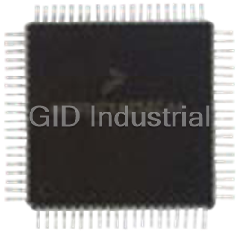



What they say about us
FANTASTIC RESOURCE
One of our top priorities is maintaining our business with precision, and we are constantly looking for affiliates that can help us achieve our goal. With the aid of GID Industrial, our obsolete product management has never been more efficient. They have been a great resource to our company, and have quickly become a go-to supplier on our list!
Bucher Emhart Glass
EXCELLENT SERVICE
With our strict fundamentals and high expectations, we were surprised when we came across GID Industrial and their competitive pricing. When we approached them with our issue, they were incredibly confident in being able to provide us with a seamless solution at the best price for us. GID Industrial quickly understood our needs and provided us with excellent service, as well as fully tested product to ensure what we received would be the right fit for our company.
Fuji
HARD TO FIND A BETTER PROVIDER
Our company provides services to aid in the manufacture of technological products, such as semiconductors and flat panel displays, and often searching for distributors of obsolete product we require can waste time and money. Finding GID Industrial proved to be a great asset to our company, with cost effective solutions and superior knowledge on all of their materials, it’d be hard to find a better provider of obsolete or hard to find products.
Applied Materials
CONSISTENTLY DELIVERS QUALITY SOLUTIONS
Over the years, the equipment used in our company becomes discontinued, but they’re still of great use to us and our customers. Once these products are no longer available through the manufacturer, finding a reliable, quick supplier is a necessity, and luckily for us, GID Industrial has provided the most trustworthy, quality solutions to our obsolete component needs.
Nidec Vamco
TERRIFIC RESOURCE
This company has been a terrific help to us (I work for Trican Well Service) in sourcing the Micron Ram Memory we needed for our Siemens computers. Great service! And great pricing! I know when the product is shipping and when it will arrive, all the way through the ordering process.
Trican Well Service
GO TO SOURCE
When I can't find an obsolete part, I first call GID and they'll come up with my parts every time. Great customer service and follow up as well. Scott emails me from time to time to touch base and see if we're having trouble finding something.....which is often with our 25 yr old equipment.
ConAgra Foods