

 Manufacturers
MARCONI COMMUNICATIONS 1231V2
Description
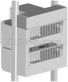
Marconi 1231V2 Spec. No. 582122500 Vortex -48 Volts DC 1200A Max Per Bay, 50A PCU or 65A per PCU.
Part Number
1231V2
Price
Request Quote
Manufacturer
MARCONI COMMUNICATIONS
Lead Time
Request Quote
Category
Rectifiers
Specifications
Access
Front
Accessories
PCU Shelf Class B Filter, PCU Shelf High AC Disconnect, PCU Shelf AC Input Line Cords, Vortex WinLink Hardware (Modem), Vortex WinLink Software
Color
Off-White (Lorain Spec. M500-117)
Control
Microprocessor
Environment
50°C
Family
Vortex
Framework Type
Relay Rack
Model
1231V2
Mounting Depth
18 Inches
Mounting Width
23 Inches per Bay
Options
PCU Intelligence Shelf, PCU Expansion Shelf, V50B50 PCU, V65B50 PCU
Output Voltage
-48 Volts DC
PCU
50 amperes or 65 amperes, per PCU
Spec. No.
582122500
Supplemental Bay(s)
Up to two (2) available
System
1200 amperes, maximum, per bay
Datasheet

Extracted Text
SAG582122500 System Application Guide Spec. No. 582122500 (Model 1231V2) Issue AH, July 31, 2008 Home SYSTEM OVERVIEW Description: This system provides a solution to replace traditional power with power ® derived from the Vortex platform, or to expand existing Vortex Power Systems (VPS’s) to meet additional power needs. A VPS typically consists of ... • one front access VPS Intelligence Shelf, which houses Power Conversion Units (PCU’s). Also includes the Meter-Control-Alarm (MCA) assembly, which controls the operation of up to fifty-six (56) PCU’s, and provides system metering, control, and alarm functions. • one or more optional front access VPS Expansion Shelves, each of which houses PCU’s. • PCU’s which provide load power, List 1 and 3 Shown battery float current, and battery List 2 and 4 Similar (no recharge current during normal Intelligence Shelf) operating conditions. Family: Vortex Spec. No.: 582122500 Model: 1231V2 Output Voltage: -48 Volts DC Output Capacity System: 1200 amperes, maximum, per bay PCU: 50 amperes or 65 amperes, per PCU Framework Type: Relay Rack Mounting Width: 23 Inches per Bay Mounting Depth: 18 Inches Access: Front Supplemental Bay(s): Up to two (2) available Control: Microprocessor Color: Off-White (Lorain Spec. M500-117) Options: PCU Intelligence Shelf, PCU Expansion Shelf, V50B50 PCU, V65B50 PCU List 5 Shown Accessories: PCU Shelf Class B Filter, PCU Shelf High AC List 6 Similar Disconnect, PCU Shelf AC Input Line Cords, Vortex WinLink Hardware (Modem), Vortex WinLink Software Environment: 50°C Page 1 of 24 This document is property of Emerson Network Power, Energy Systems, North America, Inc. and contains confidential and proprietary information owned by Emerson Network Power, Energy Systems, North America, Inc. Any copying, use, or disclosure of it without the written permission of Emerson Network Power, Energy Systems, North America, Inc. is strictly prohibited. SAG582122500 System Application Guide Issue AH, July 31, 2008 Spec. No. 582122500 (Model 1231V2) Home 582122500 (Lists 1 through 4) Shunt POD Card (Inside) Common Equipment (Lists 1, 2, 3, and 4) Vortex WinLink Software (List 73) Vortex WinLink Hardware (Modem) (List 72) PCU Intelligence Shelf Interface (List 7) (used w/ Lists 1 and 3) AC Input Line Cords (List 32) Class B Filter or High AC Disconnect (List 24 or 27) V50B50 PCU or V65B50 PCU (List 21 or 22) PCU Expansion Shelf Interface (List 8) (used w/ Lists 1, 2, 3, and 4) Lists 1 and 3 Shown Lists 2 and 4 Similar (no Intelligence Shelf) SEE ALSO System Overview Table of Contents List Structure Table Lugs Relay Rack Options Replacement Cables List of Parts Dimensional Drawings Related Documentation Page 2 of 24 This document is property of Emerson Network Power, Energy Systems, North America, Inc. and contains confidential and proprietary information owned by Emerson Network Power, Energy Systems, North America, Inc. Any copying, use, or disclosure of it without the written permission of Emerson Network Power, Energy Systems, North America, Inc. is strictly prohibited. System Application Guide SAG582122500 Spec. No. 582122500 (Model 1231V2) Issue AH, July 31, 2008 Home 582122500 (Lists 5 and 6) Shunt POD Card (Inside) Common Equipment (Lists 5 and 6) Vortex WinLink Software (List 73) Vortex WinLink Hardware (Modem) (List 72) PCU Intelligence Shelf Interface (List 7) (used w/ Lists 5 and 6) Class B Filter or High AC Disconnect (List 24 or 27) V50B50 PCU (List 21) PCU Expansion Shelf Interface (List 8) (used w/ Lists 5 and 6) List 5 Shown Mounting Frame List 6 Similar (P/O List 5 only) SEE ALSO System Overview Table of Contents List Structure Table Lugs Relay Rack Options Replacement Cables List of Parts Dimensional Drawings Related Documentation Page 3 of 24 This document is property of Emerson Network Power, Energy Systems, North America, Inc. and contains confidential and proprietary information owned by Emerson Network Power, Energy Systems, North America, Inc. Any copying, use, or disclosure of it without the written permission of Emerson Network Power, Energy Systems, North America, Inc. is strictly prohibited. SAG582122500 System Application Guide Issue AH, July 31, 2008 Spec. No. 582122500 (Model 1231V2) TABLE OF CONTENTS Picture System List Accessory List of Physical Size Related Overview Information Information Parts Information Documentation Lists 1-4 Lists 5-6 SYSTEM OVERVIEW................................................................................................................................................ 1 TABLE OF CONTENTS............................................................................................................................................ 4 LIST INFORMATION................................................................................................................................................. 5 List Structure........................................................................................................................................................ 5 List Descriptions.................................................................................................................................................. 6 List 1: Common Equipment for Main Power Bay (Ship Loose)......................................................................... 6 List 2: Common Equipment for Supplemental Power Bay (Ship Loose)........................................................... 6 List 3: Common Equipment for Main Power Bay (Factory Mounted in a Relay Rack) ..................................... 7 List 4: Common Equipment for Supplemental Power Bay (Factory Mounted in a Relay Rack) ....................... 7 List 5: Common Equipment for Main Power Bay Mounted on Shipping Frame................................................ 8 List 6: Common Equipment for Main Power Bay (Factory Mounted in a Relay Rack) ..................................... 8 List 7: Interface Components for One (1) PCU Intelligence Shelf..................................................................... 9 List 8: Interface Components for One (1) PCU Expansion Shelf...................................................................... 9 List 21: V50B50 PCU ...................................................................................................................................... 10 List 22: V65B50 PCU ...................................................................................................................................... 10 List 24: Optional PCU Shelf Class B Filter ...................................................................................................... 10 List 27: Optional PCU Shelf High AC Input Voltage Disconnect and Reconnect ........................................... 10 List 32: PCU Shelf AC Input Line Cords ......................................................................................................... 11 List 72: Vortex® WinLink Hardware (Modem Interface).................................................................................. 11 List 73: Vortex® WinLink Software.................................................................................................................. 11 ACCESSORY INFORMATION ............................................................................................................................... 12 Lugs..................................................................................................................................................................... 12 Output Lugs...................................................................................................................................................... 12 Lug and Wire Selection Table .......................................................................................................................... 13 Standard Crimp Lug Part Numbers.................................................................................................................. 14 Relay Rack Options (for use with Lists 3, 4, and 6 only) ............................................................................... 15 Replacement Cables.......................................................................................................................................... 16 Optional Cables.................................................................................................................................................. 16 LIST OF PARTS...................................................................................................................................................... 17 PHYSICAL SIZE INFORMATION........................................................................................................................... 19 Overall Dimensions - Lists 1-4.......................................................................................................................... 19 Overall Dimensions - Lists 5-6.......................................................................................................................... 20 Output Busbar Dimensions - Lists 1-4 ............................................................................................................ 21 Output Busbar Dimensions - Lists 5-6 ............................................................................................................ 22 RELATED DOCUMENTATION............................................................................................................................... 23 REVISION RECORD............................................................................................................................................... 24 Page 4 of 24 This document is property of Emerson Network Power, Energy Systems, North America, Inc. and contains confidential and proprietary information owned by Emerson Network Power, Energy Systems, North America, Inc. Any copying, use, or disclosure of it without the written permission of Emerson Network Power, Energy Systems, North America, Inc. is strictly prohibited. System Application Guide SAG582122500 Spec. No. 582122500 (Model 1231V2) Issue AH, July 31, 2008 Home LIST INFORMATION List Structure Mounting Positions List Part Number Description Number (1U = 1-3/4”) 1 1 58212250001 Common Equipment, Main Bay (Ship Loose) 3U 1 2 58212250002 Common Equipment, Supplemental Bay (Ship Loose) 3U Common Equipment, Main Bay 1 3 58212250003 3U (Factory Installed in Specified Relay Rack) Common Equipment, Supplemental Bay 1 4 58212250004 3U (Factory Installed in Specified Relay Rack) Common Equipment, Main Bay, 2 5 58212250005 19U Mounted on Shipping Frame Common Equipment, Main Bay 1 6 58212250006 5U (Factory Installed in Specified Relay Rack) 7 58212250007 Interface Components for PCU Intelligence Shelf 6U 8 58212250008 Interface Components for PCU Expansion Shelf 6U 21 58212250021 V50B50 PCU for V200ICAB and V200ECAB Shelves -- 22 58212250022 V65B50 PCU for V260ICAB and V260ECAB Shelves -- 24 58212250024 Class B Filter for PCU Shelves -- 27 58212250027 High AC Disconnect for PCU Shelves -- 32 58212250032 AC Input Line Cords (Individual PCU Feeds) for PCU Shelves -- 72 58212250072 Vortex WinLink Hardware (Modem) for PCU Intelligence Shelf -- 73 58212250073 Vortex WinLink Software -- 1 Lists 1-4, and 6: Mounting Positions Height does not include PCU Shelves. 2 List 5: Mounting Positions Height includes two (2) PCU Shelves. Page 5 of 24 This document is property of Emerson Network Power, Energy Systems, North America, Inc. and contains confidential and proprietary information owned by Emerson Network Power, Energy Systems, North America, Inc. Any copying, use, or disclosure of it without the written permission of Emerson Network Power, Energy Systems, North America, Inc. is strictly prohibited. SAG582122500 System Application Guide Issue AH, July 31, 2008 Spec. No. 582122500 (Model 1231V2) Home List Descriptions List 1: Common Equipment for List of Parts Main Power Bay (Ship Loose) Features ♦ Provides output lead termination busbars for connection of customer DC power leads. ♦ Provides a shunt POD circuit card (433800164) to allow current monitoring of an external load shunt. The Shunt POD interfaces with the VPS's MCA for remote shunt monitoring. ♦ Provides a “Connector Assembly” circuit card for external alarm, reference, and control connections; and system interconnects. ♦ Includes 60’ long alarm extension cable, Part No. 421630900, for customer connections to VPS Intelligence Shelf external alarm and control circuits. Restrictions The system can consist of a main power bay, and up to two (2) supplemental power bays. Ordering Notes 1) Components shipped loose for mounting on a customer provided relay rack. 2) Order PCU Shelf(s) as required per Lists 7 and 8. 3) Order PCU Shelf options as required per Lists 24 or 27 and 32; and the appropriate PCU Shelf Power Data Sheet. 4) Order PCU's as required per List 21 or 22. 5) Order Vortex WinLink Hardware and Software as required per List 72 and 73. 6) Order output lugs as required per CRIMP LUGS table. List 2: Common Equipment for List of Parts Supplemental Power Bay (Ship Loose) Features ♦ Provides output lead termination busbars for connection of customer DC power leads. ♦ Includes 25’ long interbay cable, Part No. 100575. Restrictions The system can consist of a main power bay, and up to two (2) supplemental power bays. Ordering Notes 1) Components shipped loose for mounting on a customer provided relay rack. 2) Order PCU Shelf(s) as required per List 8. 3) Order PCU Shelf options as required per Lists 24 or 27 and 32; and the appropriate PCU Shelf Power Data Sheet. 4) Order PCU's as required per List 21 or 22. 5) Order output lugs as required per CRIMP LUGS table. Page 6 of 24 This document is property of Emerson Network Power, Energy Systems, North America, Inc. and contains confidential and proprietary information owned by Emerson Network Power, Energy Systems, North America, Inc. Any copying, use, or disclosure of it without the written permission of Emerson Network Power, Energy Systems, North America, Inc. is strictly prohibited. System Application Guide SAG582122500 Spec. No. 582122500 (Model 1231V2) Issue AH, July 31, 2008 Home List 3: Common Equipment for Main Power List of Parts Bay (Factory Mounted in a Relay Rack) Features ♦ Provides output lead termination busbars for connection of customer DC power leads. ♦ Provides a shunt POD circuit card (433800164) to allow current monitoring of an external load shunt. The Shunt POD interfaces with the VPS's MCA for remote shunt monitoring. ♦ Provides a “Connector Assembly” circuit card for external alarm, reference, and control connections; and system interconnects. ♦ Includes 60’ long alarm extension cable, Part No. 421630900, for customer connections to VPS Intelligence Shelf external alarm and control circuits. Restrictions The system can consist of a main power bay, and up to two (2) supplemental power bays. Ordering Notes 1) Factory mounted in relay rack ordered per RELAY RACK OPTIONS table. 2) Order PCU Shelf(s) as required per Lists 7 and 8. 3) Order PCU Shelf options as required per Lists 24 or 27 and 32; and the appropriate PCU Shelf Power Data Sheet. 4) Order PCU's as required per List 21 or 22. 5) Order Vortex WinLink Hardware and Software as required per List 72 and 73. 6) Order output lugs as required per CRIMP LUGS table. List 4: Common Equipment for Supplemental List of Parts Power Bay (Factory Mounted in a Relay Rack) Features ♦ Provides output lead termination busbars for connection of customer DC power leads. ♦ Includes 25’ long interbay cable, Part No. 100575. Restrictions The system can consist of a main power bay, and up to two (2) supplemental power bays. Ordering Notes 1) Factory mounted in relay rack ordered per RELAY RACK OPTIONS table. 2) Order PCU Shelf(s) as required per List 8. 3) Order PCU Shelf options as required per Lists 24 or 27 and 32; and the appropriate PCU Shelf Power Data Sheet. 4) Order PCU's as required per List 21 or 22. 5) Order output lugs as required per CRIMP LUGS table. Page 7 of 24 This document is property of Emerson Network Power, Energy Systems, North America, Inc. and contains confidential and proprietary information owned by Emerson Network Power, Energy Systems, North America, Inc. Any copying, use, or disclosure of it without the written permission of Emerson Network Power, Energy Systems, North America, Inc. is strictly prohibited. SAG582122500 System Application Guide Issue AH, July 31, 2008 Spec. No. 582122500 (Model 1231V2) Home List 5: Common Equipment for Main Power Bay List of Parts Mounted on Shipping Frame Features ♦ All Equipment Cabinets Mounted to a Shipping Frame. ♦ Provides output lead termination busbars for connection of customer DC power leads. ♦ Provides 800A Internal Load Shunt. ♦ Provides a shunt POD circuit card (433800164) to allow current monitoring of the internal load shunt. The Shunt POD interfaces with the VPS's MCA for shunt monitoring. ♦ Provides a “Connector Assembly” circuit card for external alarm, reference, and control connections; and system interconnects. ♦ Includes 60’ long alarm extension cable, Part No. 421630900, for customer connections to VPS Intelligence Shelf external alarm and control circuits. Restrictions The system consists of a main power bay only. Ordering Notes 1) Components mounted on a shipping frame for mounting onto a customer provided relay rack. 2) Order PCU Shelf(s) as required per Lists 7 and 8. 3) Order PCU Shelf options as required per Lists 24 or 27; and the appropriate PCU Shelf Power Data Sheet. 4) Order PCU's as required per List 21. 5) Order Vortex WinLink Hardware and Software as required per List 72 and 73. 6) Order output lugs as required per CRIMP LUGS table. List 6: Common Equipment for Main Power List of Parts Bay (Factory Mounted in a Relay Rack) Features ♦ Provides output lead termination busbars for connection of customer DC power leads. ♦ Provides 800A Internal Load Shunt. ♦ Provides a shunt POD circuit card (433800164) to allow current monitoring of the internal load shunt. The Shunt POD interfaces with the VPS's MCA for shunt monitoring. ♦ Provides a “Connector Assembly” circuit card for external alarm, reference, and control connections; and system interconnects. ♦ Includes 60’ long alarm extension cable, Part No. 421630900, for customer connections to VPS Intelligence Shelf external alarm and control circuits. Restrictions The system consists of a main power bay only. Ordering Notes 1) Factory mounted in relay rack ordered per RELAY RACK OPTIONS table. 2) Order PCU Shelf(s) as required per Lists 7 and 8. Page 8 of 24 This document is property of Emerson Network Power, Energy Systems, North America, Inc. and contains confidential and proprietary information owned by Emerson Network Power, Energy Systems, North America, Inc. Any copying, use, or disclosure of it without the written permission of Emerson Network Power, Energy Systems, North America, Inc. is strictly prohibited. System Application Guide SAG582122500 Spec. No. 582122500 (Model 1231V2) Issue AH, July 31, 2008 Home 3) Order PCU Shelf options as required per Lists 24 or 27; and the appropriate PCU Shelf Power Data Sheet. 4) Order PCU's as required per List 21. 5) Order Vortex WinLink Hardware and Software as required per List 72 and 73. 6) Order output lugs as required per CRIMP LUGS table. List 7: Interface Components for One (1) PCU Intelligence Shelf List of Parts Features ♦ Provides components to add one (1) PCU Intelligence Shelf to the power system. Spec. No. 588700701 or 588703600 for Lists 1, 3, 5 and 6. Spec. No. 588704200 for Lists 5 and 6. ♦ Includes two interconnect cables, Part Nos. 421868200 and 100573. Restrictions Includes PCU Shelf interconnect components only. Only one (1) PCU Intelligence Shelf required per system. Must be installed in main bay (List 1, 3, 5, or 6). Due to AC input connection routing, only one VPS Expansion Shelf (Spec No. 588704300) may be mounted directly below VPS Intelligence Shelf (Spec. No. 588704200). Ordering Notes 1) Order PCU Shelf as required per PD588700701/PD588700801 or PD588703600/PD588703700 (Lists 1, 3, 5 and 6), or PD588704200/PD588704300 (Lists 5 and 6). 2) Order PCU Shelf options as required per Lists 24 or 27, 32, and 72; and PD588700701/PD588700801, or PD588703600/PD588703700, or PD588704200/PD588704300. 3) Order PCU's as required per List 21 or 22. List 8: Interface Components for One (1) PCU Expansion Shelf List of Parts Features ♦ Provides components to add one (1) PCU Expansion Shelf to the power system. Spec. No. 588700801 or 588703700 for Lists 1 through 6. Spec. No. 588704300 for Lists 5 and 6. ♦ Includes two (2) 347177800 shelf interconnect busbars. Restrictions Includes PCU Shelf interconnect components only. Due to AC input connection routing, only one VPS Expansion Shelf (Spec No. 588704300) may be mounted directly below VPS Intelligence Shelf (Spec. No. 588704200). Ordering Notes 1) Order PCU Shelf as required per PD588700701/PD588700801 or PD588703600/PD588703700 (Lists 1 through 6), or PD588704200/PD588704300 (Lists 5 and 6). 2) Order PCU Shelf options as required per Lists 24 or 27, 32, and 72; and PD588700701/PD588700801, or PD588703600/PD588703700, or PD588704200/PD588704300. 3) Order PCU's as required per List 21 or 22. Page 9 of 24 This document is property of Emerson Network Power, Energy Systems, North America, Inc. and contains confidential and proprietary information owned by Emerson Network Power, Energy Systems, North America, Inc. Any copying, use, or disclosure of it without the written permission of Emerson Network Power, Energy Systems, North America, Inc. is strictly prohibited. SAG582122500 System Application Guide Issue AH, July 31, 2008 Spec. No. 582122500 (Model 1231V2) Home List of Parts List 21: V50B50 PCU Features ♦ Provides one (1) Model V50B50 (-48V/50A), Spec. No. 486529902, PCU. Restrictions For use in Spec. No. 588700701, 588700801, 588704200, and 588704300 PCU Shelves only. Ordering Notes 1) Each shelf holds up to four (4) PCU's. List of Parts List 22: V65B50 PCU Features ♦ Provides one (1) Model V65B50 (-48V/65A), Spec. No. 486531800, PCU. Restrictions For use in Spec. No. 588703600 and 588703700 PCU Shelves only. Ordering Notes 1) Each shelf holds up to four (4) PCU's. List of Parts List 24: Optional PCU Shelf Class B Filter Features ♦ Consists of four Part No. 433800199 Input Filter Assemblies (one for each PCU mounting position in a single shelf) and capacitor pigtail assemblies. Refer to PD588700701/PD588700801, PD588703600/PD588703700, or PD588704200/PD588704300 for further description. Restrictions Cannot be installed if 582122500 List 27 ordered. The PCU Shelf can only accommodate 582122500 List 24 or 582122500 List 27, not both. Ordering Notes 1) Specify one (1) List 24 per PCU Shelf. List of Parts List 27: Optional PCU Shelf High AC Input Voltage Disconnect and Reconnect Features ♦ Consists of four Part No. 486390500 High AC Input Voltage Disconnect and Reconnect circuit card assemblies (one for each PCU mounting position in a single shelf). Refer to PD588700701/PD588700801, PD588703600/PD588703700, or PD588704200/PD588704300 for further description. Restrictions Cannot be installed if 582122500 List 24 ordered. The PCU Shelf can only accommodate 582122500 List 24 or 582122500 List 27, not both. Ordering Notes 1) Specify one (1) List 27 per PCU Shelf. Page 10 of 24 This document is property of Emerson Network Power, Energy Systems, North America, Inc. and contains confidential and proprietary information owned by Emerson Network Power, Energy Systems, North America, Inc. Any copying, use, or disclosure of it without the written permission of Emerson Network Power, Energy Systems, North America, Inc. is strictly prohibited. System Application Guide SAG582122500 Spec. No. 582122500 (Model 1231V2) Issue AH, July 31, 2008 Home List 32: PCU Shelf AC Input Line Cords List of Parts Features ♦ Consists of four (4) 14’ long AC input line cords (one for each PCU mounting position in a single shelf). Refer to PD588700701/PD588700801 or PD588703600/PD588703700 for further description. Restrictions For use with PCU Shelves Spec. Nos. 588700701, 588700801, 588703600, and 588703700 only. CANNOT be used with PCU Shelves Spec. Nos. 588704200 and 588704300. Must be used with the standard PCU Shelf AC input housing assembly. Cannot be used with the optional PCU Shelf single or dual feed AC input housing assemblies. Ordering Notes 1) Specify one (1) List 32 per PCU Shelf. List 72: Vortex® WinLink Hardware (Modem Interface) List of Parts Features ♦ Provides Spec. No. 483215200 which consists of a 2400 bits/s Modem circuit card, Spec. No. 486781300, plus associated hardware. ♦ This option plugs into the side of the VPS Intelligence Shelf. Restrictions Only one interface option (Vortex WinLink Hardware or RS-485 can be installed on the VPS Intelligence Shelf. Do not order this option when the VPS is to be interfaced with a Vortex SMART or SMART DGU. Ordering Notes 1) Order this option for each VPS (MCA) to be accessed via Vortex WinLink Software. List of Parts List 73: Vortex® WinLink Software Features ♦ Provides Spec. No. 041182000 (Vortex WinLink Software). ♦ Vortex WinLink Software provides the user the ability to remotely communicate with multiple VPS's equipped with the Vortex WinLink Hardware option. Only one VPS can be remotely connected at a time. This allows a user to remotely monitor, control, and adjust the VPS via Vortex WinLink. Remote communication is done over dial-up phone lines when the VPS is equipped with the modem interface (List 72). ♦ With Vortex WinLink Software, the same tasks accomplished via the VPS's MCA local interface pad can be done remotely. This includes alarm monitoring, voltage/current monitoring, and adjustment of alarm and control circuits. ♦ The Vortex WinLink software, Spec. No. 041182000, runs under the Windows 95/NT platform. Ordering Notes 1) Only one List 73 required for each computer installation. Page 11 of 24 This document is property of Emerson Network Power, Energy Systems, North America, Inc. and contains confidential and proprietary information owned by Emerson Network Power, Energy Systems, North America, Inc. Any copying, use, or disclosure of it without the written permission of Emerson Network Power, Energy Systems, North America, Inc. is strictly prohibited. SAG582122500 System Application Guide Issue AH, July 31, 2008 Spec. No. 582122500 (Model 1231V2) Home ACCESSORY INFORMATION Lugs All lugs for customer connections must be ordered separately. For lug selection, refer to the CRIMP LUG TABLE. For additional lug information, refer to Drawings 031110100 through 031110300. Output Lugs Output lug requirements are determined by site requirements. Output conductors and lugs are connected to the main and supplemental bays’ output busbars. These busbars are provided with holes for installation of customer provided two hole lugs with 1 inch centers and 3/8 inch bolt clearance holes. Customer must provide lug mounting bolts and additional hardware. For lug mounting hole size and spacing dimensions, refer to DIMENSIONS. The output busbars are designed to accommodate the lugs listed in Table 1. Use Table 1 to select recommended output lead sizes and lugs for various bay output current capacities. Wire sizes based on recommendations of the National Electrical Code Table 310-16 for copper wire at 90°C conductor temperature, operating in ambient of 50°C. For operation in other ambients, see Table 310-16 of the National Electrical Code. Recommended wire sizes are sufficient to restrict voltage drop to the values listed in Table 1 at stated bay output current for the loop lengths listed in Table 1. Loop length is the sum of the lengths of the positive and negative leads. Page 12 of 24 This document is property of Emerson Network Power, Energy Systems, North America, Inc. and contains confidential and proprietary information owned by Emerson Network Power, Energy Systems, North America, Inc. Any copying, use, or disclosure of it without the written permission of Emerson Network Power, Energy Systems, North America, Inc. is strictly prohibited. System Application Guide SAG582122500 Spec. No. 582122500 (Model 1231V2) Issue AH, July 31, 2008 Home Lug and Wire Selection Table LUG AND WIRE SIZE SELECTION (Two-Hole Lug, 3/8" Bolt Clearance Hole, 1" Centers) Loop Recommended Crimp Lug Length* Bay’s Recm Output Wire 0.25 1.0 Wire Current Size* Volt Volt Stranding Part No. Drop Drop Class (Qty. 6) 245347400 1200A 18 ft. 75 ft. B 4/0 Ga. (Burndy YA28L-2TC38) (Qty. 5) 245347400 1000A 18 ft. 75 ft. B 4/0 Ga. (Burndy YA28L-2TC38) (Qty. 4) 245347400 800A 18 ft. 75 ft. B 4/0 Ga. (Burndy YA28L-2TC38) (Qty. 3) 245347400 600A 18 ft. 75 ft. B 4/0 Ga. (Burndy YA28L-2TC38) (Qty. 2) 245347400 400A 18 ft. 75 ft. B 4/0 Ga. (Burndy YA28L-2TC38) (Qty. 1) 245347400 200A 18 ft. 75 ft. B 4/0 Ga. (Burndy YA28L-2TC38) * Refer to OUTPUT LUGS for applicable information. Table 1 Recommended Output Lead Sizes and Crimp Lugs Page 13 of 24 This document is property of Emerson Network Power, Energy Systems, North America, Inc. and contains confidential and proprietary information owned by Emerson Network Power, Energy Systems, North America, Inc. Any copying, use, or disclosure of it without the written permission of Emerson Network Power, Energy Systems, North America, Inc. is strictly prohibited. SAG582122500 System Application Guide Issue AH, July 31, 2008 Spec. No. 582122500 (Model 1231V2) Home Standard Crimp Lug Part Numbers CRIMP LUGS (Two-Hole, 3/8” Bolt Clearance Hole, 1.000” Centers) LEAD SIZE (Ga.) PART NUMBER 8 245349800 6 245349900 4 245350000 2 245348200 1/0 245347100 2/0 245347200 3/0 245347300 4/0 245347400 250 MCM 245347500 300 MCM 245347600 350 MCM 245347700 400 MCM 245347800 500 MCM 245347900 600 MCM 245348000 750 MCM 245348100 Page 14 of 24 This document is property of Emerson Network Power, Energy Systems, North America, Inc. and contains confidential and proprietary information owned by Emerson Network Power, Energy Systems, North America, Inc. Any copying, use, or disclosure of it without the written permission of Emerson Network Power, Energy Systems, North America, Inc. is strictly prohibited. System Application Guide SAG582122500 Spec. No. 582122500 (Model 1231V2) Issue AH, July 31, 2008 Home Relay Rack Options (for use with Lists 3, 4, and 6 only) This system is factory mounted to the relay rack specified when ordered (List 3, 4, and 6 only). The following relay racks are available: AVAILABLE PART MOUNTING POSITIONS SIZE NOTES NUMBER 1U = 1-3/4” 500091 25-1/8”H x 23”W 13U Allows for mounting of one (1) VPS PCU Shelf 377333500 27-1/2”H x 23”W 14U Allows for mounting of one (1) VPS PCU Shelf Allows for mounting of two (2) VPS PCU 377333600 35-7/16”H x 23”W 19U Shelves Allows for mounting of two (2) VPS PCU 377332900 39-1/8”H x 23”W 21U Shelves with List 6 or three (3) with Lists 3 and 4 Seismic (complies with Bellcore Seismic Zone 4 requirements) 377334300 7’0”H x 23”W 45U Allows for mounting of up to six (6) VPS PCU Shelves Allows for mounting of up to six (6) VPS PCU 412404600 7’0”H x 23”W 45U Shelves Allows for mounting of up to six (6) VPS PCU 412404700 7’6”H x 23”W 48U Shelves Note 1: For additional relay rack options, see drawing 412202500. Page 15 of 24 This document is property of Emerson Network Power, Energy Systems, North America, Inc. and contains confidential and proprietary information owned by Emerson Network Power, Energy Systems, North America, Inc. Any copying, use, or disclosure of it without the written permission of Emerson Network Power, Energy Systems, North America, Inc. is strictly prohibited. SAG582122500 System Application Guide Issue AH, July 31, 2008 Spec. No. 582122500 (Model 1231V2) Home Replacement Cables Ordering Notes 1) Standard External Alarm Interconnect Cable: Provides mating connector and sixty (60) foot long cable as a convenient method of connecting the external alarm wiring of the VPS Intelligence Shelf to customer circuits. Connects to J8 on the VPS Intelligence Shelf and provides 28 gauge leads to be spliced to customer leads. For a replacement cable, order Part No. 421630900 (60'0" cable). Note: For a longer cable, see Optional Cables below. 2) VPS to VPS Interconnect Cable: Provides mating connectors and cable as a convenient method of connecting the alarm, reference, and control leads of a VPS to a subsequent VPS. Connects between J1 on "Connector Assembly" circuit card 500441 located within the VPS and J2 on "Connector Assembly" circuit card 500441 located within the subsequent VPS. For a replacement cable, order Part No. 100916 (25'0" cable). 3) "Connector Assembly" Circuit Card to VPS Intelligence Shelf (MCA) Interconnect Cable: Provides mating connectors and cable as a convenient method of connecting the alarm, reference, and control terminals provided on the "Connector Assembly" circuit card for customer connections and system interface to the MCA in the VPS Intelligence Shelf. Connects between J2 on "Connector Assembly" circuit card 500441 located in the main VPS and J9 on the VPS Intelligence Shelf located within the same rack. For a replacement cable, order Part No. 421868200 (13.5" cable). 4) "Connector Assembly" Circuit Card to VPS Intelligence Shelf (MCA/PCU's) Interconnect Cable: Provides mating connectors and cable as a convenient method for MCA signal interconnection between the terminals provided on the "Connector Assembly" circuit card for customer connections and interface to PCU's located in other racks. Connects between J8, J9, or J10 on "Connector Assembly" circuit card 500441 located in the main VPS and J11 or J12 on the VPS Intelligence Shelf located within the same rack. For a replacement cable, order Part No. 100573 (11.5" cable). 5) VPS Intelligence and Expansion Shelves Interconnect Cable (when located in same rack): Provides mating connectors and cable as a convenient method for MCA signal interconnection between the VPS Intelligence Shelf and a VPS Expansion Shelf or between two VPS Expansion Shelves, located in the same rack. Connects between J11 and J12 of each shelf. A cable is provided with each VPS Expansion Shelf. For a replacement cable, order Part No. 100573 (11.5" cable). 6) VPS Intelligence and Expansion Shelves Interconnect Cable (when located in separate racks): Provides mating connectors and cable as a convenient method for MCA signal interconnection between VPS PCU Shelves located in separate racks. VPS PCU Shelves in the same rack are interconnected as described in 5). The VPS Intelligence Shelf is interconnected to the "Connector Assembly" circuit card as described in 4). Up to two additional racks of PCU Shelves are interconnected via the "Connector Assembly" circuit card. Each interconnect cable connects between J8, J9, or J10 on "Connector Assembly" circuit card 500441 located in the main VPS and J11 or J12 of the top most VPS PCU Shelf located in a separate rack. For a replacement cable, order Part No. 100575 (25'0" cable). A 12'0" cable is also available, Part No. 100574. Optional Cables External Alarm Interconnect Cable, Part no. 521216: Provides mating connector and 100-foot long cable as a convenient method of connecting the external alarm wiring of the VPS Intelligence Shelf to customer circuits. Connects to J8 on the VPS Intelligence Shelf and provides 28 gauge leads to be spliced to customer leads. Provides alarm relay connections only. Does not provide external control connections for Remote HVSD, Remote Emergency Shutdown, or Remote Test/Equalize functions. Can be used in place of the standard 60-ft.alarm cable, Part No. 421630900, when a longer cable is required and external control connections are not required. Page 16 of 24 This document is property of Emerson Network Power, Energy Systems, North America, Inc. and contains confidential and proprietary information owned by Emerson Network Power, Energy Systems, North America, Inc. Any copying, use, or disclosure of it without the written permission of Emerson Network Power, Energy Systems, North America, Inc. is strictly prohibited. System Application Guide SAG582122500 Spec. No. 582122500 (Model 1231V2) Issue AH, July 31, 2008 Home LIST OF PARTS (This Stocklist may not list every component contained in each List.) LIST PART QTY. DESCRIPTION NUMBER NUMBER 1 505287 Shield, E Shape, Rear Busbar 1 505289 Busbar, C Shaped, Neg Bat 1 505290 Busbar, Irregular U Shaped, Pos Bat 1 1 505332 Assy, Alm/Interface 1 505505 Hardware Kit 1 421630900 Cable Assy 1 100575 Cable Assy 1 505169 Panel, Irreg, Busbar Support 1 505286 Panel, Hat Shape, Shunt/Alm Interface 2 1 505287 Shield, E Shape, Rear Busbar 1 505289 Busbar, C Shaped, Neg Bat 1 505290 Busbar, Irregular U Shaped, Pos Bat 1 505505 Hardware Kit 1 505287 Shield, E Shape, Rear Busbar 1 505289 Busbar, C Shaped, Neg Bat 1 505290 Busbar, Irregular U Shaped, Pos Bat 3 1 505332 Assy, Alm/Interface 1 505505 Hardware Kit 1 421630900 Cable Assy 1 100575 Cable Assy 1 505169 Panel, Irreg, Busbar Support 1 505286 Panel, Hat Shape, Shunt/Alm Interface 4 1 505287 Shield, E Shape, Rear Busbar 1 505289 Busbar, C Shaped, Neg Bat 1 505290 Busbar, Irregular U Shaped, Pos Bat 1 505505 Hardware Kit 1 508573 Panel, Mounting Frame 5 1 508586 Assy, Alm/Interface 1 421630900 Cable Assy 1 508586 Assy, Alm/Interface 6 1 421630900 Cable Assy 1 100573 Cable Assy 7 1 505506 Hardware Kit 1 421868200 Cable Assy 8 2 347177800 Busbar & Associated Hardware 21 1 486529902 Rect, Vortex PCU, 48V, 50A 22 1 486531800 Rect, Vortex PCU, 48V, 65A 6 425140100 Pigtail Assy 2 425140400 Pigtail Assy 24 2 425140600 Pigtail Assy 4 433800199 Class B EMI Filter PW Assy 27 4 486390500 High AC Volt Shutdown PW Assy Page 17 of 24 This document is property of Emerson Network Power, Energy Systems, North America, Inc. and contains confidential and proprietary information owned by Emerson Network Power, Energy Systems, North America, Inc. Any copying, use, or disclosure of it without the written permission of Emerson Network Power, Energy Systems, North America, Inc. is strictly prohibited. SAG582122500 System Application Guide Issue AH, July 31, 2008 Spec. No. 582122500 (Model 1231V2) Home LIST PART QTY. DESCRIPTION NUMBER NUMBER 1 104821 Cord, AC Input 1 104836 Cord, AC Input 32 1 104837 Cord, AC Input 1 104838 Cord, AC Input 72 1 483215200 Kit, MCA Modem Install 73 1 041182000 Vortex WinLink Software Page 18 of 24 This document is property of Emerson Network Power, Energy Systems, North America, Inc. and contains confidential and proprietary information owned by Emerson Network Power, Energy Systems, North America, Inc. Any copying, use, or disclosure of it without the written permission of Emerson Network Power, Energy Systems, North America, Inc. is strictly prohibited. System Application Guide SAG582122500 Spec. No. 582122500 (Model 1231V2) Issue AH, July 31, 2008 Home PHYSICAL SIZE INFORMATION Overall Dimensions - Lists 1-4 TOP VIEW 5.25 24.31 17.50 TOP PANEL LEFT SIDE VIEW FRONT VIEW RIGHT SIDE VIEW NOTES : 1. ALL DIMENSIONS ARE IN INCHES UNLESS OTHERWISE SPECIFIED. 2. WEIGHT IN LBS. (TOP PANEL AND BUSBARS ONLY) NET: 25 SHIPPING: 30 (refer to PCU Shelves Power Data Sheets for their weights) 3. FINISH: OFF-WHITE 4. INDICATES VENTILATING GRILLE 5. REFER TO THE PCU SHELVES POWER DATA SHEETS FOR THEIR DIMENSIONS Page 19 of 24 This document is property of Emerson Network Power, Energy Systems, North America, Inc. and contains confidential and proprietary information owned by Emerson Network Power, Energy Systems, North America, Inc. Any copying, use, or disclosure of it without the written permission of Emerson Network Power, Energy Systems, North America, Inc. is strictly prohibited. SAG582122500 System Application Guide Issue AH, July 31, 2008 Spec. No. 582122500 (Model 1231V2) Home Overall Dimensions - Lists 5-6 FRONT VIEW REAR VIEW Mounting Frame (P/O List 5 Only) LEFT SIDE VIEW RIGHT SIDE VIEW 33.25 29.75 NOTES : 17.25 1. ALL DIMENSIONS ARE IN INCHES 24.50 UNLESS OTHERWISE SPECIFIED. 2. WEIGHT IN LBS. (TOP CABINET, TWO PCU SHELVES, EIGHT PCU's, AND SHIPPING FRAME) NET: 207 SHIPPING: 225 3. FINISH: OFF-WHITE 4. INDICATES VENTILATING GRILLE TOP VIEW Page 20 of 24 This document is property of Emerson Network Power, Energy Systems, North America, Inc. and contains confidential and proprietary information owned by Emerson Network Power, Energy Systems, North America, Inc. Any copying, use, or disclosure of it without the written permission of Emerson Network Power, Energy Systems, North America, Inc. is strictly prohibited. System Application Guide SAG582122500 Spec. No. 582122500 (Model 1231V2) Issue AH, July 31, 2008 Home Output Busbar Dimensions - Lists 1-4 3/8" CLEARANCE HOLES, 12 PLACES SUPPLY GND RTN (CUSTOMER MUST SUPPLY -48V +48V LUG MOUNTING BOLTS AND ADDITIONAL HARDWARE) 1.000 1.000 1.250 POS NEG POS NEG REAR VIEW Page 21 of 24 This document is property of Emerson Network Power, Energy Systems, North America, Inc. and contains confidential and proprietary information owned by Emerson Network Power, Energy Systems, North America, Inc. Any copying, use, or disclosure of it without the written permission of Emerson Network Power, Energy Systems, North America, Inc. is strictly prohibited. SAG582122500 System Application Guide Issue AH, July 31, 2008 Spec. No. 582122500 (Model 1231V2) Home Output Busbar Dimensions - Lists 5-6 TO TO TO TO +BATTERY GND BAR DISTR. -BATTERY (GND RTN (GND RTN (SUPPLY (SUPPLY +48V) +48V) -48V) -48V) 1.000 1.000 1.000 1.250 -BAT +BAT GRD DIST FRONT VIEW 3/8" CLEARANCE HOLES, 24 PLACES (CUSTOMER MUST SUPPLY LUG MOUNTING BOLTS AND ADDITIONAL HARDWARE) Components removed in illustration for clarity. Page 22 of 24 This document is property of Emerson Network Power, Energy Systems, North America, Inc. and contains confidential and proprietary information owned by Emerson Network Power, Energy Systems, North America, Inc. Any copying, use, or disclosure of it without the written permission of Emerson Network Power, Energy Systems, North America, Inc. is strictly prohibited. System Application Guide SAG582122500 Spec. No. 582122500 (Model 1231V2) Issue AH, July 31, 2008 Home RELATED DOCUMENTATION VPS Intelligence and Expansion Shelf Power Data Sheets (includes PCU and MCA info): PD588700701/PD588700801 (V200ICAB/V200ECAB) PD588703600/PD588703700 (V260ICAB/V260ECAB) PD588704200/PD588704300 (V200ICAB/V200ECAB) Schematic Diagram: SD582122500 (VPS) SD505332 (Alarm/Interface Panel) SD508586 (Alarm/Interface Panel) SD588700701 (V200ICAB) SD588700801 (V200ECAB) SD588703600 (V260ICAB) SD588703700 (V260ECAB) SD588704200 (V200ICAB) SD588704300 (V200ECAB) Wiring Diagram: T505332 (Alarm/Interface Panel) T508586 (Alarm/Interface Panel) T588700701 (V200ICAB) T588700801 (V200ECAB) T588703600 (V260ICAB) T588703700 (V260ECAB) T588704200 (V200ICAB) T588704300 (V200ECAB) Color MCA Menu Tree: Section 5762 Instructions: Section 5806 (System User Instructions) Section 5878 (System Installation Instructions) Load and Battery Lug Detail Drawings: 031110100 through 031110300 Page 23 of 24 This document is property of Emerson Network Power, Energy Systems, North America, Inc. and contains confidential and proprietary information owned by Emerson Network Power, Energy Systems, North America, Inc. Any copying, use, or disclosure of it without the written permission of Emerson Network Power, Energy Systems, North America, Inc. is strictly prohibited. SAG582122500 System Application Guide Issue AH, July 31, 2008 Spec. No. 582122500 (Model 1231V2) Home REVISION RECORD Change Rev Number Description of Change Date Approved (ECO) AA LLP010235 New 3/7/00 J. Jasko, S. Lewis List 5 and 6 added. 588704200 added to List 7. 588704300 added to List 8. Loop length for AB LLP016262 1/23/01 Steve McWilliams 0.25 volt drop added to Table 1. Revised st ENVIRONMENT statement on 1 page. Spec. No. 588703600 and 588703700 PCU AC LLP033070 8/5/02 John Jasko Shelves added. List 22 PCU added. RELATED DOCUMENTATION section AD LLP036276 09/26/03 John Jasko updated. AE LLP202677 Name/Logo Change. 12/02/04 John Jasko 3/18/05 P. Amato AF LLP201418 Added P/N 521216 cable to Accessories. 3/21/05 J. Kirkpatrick Revised List 7 and 8 features and ordering AG LLP205204 1/20/06 J. Kirkpatrick notes. AH LLP210437 Part number 486529901 now 486529902. 07/31/08 John Jasko Emerson Network Power, Energy Systems, North America, Inc. 1122 F Street / Lorain, Ohio 44052-2293 / (440) 288-1122 In Canada: Emerson Electric Canada Limited 122 Edward St. / St. Thomas, Ontario N5P 1Z2 / (519) 637-4900 In Mexico: Emerson Network Power de Mexico, S.A. de C.V. Apartado Postal 77001 / Mexico 10 D.F., MX 11200 / (525) 576-8277 Page 24 of 24 This document is property of Emerson Network Power, Energy Systems, North America, Inc. and contains confidential and proprietary information owned by Emerson Network Power, Energy Systems, North America, Inc. Any copying, use, or disclosure of it without the written permission of Emerson Network Power, Energy Systems, North America, Inc. is strictly prohibited.
Frequently asked questions
How does Industrial Trading differ from its competitors?

Is there a warranty for the 1231V2?
Which carrier will Industrial Trading use to ship my parts?
Can I buy parts from Industrial Trading if I am outside the USA?
Which payment methods does Industrial Trading accept?
Why buy from GID?

Quality
We are industry veterans who take pride in our work

Protection
Avoid the dangers of risky trading in the gray market

Access
Our network of suppliers is ready and at your disposal

Savings
Maintain legacy systems to prevent costly downtime

Speed
Time is of the essence, and we are respectful of yours
Related Products

Marconi 486529902 SAG582122500 Model 1231V2 V50B50 PCU, Rectifier, Vortex PCU, 48V, 50A
Marconi A12F50 -48VDC, 12 Amp Stand Alone Rectifier
Marconi A50CAB Rectifier - 25-75 amp, -48 VDC Rectifier System with 25 amp rectifier
Marconi Lorain RL50F50 543103900 -48 VDC Rectifier | 50 Amps | Input Taps for 120 (106-127), 208 (18...
RECTIFIER, 65 AMP, FOR MARCONI POWER PLANT
Request a Quote

The quote request has been received
Close

Facing challenges or have inquiries? Feel free to contact us!
Call Us +1-469-283-2440
What they say about us
FANTASTIC RESOURCE
One of our top priorities is maintaining our business with precision, and we are constantly looking for affiliates that can help us achieve our goal. With the aid of GID Industrial, our obsolete product management has never been more efficient. They have been a great resource to our company, and have quickly become a go-to supplier on our list!
Bucher Emhart Glass
EXCELLENT SERVICE
With our strict fundamentals and high expectations, we were surprised when we came across GID Industrial and their competitive pricing. When we approached them with our issue, they were incredibly confident in being able to provide us with a seamless solution at the best price for us. GID Industrial quickly understood our needs and provided us with excellent service, as well as fully tested product to ensure what we received would be the right fit for our company.
Fuji
HARD TO FIND A BETTER PROVIDER
Our company provides services to aid in the manufacture of technological products, such as semiconductors and flat panel displays, and often searching for distributors of obsolete product we require can waste time and money. Finding GID Industrial proved to be a great asset to our company, with cost effective solutions and superior knowledge on all of their materials, it’d be hard to find a better provider of obsolete or hard to find products.
Applied Materials
CONSISTENTLY DELIVERS QUALITY SOLUTIONS
Over the years, the equipment used in our company becomes discontinued, but they’re still of great use to us and our customers. Once these products are no longer available through the manufacturer, finding a reliable, quick supplier is a necessity, and luckily for us, GID Industrial has provided the most trustworthy, quality solutions to our obsolete component needs.
Nidec Vamco
TERRIFIC RESOURCE
This company has been a terrific help to us (I work for Trican Well Service) in sourcing the Micron Ram Memory we needed for our Siemens computers. Great service! And great pricing! I know when the product is shipping and when it will arrive, all the way through the ordering process.
Trican Well Service
GO TO SOURCE
When I can't find an obsolete part, I first call GID and they'll come up with my parts every time. Great customer service and follow up as well. Scott emails me from time to time to touch base and see if we're having trouble finding something.....which is often with our 25 yr old equipment.
ConAgra Foods