

 Manufacturers
M-SYSTEMS MD1150-D16

Description
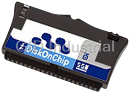
M-System MD1150-D16 Solid State Disks - M-Systems iDiskOnChip 16 MB 40 pin
Part Number
MD1150-D16
Price
Request Quote
Manufacturer
M-SYSTEMS
Lead Time
Request Quote
Category
Solid State Disks
Specifications
Alignments
Vertical; Horizontal, left-oriented; Horizontal, right-oriented
Capacity and Packaging
Available in capacities of 16MB to 1536MB
Current
Active Mode (Max.):60 mA; Idle Mode (Max):2 mA; Sleep mode (max):500 µA
Horizontal version
55.0 x 30.4 x 9.1 (mm) (LxWxH)
IDE Modes
PIO modes 0-4 (True IDE)
iDiskOnChip provides
NAND flash-based technology, High performance, Platform independence, Fast time to market - no driver required, Reed-Solomon code-based EDC/ECC (2 Bits/Page), Wear-Leveling Algorithm: This algorithm guarantees the use of all flash components at the same level of the write/erase cycle, Fast ATA host transfer rates supporting PIO-4 in true IDE mode, IDE Master/Slave modes of operation, 40-pin or 44-pin IDE connector, Vertical and horizontal alignments
Performance
Host Data Transfer Rate: Read: 5 MB/sec; Write:1.5 MB/sec
Power Requirements
Single power supply:5V (± 10%) or 3.3v (± 5%)
Shock
50 G, 3 axes
Sinusoidal Vibration
5g, 7-2000 Hz, 3 axis
System Compatibility
Compatible with devices that support the ATA-4 Attachment (without DMA support) for Disk Drive Standard
Temperature
Operating:0ºC to +70ºC; Storage:-40°C to + 80°C
Vertical version
56.3 x 6.0 x 30.6 (mm) (LxWxH)
Datasheet

Extracted Text
iDiskOnChip (iDOC) Flash Disk with IDE Interface Highlights iDiskOnChip (iDOC) combines advanced and proven DiskOnChip technology with a standard IDE interface to complement the DiskOnChip product line. iDiskOnChip provides: Operating Temperature � NAND flash-based technology � Temperature Range: 0ºC to +70ºC � High performance � Platform independence Environmental Conditions � Fast time to market - no driver required � Storage Temperature: -40°C to + 80°C � Reed-Solomon code-based EDC/ECC (2 � Sinusoidal Vibration: 5g, 7-2000 Hz, 3 axis Bits/Page) � Shock: 50 G, 3 axes � Wear-Leveling Algorithm: This algorithm System Compatibility guarantees the use of all flash components � Compatible with devices that support the at the same level of the write/erase cycle ATA-4 Attachment (without DMA support) � Fast ATA host transfer rates supporting for Disk Drive Standard PIO-4 in true IDE mode Capacity and Packaging � IDE Master/Slave modes of operation � Available in capacities of 16MB to 1536MB � 40-pin or 44-pin IDE connector � Alignments: � Vertical and horizontal alignments � Vertical IDE Modes � Horizontal, left-oriented � Horizontal, right-oriented � PIO modes 0-4 (True IDE) Mechanical dimensions Performance � Vertical version: � Host Data Transfer Rate: � 40-pin: 56.3 x 6.0 x 30.6 (mm) � Read: 5 MB/sec (LxWxH) � Write: 1.5 MB/sec � 44-pin: 53.0 x 6.0 x 31.2 (mm) Power Requirements (LxWxH) � Single power supply: 5V (± 10%) or 3.3v � Horizontal version: (± 5%) � 40-pin: 55.0 x 30.4 x 9.1 (mm) � Current (LxWxH) � Active Mode (Max.): 60 mA � 44-pin: 48.0 x 32.6 x 5.9 (mm) � Idle Mode (Max): 2 mA (LxWxH) � Sleep mode (max): 500 µA 1 Data Sheet, Rev 1.2 91-SR-012-01-8L TABLE OF CONTENTS 1. Introduction ............................................................................................................................... 4 2. Product Overview...................................................................................................................... 5 2.1 Product Description ............................................................................................................5 2.2 Pin Assignment................................................................................................................... 6 2.3 Pin Description ................................................................................................................... 7 3. Theory of Operation .................................................................................................................. 9 3.1 Overview............................................................................................................................. 9 3.2 Controller............................................................................................................................ 9 3.3 Error Detection and Correction........................................................................................... 9 3.4 Wear-Leveling ..................................................................................................................10 4. Installation Requirements ......................................................................................................11 4.1 iDiskOnChip Pin Directions .............................................................................................. 11 4.2 iDiskOnChip Left/Right Orientation, Horizontal Version ................................................... 11 4.3 Electrical Connections for iDiskOnChip............................................................................ 12 4.4 Installing iDiskOnChip in a Two-Drive Configuration (Master/Slave) ............................... 12 4.4.1 Vertical Configuration ......................................................................................................... 12 4.4.2 Horizontal Configuration..................................................................................................... 13 5. Power Management................................................................................................................. 14 6. Specifications .......................................................................................................................... 15 6.1 CE and FCC Compatibility................................................................................................ 15 6.2 Environmental Specifications ........................................................................................... 15 6.2.1 Temperature Ranges ......................................................................................................... 15 6.2.2 Humidity.............................................................................................................................. 15 6.2.3 Shock and Vibration ........................................................................................................... 15 6.2.4 Mean Time between Failures (MTBF)................................................................................ 15 6.2.5 Endurance .......................................................................................................................... 16 6.3 Mechanical Dimensions.................................................................................................... 16 6.3.1 40-Pin Horizontal Version................................................................................................... 16 6.3.2 44-Pin Horizontal Version................................................................................................... 16 6.3.3 40-Pin Vertical Version....................................................................................................... 17 6.3.4 44-Pin Vertical Version....................................................................................................... 17 2 iDiskOnChip (iDOC) Data Sheet, Rev. 1.2 91-SR-012-01-8L 6.4 Electrical Specifications.................................................................................................... 18 6.4.1 Absolute Maximum Ratings................................................................................................ 18 6.4.2 DC Characteristics ............................................................................................................. 18 6.4.3 AC Characteristics..............................................................................................................18 7. Ordering Information............................................................................................................... 20 How to Contact Us ........................................................................................................................ 23 3 iDiskOnChip (iDOC) Data Sheet, Rev. 1.2 91-SR-012-01-8L 1. INTRODUCTION This data sheet includes the following sections: Section 1: Overview of data sheet contents Section 2: Product overview, including brief product description, pin assignment and description Section 3: Theory of operation Section 4: Installation requirements, including electrical cabling and master/slave configurations Section 5: Power management for the various iDiskOnChip operational modes Section 6: Product specifications, including mechanical and electrical Section 7: Product ordering information and available product configurations For additional information on M-Systems’ flash disk products, please contact one of the offices listed on the back page. 4 iDiskOnChip (iDOC) Data Sheet, Rev. 1.2 91-SR-012-01-8L 2. PRODUCT OVERVIEW 2.1 Product Description iDiskOnChip complements the DiskOnChip product line, offering full IDE capabilities, high performance, a built-in ECC system and flexible design options. It can be used in any system with an IDE bus and can work with any operating system, since the driver is handled at the BIOS level. iDiskOnChip is based on NAND flash technology. This technology is superior in its data storage characteristics, featuring the industry’s highest write and erase performance, as well as the highest burst read/write transfer rate. Additionally, NAND flash technology is known for its high density and small die size, with the related cost and real estate benefits. Data integrity is guaranteed through embedded error detection and error correction code (EDC/ECC) that automatically detects and corrects data errors. An on-chip ECC unit generates the required code bytes for error detection and correction of up to 2 bits per 512-byte data sector. Code-byte generation during write operations, as well as error detection during read operation, is implemented on the fly without performance degradation. iDiskOnChip is ergonomically designed for easy installation and ready-to-run operation. Available in 40-pin and 44-pin connector packages, iDiskOnChip fits easily into any platform with an IDE connector. The horizontal version is provided in both left and right orientations, giving maximum flexibility for insertion to the host platform. iDiskOnChip is available in capacities ranging from 16MB to 1536MB, making the upgrade path simple and fast. 5 iDiskOnChip (iDOC) Data Sheet, Rev. 1.2 91-SR-012-01-8L 2.2 Pin Assignment iDiskOnChip uses a standard IDE pinout. See Table 1 for iDiskOnChip pin assignments. Table 1: iDiskOnChip Pin Assignment Pin No. Signal Function Pin No. Signal Function 1 RESET# Host Reset 2 GND Ground 3 HD7 Host Data Bit 7 HD8 Host Data Bit 8 4 5 HD6 Host Data Bit 6 6 HD9 Host Data Bit 9 7 HD5 Host Data Bit 5 8 HD10 Host Data Bit 10 9 HD4 Host Data Bit 4 10 HD11 Host Data Bit 11 11 HD3 Host Data Bit 3 HD12 Host Data Bit 12 12 13 HD2 Host Data Bit 1 14 HD13 Host Data Bit 13 15 HD1 Host Data Bit 1 16 HD14 Host Data Bit 14 17 HD0 Host Data Bit 0 18 HD15 Host Data Bit 15 1 40-pin VCC Supply Voltage 19 GND Ground 20 44-pin KEY Cut pin 21 NC Not Connected 22 GND Ground 23 HIOW# Host I/O Write 24 GND Ground 25 HIOR# Host I/O Read GND Ground 26 Master/Slave 27 IORDY I/O Ready 28 CSEL Select 29 NC Not Connected 30 GND Ground 31 INTRQ Interrupt Request 32 IOIS16# CS I/O 16-Bit Passed 33 HA1 Host Address Bit 1 PDIAG# 34 Diagnostics 35 HA0 Host Address Bit 0 36 HA2 Host Address Bit 2 37 CS0# Chip Select 0 38 CS1# Chip Select 1 Drive Active/ 39 DASP# 40 GND Ground Drive 1 Present 2 2 41 NC Not Connected VCC Supply Voltage 42 2 2 43 GND Ground 44 RESERVED Reserved 1. In the 40-pin version, this pin is defined as VCC to reduce the need for an external power connector. In the 44-pin version, this pin is defined as KEY, according to the ATA standard. 2. The 40-pin version does not contain pins 41-44. NC = These pins are not connected internally. RESERVED = All reserved signals must be left floating. 6 iDiskOnChip (iDOC) Data Sheet, Rev. 1.2 91-SR-012-01-8L 2.3 Pin Description Table 2 describes the pin descriptions for iDiskOnChip. Table 2: iDiskOnChip Pin Description Signal Signal Pin No. Description Type System Interface Host Data bus [15:0]. 16-bit bi-directional data input/output bus. HD15 is the most significant bit, while HD0 is the least significant HD15-HD0 3-18 bit. This bus carries data, commands and status information I/O between the host and iDiskOnChip. The lower 8 bits are used for 8-bit register transfers. Data transfers are 16 bits wide. Host Address bus HA[2:0]: Select the registers in the iDiskOnChip HA2-HA0 33,35,36 Input controller. Configuration Device I/O Write: Active low. Gates the data from the bus to DIOW# 23 Input iDiskOnChip. The clocking occurs on the rising edge of the signal. Device I/O Read: Active low. Gates the data to the bus from DIOR# 25 Input iDiskOnChip. The clocking occurs on the falling edge of the signal. Configuration Select: Determines the device configuration as either Master or Slave. If CSEL is negated, then the device CSEL 28 Input address is Master; if CSEL is asserted, then the device address is Slave. Host Chip Select 0: Active low. Selects the Command Block CS0# 37 Input registers. Host Chip Select 1: Active low. Selects the Command Block CS1# 38 Input registers. Control RESET# 1 Host reset: Active low. Input I/O Ready: Negated by iDiskOnChip to extend the host transfer IORDY 27 cycle (read or write) when the device is not ready to respond to a Output data transfer request. Interrupt Request: Interrupt request from iDiskOnChip to the host. The output of this signal is tri-stated if the host disables the interrupt. When asserted, this signal is negated by the device INTRQ 31 within 400 nsec of the negation of the DIOR# signal that reads the Output Status register. When asserted, this signal is negated by the device within 400 nsec of the negation of the DIOW# signal that writes the Command register. I/O IS I6-Bit: Active low. Asserted (low) by iDiskOnChip to indicate to the host that the current cycle is a 16-bit (word) data transfer. IOIS16# 32 Output When the signal is negated (high), an 8-bit data transfer is performed. 7 iDiskOnChip (iDOC) Data Sheet, Rev. 1.2 91-SR-012-01-8L Signal Signal Pin No. Description Type Status Passed Diagnostics: Active low. Informs the Master drive that the PDIAG# 34 I/O self-diagnostic of the Slave drive has ended. Drive Active/Drive1 Present: Active low. This is a time-multiplexed DASP# 39 signal that indicates that a device is active, or that Device 1 is I/O present. Power 2,19,22,24,26 GND Ground Ground ,30,40,43 VCC 42 Power supply Supply Other NC 41, 44 Not connected N/A 8 iDiskOnChip (iDOC) Data Sheet, Rev. 1.2 91-SR-012-01-8L 3. THEORY OF OPERATION 3.1 Overview Figure 1 shows iDiskOnChip operation from the system level, including the major hardware blocks. Controller CPU Data Signals 8-bit Flash Control & Bus Control Status RAM EPROM 8bit Control & Address Flash Address Signals EDC/ECC Decoder Figure 1: iDiskOnChip Block Diagram iDiskOnChip integrates an IDE controller and flash devices. Communication with the host occurs through the host interface, using the standard ATA protocol. Communication with the flash device(s) occurs through the flash interface. 3.2 Controller The controller is equipped with 16KB of internal memory that is used for storing code and data. The internal memory can also be used as an intermediate memory for storing data blocks during a wear-leveling procedure. An 8KB internal boot ROM includes basic routines for accessing the flash memories and for loading the main code into the internal memory The host interface provides all required signals, is fully compliant with the PC Card standard, and supports True-IDE mode operation requirements. 3.3 Error Detection and Correction Highly sophisticated Error Correction Code algorithms are implemented. The ECC unit consists of the Parity Unit (parity-byte generation) and the Syndrome Unit (syndrome-byte computation). This unit implements a Reed-Solomon algorithm that can correct two bits per 512 bytes in an ECC block. Code-byte generation during write operations, as well as error detection during read operation, is implemented on the fly without any speed penalties. 9 iDiskOnChip (iDOC) Data Sheet, Rev. 1.2 91-SR-012-01-8L Host Interface Flash Interface 3.4 Wear-Leveling Flash memory can be erased a limited number of times. This number is called the erase cycle limit or write endurance limit and is defined by the flash array vendor. The erase cycle limit applies to each individual erase block in the flash device. iDiskOnChip uses a wear-leveling algorithm to ensure that consecutive writes of a specific sector are not written physically to the same page in the flash. This spreads flash media usage evenly across all pages, thereby maximizing flash lifetime. 10 iDiskOnChip (iDOC) Data Sheet, Rev. 1.2 91-SR-012-01-8L 4. INSTALLATION REQUIREMENTS 4.1 iDiskOnChip Pin Directions Figure 2 and Figure 3 illustrate the iDiskOnChip pin directions in the vertical version. As the horizontal version uses the same connector, the same pin directions can be used for the horizontal models. Figure 2: 40-Pin (vertical) iDiskOnChip Connector Figure 3: 44-Pin (vertical) iDiskOnChip Connector Layout Layout 4.2 iDiskOnChip Left/Right Orientation, Horizontal Version The right-oriented iDiskOnChip, when held as shown in Figure 4, has pin 1 on the right side. The left-oriented iDiskOnChip, when held as shown in Figure 5, has pin 1 on the left side. Pin 1 Pin 1 Figure 4: iDiskOnChip Horizontal Version 40 pin, Figure 5: iDiskOnChip Horizontal Version 44 pin, Right-Oriented Left-Oriented 11 iDiskOnChip (iDOC) Data Sheet, Rev. 1.2 91-SR-012-01-8L 4.3 Electrical Connections for iDiskOnChip iDiskOnChip can be connected to the host by placing it directly on the on-board socket. If a cable is used, it should be no longer than 18 inches, and should be aligned as follows: For 44-pin iDiskOnChip: • Pin 1 of the cable must be aligned with pin 1 of the iDiskOnChip connector. • Pin 44 of the cable must be aligned with pin 44 of the iDiskOnChip connector. For 40-pin iDiskOnChip: • Pin 1 of the cable must be aligned with pin 1 of the iDiskOnChip connector. • Pin 40 of the cable must be aligned with pin 40 of the iDiskOnChip connector. The 40-pin iDiskOnChip version has a separate connector for the power supply, to which a power supply cable can be connected. In addition, pin 20 can also be used for power supply connections. Please refer to the pin description for further details. Note: For a list of recommended connectors, contact an M-Systems representative. 4.4 Installing iDiskOnChip in a Two-Drive Configuration (Master/Slave) If iDiskOnChip is being installed as an additional IDE drive using the same IDE I/O port, jumper J1 must be set to indicate that this drive is a slave. The default is master with no jumpers. Table 3 shows the J1 jumper settings for iDiskOnChip operation in Master and Slave mode. Table 3: Jumper Settings for Master/Slave Mode J1 Jumper Settings Operation Mode No jumper is installed (open) Master Jumper is installed (short) Slave 4.4.1 Vertical Configuration The vertical configuration can operate in either Master or Slave mode. The following figures show the jumper settings for the iDiskOnChip vertical configuration. Figure 6: Slave Setting for Vertical iDiskOnChip Figure 7: Slave Setting for Vertical iDiskOnChip 44-Pin Connector 40-Pin Connector Figure 8: Master Setting for Vertical iDiskOnChip Figure 9: Master Setting for Vertical iDiskOnChip 44-Pin Connector 40-Pin Connector 12 iDiskOnChip (iDOC) Data Sheet, Rev. 1.2 91-SR-012-01-8L 4.4.2 Horizontal Configuration The horizontal configuration can operate in either Master or Slave mode. The mode can be set via the device jumper settings. In addition, the jumpers can be set to cable select. The following figures show the jumper settings for iDiskOnChip horizontal configuration. 3 2 1 3 2 1 3 2 1 Figure 10: Jumper Not Installed, Figure 11: Jumper Installed on Figure 12: Jumper Installed on iDiskOnChip Configured as Pins 2-3, iDiskOnChip Configured Pins 1-2, iDiskOnChip Configured Master According to Cable Select as Slave 13 iDiskOnChip (iDOC) Data Sheet, Rev. 1.2 91-SR-012-01-8L 5. POWER MANAGEMENT iDiskOnChip has three operational modes, listed below. Idle and Sleep modes provide automatic power management. • Active: If the iDiskOnChip controller receives any Command In or Soft Reset, it enters Active mode. In Active mode, iDiskOnChip can execute any supported ATA command. The power consumption level is the highest in this mode. • Idle: After the iDiskOnChip controller executes any ATA command or Soft Reset, it automatically enters Idle mode. Power consumption is reduced as compared with Active mode. • Sleep: The iDiskOnChip controller automatically transfers the device from Idle into Sleep mode if there is no Command In or Soft Reset from the host for about 16 ms. This time interval can be modified by firmware if necessary. In Sleep mode, iDiskOnChip power consumption is at its lowest level. During Sleep mode, the system main clock is stopped. This mode can be released through a hardware reset, software reset, or when any ATA command is asserted. 14 iDiskOnChip (iDOC) Data Sheet, Rev. 1.2 91-SR-012-01-8L 6. SPECIFICATIONS 6.1 CE and FCC Compatibility iDiskOnChip conforms to CE requirements and FCC standards. 6.2 Environmental Specifications 6.2.1 Temperature Ranges Temperature Range 0°C to +70°C Storage Temperature: −40°C to +80°C 6.2.2 Humidity Relative Humidity: 10-95%, non-condensing 6.2.3 Shock and Vibration Table 4: Shock/Vibration Testing for iDiskOnChip Reliability Tests Test Conditions Reference Standards Vibration 7 Hz to 2000 Hz, 5 g, 3 axis IEC 68-2-6 Mechanical Shock Duration: 10 ms, 50 g, 3 axes IEC 68-2-27 Drop Unit From a height of 1.5 m IEC 68-2-32 6.2.4 Mean Time between Failures (MTBF) Table 5 summarizes the MTBF prediction results for various iDOC configurations. The analysis was performed using a RAM Commander™ failure rate prediction. • Failure Rate: The total number of failures within an item population, divided by the total number of life units expended by that population, during a particular measurement interval under stated condition. • Mean Time Between Failures (MTBF): A basic measure of reliability for repairable items: The mean number of life units during which all parts of the item perform within their specified limits, during a particular measurement interval under stated conditions. Table 5: iDOC MTBF Product Condition MTBF (Hours) Failure Rate per Million Hours Vertical 40-pin 5,267,540 0.1898 Horizontal 40-pin 4,650,009 0.2151 Telcordia SR-332 GB, 25°C Vertical 44-pin 6,188,875 0.1616 Horizontal 44-pin 6,102,525 0.1639 15 iDiskOnChip (iDOC) Data Sheet, Rev. 1.2 91-SR-012-01-8L 6.2.5 Endurance iDiskOnChip sustains more than 100,000 write/erase cycles and an unlimited number of read cycles. Performance is enhanced by the following features: 6.3 Mechanical Dimensions 6.3.1 40-Pin Horizontal Version Figure 13 shows the mechanical dimensions of both left- and right-oriented iDiskOnChip, 40-pin horizontal version. Figure 13: Mechanical Dimensions of iDiskOnChip, 40-Pin Horizontal Version 6.3.2 44-Pin Horizontal Version Figure 14 shows the mechanical dimensions of left-oriented iDiskOnChip, 44-pin horizontal version. Figure 14: Mechanical Dimensions of iDiskOnChip, 44-Pin Horizontal Version 16 iDiskOnChip (iDOC) Data Sheet, Rev. 1.2 91-SR-012-01-8L 6.3.3 40-Pin Vertical Version Figure 15 shows the mechanical dimensions of iDiskOnChip, 40-pin vertical version. Figure 15: Dimensions of iDiskOnChip, 40-Pin Vertical Version 6.3.4 44-Pin Vertical Version Figure 16 shows the mechanical dimensions of iDiskOnChip, 44-pin vertical version. Figure 16: Dimensions of iDiskOnChip, 44-Pin Vertical Version 17 iDiskOnChip (iDOC) Data Sheet, Rev. 1.2 91-SR-012-01-8L 6.4 Electrical Specifications 6.4.1 Absolute Maximum Ratings Table 6: iDiskOnChip Absolute Maximum Ratings Symbol Parameter Min Max Unit V Input Voltage (5v) 4.5 5.5 V IN V Input Voltage (3.3v) 3.13 3.43 V IN T Operating Temperature 0 +70 ºC a T Storage Temperature -40 +80 ºC st 6.4.2 DC Characteristics Table 7: iDiskOnChip DC Characteristics Symbol Parameter Min Max Unit V Input High voltage 2.0 Vcc +0.3 V IH V Input Low voltage -0.3 0.8 V IL V Output High voltage 2.4 - V OH V Output Low voltage - 0.45 V OL I Operating current 60 mA (max); 20mA (typ) mA cc I Standby mode current (*) - 2 mA (max); 500 µA (typ) mA ccs I Input leakage current - ±20 µA LI I Output leakage current - ±20 µA LO Ta=0ºC to +70ºC, Vcc=5.0V ± 10 *Measured with flash memory and host interface 6.4.3 AC Characteristics Figure 17: Timing Diagram, PIO Mode 4 18 iDiskOnChip (iDOC) Data Sheet, Rev. 1.2 91-SR-012-01-8L Table 8: Timing Specifications, PIO Mode 4 Symbol Parameter Min Max Unit tcR Cycle time 120 ns tsuA Address setup time for IORD/IOWR 25 ns thA Address hold time from IORD/IOWR 10 ns tw IORD/IOWR pulse width 70 ns trec IORD/IOWR recovery time 25 ns tsuD(IORD) Data setup time for IORD 20 ns thD(IORD) Data hold following IORD 5 ns tdis(IORD) Output disable time from IORD 30 ns tsuD(IOWR) Data setup time for IOWR 20 ns thD(IOWR) Data hold following IOWR 10 ns 19 iDiskOnChip (iDOC) Data Sheet, Rev. 1.2 91-SR-012-01-8L 7. ORDERING INFORMATION MD11AC-DXXX where: MD11 M-Systems’ iDiskOnChip product A 5: Vertical alignment 6: Horizontal alignment, left oriented 7: Horizontal alignment, right oriented C 0: 40-pin IDE connector 1: 44-pin IDE connector DXXX Capacity (MB): 16, 32, 64, 128, 192, 256, 512, 768, 1024, 1536 Refer to Table 9 for the combinations currently available and the associated order numbers. Table 9: Available Combinations Capacity (MB) IDE Connector Alignment Ordering Code Availability Available Vertical MD1150-D16 40-pin Horizontal (left) MD1160-D16 Available Horizontal (right) MD1170-D16 Available 16 Vertical MD1151-D16 Available 44-pin Horizontal (left) MD1161-D16 Available Horizontal (right) MD1171-D16 Available Vertical MD1150-D32 Available 40-pin Horizontal (left) MD1160-D32 Available Horizontal (right) MD1170-D32 Available 32 Vertical MD1151-D32 Available 44-pin Horizontal (left) MD1161-D32 Available Horizontal (right) MD1171-D32 Available Vertical MD1150-D64 Available 40-pin Horizontal (left) MD1160-D64 Available Horizontal (right) MD1170-D64 Available 64 Vertical MD1151-D64 Available 44-pin Horizontal (left) MD1161-D64 Available Horizontal (right) MD1171-D64 Available 20 iDiskOnChip (iDOC) Data Sheet, Rev. 1.2 91-SR-012-01-8L Capacity (MB) IDE Connector Alignment Ordering Code Availability Vertical MD1150-D128 Available 40-pin Horizontal (left) MD1160-D128 Available Horizontal (right) MD1170-D128 Available 128 Vertical MD1151-D128 Available 44-pin Horizontal (left) MD1161-D128 Available Horizontal (right) MD1171-D128 Available Vertical MD1150-D192 October 2004 40-pin Horizontal (left) MD1160-D192 Available Horizontal (right) MD1170-D192 Available 192 Vertical MD1151-D192 August 2004 44-pin Horizontal (left) MD1161-D192 Available Horizontal (right) MD1171-D192 Available Vertical MD1150-D256 Available 40-pin Horizontal (left) MD1160-D256 Available Horizontal (right) MD1170-D256 Available 256 Vertical MD1151-D256 Available 44-pin Horizontal (left) MD1161-D256 Available Horizontal (right) MD1171-D256 Available Vertical MD1150-D512 Available 40-pin Horizontal (left) MD1160-D512 Available Horizontal (right) MD1170-D512 Available 512 Vertical MD1151-D512 Available 44-pin Horizontal (left) MD1161-D512 Available Horizontal (right) MD1171-D512 Available Vertical MD1150-D512 October 2004 40-pin Horizontal (left) MD1160-D512 Available Horizontal (right) MD1170-D512 Available 768 Vertical MD1151-D512 August 2004 44-pin Horizontal (left) MD1161-D512 Available Horizontal (right) MD1171-D512 Available Vertical MD1150-D512 October 2004 40-pin Horizontal (left) MD1160-D512 Available Horizontal (right) MD1170-D512 Available 1024 Vertical MD1151-D512 August 2004 44-pin Horizontal (left) MD1161-D512 Available Horizontal (right) MD1171-D512 Available 21 iDiskOnChip (iDOC) Data Sheet, Rev. 1.2 91-SR-012-01-8L Capacity (MB) IDE Connector Alignment Ordering Code Availability Vertical MD1150-D512 October 2004 40-pin Horizontal (left) MD1160-D512 Available Horizontal (right) MD1170-D512 Available 1536 Vertical MD1151-D512 August 2004 44-pin Horizontal (left) MD1161-D512 Available Horizontal (right) MD1171-D512 Available Note: iDiskOnChip 40-pin requires an additional cable for the power supply. The ordering information is: DOC-IDE40-CABLE. 22 iDiskOnChip (iDOC) Data Sheet, Rev. 1.2 91-SR-012-01-8L HOW TO CONTACT US USA China M-Systems Inc. M-Systems China Ltd. 8371 Central Ave, Suite A Room 121-122 Newark CA 94560 Bldg. 2, International Commerce & Exhibition Ctr. Phone: +1-510-494-2090 Hong Hua Rd. Fax: +1-510-494-5545 Futian Free Trade Zone Shenzhen, China Phone: +86-755-8348-5218 Fax: +86-755-8348-5418 Japan Europe M-Systems Japan Inc. M-Systems Ltd. Asahi Seimei Gotanda Bldg., 3F 7 Atir Yeda St. 5-25-16 Higashi-Gotanda Kfar Saba 44425, Israel Shinagawa-ku Tokyo, 141-0022 Tel: +972-9-764-5000 Phone: +81-3-5423-8101 Fax: +972-3-548-8666 Fax: +81-3-5423-8102 Taiwan Internet M-Systems Asia Ltd. www.m-systems.com 14 F, No. 6, Sec. 3 Minquan East Road General Information Taipei, Taiwan, 104 info@m-sys.com Tel: +886-2-2515-2522 Sales and Technical Information Fax: +886-2-2515-2295 techsupport@m-sys.com This document is for information use only and is subject to change without prior notice. M-Systems Flash Disk Pioneers Ltd. assumes no responsibility for any errors that may appear in this document. No part of this document may be reproduced, transmitted, transcribed, stored in a retrievable manner or translated into any language or computer language, in any form or by any means, electronic, mechanical, magnetic, optical, chemical, manual or otherwise, without prior written consent of M-Systems. M-Systems products are not warranted to operate without failure. Accordingly, in any use of the Product in life support systems or other applications where failure could cause injury or loss of life, the Product should only be incorporated in systems designed with appropriate and sufficient redundancy or backup features. Contact your local M-Systems sales office or distributor, or visit our website at www.m-systems.com to obtain the latest specifications before placing your order. © 2004 M-Systems Flash Disk Pioneers Ltd. All rights reserved. M-Systems, DiskOnChip, DiskOnChip Millennium, DiskOnKey, DiskOnKey MyKey, FFD, Fly-By, iDiskOnChip, iDOC, mDiskOnChip, mDOC, Mobile DiskOnChip, Smart DiskOnKey, SmartCaps, SuperMAP, TrueFFS, uDiskOnChip, uDOC, and Xkey are trademarks or registered trademarks of M-Systems Flash Disk Pioneers, Ltd. Other product names or service marks mentioned herein may be trademarks or registered trademarks of their respective owners and are hereby acknowledged. All specifications are subject to change without prior notice. 23 iDiskOnChip (iDOC) Data Sheet, Rev. 1.2 91-SR-012-01-8L
Frequently asked questions
How does Industrial Trading differ from its competitors?

Is there a warranty for the MD1150-D16?
Which carrier will Industrial Trading use to ship my parts?
Can I buy parts from Industrial Trading if I am outside the USA?
Which payment methods does Industrial Trading accept?
Why buy from GID?

Quality
We are industry veterans who take pride in our work

Protection
Avoid the dangers of risky trading in the gray market

Access
Our network of suppliers is ready and at your disposal

Savings
Maintain legacy systems to prevent costly downtime

Speed
Time is of the essence, and we are respectful of yours
Related Products
M-Systems DiskOnChip 2000 DIP - 16Mb to 1GB

M-Systems iDiskOnChip 1024 MB 40 pin
M-Systems iDiskOnChip 128 MB 40 pin
M-Systems MD1150-D128-P 128 MB iDiskOnChip (iDOC), Fash Disk with IDE Interface, 40-pin Vertical Ali...
M-Systems iDiskOnChip 1536 MB 40 pin
Request a Quote

The quote request has been received
Close

Facing challenges or have inquiries? Feel free to contact us!
Call Us +1-469-283-2440
What they say about us
FANTASTIC RESOURCE
One of our top priorities is maintaining our business with precision, and we are constantly looking for affiliates that can help us achieve our goal. With the aid of GID Industrial, our obsolete product management has never been more efficient. They have been a great resource to our company, and have quickly become a go-to supplier on our list!
Bucher Emhart Glass
EXCELLENT SERVICE
With our strict fundamentals and high expectations, we were surprised when we came across GID Industrial and their competitive pricing. When we approached them with our issue, they were incredibly confident in being able to provide us with a seamless solution at the best price for us. GID Industrial quickly understood our needs and provided us with excellent service, as well as fully tested product to ensure what we received would be the right fit for our company.
Fuji
HARD TO FIND A BETTER PROVIDER
Our company provides services to aid in the manufacture of technological products, such as semiconductors and flat panel displays, and often searching for distributors of obsolete product we require can waste time and money. Finding GID Industrial proved to be a great asset to our company, with cost effective solutions and superior knowledge on all of their materials, it’d be hard to find a better provider of obsolete or hard to find products.
Applied Materials
CONSISTENTLY DELIVERS QUALITY SOLUTIONS
Over the years, the equipment used in our company becomes discontinued, but they’re still of great use to us and our customers. Once these products are no longer available through the manufacturer, finding a reliable, quick supplier is a necessity, and luckily for us, GID Industrial has provided the most trustworthy, quality solutions to our obsolete component needs.
Nidec Vamco
TERRIFIC RESOURCE
This company has been a terrific help to us (I work for Trican Well Service) in sourcing the Micron Ram Memory we needed for our Siemens computers. Great service! And great pricing! I know when the product is shipping and when it will arrive, all the way through the ordering process.
Trican Well Service
GO TO SOURCE
When I can't find an obsolete part, I first call GID and they'll come up with my parts every time. Great customer service and follow up as well. Scott emails me from time to time to touch base and see if we're having trouble finding something.....which is often with our 25 yr old equipment.
ConAgra Foods