

 Manufacturers
ITOX Tiger Cub
Description
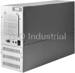
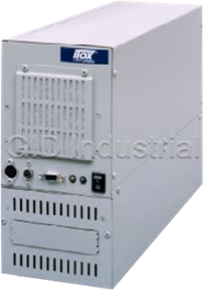
ITOX Tiger Cub PC platform for Computer Telephony and industrial applications
Part Number
Tiger Cub
Price
Request Quote
Manufacturer
ITOX
Lead Time
Request Quote
Category
Systems
Specifications
BIOS
General Software Embedded BIOS Ver.4 for AMD Élan
Board Size
13.1” (337 mm) x 3.9” (96 mm)
Cache
8 Kbyte unified, write-back
Disk Bays
3 disk drive bays, 3.5” (one externally accessible) All disks mount in removable drive tray.
Disk Controller
IDE controller: supports two drives up to 8GB each. Two sockets for Disk-on-Chip flash memory based disks.
Expansion Slots
3 full-length, full-height , 16 bit ISA. Hold down bracket provided with case
Fan
Motherboard/expansion slot area cooled by 8 cm fan with air filter, 14 CFM
Humidity
10% to 90% relative humidity , Non condensing
Input/Output
Ports Parallel printer port, EPP/EPC compatible. 2 serial ports, 16650 UAR T compatible. 4 line general purpose I/O, TTL level
Operating Temperature
0 to 45 C (32 to 113 F)
Options
DC input power supply
Power Supply
100 to 240 VAC switch selectable, 50/60 Hz 90 watts, with internal cooling fan and ATX connector
Processor
AMD Élan enhanced AM486 single chip Microcontroller. Available speeds – 33, 66 or 100 MHz (Factory configured)
RAM
4 Mbyte, 60 ns standard, 8 Mbyte available on special order
Real-Time Clock
Standard, with Sony CR2032 battery or equivalent
Size
15.5” (394 mm) x 5.25”(133mm) x 10.5”(266 mm)
Watchdog Timer
Standard
Weight
12.1 pounds(5.5 kgs) [not including disk drives]
Datasheet

Extracted Text
b
System
User’s Manual
Light Industrial Products...
http://www.itox.com
Tiger Cu
Copyright
This publication is provided for informational purposes only. The
any time, without obligation to notify any person or entity of such
revisions or changes.
Trademarks
®®
tion. IBM is a registered trademark of International Business Ma-
®
®
trademarks and registered trademarks of products appearing in this
Caution:
1
tions.
pose of used batteries according to the battery manufacturer’s instruc-
the same or equivalent type recommended by the manufacturer. Dis-
Danger of explosion if battery incorrectly replaced. Replace only with
manual are the properties of their respective holders.
is a registered trademark of Caldera. OtherDatalight, Inc.. DR-DOS
is a registered trademark ofM-systems Inc.. Datalight ROM-DOS
vanced Micro Devices, Inc. DiskOnChip is a registered trademark of
are registered trademarks of Ad- Élanchine Corporation. AMD and
is a registered trademark of Microsoft Corpora- MS-DOSMicrosoft
All Rights Reserved.
the right to revise this publication and make changes to its contents at
results of the use of this document. Further, the manufacturer reserves
ticular purpose. The user will assume the entire risk of the use or the
press or implied warranties of merchantability or fitness for any par-
the contents or use of this manual and specifically disclaims any ex-
manufacturer makes no representations or warranties with respect to
mission from the copyright holders.
to make any transformation/adaptation without the prior written per-
No part of it may be reproduced in any form or by any means or used
This publication contains information that is protected by copyright.
1
l
This equipment has been tested and found to comply with the lim-
its for a Class B digital device, pursuant to Part 15 of the FCC
rules. These limits are designed to provide reasonable protection
against harmful interference when the equipment is operated in a
residential installation. This equipment generates, uses and can ra-
diate radio frequency energy and, if not installed and used in ac-
cordance with the instruction manual, may cause harmful interfer-
ence to radio communications. However, there is no guarantee
that interference will not occur in a particular installation. If this
equipment does cause harmful interference to radio or television
reception, which can be determined by turning the equipment off
and on, the user is encouraged to try to correct the interference
by one or more of the following measures:
•Reorient or relocate the receiving antenna.
•Increase the separation between the equipment and the re-
•Connect the equipment into an outlet on a circuit different
from that to which the receiver is connected.
•Consult the dealer or an experienced radio TV technician for
.1The changes or modifications not expressly approved by the
party responsible for compliance could void the user's author-
ity to operate the equipment.
.2Shielded interface cables must be used in order to comply with
DFI-USA
8 Elkins Road135 Main Avenue
East Brunswick, NJ 08816Sacramento, CA 95838
(732) 390-2815(916) 568-1234
http://www.itox.comhttp://www.dfiusa.com
DFI Computers Ltd.
Unit 1, Kangley BusinessCentre100 Huan-Ho St.
Kangley Bridge RoadHsi-Chih Town28816 Stuhr
London, UK SE6 5AQ
(44-181)776-5555(886-2) 2694-2986(49-421) 565-6811
http://dfiuk.demon.co.ukhttp://dfiweb.comhttp://dfigermany@aol.com
2
GermanyTaipei Haien, Taiwan R.O.C.
Varreler Landstrabe 6
DFI GermanyDFI Inc.
U.S.A.U.S.A.
ITOX, Inc.
the emission limits.
Notice:
help.
ceiver.
FCC and DOC Statement on Class B
Tiger Cub User’s Manua
1
n
s
n
.
.
.
.
p
4
4
5
6
8
9
.
y
.
.
.
.
.
.
.
.
.
g
6
3
Running INTERSERV and INTERLNK................................... 3
Chapter 5 - File/Software Loadin
33Exit Without Changing CMOS.........................................
33Write To CMOS and Exit................................................
33Reset CMOS To Factory Defaults...................................
33Reset CMOS To Last Known Values.................................
32Standard Diagnosticc Routines.....................................
31Shadow Configuration..................................................
30Custom Configuration..................................................
26Standard CMOS Setup.................................................
26The Basic Input/Output System.....................................
Chapter 4 - General Software BIOS Setup Utilit
Booting DOS and Running MTEZ and INTERLNK.............
22
Chapter 3 - Power up Sequence
Back View ................................................................. 1
Front View ................................................................. 1
Wall Mounting the Tiger Cub........................................ 1
Installing Disk Drives..................................................... 1
Installing Expansion Cards............................................ 1
Removing the Access Cover........................................ 1
Chapter 2 - Hardware Installation and Setu
11
Package Checklist......................................................
10
System Configuration..................................................
8
Specfications.............................................................
8
Tiger Cub System Concept ........................................
Chapter 1 - Introductio
Table of Content
Introductio
t
.
.
.
.
.
.
.
s
.
.
.
.
.
g
4
y
8
2
3
.................................................................... 6Index
Year 2000 Statement................................................ 6
Appendix E - Year 2000 Compliance
Warranty Terms.......................................................... 5
Appendix D - Warrant
Frequently Asked Questions......................................... 5
Appendix C - Troubleshootin
50
Software Control of Watchdog Timer..........................
49
BOOT.COM...............................................................
49
ITOXSCR.COM...........................................................
49
ITOXLED.OBJ..............................................................
48
ITOXBLIN.COM...........................................................
Appendix B - Software Utilitie
45
System Board Connector Layout.................................
44
IRQ Assignements..................................................
43
J13 - General Purpose Input/Output Connector...........
43
J12 - Enable COM1 IRQ ......................................
42
J6, J8 - Watchdog Timer ............................
41
J5 - Local LED Indicators............................................
41
J1, J2 - DRQ/DACK Jumpers......................................
40
Connector/Jumper Setting Locations & Functions..
Appendix A - Board Layou
5
6
CHAPTER
1
7
Introduction
1
l
quently
supports reliable operation in unattended applications by restarting the
s
y
ITOX-EAR Motherboard
8
8 Kbyte unified, write-backCache
(Factory configured)
Available speeds – 33, 66 or 100 MHz
Microcontroller
AMD Élan enhanced AM486 single chipProcessor
be specified at the time of order.
motherboard. Consequentl, the processor speed and memory size must
The Tiger Cub’s processor and memory chips are soldered in place on the
Specification
system automatically if the software hangs-up.
programs onto the Tiger Cub’s hard disk. An on-board watchdog timer
during application development, diagnostic testing and for loading
One of the Tiger Cub serial ports can be used to control the Tiger Cub
is achieved by not providing these items.
disk in operational systems, and the most reliable, cost effective solution
, there is no need for a keyboard, mouse, video display or floppy
systems that utilize auto-executing DOS application programs. Conse-
mounted on a wall or placed on a shelf or table. It is designed for turnkey
environments. It is packaged in a small industrial enclosure that can be
The Tiger Cub is designed for unattended operation in light industrial
that require multiple, full length ISA interface cards.
low cost PC platform for Computer Telephony and industrial applications
The ITOX Tiger Cub uses state-of-the-art design to provide a compact,
Tiger Cub System Concept
Introduction
Features and Specifications
Tiger Cub User’s Manua
1
n
RAM
Standard
equivalent
each
based disks
Ports
R
Chassis Components
TX connectorA
Motherboard/expansion slot area cooled by
Disk Bays
.y
9
All disks mount in removable drive tra
externally accessible)
3 disk drive bays, 3.5” (one
8 cm fan with air filter, 14 CFM
Fan
90 watts, with internal cooling fan and
100 to 240 VAC switch selectable, 50/60 HzPower Supply
BIOS Ver.4 for AMD Élan
General Software EmbeddedBIOS
13.1” (337 mm) x 3.9” (96 mm)Board Size
4 line general purpose I/O, TTL level
2 serial ports, 16650 UAT compatible
Parallel printer port, EPP/EPC compatibleInput/Output
Hold down bracket provided with case
ISA3 full-length, full-height , 16 bit Expansion Slots
Two sockets for Disk-on-Chip flash memory
IDE controller: supports two drives up to 8GBDisk Controller
Standard, with Sony CR2032 battery orReal-Time Clock
Watchdog Timer
8 Mbyte available on special order
4 Mbyte, 60 ns standard,
Introductio
1
l
y
System Configuration
y
y
.y
10
include Microsoft MS DOS 6.22, IBM PC DOS 7.0, and Caldera DR-DOS.
system in the basic configuration. Optionally available operating systems
The Tiger Cub is supplied with the Datalight ROM-DOS 6.22 operating
drive controller card in one of the Tiger Cub’s ISA expansion slots.
floppy drive in the externally accessible drive bay and installing a floppy
tions requiring a floppy drive can be accommodated by installing a 3 ½”
Floppy drives are not typically used with the Tiger Cub. However, applica-
spare disk tra
to be performed by shipping the user a preloaded hard drive mounted in a
removable disk tray feature also allows field application software upgrades
drives are mounted in a removable disk tray for easy assembl. The
The flash disk chips mount in sockets provided on the motherboard. Hard
drive and one slave drive.
drive. The Tiger Cub’s internal IDE disk controller will support one primary
The Disk-on-Chip may be configured as the first (boot) drive or the last
and 3 ½” hard drives of various capacities.
configuration. Available options include 24 MB Disk-on-Chip Flash disk
Several disk storage options are available and are not included in the basic
available as factory installed options.
RAM memor. Higher speed processors and/or 8 MB of RAM are
The basic Tiger Cub is configured with a 33 MHz processor and 4 MB of
DC input power supplyOptions
10% to 90% relative humidit, Non condensingHumidity
0 to 45 C (32 to 113 F)Operating Temperature
15.5” (394 mm) x 5.25”(133mm) x 10.5”(266 mm)Size
12.1 pounds(5.5 kgs) [not including disk drives]Weight
Tiger Cub User’s Manua
1
n
Package Checklist
The Tiger Cub system package contains the following items:
•One Tiger Cub complete with motherboard and power supply
•
•One floppy disk with the following software
•One set of operating system software
•One Manual
Optional items such as disk drives may also be enclosed in the
package. Check your packing list carefully.
If any of these items are missing or damaged, please contact your
supplier for assistance.
11
• ITOXSCR.COM
• ITOXBLIN.COM
• BOOT.COM
• MTEZ terminal emulation software
One Power Cable
and Chapter 5 of this manual.
modem cable. The appropriate procedures are provided in Chapter 3
Cub to the serial port of a notebook computer or other device with a null
tion programs. This is accomplished by connecting COM1 of the Tiger
port (COM1) for loading software and local control/debugging of applica-
The Tiger Cub is designed to allow console redirection through the serial
Introductio
12
CHAPTER
2
and
Setup
13
Hardware Installation
2
l
opening the cabinet to prevent possible contact with the rotating fan
blade or hazardous voltage. The Tiger Cub is designed so that all high
voltage components remain enclosed in the lower portion of the cabinet
, contact with potentiallywhen the access panel is removed. However
hazardous voltage is possible if tools or screws enter the lower portion
of the case through the cable or cooling holes.
.ate postion based table below
Normal Input Voltage
Removing the Access Cover
r, disk drives, add-in boards, and other components.
workstation only. If such a station is not available, you
can provide some ESD protection by wearing an antistatic
wrist strap and attaching it to a metal part of the system
14
Perform the instruction procedures described at an ESD
processo
Electrostatic discharge (ESD) can damage yourWarning:
Installing Expansion Cards
installing expansion cards.
each end of the bracket and remove the bracket to provide access for
retaining bracket to hold expansion cards in place. Remove the screw at
expansion cards and set jumpers. The Tiger Cub is supplied with a
side & one on the other side) and remove the access cover to install
Remove the six screws on the side of the Tiger Cub cabinet (five on one
230200-240 Vac
115100-120 Vac
Switch Setting
AC Voltage Switch Settings
voltage selector switch on the rear panel of the Tiger Cub to the appropri-
with AC input voltage from 100 to 240 VAC at 50/60 Mz. Set the AC
The Tiger Cub is equipped with a dual range power supply for operation
Set Input Voltage Selector Switch
Always unplug the AC power cord from the Tiger Cub beforeCaution:
II. Hardware Installation and Set Up
Tiger Cub User’s Manua
2
p
chassis. If a wrist strap is unavailable, establish and maintain
contact with the system chassis throughout any procedures
requiring ESD protection.
supplied with the pads into the bracket so that they press on the pads at
V
15
slide the drive tray out the front of the unit.
the outside edges of the lower portion of the front panel. Then
Remove the two phillips head screws located closest tovoltage source.
erify that the Tiger Cub power cord is disconnected from the AC
It is not necessary to remove the access cover to install disk drives.
2. Remove the drive tray from the front panel of the Tiger Cub.
load all software required for the application at the same time.
Tiger Cub has a floppy drive). Most users will find it convenient to pre-
appropriate file loading utilities identified in Chapter 5 (not required if the
The hard drive must be loaded with the operating system including the
1. Pre-load your software onto the hard drive.
installed by ITOX.
installed in the unit. This procedure should be followed for disks not
as the Tiger Cub will be pre-loaded with the appropriate software and pre-
hard (and floppy) disk drives. Disks ordered from ITOX at the same time
The Tiger Cub uses a removable disk tray for quick and easy mounting of
Installing Disk Drives
the correct jumper setting for your system configuration.
should be replaced after the jumpers have been set. See appendix A for
an angle to hold the expansion cards firmly in place. The access cover
of the expansion card in the “V” groove of the pad. Install the screws
installed in the square holes in the bracket and positioned with the edge
installed. Then the black plastic pads supplied with the unit should be
The retaining bracket should be replaced after the cards have been
used to hold the filler plate in place.
the normal manner, and secure them in place with the screw previously
priate number of filler plates from the back of the unit, install the cards in
sion cards utilizing the 16 bit ISA interface standard. Remove the appro-
The Tiger Cub is designed to accept three full length, full height expan-
Hardware Installation and Setu
2
l
.y
Select the set of slots you want to use and mount the drive according to
type data cable through the opening so they can be connected to the disk
Wall Mounting the Tiger Cub
16
to slip over the heads of screws mounted in the wall or other vertical
narrow objects from entering the case. The mounting holes are designed
The Tiger Cub mountings have a protective back plate that prevents
wall is provided in the Tiger Cub box.
adequate support. A template for installing the mounting screws in the
of the front brackets and one of the rear brackets must be used to provide
recommended and will result in the most secure installation; at least one
Tiger Cub for wall mounting. Use of all four wall mounting points is
Four key-hole shaped mounting holes are provided in the side of the
surface, or wall mounted. Rubber feet are provided for table top operation.
The Tiger Cub is designed to be placed on a shelf, table or other flat
setup (see Chapter 4).
turer’s instructions) in the Basic CMOS Configuration section of the BIOS
applied to the unit. Enter the correct hard drive type (from disk manufac-
Complete any other hardware installation procedures before power is
6. Specify the correct hard disk type in the BIOS setup.
removed in step 2 above.
remain fully engaged. Secure the drive tray in place with the two screws
while doing this to keep them away from any sharp edges and insure they
Slide the drive tray back into the case; guide the cables into the opening
5. Install the drive tray back into the Tiger Cub case.
connectors are attached to the drive in the proper orientation.
drive. The connectors are keyed for proper attachment; make sure that the
where the drive tray mounts. Gently guide the power cable and ribbon-
Reach into the lower portion of the Tiger Cub case through the opening
4. Connect the data and power cables.
installing any of the drives if a floppy drive will be installed.before out
This position is typically reserved for floppy drives. Remove the knock-
out section that can be removed to provide exterior access to the drive.
the manufacturer’s instructions. The center drive position has a knock-
The drive tray includes slots for mounting up to three 3 ½ “ disk drives.
3. Install the drive(s) in the drive tra
Tiger Cub User’s Manua
2
p
17
the unit up and lifting the unit off the screw heads.
Cub down to secure it in place. It can be removed for servicing by sliding
Tiger Cub mounting holes over the screw heads and then slide the Tiger
Once the screws are installed in the wall to the proper depth, place the
to provide clearance for the thickness of the mounting bracket.
installed to allow a clearance of 1/16 inch (1.5 mm) under the screw head
mm) and a maximum head height of 0.2 inch (5 mm). The screws should be
screws with a head diameter between 0.35 inch (9 mm) and 0.55 inch (14
designed for ¼ inch (6 mm) pan head screws, but can be used with any
surface upon which the Tiger Cub is to be mounted. The holes are
Hardware Installation and Setu
2
l
Power LED
Console Redirection
(Green)
Switch
Power Switch
Green LED
Red LED
HD Active LED
18
(Yellow)
Yellow LED
Air Filter Access Screws
Connectors, Switches and Indicators
Front View of Tiger Cub System
Tiger Cub User’s Manua
2
p
COM1 Port
COM2 Port
AC Voltage
Selection Switch
Power Cord
Connector
19
(LPT1)
Parallel Port
Connectors, Switches and Ports
Back View of Tiger Cub System
Hardware Installation and Setu
20
CHAPTER
3
Power Up Sequence
21
3
l
Power Up Sequence
ITOXSCR.COM
BOOT.COM
When purchased with MS DOS or IBM PC-DOS program. With Datalight ROM-DOS program will
be REMDISK.EXE. With Caldera DR-DOS program will be FILELINK.EXE.
22
*
3) Turn on your notebook/PC.
cable will be inserted into the serial port of your notebook/PC.
the Tiger Cub system (see chapter 2 ). The other end of the
2) Plug one end of the null modem cable into the COM1 port on
1) Start with both the notebook PC & the Tiger Cub turned off.
enact the console redirection.
MTEZ must run on the notebook/PC from the floppy drive to
INTERLNK.EXE*
MTEZ
ITOXBLN.COM
programs:
The floppy disk provided with the system contains the following
provided rather than running a Windows DOS box.
We recommend that you boot DOS directly from the DOS disk
Tiger Cub.
enable the notebook to serve as the keyboard and display of the
The console redirection feature of the Tiger Cub will be used to
the Tiger Cub’s BIOS and loading software.
A notebook (or desktop) computer will be needed for setting up
Tiger Cub User’s Manua
3
e
cd MTEZ
A:\MTEZ>
A:\MTEZ>MTEZ (press enter)
Main Menu Screen
Dial ExpFax Redial Hangup File Change Shell Quit Terminal More
or 1st Letter to Select to Execute Esc to Exit Menu
Dial ExpFax Redial Hangup File Change Shell Quit Terminal More
Dial a Phone Number {Alt-D}
23
The MTEZ Menu box will appear once more.
position.ON Cub to the
5) Now turn the Power switch located on the front of the Tiger
or 1st Letter to Select to Execute Esc to Exit Menu
menu box (below).
to clear the MTEZESCAPE After seeing this screen select
Dial a Phone Number {Alt-D}
Alt-Z Help OffLine FDX CR MTEZ by WordPerfect Corp
The Main Menu screen will appear.
4) Boot DOS from the supplied disk and run MTEZ.
Power Up Sequenc
3
l
The keyboard and display of the notebook now act as the
Y
T
Use the following procedure to redirect the
keyboard and display back to the notebook PC.
abT
3)
24
to redirect the keyboard and display back to the Tiger Cub.
Type EXIT (return) and then press Escape
notebook.
The keyboard and display can now be used to control the
2) Select SHELL
The main MTEZ menu will reappear.
1) Press Alt +
drive to accomplish this task.
BOO.COM must be installed on the Tiger Cub’s hard
display are directed to Tiger Cub.
Type BOOT while in DOS when the keyboard and
If you need to reboot the Tiger Cub at any time:
programs.
ou may enter CMOS as described in chapter 4 or run your
keyboard and display of the Tiger Cub.
Now you have exited MTEZ and have control of the Tiger Cub.
again.ESCAPE6) Select
Tiger Cub User’s Manua
R
4
25
BIOS Setup Utility
CHAPTE
4
The Basic Input/Output System
of the basic level of communication between the processor and
peripherals. This chapter explains the Setup Utility for the General
After you power up your system and connect a console device as
described in chapter 3, the BIOS message appears on your screen
and you will see the memory count begin. After the memory test,
the following message will appear on the screen:
System Bios Setup - Utility v4.000
(C) 1996-7 General Software, Inc. All rights reserved
--------------------------------------------------------------------------
>Basic CMOS Configuration
Custom Configuration
Shadow Configuration
Standard Diagnostic Routines
Reset CMOS to last known values
Reset CMOS to factory defaults
Write to CMOS and Exit
Exit without changing CMOS
——--—————————————————————---——
...”
: Enabled
Primary Display : MONO/None Wait For F1 on Error
Typematic Keys : (Unused) NumLock State at Boot: Disabled
: (Unused)
Typematic Delay : (Unused) Memory Parity Check
Typematic Rate : (Unused) Exhaustive Memory Test: Disabled
Memory Test Tick : Enabled
Test Above 1 MB : Enabled
-----------------------------------------------------------------------------------------------
^E/^X/...”
SYSTEM CONFIGURATION BOX
SEEK HARD DRIVE AT BOO
SEEK FLOPPY AT BOO
the following:
ofall for standard defaultwill be the Enabled
is the default.MEMORY TEST TICK:
UnusedTYPEMATIC RATE :
UnusedTYPEMATIC DELAY :
UnusedTYPEMATIC KEYS :
Default
TYPEMTIC SECTION
Tiger Cub User’s Manual
4
Enable COM2 (Options: Enabled or Disabled)
This field specifies whether the second serial port connector on the
enabled.
COM2 Base Address (Options: 2F8 or 3F8)
This specifies the base address of the internal serial port on the
Tiger Cub. If set to (the default setting), there will be two se-
port connector will be disabled.
Enable LPT1 (Options: Enabled or Disabled)
This specifies whether the parallel port connector on the Tiger Cub
is enabled or disabled. The default setting is Enabled.
LPT1 Base Address (Options: 278 or 378)
This specifies the base address of the internal parallel port on the
Tiger Cub. The default setting is
Note: The DMA channels must be selected in the BIOS to match
the jumper setting used for J1 and J2. Refer to appendix A.
DMA0 Channel (Options: 0, 2, or 3)
Select this field to access the first DMA channel. The set-
ting is 2. Note that DMA channel two must be selected if a floppy
drive is installed.
DMA1 Channel (Options: 5, 6, or 7)
This specifies the second DMA channel which may be accessed.
The default setting is 6.
Shadow Configuration
Shadowing is the standard feature in which ROMs are copied to
31
faster RAM to improve system performance.
default
378.
rial ports, if set to 3F8, there will be one serial port and the first serial
2F8
Tiger Cub is enabled or disabled. The default setting is
BIOS Setup Utility
4
(C) 1996-7 General Software, Inc. All rights reserved
-------------------------------------------------------------------------------------------------
Shadowing :>Chipset Shadow 16KB ROM at C000 : Disabled
Shadow 16KB ROM at C400 : Disabled Shadow 16KB ROM at C800 : Disabled
Shadow 16KB ROM at CC00 : Disabled Shadow 16KB ROM at D000 : Disabled
Shadow 16KB ROM at D400 : Disabled Shadow 16KB ROM at D800 : Disabled
Shadow 16KB ROM at DC00 : Disabled Shadow 16KB ROM at E000 : Enabled
Shadow 16KB ROM at E400 : Enabled Shadow 16KB ROM at E800 : Enabled
Shadow 16KB ROM at EC00 : Enabled Shadow 64KB ROM at F000 : Enabled
-------------------------------------------------------------------------------------------------
^E/^X/
Frequently asked questions
How does Industrial Trading differ from its competitors?

Is there a warranty for the Tiger Cub?
Which carrier will Industrial Trading use to ship my parts?
Can I buy parts from Industrial Trading if I am outside the USA?
Which payment methods does Industrial Trading accept?
Why buy from GID?

Quality
We are industry veterans who take pride in our work

Protection
Avoid the dangers of risky trading in the gray market

Access
Our network of suppliers is ready and at your disposal

Savings
Maintain legacy systems to prevent costly downtime

Speed
Time is of the essence, and we are respectful of yours
Related Products
ITOX TIGER STAR industrial computer intended for light industrial applications
Request a Quote

The quote request has been received
Close

Facing challenges or have inquiries? Feel free to contact us!
Call Us +1-469-283-2440
What they say about us
FANTASTIC RESOURCE
One of our top priorities is maintaining our business with precision, and we are constantly looking for affiliates that can help us achieve our goal. With the aid of GID Industrial, our obsolete product management has never been more efficient. They have been a great resource to our company, and have quickly become a go-to supplier on our list!
Bucher Emhart Glass
EXCELLENT SERVICE
With our strict fundamentals and high expectations, we were surprised when we came across GID Industrial and their competitive pricing. When we approached them with our issue, they were incredibly confident in being able to provide us with a seamless solution at the best price for us. GID Industrial quickly understood our needs and provided us with excellent service, as well as fully tested product to ensure what we received would be the right fit for our company.
Fuji
HARD TO FIND A BETTER PROVIDER
Our company provides services to aid in the manufacture of technological products, such as semiconductors and flat panel displays, and often searching for distributors of obsolete product we require can waste time and money. Finding GID Industrial proved to be a great asset to our company, with cost effective solutions and superior knowledge on all of their materials, it’d be hard to find a better provider of obsolete or hard to find products.
Applied Materials
CONSISTENTLY DELIVERS QUALITY SOLUTIONS
Over the years, the equipment used in our company becomes discontinued, but they’re still of great use to us and our customers. Once these products are no longer available through the manufacturer, finding a reliable, quick supplier is a necessity, and luckily for us, GID Industrial has provided the most trustworthy, quality solutions to our obsolete component needs.
Nidec Vamco
TERRIFIC RESOURCE
This company has been a terrific help to us (I work for Trican Well Service) in sourcing the Micron Ram Memory we needed for our Siemens computers. Great service! And great pricing! I know when the product is shipping and when it will arrive, all the way through the ordering process.
Trican Well Service
GO TO SOURCE
When I can't find an obsolete part, I first call GID and they'll come up with my parts every time. Great customer service and follow up as well. Scott emails me from time to time to touch base and see if we're having trouble finding something.....which is often with our 25 yr old equipment.
ConAgra Foods