

 Manufacturers
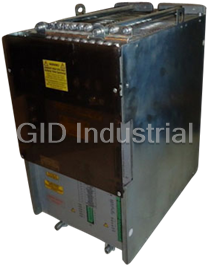
INDRAMAT KVR 1.3 30 3
Description
Indramat KVR 1.3 30 3 Supply Modules - KVR 1.3-30-3 Supply Module for Direct Mains Connection to 3 x AC 380...480 V
Part Number
KVR 1.3 30 3
Price
Request Quote
Manufacturer
INDRAMAT
Lead Time
Request Quote
Category
Systems
Specifications
Continuous bleeder power
Bleeder designed only for E-stops
Frequency
50 ... 60 Hz
Input Voltage
3 x 380 ... 480 (+ 10%)
Link circuit D.C. voltage
320 (+ 5%)
Link circuit peak power
90
Maximum regeneration energy
100
Peak bleeder power
40
Power dissipation inside control cabinet at maximum equipment load
170
Power dissipation outside control cabinet at maximum equipment load
480
Features
- Charging current limiting for bridge capacitors
- Controlled bridge voltage
- Direct mains connection
- Fuse protection is possible with circuit breakers
- High capacitance of the control voltage
- High overload capability
- Internal link circuit short-circuit
- It is possible to operate the drives for long periods even while braking
- Loss of heat due to energy in the control cabinet
- Power shutdown with the use of internal contactors
- Service friendly
- The drive systems reaction to a power failure can be programmed by adding an external link.
Datasheet

Extracted Text
engineering mannesmann Rexroth KVR 1.3-30-3 Supply Module for Direct Mains Connection to 3 x AC 380...480 V Application Manual DOK-POWER*-KVR*1.3****-ANW1-EN-P 266306 Indramat About this document Title KVR 1.3-30-3 Supply module for direct mains connection to 3x AC 380 to 480 V with mains regeneration Type of documentation Application Manual Documenttype DOK-POWER*-KVR*1.3****-ANW1-EN-E1,44 • 10.96 Internal file reference • Mappe 6 • KVR13-AN.pdf • 209-0049-4307-00 Purpose of documen- In this document you will find tation • the definition of the area of application • the electrical lay-out • the mechanical lay-out of the control cabinet • assembly and installation instructions • guidelines for selecting additional components • fault-finding tips Designation of documentation Release- Comments Change procedures up to present edition date 9.580.002.4-00/11.93 Nov./93 First Edition 209-0049-4307-00/08.95 Aug./95 Release DOK-POWER*-KVR*1.3****-ANW1-EN-E1,44 Okt./96 Introduction of document type Copyright © INDRAMAT GmbH, 1993 Copying this document, and giving it to others and the use or communication of the contents thereof without express authority, are forbidden. Offenders are liable for the payment of damages. All rights are reserved in the event of the grant of a patent or the registration of a utility model or design (DIN 34-1) The electronic documentation (E-doc) may be copied as often as needed if such are to be used by the consumer for the purpose intended. Validity All rights are reserved with respect to the contents of this documentation and the availability of the product. Published by INDRAMAT GmbH • Bgm.-Dr.-Nebel-Straße 2 • D-97816 Lohr Telephone 09352/40-0 • Tx 689421 • Fax 09352/40-4885 Dept. ENA (DE, FS) • DOK-POWER*-KVR*1.3****-ANW1-EN-E1,44 • 10.96 2 Table of contents Page Table of contents 1. Installing the INDRAMAT modular AC drive system 7 1.1. Main functions of supply module KVR 1 ..........................................8 2. Area of application 9 2.1. Power ratings .................................................................................10 2.2. Overload capabilities ......................................................................10 2.3. Data sheet for the KVR 1.3 ............................................................ 11 2.4. Conditions of use ...........................................................................12 2.5. Functional power features ..............................................................13 3. Electrical connections - installation guidelines 14 3.1. Terminal diagram............................................................................15 3.2. Mains connection - power section..................................................16 3.3. Fuse protection with direct mains connection ................................18 3.4. Mains supply earthing requirements ..............................................18 3.5. Commutation choke .......................................................................20 3.7. Link circuit choke............................................................................21 3.8. Link capacitor .................................................................................21 3.9. Additional capacitors at the link circuit ...........................................21 3.10. Electronics and fan supply .............................................................22 3.12. Bus connection for electronics supply and signal exchange .........23 3.11. Electronics buffer ...........................................................................23 3.13. Fault current protective device .......................................................25 3.14. Control cabinet check ....................................................................25 3.15. Mounting the KVR 1.3 in the control cabinet .................................26 3.16. Heat due to energy loss inside control cabinet ..............................29 3.17. Safety clearance inside control cabinet .........................................29 3.18. Front view of the KVR 1.3 with accessories ..................................30 4. KVR controller 32 • DOK-POWER*-KVR*1.3****-ANW1-EN-E1,44 • 10.96 3 Table of contents 4.1. Possible fault responses ................................................................32 4.2. Controlling the KVR with link circuit short-circuit ...........................34 4.3. Controlling the KVR 1 without link circuit short-circuit ...................36 4.4. Controlling the KVR to brake the drives under position control .....38 5. Description of interface 40 5.1. Link circuit short-circuit ..................................................................40 5.2. Power OFF .....................................................................................40 5.3. Power ON .......................................................................................40 5.4. Stopping the drives during an E-stop or mains fault ......................41 5.5. Signal voltages ...............................................................................42 5.6. "Ready" state .................................................................................42 5.7. Power feed working........................................................................44 5.8. Temperature pre-warning ...............................................................44 5.9. Mains relay energized ....................................................................45 5.10. Mains contactor dropped out .........................................................45 6. Fault-finding guidelines 46 6.1. Fault-finding ...................................................................................46 6.2. Safety guidelines ............................................................................46 6.3. Diagnostics display, fault list ..........................................................48 6.4. Fault list and remedies ...................................................................49 6.5. Equipment fuses ............................................................................54 7. Dimensional data 55 7.1. Dimensional data for KVR 1...........................................................55 7.2. Dimensional data for smoothing choke ..........................................56 7.3. Dimensional dat for commutatio choke ..........................................57 7.4. Dimensional data for link capacitor CZ 1.2-01-7 ............................58 7.5. Dimensional data for link capacitor CZ 1.02 ..................................58 7.6. Dimensional data for additional capacitor module TCM 2.1 (link capactior) ................................................................................59 • DOK-POWER*-KVR*1.3****-ANW1-EN-E1,44 • 10.96 4 Table of contents 8. Order information 60 8.1. Type codes KVR 1 .........................................................................60 8.2. Available versions - supply module KVR and accessories ............60 8.3. Summary of electrical connecting accessories ..............................61 8.4. Components list for mains supply with KVR 1 ...............................61 9. Index 62 • DOK-POWER*-KVR*1.3****-ANW1-EN-E1,44 • 10.96 5 • DOK-POWER*-KVR*1.3****-ANW1-EN-E1,44 • 10.96 6 1. Installing the Modular INDRAMAT AC Drive System 1. Installing the INDRAMAT modular AC drive system supply drive mains drive module supply module 3x AC 380 ... 460 V 50 ... 60 Hz programming module L1 L2 L3 signal regulate, voltages control, diagnose internal power contactor bleeder internal link circuit short-circuit n ist M 3 main drive motor KVRAufbau Figure 1.1: KVR 1 supply module as a part of the modular INDRAMAT AC drive system The INDRAMAT AC Drive System consists of a supply and the drive modules. Several drives can be mounted to a single supply module. Supply module KVR 1.3, with its regeneration capability, is a component of the INDRAMAT modular AC drive system. Supply module KVR 1 provides the link circuit d.c. voltage for the power supply and the control voltage for all connected INDRAMAT main and servo- drive modules. • DOK-POWER*-KVR*1.3****-ANW1-EN-E1,44 • 10.96 7 1. Installing the Modular INDRAMAT AC Drive System 1.1. Main functions of supply module KVR 1 The power rectifier of the KVR rectifies the threephase mains alternating Power supply of the voltage and provides a regulated link circuit d.c. voltage for the drives power drives supply. The KVR 1 operates as an inverter in the event the drives are generator-driven, and feeds the power back into the mains. Buffer capacitors provide sufficient smoothing. In the event of a power failure, or, if the power supply should be switched off, then the energy regenerated as a result of the braking of the motors will be assimilated by the bleeder resistor in the KVR 1. The KVR1’s internal power contactor makes it possible to isolate the drives from the mains. The KVR supplies the drive module’s electronics via the signal voltage bus. In Supply to the the event of a mains failure, the signal voltages will receive power from the electronics d.c. link circuit. As a result, the drive electronics remain operational when the drives are in generator mode. The KVR has been equipped with extensive monitoring functions. These Drive monitoring communicate with the drive modules via the signal voltage bus. system The Bb1 contact of the KVR is very important for the drive system operation. The power supply can be connected only when Bb1 contact is closed. link circuit bleeder short-circuit 1U1 320 V DC DC to supply the 1V1 drives with DC 1W1 power K1 2U1 ~ drive supply 2V1 and monitor = 2W1 drive ready & Bb1 FPAufbauKVR power ready Figure 1.2: The KVR 1.3 supply module as part of the Indramat AC drive system • DOK-POWER*-KVR*1.3****-ANW1-EN-E1,44 • 10.96 8 2. Area of Application 2. Area of application It is possible to operate the Indramat drives supply modules of the KVR series at a continuous mechanical rate of 24 kW. The KVR feeds the regenerated energy created by the braking of the motors back into the mains. The continuous regeneration power can equal 20 kW. The KVR is thus particularly well-suited for those applications where high continuous regen- eration power is required. Supply module KDV2, with built-in 2kW bleeder resistor, is available for smaller continuous regeneration requirements. L1 mains L2 L3 feed and regen. power supply module 30 kW drive module 20 kW P P m m continous mechanical rate of up to 24 Kw KVRLeistbereich Figure 2.1: Power range for supply module KVR 1.3 • DOK-POWER*-KVR*1.3****-ANW1-EN-E1,44 • 10.96 9 2. Area of application 2.1. Power ratings The effective performance of the KVR 1 can be adapted to the demands of the respective application by using additional components. (1) (2) (3) (4) (5) (6) Supply module KVR 1.3-30-3 additional components P P P P W P smoothing commutation link bridge DC KB-3 KB-03 BM max m kW kW kW kW kWs kW choke choke capacitor capacitor in- regen. in- regen. in- regen. coming coming coming 15 10 30 20 45 25 40 100 12 GLD 17 KD 23 – – – – – – 25 16 50 32 75 37 40 100 20 GLD 18 KD 24 – – – CZ 1.2-01-7 or TCM 2.1-01-7 30 20 60 40 90 50 40 100 24 GLD 19 KD 25 CZ 1.02 TCM 2.1-02-7 (1) P = link circuit continuous power (4) P = peak bleeder power DC BM (2) P = link circuit short-term power (5) W = maximum regen. energy KB-3 max 3 s (accel/decel of main drives) (3) P = link circuit peak power for (6) P = mechanical power for KB-03 m 0.3 s (accel/decel of servo drives) ON time > 10 s Figure 2.2: Power range of the KVR 1.3 2.2. Overload capabilities It is possible to overload the KVR for a short period in order to accelerate feed and main drives. The highest possible acceleration rate must be taken into consideration in the projection and may not be exceeded. 300 peak power for 0.3 seconds to accelerate the feed drive 200 power limits short-term operating power for 3 seconds to accelerate the main drive 100 continuous rating for operating periods longer than ten seconds 10 TVDBelastungsdiagr 0,3 3 ON time t/s Figure 2.3: Load diagram - KVR 1 • DOK-POWER*-KVR*1.3****-ANW1-EN-E1,44 • 10.96 10 load P/% 2. Area of application 2.3. Data sheet for the KVR 1.3 Description Symbol Unit KVR 1.3-30-3 Power supply Input Voltage U(ACN) (V) 3 x 380 ... 480 (+ 10%) Frequency f(N) (Hz) 50 ... 60 Hz Link circuit D.C. voltage U(DC) (V) 320 (+ 5%) Continuous link circuit power P(DC) (kW) 30/20 (with links and link circuit (feed and regeneration) capacitors of 2 mF) Link circuit peak power P(KB-03) (kW) 90 Peak bleeder power P(BM) (kW) 40 Continuous bleeder power P(BD) (kW) Bleeder designed only for E-stops Maximum regeneration energy W(max) (kWs) 100 with power off Power dissipation inside control P(V) (W) 170 cabinet at maximum equipment load Power dissipation outside control P(V) (W) 480 cabinet at maximum equipment load KVR 1.3 weight m (kg) 31 Weight of mechanical accessories m (kg) 1.7 Weight of LE 4 fan m (kg) 4.2 Electronics supply Input voltage U(AC) (V) 3 x 380 ... 460 (+10%) Frequency f(N) (Hz) 50 ... 60 Power consumption at maximum load S(el) (VA) 500 Fan supply Input Voltage U(AC) (V) 230 (+6/-10%) or 115 (+ 10%) Frequency f(N) (Hz) 50...60 Maximum power consumption S(L) (VA) 70 (per heatsink ventilator) Control voltage output +24 V Load voltage U(L) (V) 22 ... 26 (ripple 2%) +24 V Continuous current I(UL) (A) 11 ±15 V Measuring voltage U(M) (V) 14.9 ... 15.1 (ripple 0.1%) +15 V Continuous current I(+UM) (A) 2.0 -15 V Continuous current I(-UM) (A) 2.0 Environmental Conditions o Permissible ambient temperature T(amb) ( C) +5 ... +45 at rated data o Maximum ambient temperature T(m.amb) ( C) +55 at reduced data o Storage & transportation temperatures T(L) ( C) -30 ... +85 Installation altitude without derating maximum 1000 meters above sea level Permissible relative humidity maximum 95% 3 Permissible absolute humidity 25g water/m air Degree of contamination non-conductive dirt/no condensate Protection category IP 10 as per DIN 40 050 Figure 2.4: Data sheet - KVR 1.3 • DOK-POWER*-KVR*1.3****-ANW1-EN-E1,44 • 10.96 11 2. Area of application 2.4. Conditions of use Increased ambient The ratings and control voltages listed in the data sheet for the KVR 1 are valid temperatures with ambient temperatures of +5° to +45° C. The maximum permissible ambient temperature is +55 °C. The output data thus drops as depicted in the following diagram. temperature factor [%] 100 80 60 40 Umgebtemp 20 0 0 10 20 30 40 50 60 ambient temperature ϑ [°C] Figure 2.5: Drop in power data with increased ambient temperatures. Installation elevation The KVR 1.3’s output power data drop in accordance with the following exceeds 1000 meters diagram when installation altitude is above 1000 meters. reduction factor [%] 100 80 60 40 HöhenRed 20 0 0 1000 2000 3000 4000 5000 installation altitude [m] Figure 2.6: Drop in data with installation altitude above 1000 meters • DOK-POWER*-KVR*1.3****-ANW1-EN-E1,44 • 10.96 12 2. Area of application 2.5. Functional power features • It is possible to operate the drives for long periods even while braking The energy created by braking the motor is fed back into the mains with little loss of power. • Direct mains connection The KVR can be directly connected to 3 x AC 380...480V, 50...60 Hz mains without the use of a transformer. • Power shutdown with the use of internal contactors The contactor which shuts down the drive’s power supply is a component of the KVR1. • Internal link circuit short-circuit Internal link circuit short-circuits have the ability to brake synchronous motors in the event of a problem in the electronics of the motor. • High overload capability Peak power of 90 kW to accelerate motors. • Loss of heat due to energy in the control cabinet The heatsink is located outside the control cabinet. This makes compact control cabinets possible. • Fuse protection is possible with circuit breakers – Expensive semi-conductor fuses are not needed. – No special fuses for exports. • The drive systems reaction to a power failure can be programmed by adding an external link. – Without the links, the motors brake at maximum torque. – With the links, there is a signal to the NC control via a voltageless contact. Thus, the shutdown of the motors can be guided by the NC. Expensive tools or workpieces are protected against damage. • Controlled bridge voltage No reduction in drive response in the event of mains undervoltage. • Charging current limiting for bridge capacitors The inrush current can be ignored when selecting the switchgear for the power supply. The service life of the switchgear is increased. • High capacitance of the control voltage It is possible to connect ten drive modules to one supply module. • Service friendly – Signal lines are connected with screw terminals. – A numeric display makes extensive diagnostics and controlled elimination of faults possible. • DOK-POWER*-KVR*1.3****-ANW1-EN-E1,44 • 10.96 13 3. Electrical Connections – Installation Guidelines 3. Electrical connections - installation guidelines The KVR 1.3 installation plan found in this document is a recom- mended guideline of the equipment manufacturer. The wiring diagram of the machine manufacturer should be used for installation. • DOK-POWER*-KVR*1.3****-ANW1-EN-E1,44 • 10.96 14 3. Electrical Connections – Installation Guidelines 3.1. Terminal diagram APKVR1 Figure 3.1: Connection plan - supply module KVR 1 • DOK-POWER*-KVR*1.3****-ANW1-EN-E1,44 • 10.96 15 Connection diagram for supply module KVR 1 with direct mains connection for power and electronics components - internal power switching PE central grounding point 3xAC (380 - 460) V L3 for each drive module (50 - 60) Hz L2 L1 Q1 U1 V1 W1 L1 - link circuit L1 C3 C2 smoothing choke L2 - commutation choke L2 F2 Note phase C2 - link circuit capacitor coincidence! (for link circuit U2 V2 W2 1 2 PN - + continous power>25kW) C3 - bridge capacitor (for link circuit continuous power>15 kW) X 2 1 X 7 ZKS X 12 PE 2 BR1 ZKS ZKS 3 OFF 4 OFF OFF 5 L- DC 300V ON 6 ON ON busbars K1 L+ X 3 X 9 1 power NC-controlled 2 NCB supply braking 3 +15VM 4 1 0VM max. 100 mA UD 5 2 -15VM BB electronic Supply 6 3, 4 electronics +15V supply, for 7 5, 6, 7, 8 +24V supply 0VM signal servo- max. 2 A 8 9, 10 0VL exchange, drives -15V 11, 12 X 5 16-pin and/or +24V 13, 14 1 bus main 0VL 15 connection spindle 2 K1 acknowledge power on UESS 16 motors 3 shield X1 K1 4 KVR 1.3 acknowledge power off 5 Supply module with direct mains connection 6 K1 X14a - with mains power regeneration X 4 1 L1 - with regulated link circuit supply for ready 2 BB1 additional - with integrated heat exchanger 3 equipment N power voltage fans UD 4 in order 5 TVW temperature pre-warning 6 X14b X13 F6 external L1 L1 AC 220V or heatsink M 115V depending fan N N on type of ventilation 2U1 2V1 2W1 RB1 RB2 EB IB EPU+ EPU - 1U1 1V1 1W1 1L+ 2L+ P N 3. Electrical Connections – Installation Guidelines 3.2. Mains connection - power section The KVR can be connected to threephase networks with 3 x AC 380...480V, Direct mains 50...60 Hz without the use of a transformer. connection Supply module KVR 1, with its ability to regulate current, offers the lowest possible mains power without reactive current load. Current regulators in switched-mode power supplies cause mains system perturbation, the level of which does not depend on known system conditions (short-circuit power, mains inductance) at the installation site of the machine. The KVR is basically operated with a commutation choke to eliminate mains reactions. If the link circuit continuous rating is greater than 15 kW, an additional link capacitor is required (see 3.8). 3 x AC 380 … 480 V L1 L2 L3 PE mains fuse NC-control unit U1 V1 W1 NC 2 10 mm 2 2 ≥10 mm U2 V2 W2 1 2 2 ≥10 mm X7 PE busbar 1U1 1V1 1W1 1L+ 2L+ RB1 RB2 P X7 2U1 2V1 2W1 EPU+ EPU- IB EB N connecting block drive drive drive KVR module module module 1 twisted main conductor; max. length of 10 m; line cross section as per EN 60 204 (VDE 0113) 2 2 cross section as with main conductor but a min. 10 mm KVRNetzanschluß Figure 3.2: Mains connection power component KVR Cross-section of the power supply line, and recommended fuses, see section 3.3. Each drive module must be separately connected with a ground wire to the PE busbar of the KVR. The leakage current coming over the PE conductor exceeds 3.5 mA AC. As a result, the KVR 1.3 requires a permanent connection. Also see section 3.13. • DOK-POWER*-KVR*1.3****-ANW1-EN-E1,44 • 10.96 16 3. Electrical Connections – Installation Guidelines Mains connection via a If the mains voltage is less than 3 x AC 380 V or greater than 3 x AC 460V, then transformer a transformer can be used to adapt the mains voltage. The mains inductance (stray inductance) of transformers can vary consider- ably dependent upon power and type. For this reason, a commutation choke will be necessary even when a transformer is used. Required transformer power: SP = x 3xU/. 25 5 TR DC N S = transformer power in VA Tr P = continuous link circuit power in W DC U = transformer output voltage in V N L1 L2 L3 PE mains fuse Anpaßtransformator matching transformer commutation choke X7 PE-busbar KVR 1U1 1V1 1W1 1L+ 2L+ RB1 RB2 P X7 N 2U1 2V1 2W1 EPU+ EPU- IB EB connecting block KVR Kommdross Figure 3.3: Mains connection of the KVR via a transformer • DOK-POWER*-KVR*1.3****-ANW1-EN-E1,44 • 10.96 17 3. Electrical Connections – Installation Guidelines 3.3. Fuse protection with direct mains connection The mains connection for KVR 1’s power component with direct mains connection can be secured with the use of gL-type circuit breakers or fuses. The fuse rating must not exceed 63 A. The following recommendations apply to fuses with circuit breakers for direct mains connections. If fuses are used, then fuses of the type gL may be used. Semi-conductor fuses are not required. The fuses selected must correspond to the mains current. P DC I = N Ux25.5 N I = mains current in A N P = continuous link circuit rating in W DC U = mains voltage in V N link circuit connected load mains current power circuit set cross section power at 380V at breakers current of mains 3) 380V 480V Siemens type line 1) 2 15 kW 20 kVA 30 A 27 A 3VU1600-.MP00 30 A 6 mm 2) 2 25 kW 33 kVA 50 A 45 A 3VF1231-1FH41-.... 50 A 16 mm 2 2 30 kW 40 kVA 60 A 54 A 3VF1231-1FK41-.... ) 63 A 16 mm 1) Maximum back-up fuse (gL) as per manufacturer: 200A NH with voltages up to 500 V 2) Maximum back-up fuse (gL) as per manufacturer: 160A NH 3) Line cross section as per EN60204 - B1 installation type - correction factors not considered Figure 3.4: Recommended fusing of the KVR 1.3 3.4. Mains supply earthing requirements The KVR can be connected to earthed, threephase mains supplies without the Grounded threephase need for potential isolation. mains On non-earthed threephase mains supplies (IT mains), the phase-to-phase Ungrounded voltage is present during an earth fault between the case and the power threephase mains connection of the KVR. The KVR 1 can be protected against overvoltages if • the KVR 1.3 is connected via a transformer, and • if the machine is protected by overvoltage conductors. Connecting the KVR 1.3 via an isolation transformer offers the best protection against overvoltage and the greatest degree of operating safety. • DOK-POWER*-KVR*1.3****-ANW1-EN-E1,44 • 10.96 18 3. Electrical Connections – Installation Guidelines • Periodic overvoltages at the KVR 1.3 between the phase conductor (1U1, Overvoltages 1V1, 1W1, 2U1, 2V1, 2W1) and the housing should not be permitted to exceed 1000V (peak value). • Non-periodic overvoltages, as per VDE 0160, between the phase conductor and the housing are permissible for the KVR 1.3 in terms of the following diagram. U +ΔU N U N 3 2.6 2.4 2.3 2.2 2 T 1.8 1.6 1.4 1.2 1.15 1.1 DGUespg 1 0.1 0.2 0.4 0.6 1 1.3 2 4 6 10 20 T (ms) Figure 3.5: Permissible non-periodic overvoltages as per VDE 0160 The KVR 1.3 can be connected to 3 x 480V. The maximum permissible overvoltage is thus: 480 V x √2 x 2.3 = 1560 V • DOK-POWER*-KVR*1.3****-ANW1-EN-E1,44 • 10.96 19 ΔU U N ΔU 2 3. Electrical Connections – Installation Guidelines 3.5. Commutation choke A commutation choke is used to operate the KVR to eliminate mains reactions. (For connections and wiring diagrams see sections 3.3. and 3.2., for power loss, see section 7). The size of the commutation choke is determined by the continous link circuit power required for the drives. Continous link circuit power Commutation choke up to 15 kW KD 23 up to 25 kW KD 24 up to 30 kW KD 25 Use the busbars found in the connection accessories of the drive module to connect the drive modules to the d.c. voltage link circuit. Use twisted single core leads with longer connections (maximum one meter length). L1-link circuit choke C3-bridge capacitor Zwischenkreisdrossel 2 16 mm with GLD 17 Brückenkapazität 2 2 25 mm with GLD 18 Zwischenkreiskapazität 6 mm with CZ 1.2-01-7 2 2 35 mm with GLD 19 Leitungsquerschnitte 10 mm with TCM 2.1-02-7 max. 1 m twisted max. 1 m twisted P 1L+ 1L- N max. 1 m L- L- L- twisted 2 16 mm L+ L+ L+ C2-link circuit drive drive capacity KVR module module Cross-section is dependent on the link circuit continuous rating to be transmitted, 2, at least 16 mm max. 1 m twisted L- 2 P in kW A in mm DC L+ 19 16 24 25 drive module mains cross section as per EN 60204 - installation type B1 - corrective factors not considered KVRZwkreis Figure 3.6: Wiring the DC voltage link circuit • DOK-POWER*-KVR*1.3****-ANW1-EN-E1,44 • 10.96 20 3. Electrical Connections – Installation Guidelines 3.7. Link circuit choke The KVR 1 must always be operated with a link circuit choke in the "L+"-line. (For length of line and wiring lay-out, see 3.6; power loss, see section 7). Continuous link continous power Link circuit choke up to 15 kW GLD 17 up to 25 kW GLD 18 up to 30 kW GLD 19 3.8. Link capacitor When link circuit power is greater than 15 kW, the KVR is operated with an additional link capacitor to eliminate mains noise. The voltage at P and N of the KVR can equal up to 715 V. (Line length and wiring lay-out see 3.6.) Continous link circuit power Link capacitor 15 kW —— 25 kW CZ 1.2-01-7 30 kW TCM 2.1-02-7 3.9. Additional capacitors at the link circuit To increase the KVR1’s performance, additional capacitor CZ 1.02, or additional capacitance module TCM 1.1, may be connected to the d.c. link circuit. (Mains length and wiring lay-out, see 3.6.) Continous link circuit power Additional capacitor up to 25 kW —— up to 30 kW CZ 1.02 In a few applications the drives have to retract following a mains failure or an E-stop. The energy stored in the link circuit can be used for this. The stored link circuit energy can be increased by further additional capacitors. Maximum additional capacitor: C = 18 mF (e.g., 22 x TCM 1.1-08.WO). max • DOK-POWER*-KVR*1.3****-ANW1-EN-E1,44 • 10.96 21 3. Electrical Connections – Installation Guidelines 3.10. Electronics and fan supply Electronics supply Connection voltage: 3 x AC 380...480V, 50...60 Hz Connecting power: 500 VA (with electronics running at maximum). It is necessary for the mains connections for power and electronics to be in phase for the KVR to be able to feed back into the mains. The mains connection line for the electronics only requires a short-circuit switch. Commercial circuit breakers may be used, e.g., heavy-duty switch 3VU 1300-OMKOO-4...6 A (made by Siemens). Maximum back up fuse equals 10 A. L1 L2 L3 Q1 F2 L2 X7 1U1 1V1 1W1 2U1 2V12W1 KVR X13 fan supply Lüfterversorg Figure 3.7: KVR mains connection of the electronics and fan supply Fan supply All external heatsinks are connected to plug X13/KVR. Connection power: 70 VA per heatsink fan Connecting voltage: fan unit LE4-220 AC 220/230 V 50/60 Hz fan unit LE4-115 AC 110/115 V 50/60 Hz • DOK-POWER*-KVR*1.3****-ANW1-EN-E1,44 • 10.96 22 3. Electrical Connections – Installation Guidelines 3.11. Electronics buffer Terminal box X7/EPU+EPU-. 2. Connection cross-section equals 1 mm An additional capacitor may be necessary if the drives are to be shutdown position controlled in the event of a power failure. Ouptut UD reports a power failure.The NC control must then initiate a position controlled shutdown of the drives within 10 ms for the drive electronics to remain functional. If it takes the drives more than 10 ms to feed energy back into the link circuit, then additional capacitors should be used to maintain power supply to the electronics. An aluminum electrolytic capacitor is recommended due to lack of space. The voltage between EPU+ and EPU- can reach DC 450V. The capacitor must be able to handle this voltage. To avoid damage, rate the KVR for a maximum of 680 μF. Buffer capacitor Buffer time (with maximum electronics load) 20 ms 150 μF 50 ms 270 μF 100 ms 680 μF 3.12. Bus connection for electronics supply and signal exchange Bus connection X1 has two functions: – voltage supply to drive electronics – exchange of signals between supply and drive module(s) The bus connection line is part of the electrical accessories of the drive module. (1) (2) bus connection plug X1 plug X1 UD UD 1 1 BB BB 2 2 +15V +15V 3 3 +15V 0VM 4 4 0VM 0VM 5 5 0VM 0VM 6 6 0VM 0VM 7 7 0VM -15V 8 8 -15V -15V 9 9 0VL -15V 10 10 +24V +24V 11 11 +24V 12 12 0VL 13 0VL 14 free 15 (1) plug X1 with 12 pin type equipment 16 (2) plug X1 with 16 pin type equipment Bus12_16.fh3 Figure 3.8: Bus connection transition from 12-pin to 16-pin bus plugs • DOK-POWER*-KVR*1.3****-ANW1-EN-E1,44 • 10.96 23 3. Electrical Connections – Installation Guidelines For checking the correct plug connection, the bus connection is terminated with an end plug. The KVR’s power cannot be switched on without the end plug. The KVR can also be located in the center of the drive package. In that case, only one end of the bus connection requires the terminal plug. The terminal plug is a part of the KVR’s electrical accessories. 2 3 2 3 10 11 12 pin end plug 16 pin end plug Endstecker Figure 3.9: End plug to terminate bus connection • DOK-POWER*-KVR*1.3****-ANW1-EN-E1,44 • 10.96 24 3. Electrical Connections – Installation Guidelines 3.13. Fault current protective device It is recommended that the overcurrent fuse (fuse, power circuit breaker) switch the machine off if there is a short in the housing. If an FI current limiting type circuit breaker is absolutely required in TT-mains because of the extent of the grounding resistance, then the following must be noted. The capacitive leakage currents in switch-mode drives generally flow to earth. The extent of the leakage current depends on • the number of drives used • the length of the motor power cable • the grounding conditions at the installation site The leakage current is inevitably increased, if steps are taken to improve the electromagnetic compatibility (EMC) of the machine (mains filter, shielded lines). This means that FI current limiting type circuit breakers with nominal fault currents equal to less than 0.3 A should generally not be used! False tripping can occur when inductances and capcitances are switched on (interference suppression filters, transformers, contactors, magnetic valves). Commercially available pulse current sensitive FI current limiting ~ _∩_∩ _ type circuit breakers (machine identification ) do not guarantee the protection of electronic devices with threephase link circuits (B6 circuit). The protection of electrical apparatus mounted to a pulse current sensitive FI current limiting type circuit breaker together with devices which have a B6 circuit, can be affected. Use either FI current limiting type circuit breakers which switch off with d.c. fault currents, or mount an isolation transformer into the mains supply line. If isolation transformers are used, then these should tune the overcurrent protective device to the impedance of the fault loop so that there is a powering down given a fault. Connect the star point of the secondary winding with the protective conductor of the machine. 3.14. Control cabinet check No voltages other than those specified in the data sheet or in the interface notes must be connected. All KVR1 connections must be isolated prior to high-voltage testing of the control cabinet. • DOK-POWER*-KVR*1.3****-ANW1-EN-E1,44 • 10.96 25 3. Electrical Connections – Installation Guidelines 3.15. Mounting the KVR 1.3 in the control cabinet The heatsink of the KVR.3 is located on the back of the unit. It should be mounted so that the heatsink protrudes out of the back of the control cabinet. The greatest amount of heat (approximately 80%) is lost outside of the control cabinet, therefore, compact control cabinets may be used. This either com- pletely eliminates or reduces any additional costs for control cabinet air conditioning. P Vext P Vint air shaft power loss Q = 36 l/s P = 50 Pa max V = 3...4 m/s air KD... heatsink fan motor heatsink fan housing or cabinet completely sealed air current Kühlart Figure 3.10: Mounting the KVR in the control cabinet and distributing heat loss A shaft is needed for the air used in the cooling process. The air shaft and the Cooling with heatsink are supplied as part of the fan unit LE 4- ... . INDRAMAT's heatsink In the event that several heatsinks are cooled by a shared fan in a shared air Cooling with a central shaft, then there must be enough cool air. To be certain, check air stream Q. fan • DOK-POWER*-KVR*1.3****-ANW1-EN-E1,44 • 10.96 26 internal external 3. Electrical Connections – Installation Guidelines Fingerschutz forcierte Kühlung Figure 3.11: Mounting the KVR in the control cabinet • DOK-POWER*-KVR*1.3****-ANW1-EN-E1,44 • 10.96 27 K V R thread M8 air shaft (1) 69 space for heatsink filister head cap screw 8xM4x16 Note direct connection between (2) contact disc M8/4x back wall of control cabinet and mounting frame! KD module assembly frame (2) hexagon socket safety guard (1) with SW5 fan mounting frame (1) thread M4 space for additional KD modules space for additional fans back wall of housing space for fan Parts labelled wth (1) are part of fan for forced cooling (1) filister head cap screw fan unit LE 4- ... . 2xM4x14 (1) Parts labelled with (2) are part of mounting kit M1 - KD. KVRMont filister head cap screw 4xM4x (1) 185 3. Electrical Connections – Installation Guidelines Figure 3.12: Spaces and dimensions within the control cabinet • DOK-POWER*-KVR*1.3****-ANW1-EN-E1,44 • 10.96 28 Drill diagram for KVR 1 supply module Spacing dimensions in the control cabinet 110 ±0.5 110 ±0.5 155 ±0.5 110 ±0.5 155 ±0.5 110 ±0.5 spacing dimension spacing dimension 110 ±0.5 KDS KDA 3 KVR 1 KDA 3 KDS KVR 1 4xø11 96 ±0.2 96 ±0.2 KDF KDF 8xø5 == == 86 +1 110 ±0.5 110 ±0.5 92 ±0.5 92 ±0.5 110 ±0.5 110 ±0.5 KVR 1 KDS TDM TDM KDS KVR 1 space for KDF 3/4 3/4 KDF heatsink 110 ±0.5 110 ±0.5 137 ±0.5 92 ±0.5 155 ±0.5 110 ±0.5 KDA 3 TDM TDM KDA 3 18 KVR 1 KVR 1 3/4 3/4 looking from front towards mounting area == 6xø5 78 ±0.2 92 18Teilung 133 ±0.2 115 9 50+1 351 +1 11 373 ±0.2 15 403 ±0.2 555 40 90 3. Electrical Connections – Installation Guidelines 3.16. Heat due to energy loss inside control cabinet The heat loss of the KVR is dependent upon the continuous output of the link circuit. The greatest loss of heat occurs outside the control cabinet. The heat loss inside the control cabinet is depicted in the following diagram. link circuit continuous power in kW 30 20 10 600 300 200 50 100 150 total loss in W loss in control cabinet in W Verlust Figure 3.13: Heat from energy loss is dependent on the continuous link circuit power 3.17. Safety clearance inside control cabinet The bleeder resistor is arranged in a separate housing within the KVR 1. Flammable materials such as conductors and cable channels must have a minimum clearance of 300 mm upwards, and 40 mm to the side and in front of the housing. bleeder housing Skizze3D Figure 3.14: Safety clearance inside the control cabinet • DOK-POWER*-KVR*1.3****-ANW1-EN-E1,44 • 10.96 29 40 80 100 3. Electrical Connections – Installation Guidelines 3.18. Front view of the KVR 1.3 with accessories Endstecker KVR supply module grounding busbar mains connection for link circuit choke supply 1U1 1V1 1W1 1L+ 2L+ RB1 RB2 P N connection for bridge capacitor EPU- IB EB 2U1 2V1 2W1 EPU+ LED +24V/±15V/+5V X7 diagnostics display L- output for link circuit voltage L+ 00 terminal plug for X9 01 attachment 02 definition to the drive module 03 installed 04 of furthest away 05 X1 06 diagnostics SN240060-02029 A01 07 AC SERVO POWER SUPPLY RESET S2 08 displays 09 10 11 12 plug-in terminals 13 X2 to connect signal lines X3 X4 X5 drive module fan supply heatsink connection FAKVR fan supply Figure 3.15: Front view of KVR with connecting accessories • DOK-POWER*-KVR*1.3****-ANW1-EN-E1,44 • 10.96 30 • DOK-POWER*-KVR*1.3****-ANW1-EN-E1,44 • 10.96 31 4. KVR controller 4. KVR controller The control signals of the mains contactor and the link circuit short circuit in the KVR that are suggested by INDRAMAT illustrate the operating principle. Other controller configurations are outlined in this chapter. The choice of control and its effect depends upon the range of functions and the sequence of actions of the whole plant and is the responsibility of the equipment manufacturer. 4.1. Possible fault responses A: shutdown due to Stopping the drives with or without link circuit short-circuit fault in drive In the event of a malfunction in the drive electronics, the link circuit voltage electronics is shorted as an additional safety measure to brake the drives to a standstill. With link circuit short-circuits, synchronous motors are always braked to standstill (MAC or MDD) whether or not the drive electronics are still operational. Asynchronous motors (2AD or 1MB) are not braked if link circuit voltage is short-circuited. Without link circuit short-circuit, functioning drives are braked at maximum torque. It must, however, be assumed that there will be a slowing down without electrical braking in those drives where the control electronics are disrupted or those where regeneration lines are interrupted. The link circuit short-circuit can only then be obviated, if slowing down without braking will not result in damage. As an alternative, it is possible to use motors with mechanical blocking brakes. How to best shutdown the drives in the event of a problem is, on the one hand, dependent upon the drive equipment used and, on the other, on its function. For this reason, only the designer can make this decision. The following should, therefore, only be seen as a supportive recommendation for the designer. • DOK-POWER*-KVR*1.3****-ANW1-EN-E1,44 • 10.96 32 4. KVR Controller Fault response drive equipment available recommended reaction modular modular modular link circuit short drive enable and asynchronous / synchronous asynchronous circuit applied mains contactor synchronous drives only drives only OFF drives Bb1 contact opens limit switch opens lag error message from CNC E-stop is tripped 1) contacts of photo- electric barriers, safety doors or 1) mats are tripped operator enable key deactivated 1) 1) only if dangerous drive movements can be caused by energy still present in the link circuit capacitors Figure 4.1: Applications of the link circuit short-circuit B: controlled braking Controlled braking of the drives during an EMERGENCY STOP (E-stop) or mains failure with set-point zeroing by the drive electronics, or with position control by the NC controller. With an emergency stop or mains failure, the drives are usually stopped by the drive controller. In the case of an E-stop or if the drives´ internal monitors are activated, a zero setpoint is initiated by the drive controller and the drives are braked under control at maximum torque. In a few applications (e.g., electronically-coupled gear-cutting machines), the drives have to be stopped under control in the event of an emergency stop or mains failure. In the case of an E-stop, or if the drives` internal monitors are activated, the drives are braked under position control by the NC controller. with link circuit drives stopped if short-circuit drive electronics malfunction without link circuit short-circuit by the drive electronics controller braking during E-stop or mains by the failure NC controller Figure 4.2: Summary of fault responses • DOK-POWER*-KVR*1.3****-ANW1-EN-E1,44 • 10.96 33 4. KVR Controller 4.2. Controlling the KVR with link circuit short-circuit This control type should be selected under normal circumstances! A high degree of security is obtained with this type of control at low cost. The Application monitors built into this drive system are most effectively used. Typical application: – if KVR is supplying feed drives only –if asynchronous main and feed drives are run from one KVR 1. It is possible to brake the INDRAMAT AC drives even when power is off. It is, Features therefore, possible in an emergency to immediately shut off power. The supply module transforms the energy contained within the momentum of the drive into heat. With link circuit short-circuit, synchronous motors are always braked to standstill, whether the drive electronics are still functioning or not. The link circuit short-circuit comes into operation only during drive malfunctions. If the E-stop button is pressed, the asynchronous main drives are also braked. With an emergency stop or when the KVR´s monitors are activated (e.g., mains failure), the drives are braked at maximum torque under the control of the drive electronics. Do not close the NCB link on the KVR (X3/1 - X3/2). Mode of operation When the E-stop button is pressed, the mains contactor in the KVR 1 drops out immediately. The drives´ controller enabling signals are disconnected via an auxiliary contact of the mains contactor. This results in internal set-point zeroing of all connected drives, which then undergo controlled braking. A drive fault message via the KVR 1 (Bb1 contact), a fault message via the NC controller (servo fault), or overruning the limit switches results in the mains contactor being de-energized and the link circuit short-circuit then comes into operation. • DOK-POWER*-KVR*1.3****-ANW1-EN-E1,44 • 10.96 34 4. KVR Controller KVR controller • immediate power shutdown with E-stop • with link circuit short-circuit • controlled braking by drive electronics in an E-stop L1 L2 L3 mains contactor blocking brake Q1 Q10 Axis end position Safety doors locked F2 2U1 2V1 2W1 1U1 1V1 1W1 ϑ X3/1 X2/1 NCB open X4/1 X3/2 Bb1 X4/2 S2 K1 NC X2/2 X9/L+ X2/3 S1 power supply for drive module S4 X9/L- X2/4 link circuit release X2/5 short circuit transverter S5 K1 X2/6 power up impulse & approx. 1.2s Bb2 K1 KVR power up delay 100 ms 1 3 4 2 +24V Bb1 = supply module ready (drive system) +/- 10% Bb = drive module ready X5/1 X5/3 F2 = electronics supply fuse K1 = mains contactor in the KVR K4 1) K1 K1 KVR KVR K4 = blocking brakes control 1) X5/2 X5/4 NC = control fault signal - open with disrupted drive (servo error) RF - closed with E-stop Q1 = power supply fuse Y1 Y2 Q10 = main switch RF = controller enabling signal U U S1 = E-stop S2 = axis limit switch Bb RF S4 = power off drive S5 = power on module Y1 = electrically-released blocking brakes for feed drive. U Note release delay! Speed command value K4 signal 100 ms after RF-ON 1) 0V Y2 = safety doors locked 1) Applies only to blocking brakes of feed drives that are not controlled by the drive module. SSKVR1 Figure 4.3: Controlling the KVR with the use of link circuit short-circuit • DOK-POWER*-KVR*1.3****-ANW1-EN-E1,44 • 10.96 35 4. KVR Controller 4.3. Controlling the KVR 1 without link circuit short- circuit In exceptional circumstances, power disconnection is adequate to protect the system from damage when overruning the limit switch or in the event of a malfunction in the drive electronics. Typical applications: – when the KVR 1 is supplying asynchronous drives only – when the limit switch of the feed drive axis is sufficiently damped Features The INDRAMAT AC drives can still brake with power off. This means that power can usually be immediately switched off in an emergency. The energy retained in the momentum of the drive is transformed into heat in the bleeder resistor of the supply module. The link circuit short-circuit is not short-circuited. With asynchronous drives, the link circuit short-circuit has no additional braking effect during drive electronics malfunctions. If the link circuit voltage is shortened, asynchronous drives can no longer undergo controlled braking. With an emergency stop or when the KVR 1´s monitors are activated (e.g., mains failure), the drives are braked at maximum torque under the control of the drive electronics. Do not close the NCB link on the KVR (X3/1 - X3/2). Mode of operation The mains contactor in the KVR 1 drops out immediately when the emergency stop circuit is broken. The drives´ controller enabling signals are disconnected by an auxiliary contact in the mains contactor. This results in internal set-point zeroing of all connected drives, which then undergo controlled braking. If the drive electronics malfunction, the drives run out of control. Short-circuiting of the link circuit can only be dispensed with, if the system´s linear axes can run up to their mechanical fixed stop during a drive malfunction without risk of damage. It is possible, as an alternative, to use motors with mechanical blocking brakes. • DOK-POWER*-KVR*1.3****-ANW1-EN-E1,44 • 10.96 36 4. KVR Controller KVR controller • immediate power shutdown with E-stop • without link circuit short-circuit • regulated braking by drive electronics in an E-stop L1 L2 L3 Q10 Q1 F2 2U1 2V1 2W1 1U1 1V1 1W1 X3/1 ϑ NCB open X2/1 X3/2 X4/1 Bb1 for diagnostics K1 X4/2 X2/2 X9/L+ X2/3 S1 drive module power supply S4 X9/L- X2/4 link circuit release Mains contactor X2/5 short-circuit transverter Blocking brake S5 K1 X2/6 power up pulse approx. 1.2s & Bb2 K1 KVR power up delay 100 ms 1 3 4 2 +24V Bb1 = supply module ready (drive system) Bb = drive module ready +/- 10% F2 = electronics supply fuse X5/1 X5/3 K1 = mains contactor in the KVR K4 1) K1 K4 = blocking brakes control 1) K1 KVR KVR Q1 = power supply fuse X5/2 X5/4 Q10 = main switch RF = controller enabling signal S1 = E-stop RF S4 = power off S5 = power on Y1 = electrically-released blocking brakes for feed drive. Y1 Y2 Note release delay! Speed command value U U signal 100 ms after RF-ON Y2 = safety doors locked Bb RF drive module U K4 1) 0V SSKVR/2 1) Applies only to blocking brakes of feed drives that are not controlled by the drive module. Figure 4.4: Controlling the KVR without link circuit short-circuit • DOK-POWER*-KVR*1.3****-ANW1-EN-E1,44 • 10.96 37 4. KVR Controller 4.4. Controlling the KVR to brake the drives under position control Application In exceptional cases! Usually in drives that are coupled via the NC controller and which must not adopt an angular error during a mains failure. Do not use an NCB link in digital drives with SERCOS interface. The programmable fault response of digital drives makes a position controlled braking without an NCB link possible. The NCB link blocks the message going to the drives that the power supply is faulty. Features The INDRAMAT AC drives can still brake when power is off. This means that power can be immediately turned off in an emergency. The energy retained in the momentum of the drive is transformed into heat in the bleeder resistor of the supply module. The link circuit voltage is not short-circuited, so energy is available for stopping the drives under position control. With an emergency stop or when the KVR´s monitors are activated (e.g, mains failure), the drives are braked by the NC controller under position control. The energy stored or regenerated in the link circuit must exceed that required for exciting asynchronous drives or for return motion. The NCB link on the KVR (X3/1 - X3/2 ) must be closed. The drives´s controller enabling signals must not be disconnected by the mains contactor. The mains contactor in the KVR drops out immediately when the emergency Mode of operation stop circuit is broken. The NC controller must brake the drives under position control. With the NCB link in circuit, if the power supply malfunctions, the set-point zeroing of the drive modules is suppressed. The drives must always be stopped by the master controller, i.e., the master controller must evaluate the UD contact of the KVR 1 and stop the drives when the contact opens. Otherwise, with a faulty power supply the drives can run uncontrolled. • DOK-POWER*-KVR*1.3****-ANW1-EN-E1,44 • 10.96 38 4. KVR Controller KVR controller • immediate power shutdown with E-stop • without link circuit short-circuit • regulated braking by the drive electronics in an E-stop L1 L2 L3 Q1 Q10 F2 2U1 2V1 2W1 1U1 1V1 1W1 ϑ X3/1 X2/1 NCB X3/2 X4/1 Bb1 K1 for diagnostics X4/2 X2/2 X9/L+ X2/3 S1 drive module power supply S4 X9/L- X2/4 link circuit release X2/5 mains contactor short-circuit transverter Blocking brake S5 K1 X2/6 power up pulse approx. 1.2s & Bb2 K1 KVR power up delay 100 ms 1 3 4 5 2 +24V Bb1 = supply module ready (drive system) +/- 10% Bb = drive module ready X5/3 X4/3 F2 = electronics supply fuse K1 = mains contactor in the KVR K4 1) K1 KVR UD K4 = blocking brakes control 1) X5/4 X4/4 Q1 = power supply fuse Q10 = main switch RF = controller enabling signal RF S1 = E-stop S2 = axis limit switch S4 = power off Y1 Y2 S5 = power on U U Y1 = electrically-released blocking brakes for feed drive. control Note release delay! Speed command value unit signal 100 ms after RF-ON Bb Y2 = safety doors locked RF drive U K4 module 1) 0V SSKVR/5 1) Applies only to blocking brakes of feed drives that are not controlled by the drive module. Figure 4.5: Controlling the KVR to brake the drives under position control • DOK-POWER*-KVR*1.3****-ANW1-EN-E1,44 • 10.96 39 5. Description of Interfaces 5. Description of interface 5.1. Link circuit short-circuit Input ZKS Terminal X2/1 - X2/2 Voltage: DC 24 V Current consumption: 625 mA Input open closed power off, power on, operating state link circuit link circuit short-circuit short-circuit closed open The power contactor in the KVR can only be connected with the ZKS input closed. As additional security when braking the drives to a standstill during a malfunction in the drive electronics, the link circuit voltage is short-circuited if the ZKS input is open. 5.2. Power OFF Terminal X2/3 - X2/4 Voltage: DC 24 V Current consumption: 625 mA Output OFF Input open closed operating state power off power on The power contactor in the KVR can only be connected with input OFF closed. If input OFF is open, e.g., with E-stop, then the contactor in the KVR is disconnected immediately. 5.3. Power ON Terminal X2/1 - X2/2 Voltage: DC 24 V Current consumption: 625 mA Input ON Switching rate: 600 operating cycles per hour Input open closed or open and self-holding closed operating state power off power on With the ZKS and OFF inputs closed and with internal "ready", the KVR´s power contactor is connected when the ON input is closed. The contactor is then held on automatically. The ON pulse must be applied for at least 1.2 seconds. • DOK-POWER*-KVR*1.3****-ANW1-EN-E1,44 • 10.96 40 5. Description of Interfaces 5.4. Stopping the drives during an E-stop or mains fault NCB link Input - terminals X3/1 - X3/2 Link open closed controlled braking by the drive by the with emergency or electronics NC controller mains failure With the NCB link open, a mains fault or a fault inside the drive system is signalled to the drive. The drives brake at maximum torque. In the case of a drive fault, the power feed is also disconnected by the internal ready signal of the KVR. In a few applications (e.g., electronically-coupled gear-cutting machines), the drives have to be braked by the NC controller during an emergency stop or a mains fault. With the NCB link closed, then set-point zeroing is suppressed in the following faults: • faulty power supply – power failure/phase failure – link circuit voltage below 200 V • drive faults – open-circuit bus connection or faulty end plug – + 24 V / +/- 15 V signal voltage fault L M – overcurrent in the power circuit of the KVR – bleeder overloaded – heatsink temperature of the KVR too high This enables the drives to be stopped under position control during a mains failure or phase failure. The power regenerated during braking must exceed power consumption. During a drive fault, the power supply is always disconnected by the internal ready signal of the KVR. With the link closed, due to removal of the set-point zero circuit, the master controller must ensure that the drives are stopped, i.e., the master controller must evaluate the UD contact and stop the drives when the contact opens. Otherwise, if the power feed is removed, the drives can run uncontrolled. • DOK-POWER*-KVR*1.3****-ANW1-EN-E1,44 • 10.96 41 5. Description of Interfaces 5.5. Signal voltages The signal voltages can be tapped off of terminal strip X3. These terminals serve measuring and testing purposes. If these voltages are used outside of the KVR, then make sure that no interference voltages are introduced (short, shielded leads). The signal voltage outputs have short-circuit protection. The maximum permissible loading should not be exceeded so as to prevent damage to the drives. X3/3 +15 V maximum mesuring voltage 100 mA M X3/4 0 V reference potential measuring voltage M X3/5 -15 V maximum measuring voltage 100 mA M X3/6 Mass screening X3/7 +24 V load voltage 2 A max. L X3/8 0 V reference potential load voltage L 5.6. "Ready" state Potential-free contact – Terminals X4/1 - X4/2 Output Bb1 Load maximum: DC 24 V/1 A Ready state relay fault ready de-energized output open open closed The Bb1-contact of the KVR is very important. The Bb1 contact signals that the drive system is ready for the power to be applied. Only when it is closed, do the internal interlocks allow the power contactor in the KVR to be connected. In the event of a fault, the contactor is disconnected and the Bb1 contact opens. If the Bb1 contact is open, then a controlled braking of the drives can no longer be expected. It can, therefore, be used to enable the link circuit short-circuit to come into operation. The Bb1 contact closes if the supply to the electronics is applied to the terminal block X7/2U1/2V1/2W1 and no fault is present. The Bb1 contact opens during the following faults: – tachometer fault – overtemperature in the drive modules – bridge protection in drive modules – failure of the ±15 V / +24 V signal voltage M L – open circuit bus connection or faulty end plug – temperature of the KVR heatsink too high – overcurrent in the KVR power circuit – overvoltage – bleeder overloaded • DOK-POWER*-KVR*1.3****-ANW1-EN-E1,44 • 10.96 42 5. Description of Interfaces KVR1.2 Monitoring and Diagnostic System NCB bridge drive command link circuit voltage R Q value to zero < 50V with fault S Q ≥1 link circuit voltage < 260V X1.1 500ms (< 50V with NCB bridge) & fault electronics buffer & UD "POWER ON" command mains failure S Q open from facility control with fault R Q & connection error S Q R Q load monitoring of Bb2 S Q bridge capacitors release R Q power relay load monitoring of S Q link circuit R Q power relay 24V ±15V S Q R Q & heatsink S Q overtemperature 30 sec. R Q TVW open with fault bleeder overload S Q R Q Bb1 overcurrent S Q open with error R Q processor trouble S Q R Q 1 drive ready for power up X1.2 overvoltage fuse (equipment defective) release primary drive link circuit voltage < 440V X1.15 26DiagnKVR Figure 5.1: KVR monitoring and diagnostics systems • DOK-POWER*-KVR*1.3****-ANW1-EN-E1,44 • 10.96 43 5. Description of Interfaces 5.7. Power feed working Potential-free contact - Terminals X4/3 - X4/4 Load max.: DC 24 V/1 A Output UD Ready state relay fault power de-energized working output open open closed The UD contact acknowledges that the power feed is OK. It opens for the following faults: – mains failure/phase failure – link circuit voltage less than 200 V. The reaction of the drive system to one of these faults depends on the NCB link (see section 5.4). If NC-controlled stopping is required, the drives must be stopped by the master controller when the UD contact is activated. 5.8. Temperature pre-warning Potential-free contact - Terminals X4/5 - X4/6 Load max.: DC 24 V/1 A Ready state relay temperature temperature Output TVW de-energized too high within permissible limits output open open closed The temperature pre-warning contact opens at unduly high heatsink tempera- tures. After 30 seconds, the mains contactor in the KVR interrupts the power supply and the Bb1 contact opens. The reaction of the drive system to this fault depends upon the NCB link (see section 5.4). If NC-controlled stopping is required, the drives should be stopped within 30 seconds, if the temperature pre-warning is activated in the KVR or one of the drive modules. • DOK-POWER*-KVR*1.3****-ANW1-EN-E1,44 • 10.96 44 5. Description of Interfaces 5.9. Mains relay energized Output K1NO Potential-free contact – Terminals X5/1 – X5/2 Load max.: DC 24 V/10 A / AC 220 V/6 A Ready state contactor de-energized contactor energized output open closed Output K1NO can be interrogated to see if the mains contactor is energized. Contact K1NO, when closed, must be a condition for enabling the drives´controller enabling signal (for exceptions see 4.4). 5.10. Mains contactor dropped out Potential-free contact – Terminals X5/ – X5/4 and X5/5 – X5/6 Outputs K1NC1 and K1NC2 Load max.: DC 24 V/10 A / AC 220 V/6 A Ready state contactor de-energized contactor energized output closed open Outputs K1NC1 and K1NC2 can be interrogated to see if the mains contactor has dropped out. For example, it can be used as a condition for enabling the door interlocks. • DOK-POWER*-KVR*1.3****-ANW1-EN-E1,44 • 10.96 45 6. Fault finding guidelines 6. Fault-finding guidelines Because of the resulting production down-time, lengthy fault-finding and repairs to drive components on the machine are unacceptable. Thanks to their construction, INDRAMAT a.c. drives enable individual func- tional units to be easily and completely replaced without adjustments. This means that in the event of a fault, servicing is limited to fault-location either on the motor, the supply module or the drive module, or its complete replacement. 6.1. Fault-finding Because of the interaction between NC controller, supply and drive mod- ules, motor, mechanical system and position measurement, poor perform- ance of axis movements can be caused either by a fault in the above devices or if fitted with a comprehensive diagnostic system for rapid fault location. 6.2. Safety guidelines There is an increased accident risk when problems occur. Personnel, the plant and the drives are at risk. Localization of problems and the elimination of faults should only be performed by qualified personnel. Danger from drive movements: Guidelines on Undesirable drive movements are possible during the localization of prob- protection of personel lems. Unauthorized individuals should not remain within the hazardous area. Protective measures such as safety bars, covers and photo- electric barriers should not be removed. There must be free and ready access to the emergency stop switch. When working within the hazardous area, please note: When working within the hazardous area, the facility should be voltage free and secured against being switched on. Wait out the discharge time (approximately five minutes). Check intermediate circuit voltage. • DOK-POWER*-KVR*1.3****-ANW1-EN-E1,44 • 10.96 46 6. Fault finding guidelines Danger from live parts Dangerous electrical loads can occur at the following connections: • At all connections of the supply module and the corresponding chokes and capacitors, especially at mains connections 1U1, 1V1, 1W1 and 2U1, 2V1, 2W1, as well as the connections X13 and X14 of the fan supply. • At the drive modules, at the motor and the plugs of the motor connections. Before working on electrical equipment: – Switch power to the facility off with the main switch and secure it against the possibility of being turned on again. – Wait for the link circuit to discharge (approximately five minutes). Check the link circuit voltage. – Do not run motors. The motor connections will be electrically loaded if the motor is in motion. Before turning the equipment on: Only turn power on if the contact safety, delivered with the unit, is mounted. Guidelines on To avoid any damage to the machine: protecting the machine – Only authorized personnel should be permitted to start-up the facility. – Secure E-stop and limit switch functions. Guidelines on Prior to switching on: protecting the machine The wiring should agree with that of the KVR assembly plan. Check the course of the electricity throughout the unit. Electrostatic loads endanger electronic components. Electrostatic loads Discharge by grounding all objects that come into contact with the equipment. • DOK-POWER*-KVR*1.3****-ANW1-EN-E1,44 • 10.96 47 6. Fault finding guidelines 6.3. Diagnostics display, fault list Diagnostic Display for Supply Module KVR 1 Note: Signals only apply if "+24V, ±15V/+5V" displays continuous green light (1) Signals and locking of equipment are stored. Re-set by pressing reset button or by switching electronic supply back on. voltage in power O O components below signal voltage F F permissible max. interrupted (1) F F OVERVOLTAGE grün rot +24V/±15V/+5V Übersp.sich. E overcurrent signal voltage O fuse blown I working N N Display Überspannungssicherung Brückenspannung Phasengleichheit DISPLAY explanations ACCEPTION Anzeige Bedeutung link circuit voltage within permissible range; 00 POWER Leistung KVR ready to supply power power relay in KVR de-energized 01 POWER OFF Leistung aus 02 POWER OFF WITH ZKS power relay in KVR de-energized; Leistung aus mit ZKS link circuit short-circuit initiated FAULT signal voltage disrupted (1) 03 +24V/±15V Fehler MAINS FAULT no mains connection; no mains phase (1) 04 Netzfehler 05 FAULT link circuit voltage exceeds permissible limits UD Fehler 06 HEATSINK TEMP. FAULT power switched off due to equipment overtemperature (1) Kühlkörper Übertemp. OVERLOAD excessive braking energy when power shut down (1) 07 BLEEDER Überlast FAULT 08 capacitor between X7/EPU+ and X7/EPU short-circuited EPU Fehler or incorrectly poled SOFTSTART-FAULT 09 link circuit cannot be loaded (1) Softstartfehler OVERCURRENT Shutdown due to overcurrent, short-circuit in KVR, 10 Überstrom in drive module, in cable or in motor (1) CONTROLLER ERROR 11 problem with microprocessor in KVR (1) Prozessorstörung DRIVE FAULT 12 power turned off due to drive error Antriebsfehler DEVICE DAMAGED 13 overvoltage fuse blown Gerät defekt BRIDGE-FAULT 14 bridge voltage not achieved Brücken-Fehler MISWIRING 15 no phase coincidence between power connection Anschlußfehler and electronic supply at terminals X7 KVR DAKVR Figure 28: Diagnostics display of a KVR 1 • DOK-POWER*-KVR*1.3****-ANW1-EN-E1,44 • 10.96 48 6. Fault finding guidelines 6.4. Fault list and remedies Signals +24 V/±15 V/+5V Definition: Signal voltage faulty „OFF" Possible causes: • Mains input to electronic supply not present or is faulty. • Signal voltages exceed maximum loading. • Link circuit voltage less than 180V a.c. after mains failure. Remedies: • Check mains fuses in the control panel. • Disconnect bus connections to drive modules and measure signal voltages. • Disconnect signal voltage taps installed in control cabinet outside the KVR or drive modules, and check for short-circuits. OVERVOLTAGE Definition: Initiated by overvoltage fuse in the KVR Übersp.sich. Possible cause: „ON“ • Fault in KVR power section. • Equipment defect cause by excessive mains voltage. Remedies: • Check mains voltage is not greater tahn 480 V +10 %. • Replace KVR. • DOK-POWER*-KVR*1.3****-ANW1-EN-E1,44 • 10.96 49 6. Fault-finding Guidelines Displays Definition: Power contactor in KVR dropped off 01 Possible causes: – STOP or EMERGENCY STOP button has been pressed. Remedies: – Switch power on – Check KVR controller Definition: Power contactor in KVR dropped off; link circuit short-circuit initiated. 02 Possible causes: – The unit controller has initiated a link circuit short-circuit. Remedies: – EMERGENCY STOP sequence (safety limit switch, Bb1 contact of the KVR, servo-fault signalled by the NC controller, wiring) of the unit must be checked. Definition: Signal Voltage Disrupted 03 Possible causes: – Mains connection of the electronics supply either missing or faulty. – Maximum load of the signal voltage exceeded. – Link circuit voltage less than 180 V after mains failure. Remedies – Check mains fuse in control cabinet. – Release bus connections to drive modules and measure signal voltage. –Disconnect signal voltage taps located outside of KVR or drive module in control cabinet and check for short circuits. Definition: Mains voltage faulty 04 Possible Causes: – Mains fuse initiated – Mains phase missing – Mains voltage too low Remedies: – Test mains connection at X7, 3 x AC 380 V ... 480V ± 10% • DOK-POWER*-KVR*1.3****-ANW1-EN-E1,44 • 10.96 50 6. Fault-finding Guidelines Displays Definition: Link Circuit Voltage Exceeds Permissible Limits 05 Possible Causes: – Mains voltage either too high or too low. – Link circuit choke either not or incorrectly connected. – Fault in KVR. Remedies: – Check the connection of the link circuit choke; the choke must be between X7/1+ and X7/2L+. Definition: Disconnection due to excessive equipment temperature 06 Possible Causes: – Power components of the KVR are overloaded. – Ambient temperature too high. – Fan not working. – Fault in KVR Remedies: – Check load – Evaluate TVW contact – Check ambient temperature. – Check fan supply at plugs X13 and X14 a/b. – Check fuse F6 on the heatsink Definition: Braking energy too high with power off 07 Possible Causes: – The energy within the drives too high – Too many braking actions with power turned off. Remedies: – Check energy inside drives – Permit a delayed drop off of the mains contact with OUT and EMERGENCY OUT. • DOK-POWER*-KVR*1.3****-ANW1-EN-E1,44 • 10.96 51 6. Fault-finding Guidelines Displays Definition: Capacitor between X7/EPU+ and X7/EPU-short- 08 circuited or way incorrect. Possible Causes: – Capacitor faulty. – Capacitor way incorrect. – Faulty wiring. Remedies: – Clamp off the capacitor – Check wiring – Fault in KVR Definition: Link Circuit cannot be loaded 09 Possible Causes: – Too many additional capacitors at the link circuit – Short circuit in KVR – Short circuit in a drive – Link circuit choke either not at all connected or faulty connection – Link or link circuit capacitor short-circuited or incorrectly wayd. Remedies: – Clamp off additional capacitors – Disconnect busbars to the drives – Check link circuit choke connection; the choke must be situated between X7/ 1L+ and X7/2L+. – Check wiring of links and link circuit capacitors. • DOK-POWER*-KVR*1.3****-ANW1-EN-E1,44 • 10.96 52 6. Fault-finding Guidelines Displays Definition: Shutdown Due to Overcurrent 10 Possible Causes: – Faulty drive module – Short-circuit in KVR. – Motor power cable damaged. – Windings short-circuit of the motor Remedies: – Release busbars – Check drive module and respective motor and cables. Definition: Problem with Micropropcessor in KVR 11 Possible Causes: – Program sequence disrupted. Remedies: – Shut supply voltages off and on – Replace KVR Definition: Switched Off Due to Drive Fault 12 Possible Causes: – Fault in drive module, regeneration cable, power cable or motor. Remedies: – Check drive module diagnoses. – Sequentially release busbars and bus cables to the drive modules and hit RESET button. Definition: Overvoltage Fuse in KVR has initiated. 13 Possible Causes: – Fault in KVR power components – Equipment defect due to excessive mains voltage. Remedies: – Check mains voltage; not to exceed 480V + 10%. – Replace KVR. • DOK-POWER*-KVR*1.3****-ANW1-EN-E1,44 • 10.96 53 6. Fault-finding Guidelines Displays Definition: Link voltage cannot be built up 14 Damage can be caused by repeatedly switching the unit back on. Possible Causes: – Mains fuse blown. – Mains voltage too low. – Link capacitor either faulty or way incorrect. – Short circuit between terminals X7/P and X7/N. Remedies: – Check mains connection at X7, 3 X AC 380 V...480V ±10%. – Check lines to link capacitor for short-circuit – Check link capacitor for correct connection and short-circuit – Fault caused by switching control voltage off, reset. Definition: No phase coincidence between power and electronic supply 15 Possible Causes: – Electronics supply connections way incorrect. Remedies: – Check voltage at terminal box X7. The terminals 1U1 and 2U1 1V1 and 2V1 1W1and 2W1 may not feed voltage against each other. Definition: Checksum error 16 Possible Causes: • EPROM in the KVR is defective. Remedy: • Replace KVR 6.5. Equipment fuses There are no fuses in supply module KVR 1. The signal voltage outputs +24 V and + 15 V are secured against short-circuits. The external heatsink has been secured with a microfuse. designation type F6 5 x 20 0.63A/250E medium time-lag • DOK-POWER*-KVR*1.3****-ANW1-EN-E1,44 • 10.96 54 7. Dimensions 7. Dimensional data 7.1. Dimensional data for KVR 1 Figure 7.1: KVR dimensional data • DOK-POWER*-KVR*1.3****-ANW1-EN-E1,44 • 10.96 55 324 (52.5) 110 52.5 M8 X12 (M5) M6 2 2 max. 35mm max. 35mm (M8) (M8) 2 max. 70mm (M8) 2 max. 10mm (M5) X7 2 max. 25mm (M8) 2 L- max. 2.5mm (M5) L+ X9 heatsink TM POWER SUPPLY X1 Typ: Serien-Nr.: RESET S2 2 X2 max. 1.5mm X3 2 max. 2.5mm X5 X4 X13 X14a X14b 52.5 52.5 215 power bolted joint = M5; M = 3Nm A = M8; M = 10Nm A L+; L-; = M5; M = 3Nm A MBKVR1 M = starting torque [Nm] A min. 80 mm clear min. 80 mm frei 355 safety guard 14 10 345 23 390 9 373 17 7. Dimensions 7.2. Dimensional data for smoothing choke F 1 2 D C D1 A switching diagram smoothing choke 1 X7/1L+ supply module KVR X7/2L+ 2 X12 Table of dimensions type curr./ A B C D D1 E F G weight/ power terminal / A kg loss / W 2 mm M6 GLD 17 50 135 230 160 83 107 163 8x16 15 35 9 90 M6 35 GLD 18 80 185 275 170 125 160 207 11x18 20 21 190 GLD 19 100 205 300 180 145 180 227 11x18 23 M6 35 28 280 MBGLD17.. Figure 7.2: Smoothing choke - dimensional data • DOK-POWER*-KVR*1.3****-ANW1-EN-E1,44 • 10.96 56 E G B 7. Dimensions 7.3. Dimensional dat for commutatio choke eyebolt G H F D1 E slotted hole in direction "B" D B A switching diagram: U2 U1 V1 V2 W1 W2 PE Table of dimensions: power Induc- curr./ dimensions in mm terminals weight/ 2 tance loss / type A /mm kg A B C D D1 E F G H /mH W 35 0,38 10 6,5 KD 23 30 150 90 185 100 70 70 6x10 --- 25 M6 50 205 120 250 145 95 90 7x15 --- 10 M6 16 12 90 KD 24 0,38 60 240 130 295 170 110 100 11x18 --- --- M6 35 19 KD 25 0,38 120 MBKD23.. Figure 7.3: Commutation choke - dimensional data • DOK-POWER*-KVR*1.3****-ANW1-EN-E1,44 • 10.96 57 C 120 7. Dimensions 7.4. Dimensional data for link capacitor CZ 1.2-01-7 105 7 P N 2 max. 6mm 52.5 7 180 60 capacitance rated voltage weight CZ 1.2-01-7 1mF 700V app. 3kg MBCZ12017 Figure 7.4: Dimensional data for link capacitor CZ 1.2-01-7 7.5. Dimensional data for link capacitor CZ 1.02 102 4.4 x 7 min. 165 MBCZ02 capacity: 2mF rated voltage: 320V drill diagram for attachment of CZ-1.02 44.5 Figure 7.5: Dimensional data for link capacitor CZ 1.02 • DOK-POWER*-KVR*1.3****-ANW1-EN-E1,44 • 10.96 58 120 M4 102 7 206 220 7. Dimensions 7.6. Dimensional data for additional capacitor module TCM 2.1 (link capactior) Figure 7.6: Dimensional data for additional capacitor module TCM 2.1 • DOK-POWER*-KVR*1.3****-ANW1-EN-E1,44 • 10.96 59 208 7 cool air exit X16 NP 105 7 60 cool air inlet weight capacitor TCM 2.1-01-7 app. 6kg 1 mF tractive torque M (Nm) for L-; L+; from Ms 58 : M5 = 2.5 Nm MBTCM21 TCM 2.1-02-7 app. 7kg 2 mF A min. 80mm clear min. 80mm clear 355 contact guard 18 373 9 390 8. Order information 8. Order information 8.1. Type codes KVR 1 KVR 1.3 - 30 - 3 Unit designation KVR = supply module for direct mains connection with mains regeneration series version rated power 30 kW link circuit continuous power link circuit voltage 3 = 320 V KVRTypschl Figure 8.1: Type codes for a KVR 1 8.2. Available versions - supply module KVR and accessories Lable Available configurations 1. Supply Module KVR 1.3-30-3 1.1 Electric connecting accessories E1-KVR E2-KVR E3-KVR 1.2 mechanical mounting accessories M1-KD 1.3 fan LE 4-220 LE 4-115 2. Inductance 2.1 link circuit smoothing choke GLD 17 GLD 18 GLD 19 2.2 commutation choke KD 23 KD 24 KD 25 3. Capacitors 3.1 link circuit capacitors CZ 1.02 3.2 link capacitors CZ 1.2-01-7 TCM 2.1-01-7 TCM 2.1-02-7 • DOK-POWER*-KVR*1.3****-ANW1-EN-E1,44 • 10.96 60 8. Order information 8.3. Summary of electrical connecting accessories K.. K.. K.. KVR KVR K.. K.. K.. TDA TDA 16 pin 16 pin E2 - KVR E1 - KVR TDM K.. K.. KVR KVR K.. K.. TDM TFM TFM TWM TWM DDS DDS 12 pin 12 pin E3 - KVR E3 - KVR KVRZub Figure 8.2: Summary of electrical connecting accessories 8.4. Components list for mains supply with KVR 1 Item Article Selection see 1.1 KVR 1.3-30-3 1.2 electrical connecting accessories section 8.3 E.-KVR 1.3 mechanical mounting accessories M1-KD ( twice for each KVR ) 1.4 Fan LE4 - ... 2.1 Link circuit smoothing choke GLD.. section 2.1 2.2 Commutation choke KD.. section 2.1 3.1 Link circuit capacitors CZ 1.02 section 2.1 3.2 Link capacitors CZ 1.2-01-7 section 2.1 or TCM 2.1-0 . -7 • DOK-POWER*-KVR*1.3****-ANW1-EN-E1,44 • 10.96 61 9. Index 9. Index A Acceleration 10 Additional capacitor 23 Additional components 10 Air shaft 26 Ambient temperatures 12 Available versions 60 Axis end position 35 B Bleeder 11 Bleeder resistor 9, 29 Blocking brake 37, 39 blocking brake 35 Buffer time 23 Bus connection 23 C Capacitor 23 Circuit breakers 22 Commutation choke 16 Components list 61 Continuous bleeder power 11 Control cabinet 25 Control cabinet check 25 Control voltage output 11 Controlled braking 33 Controlling the KVR 1 without link circuit short-c 36 Controlling the KVR to brake the drives under posi 38 Controlling the KVR with link circuit short-circui 34 Cooling with a central fan 26 Cooling with INDRAMAT's heatsink 26 D D.C. voltage link circuit 20 Danger from live parts 47 Data sheet 11 Derating 11 Description of interface 40 Diagnostics display, fault list 48 Dimensional dat for commutatio chok 57 Dimensional data 55 Dimensional data for additional capacitor module 59 Dimensional data for link capacitor CZ 1.02 58 Dimensional data for link capacitor CZ 1.2-01-7 58 Dimensional data for smoothing choke 56 direct mains connection 18 E E-stop button 34 Earthing requirements 18 Electrical connections 14 Electronics supply 11 • DOK-POWER*-KVR*1.3****-ANW1-EN-E1,44 • 10.96 62 9. Index Electrostatic loads 47 Environmental Conditions 11 Equipment fuses 54 External heatsinks 22 F Fan supply 11, 22 Fault current protective device 25 Fault list and remedies 49 Fault response 33 Fault-finding guidelines 46 Frequency 11 Front view 30 G Grounded threephase mains 18 Guidelines on protecting the machine 47 Guidelines on protection of personel 46 H Heat due to energy loss inside control c 29 I Input ON 40 Input ZKS 40 Installation elevation 12 Isolation transformers 25 K KVR controller 32 L Link capacitor 20, 21 Link circuit D.C. voltage 11 Link circuit short-circuit 40 M Mains connection via a transformer 17 Mains contactor 35, 37, 38, 39 Mains contactor dropped out 45 Mains relay energized 45 Mains transformer 17 Mechanical blocking brakes 36 Mechanical fixed stop 36 N NC controller (servo fault) 34 NCB link 34 NCB link 36, 38, 41 nput Voltage 11 O Order information 60 Output Bb1 42 Output K1NO 45 Output OFF 40 • DOK-POWER*-KVR*1.3****-ANW1-EN-E1,44 • 10.96 63 9. Index Output TVW 44 Output UD 44 Outputs K1NC1 and K1NC2 45 Overload capabilities 10 P Peak bleeder power 11 Possible fault responses 32 Power feed working 44 Power ratings 10 Power supply 11 R "Ready" state 42 Required transformer power 17 S Safety clearance inside control cabinet 29 Safety doors locked 35 Safety guidelines 46 Short-circuiting of the link circuit 36 Shutdown due to fault in drive electronics 32 Signal voltages 42 Stopping the drives during an E-stop or mains faul 41 Summary of electrical connecting accesso 61 T Temperature pre-warning 44 Type codes KVR 1 60 U UD contact 38 Ungrounded threephase mains 18 W Weight 11 Indramat
Frequently asked questions
How does Industrial Trading differ from its competitors?

Is there a warranty for the KVR 1.3 30 3?
Which carrier will Industrial Trading use to ship my parts?
Can I buy parts from Industrial Trading if I am outside the USA?
Which payment methods does Industrial Trading accept?
Why buy from GID?

Quality
We are industry veterans who take pride in our work

Protection
Avoid the dangers of risky trading in the gray market

Access
Our network of suppliers is ready and at your disposal

Savings
Maintain legacy systems to prevent costly downtime

Speed
Time is of the essence, and we are respectful of yours
Related Products
Request a Quote

The quote request has been received
Close

Facing challenges or have inquiries? Feel free to contact us!
Call Us +1-469-283-2440
What they say about us
FANTASTIC RESOURCE
One of our top priorities is maintaining our business with precision, and we are constantly looking for affiliates that can help us achieve our goal. With the aid of GID Industrial, our obsolete product management has never been more efficient. They have been a great resource to our company, and have quickly become a go-to supplier on our list!
Bucher Emhart Glass
EXCELLENT SERVICE
With our strict fundamentals and high expectations, we were surprised when we came across GID Industrial and their competitive pricing. When we approached them with our issue, they were incredibly confident in being able to provide us with a seamless solution at the best price for us. GID Industrial quickly understood our needs and provided us with excellent service, as well as fully tested product to ensure what we received would be the right fit for our company.
Fuji
HARD TO FIND A BETTER PROVIDER
Our company provides services to aid in the manufacture of technological products, such as semiconductors and flat panel displays, and often searching for distributors of obsolete product we require can waste time and money. Finding GID Industrial proved to be a great asset to our company, with cost effective solutions and superior knowledge on all of their materials, it’d be hard to find a better provider of obsolete or hard to find products.
Applied Materials
CONSISTENTLY DELIVERS QUALITY SOLUTIONS
Over the years, the equipment used in our company becomes discontinued, but they’re still of great use to us and our customers. Once these products are no longer available through the manufacturer, finding a reliable, quick supplier is a necessity, and luckily for us, GID Industrial has provided the most trustworthy, quality solutions to our obsolete component needs.
Nidec Vamco
TERRIFIC RESOURCE
This company has been a terrific help to us (I work for Trican Well Service) in sourcing the Micron Ram Memory we needed for our Siemens computers. Great service! And great pricing! I know when the product is shipping and when it will arrive, all the way through the ordering process.
Trican Well Service
GO TO SOURCE
When I can't find an obsolete part, I first call GID and they'll come up with my parts every time. Great customer service and follow up as well. Scott emails me from time to time to touch base and see if we're having trouble finding something.....which is often with our 25 yr old equipment.
ConAgra Foods