

 Manufacturers
IBASE MB877

Description
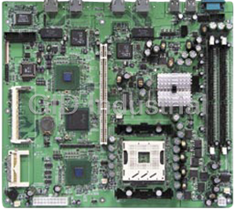
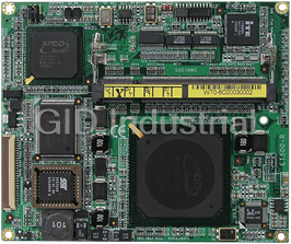
Socket LGA775 Pentium 4 ATI RS400 Mini ITX Industrial Motherboard
Part Number
MB877
Price
Request Quote
Manufacturer
IBASE
Lead Time
Request Quote
Category
Single Board Computers
Specifications
Form Factor
Mini ITX
Ethernet Chipset
Marvell 88E8052
Audio
Built-in audio + AC97 codec
BIOS
Award
Chipset
ULi M1573, Winbond W83627EHF 1x IDE (UDMA100/133), 1x FDD, 1x KB, 1x Mouse 4x RS-232, 2x SATA
Connector
RJ-45 o
Controller
Marvell 88E8052 PCI Express Gigabit LAN
CPU
LGA775 for Pentium 4 / Celeron D, up to 3.8GHz
Expansion Slot
1 PCI
H/W Monitor
Yes
LCD Interface
N/A
Others
IrDA, TV-out, Digital I/O (4-in/4-out)n board
System Chipset
ATi RS400 + ULi M1573 chipset, 533MHz/800MHz FSB
System Memory
DDR2 DIMM x 2, Max. 2GB
USB
4 ports on board (USB 2.0)
VGA Controller
ATi RS400 integrated Radeon M10+, supports CRT or TV-out
VGA Memory
Shared Memory Max. 256MB
Watchdog Timer
256 levels
Features
- 4 x USB 2.0, 4 x COM ports
- DDR2 DIMM x 2, Max. 2GB
- Digital I/O, 2 x SATA, 1 x PCI slot, AC97
- ntegrated ATi Radeon Xpress 200 Series
- PCI Express Gigabit LAN controller
- Supports Pentium 4 / Celeron D processors Up to 3.8GHz, 533MHz/800MHz FSB
- VGA, supports CRT or TV-out
Datasheet

Extracted Text
MB877
®
Socket LGA775 Pentium 4
ATI RS400 Mini ITX
Industrial Motherboard
USER’S MANUAL
Version 1.0A
Acknowledgments
Award is a registered trademark of Award Software International,
Inc.
PS/2 is a trademark of International Business Machines
Corporation.
Intel and Pentium 4 are registered trademarks of Intel
Corporation.
Microsoft Windows is a registered trademark of Microsoft
Corporation.
Winbond is a registered trademark of Winbond Electronics
Corporation.
All other product names or trademarks are properties of their
respective owners.
ii MB877 User’s Manual
Table of Contents
Introduction .......................................................1
Checklist..............................................................................1
Product Description.............................................................2
Specifications ......................................................................3
Board Dimensions...............................................................4
Installations .......................................................5
Installing the CPU ...............................................................6
ATX Power Installation ......................................................7
Installing the Memory .........................................................7
Setting the Jumpers .............................................................8
Connectors on MB877 ......................................................11
Watchdog Timer Configuration ........................................21
BIOS Setup.......................................................25
Drivers Installation ......................................45
Appendix ...........................................................51
A. I/O Port address Map....................................................51
B. Interrupt Request Lines (IRQ)......................................52
C. Digital I/O Sample Code ..............................................53
MB877 User’s Manual iii
This page is intentionally left blank.
iv MB877 User’s Manual
INSTALLATIONS
Introduction
Checklist
®
Your MB877 Pentium 4 motherboard package should include the items
listed below:
Your MB877 package should include the items listed below.
• The MB877 P4 Mini ITX Board
• This User’s Manual
• 1 CD Containing Chipset Drivers And Flash Memory Utility
• ULI SATA/RAID Controller Driver
• Optional cables such as:
• 1 Slim FDD Ribbon Cable
• 1 IDE Ribbon Cable (40-Pin)
• 1 COM Port Cable (For COM2/3/4)
• Serial ATA Cable
MB877 User’s Manual 1
INSTALLATIONS
Product Description
®
The MB877 LGA 775 Pentium 4 motherboard incorporates the ATI
RS400 chipset that can utilize a single LGA775 processor of up to
3.8+GHz or higher and supports FSB frequency of
400MHz/533MHz/800MHz (133MHz, and 200MHz HCLK
respectively).
®
The ATI RS400 chipset is designed for use with the Pentium 4
processor with 1M Level 2 (CPU integrated) cache. The integrated MCH
component provides the CPU interface, DDR2 interface, Hub Interface
and PCI Express interface.
Two dual channel DDR2 memory sockets supports DDR2 400/533/667
SDRAM DIMM modules with up to 2GB in capacity.
The MB877 Mini ITX motherboard supports CRT VGA interface as
well as TV out. The board is designed with one Marvell 88E8052 PCI
Express Gigabit LAN single controllers. The board also has AC97 6CH
audio, 4 COM ports, UDMA 100, 4 USB ports, two serial ATA ports,
watchdog timer, 4 In/4 Out Digital I/O and a PCI slot for expandability.
Dimensions of the board are 170mm x 170mm.
This board represents the perfect choice for those who want superior
performance for POS, kiosk, ATM, Web payphone, medical and other
embedded applications.
2 MB877 User’s Manual
INSTALLATIONS
Specifications
Product Name MB877
® ®
CPU Support Intel Pentium 4
CPU Voltage 0.8375V~1.6V (VRD 10.1)
System Speed Up to 3.8GHz+
CPU Operating 400MHz/533MHz/800MHz
Frequency
Green /APM APM1.2
CPU Socket LGA 775
Chipset Chipset
NB: ATI RS400
SB: ULi M1573
BIOS Award BIOS; Supports ACPI
Cache 1M Level 2 (CPU integrated)
VGA ATI RS400 built-in Mobility Radeon 9600(M10)
Graphic core. Supports AGP 8X,CRT.TV-out
PCI Express Gigabit Marvell 88E8052 PCI Express Gigabit LAN single
LAN controller
Audio ULi M1573 Built-in Sound controller + AC97 Codec
ALC655 6 Channel (Line-in, Line-out, Mic.), On board
D-SUB connector
Memory type 2x DDR2 400/533/667 SDRAM DIMM module (without
ECC function), Max. 2GB (Dual Channel)
LPC I/O 1. First I/O: Winbond 83627EHF: IrDAx1 Parallel x1,
COM1 (RS-232), COM2(RS-232), FDC 1.44MB
(Slim type), Hardware monitor (3 thermal inputs, 8
voltage monitor inputs, VID0-5, 1 chassis open
detection, 3 fan headers)
2. Secondary I/O: Fintek F81216 support COM3, 4
(RS-232)
RTC/CMOS Built in ULi M1573
Battery Lithium battery
Keyboard Controller Built-in Winbond 83627EHF
IDE M1573 built in, IDE1 (40-pin/2.5mm pitch); supports Ultra
DMA 33/66/100
Serial ATA connector ULi M1573 built-in two SATA ports
On board D-type PS/2 Keyboard/Mouse, VGA (CRT), COM1, Printer,
connector USBx2, RJ-45, Line-out, Line-in, Mic, TV-out
Power Connector ATX 24-pin
Expansion Slots 1 slot (supports 2 bus master)
USB 2.0 Supports 4 ports (D-type CN. x2 & pin header x2)
Digital I/O 4 In, 4 Out
Watchdog Timer Supports 256 segments (0,1,2…255. sec/min)
System Voltages +5V, +12V, -12V, 5VSB, -5V, 3.3V
Board Size 170 x170mm
MB877 User’s Manual 3
INSTALLATIONS
Board Dimensions
4 MB877 User’s Manual
INSTALLATIONS
Installations
This section provides information on how to use the jumpers and
connectors on the MB877 in order to set up a workable system. The
topics covered are:
Installing the CPU........................................................................ 6
ATX Power Installation ............................................................... 7
Installing the Memory.................................................................. 7
Setting the Jumpers ...................................................................... 8
Connectors on MB877 ............................................................... 11
Watchdog Timer Configuration................................................. 21
MB877 User’s Manual 5
INSTALLATIONS
Installing the CPU
The MB877 motherboard supports an LGA 775 processor socket for
Intel® Pentium® 4 processors.
The LGA 775 processor socket comes with a lever to secure the
processor. Refer to the pictures below, from left to right, on how to place
the processor into the CPU socket. Please note that the cover of the
LGA775 socket must always be installed during transport to avoid
damage to the socket.
6 MB877 User’s Manual
INSTALLATIONS
ATX Power Installation
The system power is provided to the motherboard with the ATX1 and
ATX_12V1 power connectors. ATX1 is a 24-pin power connector and
ATX_12V1 is a 4-pin 12V power connector.
The 24-pin power connector can to be connected to a standard 20-pin
ATX power connector in a standard ATX power supply (Min. 400watt).
Note: The power supply 5VSB voltage must be at least 2A.
Installing the Memory
The MB877 motherboard supports two DDR2 memory sockets for a
maximum total memory of 2GB in DDR2 memory type. It supports
DDR2 400/533/667 when installed with CPUs that have clock speeds of
533MHz. The board provides dual channel functionality for its DIMM
slots. DIMM1 is for one channel and DIMM2 is for another channel.
Basically, the system memory interface has the following features:
Supports two 64-bit wide DDR2 data channels
Available bandwidth up to 3.2GB/s (DDR2 400) for single-channel
mode and 6.4GB/s (DDR2 400) in dual-channel mode.
Supports 128Mb, 256Mb, 512Mb, 1Gb DDR2 technologies.
Supports only x8, x16, DDR2 devices with four banks
Registered DIMMs not supported
Supports opportunistic refresh
Up to 16 simultaneously open pages (four per row, four rows
maximum)
MB877 User’s Manual 7
INSTALLATIONS
Setting the Jumpers
Jumpers are used on MB877 to select various settings and features
according to your needs and applications. Contact your supplier if you
have doubts about the best configuration for your needs. The following
lists the connectors on MB877 and their respective functions.
Jumper Locations on MB877.......................................................... 9
JP1: COM3 RS232 +5V/+12V Power Setting.............................. 10
JP2: COM4 RS232 +5V/+12V Power Setting.............................. 10
JP4: Clear CMOS Contents .......................................................... 10
8 MB877 User’s Manual
INSTALLATIONS
Jumper Locations on MB877
Jumper Locations on MB877 ...........................................................Page
JP1: COM3 RS232 +5V/+12V Power Setting .................................... 10
JP2: COM4 RS232 +5V/+12V Power Setting .................................... 10
JP4: Clear CMOS Contents ................................................................. 10
MB877 User’s Manual 9
INSTALLATIONS
JP1: COM3 RS232 +5V/+12V Power Setting
JP1 Setting Function
Pin 1-2
+12V
Short/Closed
Pin 3-4
Normal
Short/Closed
Pin 5-6
+5V
Short/Closed
JP2: COM4 RS232 +5V/+12V Power Setting
JP2 Setting Function
Pin 1-2
+12V
Short/Closed
Pin 3-4
Normal
Short/Closed
Pin 5-6
+5V
Short/Closed
JP4: Clear CMOS Contents
Note: the ATX-power connector should be disconnected from the
motherboard before clearing CMOS.
JP4 Setting Function
Pin 1-2
Normal
Short/Closed
Pin 2-3
Clear CMOS
Short/Closed
10 MB877 User’s Manual
INSTALLATIONS
[
Connectors on MB877
The connectors on MB877 allows you to connect external devices such
as keyboard, floppy disk drives, hard disk drives, printers, etc. The
following table lists the connectors on MB877 and their respective
functions.
Connector Locations on MB877 .................................................. 12
ATX1: ATX Power Supply Connector ........................................ 13
ATX_12V1: ATX 12V Power Connector.................................... 13
DIMM1: Channel A DDR2 Socket .............................................. 13
DIMM2: Channel B DDR2 Socket .............................................. 13
PCI1: PCI Slots ............................................................................ 13
CN1: PS/2 Keyboard and PS/2 Mouse Connectors...................... 14
CN2: RJ45 Connector .................................................................. 14
CN3, CN4: Serial ATA (SATA) Connectors ............................... 14
CN5: Line In, Line Out, Mic Connector ...................................... 14
CN6: Floppy Drive Connector ..................................................... 15
J1: IrDA Connector ...................................................................... 15
J2: USB Connector (USB1/USB2)............................................... 15
J3: Serial Ports (COM1, RS232) .................................................. 16
J4: Digital I/O Connector (4 in, 4 out) ......................................... 16
J5: Parallel Port Connector........................................................... 16
J6: VGA CRT Connector ............................................................. 17
J7: Serial Ports (COM2,3,4) ......................................................... 17
J8:TV-Out connector (RCA Jack)................................................ 18
J9: USB Connector (USB3/USB4)............................................... 18
J10: System Function Connector.................................................. 18
J11: Wake On LAN Connector .................................................... 18
J12: CD-In Audio Connector ....................................................... 18
JP5: Power LED Connector ......................................................... 19
JP6: Speaker Connector................................................................ 19
CPU_FAN1: CPU Fan Power Connector.................................... 19
FAN1: System & Chassis Fan Power Connectors........................ 19
IDE1: Primary IDE Connectors.................................................... 20
MB877 User’s Manual 11
INSTALLATIONS
Connector Locations on MB877
Connectors on MB877..............................................................................................................Page
ATX1: ATX Power Supply Connector..................................................................................................................13
ATX_12V1: ATX 12V Power Connector .............................................................................................................13
DIMM1: Channel A DDR2 Socket........................................................................................................................13
DIMM2: Channel B DDR2 Socket........................................................................................................................13
PCI1: PCI Slots ......................................................................................................................................................13
CN1: PS/2 Keyboard and PS/2 Mouse Connectors ...............................................................................................14
CN2: RJ45 Connector............................................................................................................................................14
CN3, CN4: Serial ATA (SATA) Connectors.........................................................................................................14
CN5: Line In, Line Out, Mic Connector ................................................................................................................14
CN6: Floppy Drive Connector...............................................................................................................................15
J1: IrDA Connector................................................................................................................................................15
J2: USB Connector (USB1/USB2) ........................................................................................................................15
J3: Serial Ports (COM1, RS232)............................................................................................................................16
J4: Digital I/O Connector (4 in, 4 out) ...................................................................................................................16
J5: Parallel Port Connector ....................................................................................................................................16
J6: VGA CRT Connector.......................................................................................................................................17
J7: Serial Ports (COM2,3,4)...................................................................................................................................17
J8:TV-Out Connector (RCA Jack).........................................................................................................................18
J9: USB Connector (USB3/USB4) ........................................................................................................................18
J10: System Function Connector ...........................................................................................................................18
J11: Wake On LAN Connector..............................................................................................................................18
J12: CD-In Audio Connector .................................................................................................................................18
JP5: Power LED Connector ...................................................................................................................................19
JP6: Speaker Connector .........................................................................................................................................19
CPU_FAN1: CPU Fan Power Connector .............................................................................................................19
FAN1: System & Chassis Fan Power Connectors .................................................................................................19
IDE1: Primary IDE Connectors .............................................................................................................................20
12 MB877 User’s Manual
INSTALLATIONS
ATX1: ATX Power Supply Connector
Signal Name Pin # Pin # Signal Name
3.3V 13 1 3.3V
-12V 14 2 3.3V
Ground 15 3 Ground
PS-ON 16 4 +5V
Ground 17 5 Ground
Ground 18 6 +5V
Ground 19 7 Ground
-5V 20 8 Power good
+5V 21 9 5VSB
+5V 22 10 +12V
+5V 23 11 +12V
Ground 24 12 +3.3V
ATX1 is a 24-pin ATX power supply connector.
ATX_12V1: ATX 12V Power Connector
This connector supplies the CPU operation voltage
Pin # Signal Name
1 Ground
2 Ground
3 +12V
4 +12V
DIMM1: Channel A DDR2 Socket
DIMM1 is the first-channel DDR2 socket.
DIMM2: Channel B DDR2 Socket
DIMM2 is the second-channel DDR2 socket.
PCI1: PCI Slots
MB877 User’s Manual 13
INSTALLATIONS
CN1: PS/2 Keyboard and PS/2 Mouse Connectors
PS/2 Mouse
PS/2 Keyboard
Signal Name Keyboard Mouse Signal Name
Keyboard data 1 1 Mouse data
N.C. 2 2 N.C.
GND 3 3 GND
5V 4 4 5V
Keyboard clock 5 5 Mouse clock
N.C. 6 6 N.C.
CN2: RJ45 Connector
CN3, CN4: Serial ATA (SATA) Connectors
The SATA connectors support serial ATA 150. Each connector can only
use one serial ATA hard disk. CN4 is port 1 and CN3 is port 2.
CN5: Line In, Line Out, Mic Connector
14 MB877 User’s Manual
INSTALLATIONS
CN6: Floppy Drive Connector
CN6 is a slim 26-pin connector and will support up to 2.88MB FDD.
Signal Name Pin # Pin # Signal Name
VCC 1 2 INDEX
VCC 3 4 DRV_SEL
VCC 5 6 DSK_CH
NC 7 8 NC
NC 9 10 MOTOR
DINST 11 12 DIR
NC 13 14 STEP
GND 15 16 WDATA
GND 17 18 WGATE
GND 19 20 TRACK
NC 21 22 WPROT
GND 23 24 RDATA
GND 25 26 SIDE
J1: IrDA Connector
Pin # Signal Name
1 +5V
2 No connect
3 Ir RX
4 Ground
5 Ir TX
J2: USB Connector (USB1/USB2)
J2 is a stacked USB port.
USB0
Pin # Signal Name
1 Vcc
2 USB-
3 USB+
USB1
4 Ground
MB877 User’s Manual 15
INSTALLATIONS
J3: Serial Ports (COM1, RS232)
Signal Name Pin # Pin # Signal Name
DCD, Data carrier detect 1 6 DSR, Data set ready
RXD, Receive data 2 7 RTS, Request to send
TXD, Transmit data 3 8 CTS, Clear to send
DTR, Data terminal ready 4 9 RI, Ring indicator
GND, ground 5 10 Not Used
J4: Digital I/O Connector (4 in, 4 out)
This 10-pin Digital I/O connector supports TTL levels and is used to
control external devices requiring ON/OFF circuitry.
Signal Name Pin # Pin # Signal Name
Ground 1 2 +5V
Out3 3 4 Out1
Out2 5 6 Out0
IN3 7 8 IN1
IN2 9 10 IN0
J5: Parallel Port Connector
J5 Parallel Port
Signal Name Pin # Pin # Signal Name
Line printer strobe 1 14 AutoFeed
PD0, parallel data 0 2 15 Error
PD1, parallel data 1 3 16 Initialize
PD2, parallel data 2 4 17 Select
PD3, parallel data 3 5 18 Ground
PD4, parallel data 4 6 19 Ground
PD5, parallel data 5 7 20 Ground
PD6, parallel data 6 8 21 Ground
PD7, parallel data 7 9 22 Ground
ACK, acknowledge 10 23 Ground
Busy 11 24 Ground
Paper empty 12 25 Ground
Select 13 N/A N/A
16 MB877 User’s Manual
INSTALLATIONS
J6: VGA CRT Connector
J6 is a DB-15 VGA connector located beside the COM1 port. The
following table shows the pin-out assignments of this connector.
Signal Name Pin # Pin # Signal Name
Red 1 2 Green
Blue 3 4 N.C.
GND 5 6 GND
GND 7 8 GND
N.C. 9 10 GND
N.C. 11 12 N.C.
HSYNC 13 14 VSYNC
NC 15
J7: Serial Ports (COM2,3,4)
J7 is a 30-pin header for the board’s serial ports (RS232).
Signal Name Pin # Pin # Signal Name
DCD2 1 2 DSR2
SIN2 3 4 RTS2
SO2 5 6 CTS2
DTR2- 7 8 RI2
GND 9 10 N/A
DCD3 11 12 DSR3
SIN3 13 14 RTS3
SOUT3 15 16 CTS3
DTR3 17 18 RI3-
GND 19 20 N/A
DCD4 21 22 DSR4
SIN4 23 24 RTS4
SOUT4 25 26 CTS4
DTR4 27 28 RI4
GND 29 30 N/A
MB877 User’s Manual 17
INSTALLATIONS
J8: TV-Out connector (RCA Jack)
J9: USB Connector (USB3/USB4)
The following table shows the pin outs of the USB pin headers
connectors (USB 2.0 compliant).
Signal Name Pin Pin Signal Name
Vcc 1 5 Ground
USB0- 2 6 USB1+
USB0+ 3 7 USB1-
Ground 4 8 Vcc
J10: System Function Connector
Signal Name Pin Pin Signal Name
Gnd 1 2 PS_ON
5V 3 4 HDD Active
Ground 5 7 Reset
ATX power on switch: Pins 1-2
HDD LED: Pins 3-4
Reset switch: Pins 5-6
J11: Wake On LAN Connector
J11 is a 3-pin header for the Wake On LAN function on the
motherboard. The following table shows the pin out assignments of this
connector. Wake On LAN will function properly only with an ATX
power supply with 5VSB that has 1A.
Pin # Signal Name
1 +5VSB
2 Ground
3 LAN Wakeup
J12: CD-In Audio Connector
Pin # Signal Name
1 CD Audio R
2 Ground
3 Ground
4 CD Audio L
18 MB877 User’s Manual
INSTALLATIONS
JP5: Power LED Connector
Pin # Signal Name
1 Vcc
2 NC
3 Power LED
JP6: Speaker Connector
Pin # Signal Name
1 Speaker
2 NC
3 NC
4 VCC
CPU_FAN1: CPU Fan Power Connector
Pin # Signal Name
1 Ground
2 +12V
3 Rotation detection
4 Control
FAN1: System & Chassis Fan Power Connectors
Pin # Signal Name
1 Ground
2 +12V
3 Rotation detection
MB877 User’s Manual 19
INSTALLATIONS
IDE1: Primary IDE Connectors
Signal Name Pin # Pin # Signal Name
Reset IDE 1 2 Ground
Host data 7 3 4 Host data 8
Host data 6 5 6 Host data 9
Host data 5 7 8 Host data 10
Host data 4 9 10 Host data 11
Host data 3 11 12 Host data 12
Host data 2 13 14 Host data 13
Host data 1 15 16 Host data 14
Host data 0 17 18 Host data 15
Ground 19 20 Protect pin
DRQ0 21 22 Ground
Host IOW 23 24 Ground
Host IOR 25 26 Ground
IOCHRDY 27 28 Host ALE
DACK0 29 30 Ground
IRQ14 31 32 No connect
IDE1 ADDR2ess 1 33 34 No connect
ADDR2ess 0 35 36 ADDR2ess 2
Chip select 0 37 38 Chip select 1
Activity 39 40 Ground
20 MB877 User’s Manual
INSTALLATIONS
Watchdog Timer Configuration
The WDT is used to generate a variety of output signals after a user
programmable count. The WDT is suitable for use in the prevention of
system lock-up, such as when software becomes trapped in a deadlock.
Under these sort of circumstances, the timer will count to zero and the
selected outputs will be driven. Under normal circumstance, the user
will restart the WDT at regular intervals before the timer counts to zero.
SAMPLE CODE:
This code and information is provided "as is" without warranty of any
kind, either expressed or implied, including but not limited to the
implied warranties of merchantability and/or fitness for a particular
purpose.
;[]================================================
; Name : Enable_And_Set_Watchdog
; IN : AL - 1sec ~ 255sec
; OUT : None
;[]================================================
Enable_And_Set_Watchdog Proc Near
push ax ;save time interval
call Unlock_Chip
mov cl, 2Bh
call Read_Reg
and al, NOT 10h
call Write_Reg ;set GP24 as WDTO
mov cl, 07h
mov al, 08h
call Write_Reg ;switch to LD8
mov cl, 0F5h
call Read_Reg
and al, NOT 08h
call Write_Reg ;set count mode as second
pop ax
mov cl, 0F6h
call Write_Reg ;set watchdog timer
mov al, 01h
mov cl, 30h
call Write_Reg ;watchdog enabled
MB877 User’s Manual 21
INSTALLATIONS
call Lock_Chip
ret
Enable_And_Set_Watchdog Endp
;[]===============================================
; Name : Disable_Watchdog
; IN : None
; OUT : None
;[]===============================================
Disable_Watchdog Proc Near
call Unlock_Chip
mov cl, 07h
mov al, 08h
call Write_Reg ;switch to LD8
xor al, al
mov cl, 0F6h
call Write_Reg ;clear watchdog timer
xor al, al
mov cl, 30h
call Write_Reg ;watchdog disabled
call Lock_Chip
ret
Disable_Watchdog Endp
;[]===============================================
; Name : Unlock_Chip
; IN : None
; OUT : None
;[]===============================================
Unlock_Chip Proc Near
mov dx, 4EH
mov al, 87h
out dx, al
out dx, al
ret
Unlock_Chip Endp
;[]================================================
; Name : Lock_Chip
; IN : None
; OUT : None
22 MB877 User’s Manual
INSTALLATIONS
;[]================================================
Unlock_Chip Proc Near
mov dx, 4EH
mov al, 0Aah
out dx, al
ret
Unlock_Chip Endp
;[]================================================
; Name : Write_Reg
; IN : CL - register index
; AL - Value to write
; OUT : None
;[]================================================
Write_Reg Proc Near
push ax
mov dx, 4EH
mov al,cl
out dx,al
pop ax
inc dx
out dx,al
ret
Write_Reg Endp
;[]================================================
; Name : Read_Reg
; IN : CL - register index
; OUT : AL - Value to read
;[]===================================================
Read_Reg Proc Near
mov al, cl
mov dx, 4EH
out dx, al
inc dx
in al, dx
ret
Read_Reg Endp
;[]================================================
MB877 User’s Manual 23
INSTALLATIONS
This page is intentionally left blank.
24 MB877 User’s Manual
BIOS SETUP
BIOS Setup
This chapter describes the different settings available in the Award
BIOS that comes with the motherboard. The topics covered in this
chapter are as follows:
BIOS Introduction ........................................................................ 26
BIOS Setup................................................................................... 26
Standard CMOS Setup ................................................................. 28
Advanced BIOS Features ............................................................. 30
Advanced Chipset Features .......................................................... 34
Integrated Peripherals................................................................... 36
Power Management Setup............................................................ 38
PNP/PCI Configurations .............................................................. 41
PC Health Status........................................................................... 42
Frequency/Voltage Control .......................................................... 43
Load Fail-Safe Defaults................................................................ 44
Load Setup Defaults ..................................................................... 44
Set Password ................................................................................ 44
Save & Exit Setup ........................................................................ 44
Exit Without Saving ..................................................................... 44
MB877 User’s Manual 25
BIOS SETUP
BIOS Introduction
The Award BIOS (Basic Input/Output System) installed in your
® ®
computer system’s ROM supports Intel Pentium 4 processors. The
BIOS provides critical low-level support for a standard device such as
disk drives, serial ports and parallel ports. It also adds virus and
password protection as well as special support for detailed fine-tuning of
the chipset controlling the entire system.
BIOS Setup
The Award BIOS provides a Setup utility program for specifying the
system configurations and settings. The BIOS ROM of the system stores
the Setup utility. When you turn on the computer, the Award BIOS is
immediately activated. Pressing the key immediately allows you
to enter the Setup utility. If you are a little bit late pressing the
key, POST (Power On Self Test) will continue with its test routines, thus
preventing you from invoking the Setup. If you still wish to enter Setup,
restart the system by pressing the ”Reset” button or simultaneously
pressing the to Enter Setup
In general, you press the arrow keys to highlight items,
Frequently asked questions
How does Industrial Trading differ from its competitors?

Is there a warranty for the MB877?
Which carrier will Industrial Trading use to ship my parts?
Can I buy parts from Industrial Trading if I am outside the USA?
Which payment methods does Industrial Trading accept?
Why buy from GID?

Quality
We are industry veterans who take pride in our work

Protection
Avoid the dangers of risky trading in the gray market

Access
Our network of suppliers is ready and at your disposal

Savings
Maintain legacy systems to prevent costly downtime

Speed
Time is of the essence, and we are respectful of yours
Related Products

Request a Quote

The quote request has been received
Close

Facing challenges or have inquiries? Feel free to contact us!
Call Us +1-469-283-2440
What they say about us
FANTASTIC RESOURCE
One of our top priorities is maintaining our business with precision, and we are constantly looking for affiliates that can help us achieve our goal. With the aid of GID Industrial, our obsolete product management has never been more efficient. They have been a great resource to our company, and have quickly become a go-to supplier on our list!
Bucher Emhart Glass
EXCELLENT SERVICE
With our strict fundamentals and high expectations, we were surprised when we came across GID Industrial and their competitive pricing. When we approached them with our issue, they were incredibly confident in being able to provide us with a seamless solution at the best price for us. GID Industrial quickly understood our needs and provided us with excellent service, as well as fully tested product to ensure what we received would be the right fit for our company.
Fuji
HARD TO FIND A BETTER PROVIDER
Our company provides services to aid in the manufacture of technological products, such as semiconductors and flat panel displays, and often searching for distributors of obsolete product we require can waste time and money. Finding GID Industrial proved to be a great asset to our company, with cost effective solutions and superior knowledge on all of their materials, it’d be hard to find a better provider of obsolete or hard to find products.
Applied Materials
CONSISTENTLY DELIVERS QUALITY SOLUTIONS
Over the years, the equipment used in our company becomes discontinued, but they’re still of great use to us and our customers. Once these products are no longer available through the manufacturer, finding a reliable, quick supplier is a necessity, and luckily for us, GID Industrial has provided the most trustworthy, quality solutions to our obsolete component needs.
Nidec Vamco
TERRIFIC RESOURCE
This company has been a terrific help to us (I work for Trican Well Service) in sourcing the Micron Ram Memory we needed for our Siemens computers. Great service! And great pricing! I know when the product is shipping and when it will arrive, all the way through the ordering process.
Trican Well Service
GO TO SOURCE
When I can't find an obsolete part, I first call GID and they'll come up with my parts every time. Great customer service and follow up as well. Scott emails me from time to time to touch base and see if we're having trouble finding something.....which is often with our 25 yr old equipment.
ConAgra Foods