

 Manufacturers
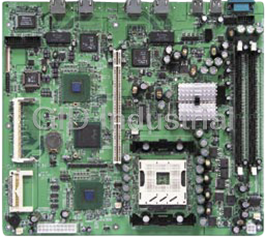
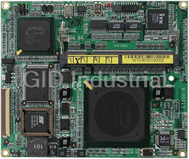
IBASE IP350G

Description
3U CompactPCI ETX Baseboard with dual 10/100 Ethernet
Part Number
IP350G
Price
Request Quote
Manufacturer
IBASE
Lead Time
Request Quote
Category
Single Board Computers
Specifications
Form Factor
ETX
3U CompactPCI
Board Dimensions
160mm x 100mm
Display
VGA DB15 CRT connector on front side;LVDS panel signals on J2 rear side CPCI connector
LAN
two 10/100Mbps LAN (Intel 82551) or two Gigabit LAN (Intel 82540)
Operating Temperature
0°C~60°C (32°F~140°F)
Relative Humidity
10%~90% (non-condensing)
Storage
Ultra160 SCSI LSI 53C1000 controller 68-pin SCSI connector;IDE Primary;Secondary IDE;Compact Flash Socket
Storage Temperature
-20°C~80°C (-7°F~4°F)
Features
- 160mm x 100mm Board Size
- 6 PCB Layers
- CF Card Socket for Type I Cards
- COM1 and COM2 Connectors
- DB15 VGA Connector
- Dual 10/100Mbps LAN or dual Gigabit LAN on board
- Dual Gigabit or 10/100Mbps RJ45 Connectors
- Dual IDE channels
- LSI 53C1000 SCSI Controller (160MB/s)
- LVDS Panel Signal (rear side)
- One 10/100Mbps RJ45 Connector
- PS/2 type Keyboard and Mouse Connectors
- TI Ti2150 PCI to PCI Bridge
Datasheet

Extracted Text
IP350 3U CompactPCI ETX Base Board USER’S MANUAL Version 1.0 Acknowledgments PS/2 are trademarks of International Business Machines Corporation. Microsoft Windows is a registered trademark of Microsoft Corporation. Winbond is a registered trademark of Winbond Electronics Corporation. All other product names or trademarks are properties of their respective owners. Please Note The manufacturer provides these documents as the latest version for the revision indicated. The material is subject to change without notice. ii IP350 User’s Manual Table of Contents Introduction........................................................1 Product Description ..........................................................1 Checklist...........................................................................2 Board Dimensions.............................................................3 Installations........................................................5 Setting the Jumpers...........................................................6 Connectors on IP350.......................................................10 Drivers Installation .......................................19 Intel PRO LAN Drivers Installation.................................20 SCSI Drivers Installation ................................................21 Installing SCSI Driver for Windows 95/98 .........................21 SCSI Driver Installation for Windows 2000 .......................22 SCSI Driver Installation for Windows NT...........................23 IP350 User’s Manual iii This page was intentionally left blank. iv IP350 User’s Manual INTRODUCTION Introduction Product Description The IP350 3U CompactPCI ETX baseboard is designed for ETX CPU modules as an interface platform. It packs all the PC connectors for the ETX CPU module to be a high-performance functional embedded board. The IP350 includes the following features: · Dual 10/100Mbps LAN or dual Gigabit LAN on board · TI Ti2150 PCI to PCI Bridge · LSI 53C1000 SCSI Controller (160MB/s) · Dual Gigabit or 10/100Mbps RJ45 Connectors · One 10/100Mbps RJ45 Connector · Dual IDE channels · PS/2 type Keyboard and Mouse Connectors · DB15 VGA Connector · LVDS Panel Signal (rear side) · CF Card Socket for Type I Cards · COM1 and COM2 Connectors · 6 PCB Layers · 160mm x 100mm Board Size The board has three RJ45 connectors on board. One of them supports the Ethernet function featured on the ETX module that is used. Another two connectors support either two 10/100Mbps LAN or two Gigabit LAN on the baseboard. The IP350 comes with an extension interface card that sits on top of the first layer connectors. The card is IP350R which has connectors for rd th printer port, 3 and 4 USB connectors, COM1 D-sub connector and COM2 serial port pin header. The Compact Flash connector on board is for CompactFlash Type I memory cards. A Compact Flash memory card is a solid state disk card with a 50pin connector. The pins provide a connection between the memory and the Compact Flash drive. Compact Flash cards are designed with flash technology, a non-volatile storage solution that does not lose its information once power is removed from the card. The cards contain no moving parts and are extremely rugged, providing much greater protection of data than conventional magnetic disk drives. IP350 User’s Manual 1 INTRODUCTION Checklist Your IP350 package should include the items listed below. Damaged or missing items should be reported to your supplier. · The IP350 3U CompactPCI Baseboard · The IP350R Daughter Board · One CD disk containing the necessary drivers · Standard /optional cables such as: · 1 44-pin IDE Ribbon Cable · 1 COM Port Cable (optional) · 1 Printer Port Cable (optional) · 1 PS/2 Keyboard/Mouse Cable · 1 26-pin FDD Flat Cable 2 IP350 User’s Manual INTRODUCTION Board Dimensions IP350 User’s Manual 3 INTRODUCTION This page is intentionally left blank. 4 IP350 User’s Manual INSTALLATIONS Installations This section provides information on how to use the jumpers and connectors on the IP350 in order to set up a workable system. The topics covered are: Setting the Jumpers .......................................................................... 6 Connectors on IP350 .....................................................................10 IP350 User’s Manual 5 INSTALLATIONS Setting the Jumpers Jumpers are used on the IP350 to select various settings and features according to your needs and applications. Contact your supplier if you have doubts about the best configuration for your needs. The following lists the connectors on IP350 and their respective functions. Jumper Locations on IP350 ................................................................ 7 JP1: CF Socket Master/Slave Select................................................... 8 JP2: Reserved....................................................................................... 8 JP3: SCSI Terminator Enable/Disable................................................ 8 JP4: ETX Module Selection................................................................ 8 JP5: PCI to PCI Bridge Enable/Disable ............................................. 9 JP6: Secondary LAN Enable / Disable ............................................... 9 JP7: Primary LAN Enable / Disable ................................................... 9 JP8: Reserved....................................................................................... 9 JP9: System Power Good Enable/Disable.......................................... 9 6 IP350 User’s Manual INSTALLATIONS Jumper Locations on IP350 Jumpers on IP350 JP1: CF Socket Master/Slave Select JP2: Reserved JP3: SCSI Terminator Enable/Disable JP4: ETX Module Selection JP5: PCI to PCI Bridge Enable/Disable JP6: Secondary LAN Enable / Disable JP7: Primary LAN Enable / Disable JP8: Reserved JP9: System Power Good Enable/Disable NOTE: Before installing the ETX CPU module, make sure of the pin orientation of both the ETX interface connectors and the ETX module connector before plugging the module. Once the module is slightly plugged in, use an even force to fully plug in the module. IP350 User’s Manual 7 INSTALLATIONS JP1: CF Socket Master/Slave Select JP1 Setting Function Short/Closed Master Open Slave JP2: Reserved JP3: SCSI Terminator Enable/Disable JP3 Setting SCSI Terminator Pin 1-2 Enabled Short/Closed Pin 2-3 Auto Short/Closed Disabled Pins Open JP4: ETX Module Selection JP4 Setting ETX Module Used Other ETX Modules Pin 1-2 (Default ) Short/Closed Pin 2-3 ET815 Short/Closed 8 IP350 User’s Manual INSTALLATIONS JP5: PCI to PCI Bridge Enable/Disable JP5 Setting PCI to PCI Bridge Pin 1-2 Disable Short/Closed Pin 2-3 Enabled (Default) Short/Closed JP6: Secondary LAN Enable / Disable JP6 Setting Secondary LAN Pin 1-2 Enabled Short/Closed Pin 2-3 Disabled Short/Closed JP7: Primary LAN Enable / Disable JP7 Setting Primary LAN Pin 1-2 Enabled Short/Closed Pin 2-3 Disabled Short/Closed JP8: Reserved JP9: System Power Good Enable/Disable JP9 Setting Function Short/Closed Enabled (Default) Open Disabled IP350 User’s Manual 9 INSTALLATIONS Connectors on IP350 The connectors on IP350 allows you to connect external devices such as keyboard, floppy disk drives, hard disk drives, printers, etc. The following table lists the connectors on IP350 and their respective functions. Connector Locations on IP350 / IP350R.........................................11 J1: 10/100M RJ45 Connector (on IP350R) ....................................12 J2: Keyboard/Mouse Connector (on IP350R) .................................12 J3: Optional TV Out Connector (on IP350R) .................................12 J4: Printer Port Pin Header (on IP350R) .........................................13 J5: USB2/USB3 Pin Header (on IP350R) .......................................13 J6, J7: COM1 / COM2 Serial Ports (on IP350R)............................13 J1: System Fan Power Connector.....................................................14 J2: IDE Connector.............................................................................14 J3: Dual LAN Connectors.................................................................14 J5: Compact Flash (CF) Socket........................................................15 J7: SCSI Connector (Optional).........................................................15 J8: VGA CRT Connector..................................................................15 st nd USB1, USB2: 1 and 2 USB Connectors......................................15 J1, J2: CompactPCI Slot Connector.................................................16 10 IP350 User’s Manual INSTALLATIONS Connector Locations on IP350 / IP350R Connectors on IP350 J1: 10/100M RJ45 Connector (on IP350R) J2: Keyboard/Mouse Connector (on IP350R) J3: TV Out Connector (on IP350R) J4: Printer Port Pin Header (on IP350R) J5: USB2/USB3 Pin Header (on IP350R) J6, J7: COM1 / COM2 Serial Ports (on IP350R) J1: System Fan Power Connector J2: IDE Connector J3: Dual LAN Connectors J5: Compact Flash (CF) Socket J7: SCSI Connector (Optional) J8: VGA CRT Connector st nd USB1, USB2: 1 and 2 USB Connectors J1, J2: CompactPCI Slot Connector IP350 User’s Manual 11 INSTALLATIONS J1: 10/100M RJ45 Connector (on IP350R) J1 is the RJ45 connector beside the keyboard/mouse PS/2 connector on the IP350R interface daughter board. See below for the respective pin assignments. J2: Keyboard/Mouse Connector (on IP350R) J2 is used with a Y-cable with dual D-connectors to support a PS/2 keyboard and a PS/2 mouse. Pin # Signal Name 1 Keyboard data 2 Mouse data 3 Ground 4 Vcc 5 Keyboard Clock J2 6 Mouse Clock J3: Optional TV Out Connector (on IP350R) Signal Name Pin # Pin # Signal Name Comp 1 2 Ground S-Y 3 4 S-C NC 5 6 NC Comp 7 8 NC NOTE: This connector usable only depending on the system board if the TV out function is supported or not. 12 IP350 User’s Manual INSTALLATIONS J4: Printer Port Pin Header (on IP350R) Signal Name Pin # Pin # Signal Name Line printer strobe 1 2 AutoFeed PD0, parallel data 0 3 4 Error PD1, parallel data 1 5 6 Initialize PD2, parallel data 2 7 8 Select PD3, parallel data 3 9 10 Ground PD4, parallel data 4 11 12 Ground PD5, parallel data 5 13 14 Ground PD6, parallel data 6 15 16 Ground PD7, parallel data 7 17 18 Ground ACK, acknowledge 19 20 Ground Busy 21 22 Ground Paper empty 23 24 Ground Select 25 26 N/A J5: USB2/USB3 Pin Header (on IP350R) Signal Name Pin Pin Signal Name Vcc 1 2 Ground USB2- 3 4 USB3- USB2+ 5 6 USB3+ Ground 7 8 Vcc J6, J7: COM1 / COM2 Serial Ports (on IP350R) J6 (COM1) is a DB-9 connector, while J7 (COM2) is a pin header connector. Refer to the table below for their pin assignments. COM1 COM2 Signal Name Pin # Pin # Signal Name DCD, Data carrier detect 1 6 DSR, Data set ready RXD, Receive data 2 7 RTS, Request to send TXD, Transmit data 3 8 CTS, Clear to send DTR, Data terminal ready 4 9 RI, Ring indicator GND, ground 5 10 Not Used IP350 User’s Manual 13 INSTALLATIONS J1: System Fan Power Connector J1 is a 3-pin header for the system fan. The fan must be a 12V fan. Pin # Signal Name 1 Ground 2 +12V 3 Rotation detection J2: IDE Connector J2 is the 44-pin IDE connector that can connect to your IDE devices. Signal Name Pin # Pin # Signal Name Reset IDE 1 2 Ground Host data 7 3 4 Host data 8 Host data 6 5 6 Host data 9 Host data 5 7 8 Host data 10 Host data 4 9 10 Host data 11 Host data 3 11 12 Host data 12 Host data 2 13 14 Host data 13 Host data 1 15 16 Host data 14 Host data 0 17 18 Host data 15 Ground 19 20 Key DRQ0 21 22 Ground Host IOW 23 24 Ground Host IOR 25 26 Ground IOCHRDY 27 28 Host ALE DACK0 29 30 Ground IRQ14 31 32 No connect Address 1 33 34 No connect Address 0 35 36 Address 2 Chip select 0 37 38 Chip select 1 Activity 39 40 Ground Vcc 41 42 Vcc Ground 43 44 N.C. J3: Dual LAN Connectors The two LAN connectors, supporting either two 10/100 Mbps LAN or two Gigabit LAN controller, are on board the IP350 baseboard side by side to each other. 14 IP350 User’s Manual INSTALLATIONS J5: Compact Flash (CF) Socket J7: SCSI Connector (Optional) J8: VGA CRT Connector The pin assignments of the J8 VGA CRT connector are as follows: Signal Name Pin Pin Signal Name Red 1 2 Green Blue 3 4 N.C. GND 5 6 GND GND 7 8 GND J8 N.C. 9 10 GND N.C. 11 12 N.C. HSYNC 13 14 VSYNC NC 15 st nd USB1, USB2: 1 and 2 USB Connectors The USB1 and USB2 USB connectors are on the IP350 base board and situated between the Gigabit LAN connectors and the VGA CRT connector. USB 1.1 data transfer rate is supported. IP350 User’s Manual 15 INSTALLATIONS J1, J2: CompactPCI Slot Connector J1 CompactPCI Connector Type 2mm (IEC1076-4-101) 110 J1 J1 Pin Assignment Pin # A B C D E (F) 25 5V REQ64# ENUM# 3.3V 5V GND 24 AD[1] 5V V(I/O) AD[0] ACK64# GND 23 3.3V AD[4] AD[3] 5V AD[2] GND 22 AD[7] GND 3.3V AD[6] AD[5] GND 21 3.3V AD[9] AD[8] M66EN C/BE[0]# GND 20 AD[12] GND V(I/O) AD[11] AD[10] GND 19 3.3V AD[15] AD[14] GND AD[13] GND 18 SERR# GND 3.3V PAR C/BE[1]# GND 17 3.3V SDONE SBO# GND PERR# GND 16 DEVSEL# GND V(I/O) STOP# LOCK# GND 15 3.3V FRAME# IRDY# GND TRDY# GND 12-14 KEY AREA 11 AD[18] AD[17] AD[16] GND C/BE[2]# GND 10 AD[21] GND 3.3V AD[20] AD[19] GND 9 C/BE[3]# IDSEL AD[23] GND AD[22] GND 8 AD[26] GND V(I/O) AD[25] AD[24] GND 7 AD[30] AD[29] AD[28] GND AD[27] GND 6 REQ# GND 3.3V CLK AD[31] GND 5 BRSVP1A5 BSVP1B5 RST# GND GNT# GND 4 BRSVP1A4 GND V(I/O) INTP INTS GND 3 INTA# INTB# INTC# 5V INTD# GND 2 TCK 5V TMS TDO TDI GND 1 5V -12V TRST# +12V 5V GND 16 IP350 User’s Manual INSTALLATIONS J2 CompactPCI Connector Type 2mm (IEC1076-4-101) 110 J2 J2 Pin Assignment Pin # A B C D E (F) GA4 IDE-D7 IDE-D15 FPVDDEN GA0 GND 22 CLK6 GND IDE-D14 FPEN RSV GND 21 CLK5 GND IDE-D13 GND IDE-RST GND 20 GND GND IDE-D12 YTX2- IDE-ACTP GND 19 YTXC- IDE-D6 IDE-D11 GND IDE-DIAG GND 18 YTXC+ GND IDE-D10 REQ6# GNT6# GND 17 BRSVP2A16 IDE-D5 IDE-D9 GND IDE-A2 GND 16 BRSVP2A15 GND IDE-D8 REQ5# GNT5# GND 15 Reserved IDE-D4 K/B-CLK GND IDE-A1 GND 14 Reserved GND V(I/O) YTX2+ IDE-A0 GND 13 RI1- IDE-D3 K/B-DAT GND IDE-CS3 GND 12 TXD1 GND V(I/O) YTX1- P66D GND 11 CTS1- IDE-D2 M/S-CLK GND IDE-CS1 GND 10 DSR1- GND V(I/O) YTX1+ IRQ14 GND 9 DCD1- IDE-D1 M/S-DAT GND IDE-DACK GND 8 DTR1- GND V(I/O) YTX0+ IDE-RDY GND 7 RTS1- IDE-D0 Reserved GND IDE-IOR GND 6 RXD1 GND V(I/O) YTX0- IDE-IOW GND 5 V(I/O) BRSVP2B4 Reserved GND IDE-DRQ GND 4 CLK4 GND GNT3# REQ4# GNT4# GND 3 CLK2 CLK3 SYSEN# GNT2# REQ3# GND 2 CLK1 GND REQ1# GNT1# REQ2# GND 1 IP350 User’s Manual 17 INSTALLATIONS This page is intentionally left blank. 18 IP350 User’s Manual Drivers Installation Drivers Installation This section describes the installation procedures for software and drivers under the Windows 98, Windows NT 4.0 and Windows 2000. The software and drivers are included with the motherboard. If you find the items missing, please contact the vendor where you made the purchase. The contents of this section include the following: Intel PRO LAN Drivers Installation..............................................20 SCSI Drivers Installation................................................................21 Installing SCSI Driver for Windows 95/98..........................21 SCSI Driver Installation for Windows 2000........................22 SCSI Driver Installation for Windows NT...........................23 IMPORTANT NOTE: After installing your Windows operating system (Windows 98/98SE/ME/2000/XP), you must install first the Intel Chipset Software Installation Utility before proceeding with the drivers installation. IP350 User’s Manual 19 DRIVERS INSTALLATIONS Intel PRO LAN Drivers Installation The Intel PRO LAN drivers support both Intel® PRO/100 and PRO/1000 drivers. Follow the steps below to complete the installation. 1. Insert the CD that comes with the motherboard and the screen below would appear. Click on LAN Card on the left side to make the LAN drivers selection. Click on Intel(R) PRO LAN Drivers. 2. Click Install Now. 3. Click Restart now to restart the computer and new settings to take effect. 20 IP350 User’s Manual Drivers Installation SCSI Drivers Installation Execute the steps below if your system supports the SCSI function. Installing SCSI Driver for Windows 95/98 A: New Windows 95/98 installation: 1. Run SETUP.EXE from the Windows 95/98 CD-ROM and follow the directions on the screen. 2. After a Windows 95/98 session is established, select My Computer/ Control Panel/System/Device Manager/Other devices/PCI SCSI Bus Controller from the Windows 95/98 desktop. 3. Click the Driver tab, then click the Change Driver tab. 4. Double click SCSI controllers, then click the Have Disk button. 5. Insert the CD disc that has been bundled with your IBD100 card. The location of the SCSI drivers is in the following directory of the CD you received : \SCSI\LSI1000R\WIN9X. 6. Use this as the location of the drivers and follow the instructions on the screen to finish the drivers installation. IP350 User’s Manual 21 DRIVERS INSTALLATIONS SCSI Driver Installation for Windows 2000 Before starting with the installation of the SCSI drivers, you need to copy the necessary files from the CD disc bundled with the card into a floppy diskette. The location of the necessary files in the CD is \SCSI\LSI1000R\WIN2000. Copy all the files in this directory into a floppy diskette. When you install the Windows 2000 operating system, insert the diskette containing the necessary files. To install Windows 2000 from your CDROM drive, make sure that your start up boot drive as set in the BIOS is the CDROM drive. Insert the Windows 2000 CD disc into the CDROM drive and start the system. When the blue setup screen appears, press F6 to install the SCSI drivers. Setup with start to load files. After loading files is finished, press Enter S. The screen will prompt you to insert the diskette containing the drivers to Drive A. Make sure that the diskette containing the driver files is in Drive A and press Enter. When the system has found the drivers, press Enter to continue. Setup will show a screen saying that it will load support for the massive storage device found. Press Enter to continue. Setup will now load files and continue with the operating system setup. 22 IP350 User’s Manual Drivers Installation SCSI Driver Installation for Windows NT Before starting with the installation of the SCSI drivers, you need to copy the necessary files from the CD disc bundled with the card into a floppy diskette. The location of the necessary files in the CD is \SCSI\LSI1000R\WINNT. Copy all the files in this directory into a floppy diskette. When you install the Windows NT operating system, insert the diskette containing the necessary files. To install Windows NT from your CDROM drive, make sure that your start up boot drive as set in the BIOS is the CDROM drive. Insert the Windows NT CD disc into the CDROM drive and start the system. When the blue setup screen appears, press F6 to install the SCSI drivers. Setup with start to load files. After loading files is finished, press Enter S. The screen will prompt you to insert the diskette containing the drivers to Drive A. Make sure that the diskette containing the driver files is in Drive A and press Enter. When the system has found the drivers, press Enter to continue. Setup will show a screen saying that it will load support for the massive storage device found. Press Enter to continue. Setup will now load files and continue with the operating system setup. IP350 User’s Manual 23 DRIVERS INSTALLATIONS This page is intentionally left blank. 24 IP350 User’s Manual
Frequently asked questions
How does Industrial Trading differ from its competitors?

Is there a warranty for the IP350G?
Which carrier will Industrial Trading use to ship my parts?
Can I buy parts from Industrial Trading if I am outside the USA?
Which payment methods does Industrial Trading accept?
Why buy from GID?

Quality
We are industry veterans who take pride in our work

Protection
Avoid the dangers of risky trading in the gray market

Access
Our network of suppliers is ready and at your disposal

Savings
Maintain legacy systems to prevent costly downtime

Speed
Time is of the essence, and we are respectful of yours
Related Products

Request a Quote

The quote request has been received
Close

Facing challenges or have inquiries? Feel free to contact us!
Call Us +1-469-283-2440
What they say about us
FANTASTIC RESOURCE
One of our top priorities is maintaining our business with precision, and we are constantly looking for affiliates that can help us achieve our goal. With the aid of GID Industrial, our obsolete product management has never been more efficient. They have been a great resource to our company, and have quickly become a go-to supplier on our list!
Bucher Emhart Glass
EXCELLENT SERVICE
With our strict fundamentals and high expectations, we were surprised when we came across GID Industrial and their competitive pricing. When we approached them with our issue, they were incredibly confident in being able to provide us with a seamless solution at the best price for us. GID Industrial quickly understood our needs and provided us with excellent service, as well as fully tested product to ensure what we received would be the right fit for our company.
Fuji
HARD TO FIND A BETTER PROVIDER
Our company provides services to aid in the manufacture of technological products, such as semiconductors and flat panel displays, and often searching for distributors of obsolete product we require can waste time and money. Finding GID Industrial proved to be a great asset to our company, with cost effective solutions and superior knowledge on all of their materials, it’d be hard to find a better provider of obsolete or hard to find products.
Applied Materials
CONSISTENTLY DELIVERS QUALITY SOLUTIONS
Over the years, the equipment used in our company becomes discontinued, but they’re still of great use to us and our customers. Once these products are no longer available through the manufacturer, finding a reliable, quick supplier is a necessity, and luckily for us, GID Industrial has provided the most trustworthy, quality solutions to our obsolete component needs.
Nidec Vamco
TERRIFIC RESOURCE
This company has been a terrific help to us (I work for Trican Well Service) in sourcing the Micron Ram Memory we needed for our Siemens computers. Great service! And great pricing! I know when the product is shipping and when it will arrive, all the way through the ordering process.
Trican Well Service
GO TO SOURCE
When I can't find an obsolete part, I first call GID and they'll come up with my parts every time. Great customer service and follow up as well. Scott emails me from time to time to touch base and see if we're having trouble finding something.....which is often with our 25 yr old equipment.
ConAgra Foods