

 Manufacturers
HONEYWELL SENSING & CONTROL FL7M-3J6HD

Description
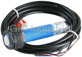
Honeywell FL7M-3J6HD Cylindrical Proximity Sensors
Part Number
FL7M-3J6HD
Price
Request Quote
Manufacturer
HONEYWELL SENSING & CONTROL
Lead Time
Request Quote
Category
None
Specifications
Control output
Switching current: 3 to 100mA, Voltage drop: 3V max., Output dielectric strength: 30Vdc
Dielectric strength
1,000Vac, 50/60Hz for 1 minute
Differential travel
15% max. of sensing distance
Insulation resistance
50M min. (by 500Vdc megger)
Leakage current
0.55mA max.
Operating temperature range
~25 to +70°C
Operating voltage range
10 to 30Vdc
Protection
IP67G
Rated supply voltage
12/24Vdc
Shock resistance
490m/s2 10 times in X, Y and Z directions
Storage temperature range
~40 to +85°C
Supply voltage characteristics
1% max. with 15% voltage fluctuation with rated supply voltage as standard voltage in sensing distance
Vibration resistance
10 to 55Hz, 1.5mm peak-to-peak amplitude, 2 hrs in X, Y and Z directions
Datasheet

Extracted Text
6 Specifications DC 2-wire Type FL7N/M Series (shielded/unshielded) Cylindrical Proximity Sensors FEATURES Rigid Structure, Highly Water-proof DC 2-wire Type with Improved Visibility Indi- cator Lamps. click DC 2-wire reducing wiring costs. Stable sensing area displayed by setting indicator. Rigid housing allows higher tightening torque. Indicator lamp can be confirmed from any direction. (firefly-glow indicator) Lowest current consumption: 0.55mA. (shielded type with a firefly-glow indi- cator) High seal capability: IP67G, core leads shielded. (shielded type with a firefly-glow indicator) Highest response: 2kHz. (M8 shielded type with a firefly-glow indicator) Non-polar DC 2-wire long sensing distance model available. ORDER GUIDE Shielded General type (threaded) Cord Appearance characteristics Operation Setting Sensing distance Catalog listing mode indication Dimensions Oil Sensor package style (O.D.) resistance Fire-fly indicator N.O. FL7M-2J6HD 2mm M8 Pre-leaded type N.C. FL7M-2K6H (cord length 2m) FL7M-3J6HD N.O. FL7M-3J6HDG M12 3mm FL7M-3K6H N.C. FL7M-3K6HG N.O. FL7M-7J6HD 7mm M18 N.C. FL7M-7K6H N.O. FL7M-10J6D M30 10mm N.C. FL7M-10K6 Fire-fly indicator N.O. FL7M-2J6HD-CN03 2mm M8 Pre-leaded connector type N.C. FL7M-2K6H-CN03 (cord length 30cm) N.O. FL7M-3J6HD-CN03 3mm M12 N.C. FL7M-3K6H-CN03 N.O. FL7M-7J6HD-CN03 M18 7mm N.C. FL7M-7K6H-CN03 N.O. FL7M-10J6D-CN03 10mm M30 N.C. FL7M-10K6-CN03 Window indicator N.O. FL7M-3J6HD-CN 3mm M12 Connector type N.C. FL7M-3K6H-CN N.O. FL7M-7J6HD-CN M18 7mm N.C. FL7M-7K6H-CN N.O. FL7M-10J6D-CN 10mm M30 N.C. FL7M-10K6-CN No. CP-PC-2216E 1 General type (non-threaded) Pre-leaded type Cord Appearance characteristics Operation Setting Sensing distance Catalog listing mode indication Dimensions Oil Sensor package style (O.D.) resistance Window indicator N.O. FL7N-2J6HD 2mm 6.5dia. N.C. FL7N-2K6H Spatter-guarded type (threaded, with a window indicator) Cord Appearance characteri- stics Operation Setting Spatter- Sensing distance Catalog listing mode indication guarded Dimensions Oil Sensor package style (O.D.) resistance Window indicator N.O. FL7M-3J6HW M12 3mm Pre-leaded type N.C. FL7M-3K6HWE N.O. FL7M-7J6HW 7mm M18 N.C. FL7M-7K6HWE N.O. FL7M-10J6W 10mm M30 N.C. FL7M-10K6WE Window indicator N.O. FL7M-3J6HW-CN03 M12 3mm Pre-leaded connector type N.C. FL7M-3K6HWE-CN03 N.O. FL7M-7J6HW-CN03 7mm M18 N.C. FL7M-7K6HWE-CN03 N.O. FL7M-10J6W-CN03 10mm M30 N.C. FL7M-10K6WE-CN03 Note: Black cap for FL7M-10K6WET-CN Long sensing distance non-polar type (thrended) Cord Appearance characteristics Operation Setting Sensing distance Catalog listing mode indication Dimensions Oil Sensor package style (O.D.) resistance Fire-fly indicator FL7M-4W6 N.O. Pre-leaded type M12 4mm FL7M-4Y6 (cordlength2m) N.O. FL7M-8W6 M18 8mm N.C. FL7M-8Y6 N.O. FL7M-15W6 15mm M30 N.C. FL7M-15Y6 Fire-fly indicator N.O. FL7M-4W6-CN03 M12 4mm Pre-leaded type N.C. FL7M-4Y6-CN03 (cordlength30cm) N.O. FL7M-8W6-CN03 M18 8mm N.C. FL7M-8Y6-CN03 N.O. FL7M-15JW6-CN03 15mm M30 N.C. FL7M-15Y6-CN03 2 Unshielded (threaded) Cord Appearance characteristics Operation Setting Sensing distance Catalog listing mode indication Dimensions Oil Sensor package style (O.D.) resistance Fire-fly indicator N.O. FL7M-4J6ND M8 4mm Pre-leaded type N.C. FL7M-4K6N (cord length 2m) N.O. FL7M-8J6ND 8mm M12 N.C. FL7M-8K6N N.O. FL7M-14J6ND 14mm M18 N.C. FL7M-14K6N N.O. FL7M-24J6ND M30 24mm N.C. FL7M-24K6N Fire-fly indicator N.O. FL7M-4J6ND-CN03 4mm M8 Pre-leaded connector type N.C. FL7M-4K6N-CN03 (cord length 30cm) N.O. FL7M-8J6ND-CN03 8mm M12 N.C. FL7M-8K6N-CN03 N.O. FL7M-14J6ND-CN03 M18 14mm N.C. FL7M-14K6N-CN03 N.O. FL7M-24J6ND-CN03 24mm M30 N.C. FL7M-24K6N-CN03 Window indicator N.O. FL7M-8J6ND-CN 8mm M12 Connector type N.C. FL7M-8K6N-CN N.O. FL7M-14J6ND-CN M18 14mm N.C. FL7M-14K6N-CN N.O. FL7M-24J6ND-CN 24mm M30 N.C. FL7M-24K6N-CN 3 SPECIFICATIONS Shielded General type Catalog listing FL7M-2 6H FL7M-3 6H FL7M-7 6H FL7M-10 6 Actuation method High-frequency oscillation type +2 Rated sensing distance 2 0.2mm 3 0.3mm 7 0.7mm 10 mm ~1 Usable sensing distance 0to1.4mm 0to2.1mm 0to4.9mm 0to7.0mm Standard target object 8 8mm, 1mm thick iron 12 12mm, 1mm thick iron 18 18mm, 1mm thick iron 30 30mm, 1mm thick iron Differential travel 15% max. of sensing distance Rated supply voltage 12/24Vdc Operating voltage range 10 to 30Vdc Leakage current 0.55mA max. Control output Switching current: 3 to 100mA, Voltage drop: 3V max., Output dielectric strength: 30Vdc Operating frequency 2kHz 1.5kHz 500Hz 10% max. for the range of ~25 to +70˚C when +25˚C is taken as standard temperature Temperature characteristics in sensing distance ( 15% max. for the -2 6H ) Supply voltage characteristics 1% max. with 15% voltage fluctuation with rated supply voltage as standard voltage in sensing distance N.O. type: Operation indication: Lights (red or green) at output Indicator lamps Setting indication: Lights (green) in stable sensing area N.C. type: Operation indication: Goes out (red) in sensing area Operating temperature range ~25 to +70˚C Storage temperature range ~40 to +85˚C Insulation resistance 50M min. (by 500Vdc megger) Dielectric strength 1,000Vac, 50/60Hz for 1 minute Vibration resistance 10 to 55Hz, 1.5mm peak-to-peak amplitude, 2 hrs in X, Y and Z directions 2 Shock resistance 490m/s 10 times in X, Y and Z directions Protection IP67G Approx. 50g Approx. 60g Approx. 130g Approx. 230g Weight Main unit with 2m Main unit with 2m Main unit with 2m Main unit with 2m pre-leaded cable pre-leaded cable pre-leaded cable pre-leaded cable Circuit protection Surge absorption, load short-circuit protection, reverse connection protection circuit Wiring method Pre-leaded connector, pre-leaded Sensor Case SUS Ni-plated brass Sensing face PBT Connector Housing -CN03: polyester elastomer Holder Glass-lined polyester resin Contact Gold-plated brass • Installation Instructions No.: CP-UM-5110E 4 Material Non-threaded type/spatter-guarded type Catalog listing FL7 -2 6H FL7M-3 6HW FL7M-7 6HW FL7M-10 6W Actuation method High-frequency oscillation type Rated sensing distance 2 0.2mm 3 0.3mm 7 0.7mm 10 1mm Usable sensing distance 0to1.4mm 0to2.1mm 0to4.9mm 0to7.0mm Standard target object 8 8mm, 1mm thick iron 12 12mm, 1mm thick iron 18 18mm, 1mm thick iron 30 30mm, 1mm thick iron Differential travel 15% max. of sensing distance Rated supply voltage 12/24Vdc Operating voltage range 10 to 30Vdc Leakage current 0.55mA max. Switching current: 3 to 100mA Control output Voltage drop: 3.0V max. Output dielectric strength: 30Vdc Operating frequency 1kHz 1,500Hz 500Hz 500Hz 10% max. for the range of ~25 to +70˚C when +25˚C is taken as standard temperature Temperature characteristics in sensing distance ( 15% max. for the -2 6H ) Supply voltage characteristics 1% max. with 15% voltage fluctuation with rated supply voltage as standard voltage in sensing distance N.O. type: Operation indication: Lights (orange or green) at output Indicator lamps Setting indication: Lights (green) in stable sensing area N.C. type: Operation indication: Goes out (orange) in sensing area Operating temperature range ~25 to +70˚C Storage temperature range ~40 to +85˚C Insulation resistance 50M min. (by 500Vdc megger) Dielectric strength 1,000Vac, 50/60Hz for 1 minute Vibration resistance 10 to 55Hz, 1.5mm peak-to-peak amplitude, 2 hrs in X, Y and Z directions 2 Shock resistance 980m/s 10 times in X, Y and Z directions Protection IP67 (IEC standard), IP67G (JAM standard) Approx. 50g Approx. 60g Approx. 130g Approx. 230g Weight Main unit with 2m Main unit with 2m Main unit with 2m Main unit with 2m pre-leaded cable pre-leaded cable pre-leaded cable pre-leaded cable Circuit protection Surge absorption, load short-circuit protection, reverse connection protection circuit Wiring method Connector, pre-leaded connector, pre-leaded Sensor Case SUS Ni-plated brass, W type: Ni-plated brass, fluorine resin coated Sensing face PBT, W type: fluorine resin Connector Housing -CN03: polyester elastomer Holder Glass-lined polyester resin Contact Gold-plated brass 5 Material Long sensing distance non-polar type Catalog listing FL7M-4 6 FL7M-8 6 FL7M-15 6 Actuation method High-frequency oscillation type (shielded) Rated sensing distance 4 0.4mm 8 0.8mm 15 1.5mm Usable sensing distance 0to3.2mm 0to6.4mm 0to12mm Standard target object 12 12mm, 1mm thick iron 18 18mm, 1mm thick iron 30 30mm, 1mm thick iron Differential travel 15% max. of sensing distance Rated supply voltage 12/24Vdc Operating voltage range 10 to 30Vdc Leakage current 0.55mA max. Output operational mode DC 2-wire type, tramsistor output Switching current: 3 to 100mA, Voltage drop: 5.0V max. (swoting current: 100mA, cord length: 2mm) Control output Output dielectric strength: 30Vdc Operating frequency 1,000Hz 500Hz 300Hz 10% max. for the range of ~25 to +70˚C when +25˚C is taken as standard temperature Temperature characteristics in sensing distance Supply voltage characteristics 1% max. with 15% voltage fluctuation with rated supply voltage as standard voltage in sensing distance N.O. type: Operation indication: Lights (orange or green) at output Indicator lamps Setting indication: Lights (green) in stable sensing area N.C. type: Operation indication: Goes out (orange) in sensing area Operating temperature range ~25 to +70˚C Storage temperature range ~40 to +85˚C Insulation resistance 50M min. (by 500Vdc megger) Dielectric strength 1,000Vac, 50/60Hz for 1 minute Vibration resistance 10 to 55Hz, 1.5mm peak-to-peak amplitude, 2 hrs in X, Y and Z directions 2 Shock resistance 980m/s 10 times in X, Y and Z directions Protection IP67 (IEC standard), IP67G (JAM standard) Weight Approx. 60g Approx. 130g Approx. 230g Circuit protection Surge absorption, load short-circuit protection, reverse connection protection circuit Wiring method Pre-leaded connector, pre-leaded Sensor Case Ni-plated brass Sensing face PBT Bush Nylon Cord protector Elastomer Connector Housing Polyester elastomer Holder Glass-lined polyester resin Contact Gold-plated brass • Installation Instructions No.: CP-UM-5291E 6 Material Unshielded Catalog listing FL7M-4 6N FL7M-8 6N FL7M-14 6N FL7M-24 6N Actuation method High-frequency oscillation type (unshielded) Rated sensing distance 4 0.4mm 8 0.8mm 14 1.4mm 24 2.4mm Usable sensing distance 0to2.8mm 0to5.6mm 0to9.8mm 0to16.8mm Standard target object 20 20mm, 1mm thick iron 30 30mm, 1mm thick iron 30 30mm, 1mm thick iron 54 54mm, 1mm thick iron Differential travel 15% max. of sensing distance Rated supply voltage 12/24Vdc Operating voltage range 10 to 30Vdc Leakage current 1.0mA max. Control output Switching current: 4 to 100mA, Voltage drop: 3.3V max., Output dielectric strength: 30Vdc Operating frequency 800Hz 600Hz 400Hz 100Hz Temperature characteristics 10% max. for the range of ~25 to +70˚C when +25˚C is taken as standard temperature in sensing distance Supply voltage characteristics 1% max. with 15% voltage fluctuation with rated supply voltage as standard voltage in sensing distance N.O. type: Operation indication: Lights (red or green) at output Indicator lamps Setting indication: Lights (green) in stable sensing area N.C. type:Operation indication:Goesout (red)in sensing area Operating temperature range ~25 to +70˚C Storage temperature range ~40 to +85˚C Insulation resistance 50M min. (by 500Vdc megger) Dielectric strength 1,000Vac, 50/60Hz for 1 minute Vibration resistance 10 to 55Hz, 1.5mm peak-to-peak amplitude, 2 hrs in X, Y and Z directions 2 Shock resistance 490m/s 10 times in X, Y and Z directions Protection IP67 (IEC standard) Approx. 50g Approx. 60g Approx. 80g Approx. 190g Weight Main unit with 2m Main unit with 2m Main unit with 2m Main unit with 2m pre-leaded cable pre-leaded cable pre-leaded cable pre-leaded cable Circuit protection Surge absorption, load short-circuit protection, reverse connection protection circuit Wiring method Connector, pre-leaded connector, pre-leaded Sensor Case SUS Ni-plated brass Sensing face PBT Connector Housing -CN: Ni-plated brass, -CN03: polyester elastomer Holder Glass-lined polyester resin Contact Gold-plated brass • Installation Instructions No.: CP-UM-3108E ABOUT SETTING INDICATION The proximity sensor can detect objects reliably by bringing the proximity sensor close to the target object and setting the sensor at the position (N.O. indication) where the indicator lamp changes from red to green. Note: When the target object is made of a different material such as aluminum, copper and stainless steel to the standard target object (iron), the setup point where the indicator lamp changes color is shorter than 80% maximum. 7 Material WIRING DIAGRAM General/spatter-guarded/unshielded types Long sensing distance non-polar type Note: The load can be connected to either of the power supplies. Note: The load can be connected to either of the power supplies. SENSING AREA DIAGRAMS (typical examples) Shielded Unshielded SENSING DISTANCE ACCORDING TO MATERIAL & SIZE OF OBJECT (typical examples) Shielded FL7 -2 6H FL7M-3 6H 8 FL7M-7 6H FL7M-10 6 Unshielded FL7M-4 6N FL7M-8 6N FL7M-14 6N FL7M-24 6N 9 VOLTAGE DROP CHARACTERISTICS (typical examples) (With a firefly-glow indicator) shielded (With a window indication) shielded/unshielded (in10to30Vdc) (at 24Vdc) LEAKAGE CURRENT CHARACTERISTICS (typical examples) (With a firefly-glow indicator) shielded and spatter-guarded (With a window indicator) shielded types Unshielded 10 EXTERNAL DIMENSIONS Long sensing distance non-polar type sensor has the projection of resin as shown below. Catalog listing ‘‘A’’ distance (mm) FL7M-4 6 0.6 FL7M-8 6 0.6 FL7M-15 6 1.0 (unit: mm) Shielded General type/long sensing distance non-polar type (threaded) Pre-leaded type FL7M-2 6H FL7M-4 6, FL7M-3 6H 2 Vinyl-insulated cord (oil-resistant: 0.3mm , 27/0.12, 2-core) 4.1mm The FL7M-4 6 has a 0.6mm projection of resin at the sensing face. dia. (The total length is same.) Refer to the previous item. Cap color: blue Numbers in parentheses indicate dimensions for G type.Vinyl-insulat- 2 ed cord (oil-resistant: 0.3mm , 27/0.12, 2-core) 4.1mm dia. Cap color: blue FL7M-8 6, FL7M-7 6H FL7M-15 6, FL7M-10 6 The FL7M-8 6 has a 0.6mm projection of resin at the sensing face. The FL7M-15 6 has a 1.0mm projection of resin at the sensing face. (The total length is same.) Refer to the previous item. 2 (The total length is same.) Refer to the previous item. Vinyl-insulated cord (oil-resistant: 0.5mm , 20/0.18, 2-core) 5.7dia. 2 Vinyl-insulated cord (oil-resistant: 0.5mm , 20/0.18, 2-core) 5.7dia. Cap color: blue Cap color: blue 11 Pre-leaded connector type (unit: mm) FL7M-2 6H -CN03 FL7M-4 6-CN03, FL7M-3 6H -CN03 2 Vinyl-insulated cord (Vibration-resistant, oil-resistant: 0.3mm , 27/0.12, The FL7M-4 6-CN03 has a 0.6mm projection of resin at the sensing 2-core) 4.1dia. face. (The total length is same.) Refer to the previous item. 2 Cap color: blue Vinyl-insulated cord (Vibration-resistant, oil-resistant: 0.3mm , 27/0.12, 2-core) 4.1dia. Cap color: blue FL7M-8 6 -CN03, FL7M-7 6H -CN03 FL7M-15 6 -CN03, FL7M-10 6 -CN03 The FL7M-8 6 -CN03 has a 0.6mm projection of resin at the The FL7M-15 6 -CN03 has a 1.0mm projection of resin at the sensing face. (The total length is same.) Refer to the previous item. 2 sensing face. (The total length is same.) Refer to the previous item. Vinyl-insulated cord (Vibration-resistant, oil-resistant: 0.5mm , 20/0.18, 2 Vinyl-insulated cord (Vibration-resistant, oil-resistant: 0.5mm , 20/0.18, 2-core) 5.7dia. 2-core) 5.7dia. Cap color: blue Cap color: blue Connectot type (general type only) FL7M-3 6H -CN FL7M-7 6H -CN Cap color: blue Cap color: blue 12 FL7M-10 6 -CN (unit: mm) Cap color: blue General type (Non-threaded) FL7M-2 6H 2 Vinyl-insulated cord (oil-resistant: 0.3mm , 27/0.12, 2-core) 4.2mm dia. Cap color: blue Spatter-guarded Pre-leaded type FL7M-3 6HW -R FL7M-7 6HW -R Vinyl-insulated cord (flame-resistant, oil-resistant, bend-resistant: 0.5 Vinyl-insulated cord (flame-resistant, oil-resistant, bend-resistant: 0.5 2 2 mm , 21/0.18, 2-core) 5.7dia. mm , 21/0.18, 2-core) 5.7dia. Cap color: white Cap color: white 13 FL7M-10 6W -R (unit: mm) Vinyl-insulated cord (flame-resistant, oil-resistant, bend-resistant: 0.5 2 mm , 21/0.18, 2-core) 5.7dia. Cap color: white Pre-leaded connector type FL7M-3 6HW -CN03 FL7M-7 6HW -CN03 Vinyl-insulated cord (flame-resistant, oil-resistant, bend-resistant: 0.5 Vinyl-insulated cord (flame-resistant, oil-resistant, bend-resistant: 0.5 2 2 mm , 21/0.18, 2-core) 5.7dia. mm , 21/0.18, 2-core) 5.7dia. Cap color: white Cap color: white FL7M-10 6W -CN03 Vinyl-insulated cord (flame-resistant, oil-resistant, bend-resistant: 0.5 2 mm , 21/0.18, 2-core) 5.7dia. Cap color: white 14 (unit: mm) Unshielded (threaded) Pre-leaded type FL7M-4 6N FL7M-8 6N 2 2 Vinyl-insulated cord (oil-resistant: 0.3mm , 27/0.12, 2-core) 4.2mm Vinyl-insulated cord (oil-resistant: 0.3mm , 27/0.12, 2-core) 4.2mm dia. dia. Cap color: blue Cap color: blue FL7M-14 6N FL7M-24 6N 2 2 Vinyl-insulated cord (oil-resistant: 0.3mm , 27/0.12, 2-core) 4.2mm Vinyl-insulated cord (oil-resistant: 0.3mm , 27/0.12, 2-core) 4.2mm dia. dia. Cap color: blue Cap color: blue Pre-leaded connector type FL7M-4 6N -CN FL7M-8 6N -CN Cap color: blue Cap color: blue 15 FL7M-14 6N -CN FL7M-24 6N -CN (unit: mm) Cap color: blue Cap color: blue Connector type FL7M-8 6N -CN FL7M-14 6N -CN Cap color: blue Cap color: blue FL7M-24 6N -CN Cap color: blue MOUNTING BRACKET (sold separately) Mounting brackets are made of polyacetal resin. Screw Dimensions (mm) Two screws and two washers are provided for each bracket. Catalog dimensions listing AB C D E F G Diameter Neck FL-PA112 25 12 20 12 36 6 9.5 M4 25 FL-PA118 30/32 15 30 18 45 7.5 14.5 M5 35 FL-PA130 40/45 15 50 30 60 10 24.5 M5 55 Allowable tightening strength of bracket Allowable tightening strength Catalog listing Remarks (N-m) FL-PA112 0.98 M4 screw used FL-PA118 and FL-PA130 screw holes are oblong. FL-PA118 1.5 M5 screw used FL-PA130 1.5 M5 screw used 16 PROTECTIVE COVER (sold separately) Protective covers (material: poly- Dimensions (mm) acetal resin) are available for Catalog listing AB C D shielded models. Select a model +0.2 according to the sensor’sexter- FL-PA12 14dia. 5 0.5 M12 1 ~0.1 nal dimensions. 0.2 FL-PA18 21dia. 6 0.5 M18 1 0.2 FL-PA30 33dia. 8 1.5 M30 1.5 WIRING General type/spatter-guarded type/unshielded type Long sensing distance non-polar type Pre-leaded type Pre-leaded type Pre-leaded connector type (N.O. type) Pre-leaded connector type (N.O. type) Preleaded connector type (N.C. type) Preleaded connector type (N.C. type) - The load be connected at both poles. - The load be connected at both poles. - The load must be used when power is - LED operates normally during a load applied to sensors. short circuit, therefore check the wiring Combination of short circuit and wrong when output is wrong. wiring will cause permanent damage, - When connecting a connector, fasten regardless of short circuit protection. tightly by hand. - LED operates normally during a load short circuit, therefore check the wiring when output is wrong. Connector pin Connector pin assignment assignment - When connecting a connector, fasten tightly by hand. 17 Note 1 CONNECTOR SPECIFICATIONS Item Specifications Operating voltage/current 5Vac/dc 5mA min., 125Vac/dc, 3A max. Insulation resistance 100M min. (by 500Vdc megger) Dielectric strength 1,500Vdc for 1 minute (across contacts, and contacts and connector housing) 40m max. Initial contact resistance (excluding code conductor-intrinsic when energized by 3A on a male-female contact combination) Connector withstand stress 0.4 to 4.0N (per contact) Number of connector insertions 50 times Connector tightening strength 0.8N-m min. (Note 2) Cord pullout strength 100N min. Vibration resistance 10 to 55Hz, 1.5mm peak-to-peak amplitude, 2 hrs in X, Y and Z directions 2 Shock resistance 300m/s ,3 timesinX,YandZdirections Protection IP67 Operating temperature range ~10 to +70˚C Storage temperature range ~20 to +80˚C Operating humidity range 95%RH max. Contact: gold-plated brass Contact holder: glass-lined polyester resin Material Housing: polyester elastomer Coupling: Ni-plated brass O-ring: NBR Note 1: Specifications assume Yamatake male/female connectors. Note 2: The recommended torque is 0.4 to 0.6N-m. If fastened poorly, the IP67 protection is lost, or looseness occurs. Fasten the connector securely by hand. CONNECTION CORD WITH CONNECTOR Be sure to use PA5 Series cord with VA connector when connecting a pre-leaded connector or connector sensors. PA5 Series cord with VA connector Shape Power supply Cord length Catalog listing Lead color 2m PA5-4ISX2HK 5m PA5-4ISX5HK dc 1-brown, 2-white, 3-blue, 4-black 2m PA5-4ILX2HK 5m PA5-4ILX5HK PA5 Series cord Fastening the connector with VA connector Align the grooves of the connectors and turn the fastening screw of the VA connector of the PA5 cord by hand until it fits tightly Pre-leaded connector model with the screw on the sensor side. Female Male Connector model Female 18 PRECAUTIONS Unshielded Mounting The allowable tightening torque varies according to the distance from the tip of the sensing head. Shaded areas indicate surrounding metal Shielded other than the target object. FL7N FL7M A: Dimension to tip (sensing face) of prox- imitysensorfrommountingsurface B: Dimension to front iron plate from tip (sensing face) of proximity sensor C: Dimensiontofrontironplateofproximity switch when A=0 Unshielded Catalog listing A (mm) B (mm) C (mm) FL7 -2 6H 088 FL7M-3 6H 089 FL7M-4 6 2.5 12 9 FL7M-7 6H 02013.5 FL7M-8 6 3.5 24 13.5 Allowable tightening torque (N-m) A dimensions FL7M-10 6 04022.5 Catalog listing (mm) AB FL7M-15 6 64522.5 FL7M-2 6 10 9 12 FL7M-4 6N 13 8 12 FL7M-3 6 10 20 30 FL7M-8 6N 15 20 20 FL7M-4 6 10 20 30 FL7M-14 6N 22 40 35 FL7M-7 6 0~ 70 FL7M-24 6N 32 90 60 FL7M-8 6 0~ 70 FL7M-10 6 0~ 150 Mutual interference prevention FL7M-15 6 0~ 150 When mounting proximity sensors in parallel or facing each FL7N-2 6H 8 Cannot be tightened 0.3 other, mutual interference may cause the sensor to malfunction. Maintain at least the spaces indicated in the figures below. FL7M-2 6H 10 5.9 11.8 FL7M-3 6H 12 11.8 19.6 FL7M-3 6H 12 11.8 19.6 FL7M-7 6H 15 29.4 49 FL7M-10 6 17 49 147 FL7M-4 6N 0~ 7.8 FL7M-8 6N 0~ 19.6 FL7M-14 6N 10 29.4 49 FL7M-24 6N 12 49 147 Catalog listing A (mm) B (mm) Note: The table shows the allowable strength when toothed washers FL7 -2 6H 16 20 (provided) are used. FL7M-3 6H 20 30 Influence of surrounding metal FL7M-4 6 25 25 Metal other than the target object surrounding the sensor may FL7M-7 6H 35 50 influence operating characteristics. Maintain the following space FL7M-8 6 40 50 between the sensor and surrounding metal: FL7M-10 6 70 100 Shielded FL7M-15 6 90 110 FL7M-4 6N 60 80 FL7M-8 6N 100 120 FL7M-14 6N 110( 60) 200(100) FL7M-24 6N 300(100) 350(130) Numbers in parentheses ‘‘()’’ indicate the distance when different- frequency types are combined. 19 Shielded Unshielded Shielded (with a firefly- glow indicator) Unshielded Shielded Unshielded Shielded Cautions during series or parallel connection Relay loads (1) Series connection (AND connection) The voltage drop of the FL7M Series is 3.3V (shielded T type: • When connecting two or more proximity sensors in series, er- 3.5V). roneous output (1 to 3ms) may occur without the rated current Pay attention to this voltage drop when using a relay load. (With being supplied to each of the sensors. For this reason, series 12Vdc relays, switching is not possible.) connection of proximity sensors is not recommended. However, if proximity sensors must be connected in series, a Operation at power ON resistor of 10k must be provided in parallel to each of the After the power is turned ON, it takes 40ms or less until the sensors. However, note that the maximum leakage current in proximity sensor is ready for sensing. a series connection will be 3.5mA. When the load and the proximity sensor use different power Operation lag also will occur, resulting in increased voltage supplies, be sure to turn the proximity sensor ON before turning drop, and the operation indicator lamp will not light. the load ON. Operation lag = 40ms (number of series connections ~ 1) Voltage drop = voltage drop of single sensor number of Influence of leakage current series connected sensors Minimal current flows as leakage current for operating the cir- cuits even when the proximity sensor is OFF. Take sufficient care when restoring connected loads. Minimum cord bending radius (R) The minimum bending radius (R) of the cord is 3 times cord di- ameter, take care not to excessively bend the cord beyond this (2) Parallel connection (OR connection) radius. Also, do not excessively bend the cord within 30mm of • When connecting two or more proximity sensors in parallel, the cord lead-in port. leakage current increases as follows, and may result in faulty load restore. (Leakage current = Leakage current of single sensor number of series connected sensors) • When two or more sensors turn ON in a parallel connection, one (or some) of the sensors may not indicate operation. This is not an abnormality. RESTRICIONS ON USE This product has been designed, developed and manufactured for general-purpose application in machinery and equipment. Accordingly, when used in applications outlined below, special care should be taken to implement a fail-safe and/or redundant design concept as well as a periodic maintenance program. - Safety devices for plant worker protection - Start/stop control devices for transportation and material handling machines - Aeronautical/aerospace machines - Control devices for nuclear reactors Never use this product in applications where human safety may be put at risk. (01) Printed in Japan (SP) 1st Edition: lssued in Apr., 2002 20 2nd Edition: Issued in Oct., 2003
Frequently asked questions
How does Industrial Trading differ from its competitors?

Is there a warranty for the FL7M-3J6HD?
Which carrier will Industrial Trading use to ship my parts?
Can I buy parts from Industrial Trading if I am outside the USA?
Which payment methods does Industrial Trading accept?
Why buy from GID?

Quality
We are industry veterans who take pride in our work

Protection
Avoid the dangers of risky trading in the gray market

Access
Our network of suppliers is ready and at your disposal

Savings
Maintain legacy systems to prevent costly downtime

Speed
Time is of the essence, and we are respectful of yours
Related Products
Honeywell 24CX2 Enclosed basic switch
Honeywell Microswitch Ultrasonic Sensor. 32-122F 1-6VDC 16HZ 18MM
AML BUTTON/LENS SQUARE PB RED
Honeywell EX-AR Switch Limit Explosion Proof 15 amps spdt roller lever
Honeywell EX-AR20 Switch 15AMP 125/250/480VAC Explosion Proof spdt
Honeywell FL7M-10J6D Cylindrical Proximity Sensors
Request a Quote

The quote request has been received
Close

Facing challenges or have inquiries? Feel free to contact us!
Call Us +1-469-283-2440
What they say about us
FANTASTIC RESOURCE
One of our top priorities is maintaining our business with precision, and we are constantly looking for affiliates that can help us achieve our goal. With the aid of GID Industrial, our obsolete product management has never been more efficient. They have been a great resource to our company, and have quickly become a go-to supplier on our list!
Bucher Emhart Glass
EXCELLENT SERVICE
With our strict fundamentals and high expectations, we were surprised when we came across GID Industrial and their competitive pricing. When we approached them with our issue, they were incredibly confident in being able to provide us with a seamless solution at the best price for us. GID Industrial quickly understood our needs and provided us with excellent service, as well as fully tested product to ensure what we received would be the right fit for our company.
Fuji
HARD TO FIND A BETTER PROVIDER
Our company provides services to aid in the manufacture of technological products, such as semiconductors and flat panel displays, and often searching for distributors of obsolete product we require can waste time and money. Finding GID Industrial proved to be a great asset to our company, with cost effective solutions and superior knowledge on all of their materials, it’d be hard to find a better provider of obsolete or hard to find products.
Applied Materials
CONSISTENTLY DELIVERS QUALITY SOLUTIONS
Over the years, the equipment used in our company becomes discontinued, but they’re still of great use to us and our customers. Once these products are no longer available through the manufacturer, finding a reliable, quick supplier is a necessity, and luckily for us, GID Industrial has provided the most trustworthy, quality solutions to our obsolete component needs.
Nidec Vamco
TERRIFIC RESOURCE
This company has been a terrific help to us (I work for Trican Well Service) in sourcing the Micron Ram Memory we needed for our Siemens computers. Great service! And great pricing! I know when the product is shipping and when it will arrive, all the way through the ordering process.
Trican Well Service
GO TO SOURCE
When I can't find an obsolete part, I first call GID and they'll come up with my parts every time. Great customer service and follow up as well. Scott emails me from time to time to touch base and see if we're having trouble finding something.....which is often with our 25 yr old equipment.
ConAgra Foods